WO2009154103A1 - 接続装置および光イメージング装置 - Google Patents
接続装置および光イメージング装置 Download PDFInfo
- Publication number
- WO2009154103A1 WO2009154103A1 PCT/JP2009/060518 JP2009060518W WO2009154103A1 WO 2009154103 A1 WO2009154103 A1 WO 2009154103A1 JP 2009060518 W JP2009060518 W JP 2009060518W WO 2009154103 A1 WO2009154103 A1 WO 2009154103A1
- Authority
- WO
- WIPO (PCT)
- Prior art keywords
- connector
- fixing member
- connection
- optical fiber
- adapter
- Prior art date
Links
Images


Classifications
-
- G—PHYSICS
- G02—OPTICS
- G02B—OPTICAL ELEMENTS, SYSTEMS OR APPARATUS
- G02B6/00—Light guides; Structural details of arrangements comprising light guides and other optical elements, e.g. couplings
- G02B6/24—Coupling light guides
- G02B6/36—Mechanical coupling means
- G02B6/38—Mechanical coupling means having fibre to fibre mating means
- G02B6/3807—Dismountable connectors, i.e. comprising plugs
- G02B6/381—Dismountable connectors, i.e. comprising plugs of the ferrule type, e.g. fibre ends embedded in ferrules, connecting a pair of fibres
- G02B6/3825—Dismountable connectors, i.e. comprising plugs of the ferrule type, e.g. fibre ends embedded in ferrules, connecting a pair of fibres with an intermediate part, e.g. adapter, receptacle, linking two plugs
-
- G—PHYSICS
- G02—OPTICS
- G02B—OPTICAL ELEMENTS, SYSTEMS OR APPARATUS
- G02B6/00—Light guides; Structural details of arrangements comprising light guides and other optical elements, e.g. couplings
- G02B6/24—Coupling light guides
- G02B6/36—Mechanical coupling means
- G02B6/38—Mechanical coupling means having fibre to fibre mating means
- G02B6/3807—Dismountable connectors, i.e. comprising plugs
- G02B6/3833—Details of mounting fibres in ferrules; Assembly methods; Manufacture
- G02B6/3851—Ferrules having keying or coding means
-
- G—PHYSICS
- G02—OPTICS
- G02B—OPTICAL ELEMENTS, SYSTEMS OR APPARATUS
- G02B6/00—Light guides; Structural details of arrangements comprising light guides and other optical elements, e.g. couplings
- G02B6/24—Coupling light guides
- G02B6/36—Mechanical coupling means
- G02B6/38—Mechanical coupling means having fibre to fibre mating means
- G02B6/3807—Dismountable connectors, i.e. comprising plugs
- G02B6/389—Dismountable connectors, i.e. comprising plugs characterised by the method of fastening connecting plugs and sockets, e.g. screw- or nut-lock, snap-in, bayonet type
- G02B6/3891—Bayonet type
-
- G—PHYSICS
- G02—OPTICS
- G02B—OPTICAL ELEMENTS, SYSTEMS OR APPARATUS
- G02B6/00—Light guides; Structural details of arrangements comprising light guides and other optical elements, e.g. couplings
- G02B6/24—Coupling light guides
- G02B6/36—Mechanical coupling means
- G02B6/38—Mechanical coupling means having fibre to fibre mating means
- G02B6/3807—Dismountable connectors, i.e. comprising plugs
- G02B6/3833—Details of mounting fibres in ferrules; Assembly methods; Manufacture
- G02B6/3847—Details of mounting fibres in ferrules; Assembly methods; Manufacture with means preventing fibre end damage, e.g. recessed fibre surfaces
-
- G—PHYSICS
- G02—OPTICS
- G02B—OPTICAL ELEMENTS, SYSTEMS OR APPARATUS
- G02B6/00—Light guides; Structural details of arrangements comprising light guides and other optical elements, e.g. couplings
- G02B6/24—Coupling light guides
- G02B6/36—Mechanical coupling means
- G02B6/38—Mechanical coupling means having fibre to fibre mating means
- G02B6/3807—Dismountable connectors, i.e. comprising plugs
- G02B6/3897—Connectors fixed to housings, casing, frames or circuit boards
Definitions
- the present invention relates to a connection device for connecting an optical fiber cable and its constituent members.
- optical fiber connectors As connection devices for connecting optical fiber cables is increasing mainly in the communication field.
- Specific examples of optical fiber connectors include FC connectors, SC connectors, MU connectors, and the like.
- These connectors are provided with a mechanism for avoiding relative rotation between the optical fiber cables in order to prevent the ends (contact surfaces) of the connected optical fiber cables from being damaged.
- a mechanism for avoiding relative rotation between the optical fiber cables in order to prevent the ends (contact surfaces) of the connected optical fiber cables from being damaged.
- circumferential rotation is avoided by pins and grooves
- SC connector and MU connector circumferential rotation is avoided by using each shape of the connector (for example, the following patents) References 1 and 2).
- connection device that rotates the optical fiber as in Patent Document 4 has an outer housing that does not rotate when the optical fiber cable is connected, and the internal rotating optical fiber is connected. There is a risk of damage due to a pushing load generated on the bearing constituted by the O-ring, and there is a possibility of breakage. As in Patent Document 3, a play for rotation is provided between the outer housing and the inner rotor. In this case, even if the housing is connected, the internal connector may not be completely connected, which is not preferable. Further, when the bearing is a disc-shaped flange, there is a possibility that inconvenience such as deformation due to friction may occur due to the rotating flange coming into contact with the non-rotating portion.
- An object of the present invention is made in view of such problems, and in a connection device for connecting an optical fiber cable, the contact of an internal member at the time of connector connection is reduced and the connection can be easily performed. .
- a connection device for connecting an optical fiber cable in which a first connection terminal is arranged inside the adapter device, and has a hollow portion with an open end, and a second connection terminal inside the connector device.
- a second fixing member having an outer wall formed so as to slide along the inner wall of the first fixing member when inserted into the first fixing member
- the housing of the adapter device Comprises at least one curved groove, at least one projection on a part of the outer wall of the housing of the connector device, further comprising an elastic member on the base end side of the second fixing member, and the groove
- the second fixing member further includes a disc-shaped flange, and the elastic member presses the disc-shaped flange when the convex portion is inserted along the groove portion, and the first connection terminal and the The connection device according to (1), wherein the connection device is configured to be coupled to the second connection terminal.
- the disk-like flange is the elastic member. It is comprised so that it may become non-contact with, The connection apparatus as described in said (1) characterized by the above-mentioned.
- connection according to (1) wherein the groove is configured to advance in a rotation direction perpendicular to the insertion direction after the convex portion makes a U-turn from the insertion direction. apparatus.
- connection device wherein the elastic member is a resin or a metal member.
- An optical imaging device including the connection device according to (1), wherein an optical fiber is provided.
- An optical probe that is rotatably incorporated, a control device that has a light source and transmits and receives signals to and from the probe,
- An optical imaging apparatus comprising the connection device for connecting the optical probe and the control device.
- the member in the connection device for connecting the optical fiber cable, the member is not damaged when the connector is connected, and the connection is ensured, and the contact of the internal member can be reduced during the internal driving after the connection. .
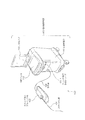
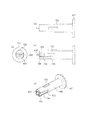
- FIG. 1 is a diagram illustrating an overall configuration of a catheter unit 101.
- FIG. FIG. 3 is a diagram illustrating a configuration of a distal end portion of a catheter unit 101. It is sectional drawing which shows the internal structure of a drive shaft connector. It is a partial cross section figure which shows the structure of an optical fiber. It is a figure which shows the internal structure (side connected with the base end of the drive shaft connector 202b) of the attaching part in the scanner / pullback part. It is a figure which shows the external appearance structure of a connector apparatus. It is a figure which shows the external appearance structure of an adapter apparatus.
- FIG. 110 It is a figure which shows operation
- FIG. 110 It is a figure which shows the adapter apparatus housing. It is an external view of a connector device and an adapter device (head 1102). It is sectional drawing of a connector apparatus and an adapter apparatus (head 1102). It is a perspective view of a connector apparatus and an adapter apparatus (head 1102). It is a figure which shows the state of the elastic member before connection of an optical fiber, and a housing fitting part. It is a figure which shows the state of the elastic member at the time of the connection of an optical fiber, and a housing fitting part. It is a figure which shows the state of the elastic member after the connection of an optical fiber, and a housing fitting part. It is a figure which shows the connector apparatus in 2nd Embodiment of the connection apparatus of this invention.
- connection device which is a kind of optical imaging apparatus
- OCT optical coherence tomographic diagnosis apparatus
- other medical devices may be used, and devices other than medical devices may be used.
- FIG. 1 is a diagram showing an external configuration of an optical coherence tomography diagnosis apparatus 100 to which a connection device according to the first embodiment of the present invention is applied.
- the optical coherence tomography diagnosis apparatus 100 includes a catheter unit 101 that is a detachable optical probe, a scanner / pullback unit 102, and an operation control device 103, and controls the scanner / pullback unit 102 and operation.
- the device 103 is connected by a signal line 104.
- the catheter unit 101 is directly inserted into a blood vessel and measures the state inside the blood vessel using low coherence light emitted from an imaging core (see FIGS. 2 and 3).
- the scanner / pullback unit 102 performs radial scanning of the optical imaging core in the catheter unit 101.
- the operation control device 103 has a function for inputting various set values and a function for processing data obtained by measurement and displaying it as a cross-sectional image when performing optical coherence tomography diagnosis.
- reference numeral 111 denotes a main body control unit which processes data obtained by measurement and outputs a processing result.
- Reference numeral 111-1 denotes a printer and a DVD recorder, which print the processing results in the main body control unit 111 or store them as data.
- Reference numeral 113 denotes an LCD monitor that displays a processing result in the main body control unit 111.
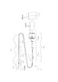
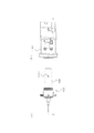
- the catheter unit 101 includes a long catheter sheath 201 that is inserted into a blood vessel and a connector unit 202 that is not inserted into the blood vessel and is disposed on the user's hand side for operation by the user. Composed.
- a tube 203 constituting a guide wire lumen is provided at the distal end of the catheter sheath 201.
- the catheter sheath 201 is formed as a continuous lumen from a connection portion with the tube 203 to a connection portion with the connector portion 202. (See FIG. 3 for details).
- an imaging core including an optical transmission / reception unit 221 that transmits and receives measurement light, and a coiled drive shaft 222 that includes an optical fiber cable and transmits a driving force for rotating the optical fiber cable. 220 is inserted through substantially the entire length of the catheter sheath 201.
- the connector section 202 includes a sheath connector 202a configured integrally with the proximal end of the catheter sheath 201 and a drive shaft connector 202b configured to rotatably fix the drive shaft 222 to the proximal end of the drive shaft 222.
- a kink protector 211 is provided at the boundary between the sheath connector 202a and the catheter sheath 201, whereby a predetermined rigidity is maintained, and bending (kink) due to a sudden change in physical properties can be prevented.
- the base end (see FIG. 4 for details) of the drive shaft connector 202b is configured to be connectable to a mounting portion of a scanner / pullback portion 102 (see FIG. 6 for details) described later (the connection device according to this embodiment is a , Applied in the connection of the optical fiber cable between the proximal end of the drive shaft connector 202b and the scanner / pullback portion 102).
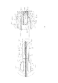
- an optical transmission / reception unit 221 includes a prism or mirror 221b and a housing 221a that holds the prism or mirror 221b. Measurement light is irradiated from the prism or mirror 221b toward the tissue in the body cavity, and the prism or mirror 221b is irradiated. The reflected light from the body cavity tissue is received.
- the drive shaft 222 is formed in a coil shape, and an optical fiber cable is disposed in the drive shaft 222 and extends from the optical transmission / reception unit 221 to the connector unit 202.
- the housing 221 a has an optical transmission / reception unit 221 b inside, and the base end side is connected to the drive shaft 222.
- a short coil-shaped elastic member 304 is provided on the tip side.
- the elastic member 304 is a stainless steel wire formed in a coil shape, and the elastic member 304 is arranged on the tip side, so that the stability during rotation of the imaging core 220 is improved.
- 303 is an X-ray contrast coil, which is provided for the purpose of confirming the position of the distal end portion of the catheter sheath 201 in the body under X-ray fluoroscopy.
- the tube 203 defines a hole into which the guide wire 305 can be inserted.
- the guide wire 305 is inserted into the body cavity in advance and used to guide the catheter sheath 201 to the affected area.
- the drive shaft 222 is capable of rotating and sliding with respect to the catheter sheath 201 and is flexible and has a characteristic capable of well transmitting the rotation, for example, by a multi-layered close contact coil made of a metal wire such as stainless steel. It is configured.
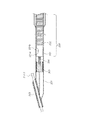
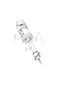
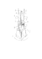
- FIG. 4 is a cross-sectional view showing the internal configuration of the base end of the drive shaft connector 202b.
- an optical fiber connector (second connection terminal) 404 is disposed at the base end of the drive shaft connector 202 b, so that the optical fiber cable 401 is connected to the optical fiber cable in the scanner / pullback unit 102. Connected.
- the connector fixing member 405 aligns the connector 404 in the circumferential direction in cooperation with the first fixing member when coupled to a first connection terminal described later.
- the terminal on the catheter part side is called a “connector”, and the terminal on the other side is called an “adapter”.
- the connector 404 and the connector fixing member 405 are collectively referred to as a connector device.
- the optical fiber connector 404 is joined to the drive shaft 222 via the connection pipe 402.
- the connector 404 is disposed inside a connector fixing member (second fixing member) 405 having a hollow cylindrical shape, and holds and fixes the end of the optical fiber cable 401 provided with a ferrule 406 at the tip. .
- the end portion of the optical fiber cable 401 is processed into an APC type in which an inclination angle is formed with respect to the traveling direction of light in order to prevent noise from being generated by reflection of light at the end surface.
- the connector fixing member 405 has a disk-like flange 407 at the end corresponding to the distal end side of the catheter sheath 201 (the end opposite to the adapter side), and is rotatable inside the housing 408 of the drive shaft connector 202b. Is retained.
- an elastic member 409 is provided in the vicinity of the housing 408 so as to be in contact with the flange 407, and the connection of the optical fiber cable is facilitated by the elastic member 409 pressing the flange 407 at the time of connection with an adapter described later.
- the elastic member 409 and the flange 407 are not in contact with each other, so that damage or deformation of the internal member can be prevented during internal driving.
- the elastic member 409 can be composed of a synthetic rubber or a metal spring. A material such as silicon rubber having low adhesiveness is particularly preferable.
- a pair of convex portions 1101 are formed on the outer surface of the housing 408.
- FIG. 5 is a partial cross-sectional view showing a general configuration of a single mode optical fiber cable.
- the optical fiber cable 401 is composed of a core 501 that transmits light and a clad 502 having a slightly lower refractive index than the core 501, and light is only at the boundary between the core 501 and the clad 502 when the incident angle is larger than the critical angle. The total reflection is repeatedly transmitted on the surface. Further, the outer surface of the clad 502 of the optical fiber 401 is covered with a resin material called a jacket 503 so that the stress is dispersed and the optical fiber cable 401 does not bend even when bent with a large curvature.
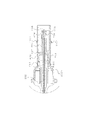
- FIG. 6 is a partial cross-sectional view showing the internal configuration of the attachment portion of the scanner / pullback unit 102 (the side connected to the base end of the drive shaft connector 202b).
- reference numeral 601 denotes a housing of the adapter device provided inside the mounting portion, which is fixed inside the head 1102 constituting the outer surface of the mounting portion.
- the housing 408 of the drive shaft connector 202b is fitted to the inner surface of the housing 601 when the connector is connected.
- the housing 601 is provided with a pair of grooves 1001 that can receive the pair of convex portions 1101 of the housing 408 connected from the groove inlet 1103 of the head 1102.
- the adapter fixing member 603 is joined to a driving force relay pipe 604 that relays the driving force of a rotation driving unit (motor) (not shown), so that after the coupling with the connector 404, the driving force relay pipe 604 is driven to rotate. 222 is transmitted.
- a pair of claws 605 are formed on the inner surface of the adapter fixing member 603.
- the pair of claws 605 are engaged with the connector 404 to firmly integrate the connector 404 and the adapter 602.
- the adapter 602 is formed with a female structure hole 606 for receiving the ferrule 406 of the connector 404, and an optical fiber end portion 607 processed into an APC type is fixed to the back of the hole 606.
- the adapter fixing member 603 includes a protective tube 608 that defines the outer surface, and a guide tube 609 that is fixed to the inner surface of the protective tube 608 and defines the inner surface of the adapter fixing member 603.
- the housing 601, the adapter 602, and the adapter fixing member 603 are collectively referred to as an adapter device. That is, the connection device is constituted by a connector device and an adapter device.
- connection device according to the present embodiment will be described.
- FIG. 7 is a diagram showing an external configuration of the connector device, where (a) is a front view, (b) is a top view, (c) is a side view, and (d) is a perspective view. is there.
- the connector device includes a connector fixing member 405 having a hollow cylindrical shape, and a connector 404 arranged inside the connector fixing member 405.
- Reference numeral 406 denotes a ferrule formed at the end of the connector 404.
- a convex portion 702 is formed in the longitudinal direction on a part of the outer peripheral surface of the connector fixing member 405.
- the proximal end portion of the convex portion 702 is a sharp end portion in order to reduce contact resistance with an end surface of an adapter fixing member 603 described later.
- the connector fixing member 405 has an outer diameter R so that the outer peripheral surface of the connector fixing member 405 slides with respect to the inner wall surface of the adapter fixing member 603 when inserted into the hollow of the adapter fixing member 603. It has been.
- a pair of slits 703 are formed at positions that do not interfere with the convex portions 702 on the outer peripheral surface of the connector fixing member 405 so as to be symmetrical.
- the side surfaces of the connectors 404 are exposed inside the slits 703, and convex portions 704 that engage with the claws 605 of the adapter fixing member 603 are formed therein.
- the connector fixing member 405 When the connector 404, the adapter 602, and the adapter fixing member 603 are integrated by the claw 605 and the convex portion 704, the connector fixing member 405 is not involved in the connection therebetween, and the connector fixing member 405 is slightly slid back and forth in the axial direction. It has a movable configuration.
- the connector fixing member 405 slides in the pulling direction via the flange 407, and at that time The round projection 705 formed at the base end of the slit 703 spreads the claw 605, releases the engagement with the convex portion 704, and can pull out the connector 404 from the adapter 602.
- FIGS. 8A and 8B are diagrams showing the external configuration of the guide tube 609 of the adapter device, where FIG. 8A is a top view, FIG. 8B is a side view, and FIG. 8C is a front view.
- the adapter device includes the adapter fixing member 603 having a hollow cylindrical shape, the adapter 602 fixed inside the adapter fixing member 603, and the housing 601.
- the adapter fixing member 603 includes a protective tube 608 and a guide tube 609. In FIG. 8, however, the structure of the guide tube 609 is illustrated alone.
- the protective tube 608 is provided for the purpose of covering the sharp tip of the guide tube 609, preventing injury to the user and damage to the connector 404, and guiding the fixing member 405 to be inserted into the guide tube 609.
- the protective tube 608 and the guide tube 609 may be molded integrally. As shown in FIG. 8, end surfaces 801 ⁇ / b> A and 801 ⁇ / b> B that are inclined end surfaces are formed on the open side of the guide tube 609.
- a notch portion 802 extending in the longitudinal direction of the adapter fixing member 603 (the axial direction of the hollow portion) is provided in a part of the end surfaces 801A and 801B of the guide tube 609. Yes.
- the notch 802 is designed with a circumferential width w so that the convex portion 702 of the connector fixing member 405 is fitted.
- the end surface 801A is an end surface extending clockwise in the circumferential direction starting from the notch 802, and the end surface 801B is an end surface extending counterclockwise.
- the end surface 801A and the end surface 801B intersect at a position of 180 degrees in the circumferential direction when viewed from the notch 802 (hereinafter, this position is referred to as a vertex).
- the end surface 801A and the end surface 801B have a symmetric relationship with respect to a plane including the notch 802 and the apex.
- the end surface 801A includes an outer wall boundary line 801A-1 that is a boundary with the outer wall and an inner wall boundary line 801A-2 that is a boundary with the inner wall.
- the end surface 801B includes an outer wall boundary line 801B-1 that is a boundary with the outer wall and an inner wall boundary line 801B-2 that is a boundary with the inner wall.
- the outer wall boundary line 801A-1 rotates 180 degrees clockwise in the circumferential direction so as to draw a spiral shape starting from the notch 802, and intersects the outer wall boundary line 801B-1 at the apex.
- the outer wall boundary line 801B-1 starts from the notch 802 and rotates 180 degrees counterclockwise in the circumferential direction so as to draw a spiral shape, and intersects the outer wall boundary line 801A-1 at the apex.
- the inner wall boundary line 801A-2 starts from the notch 802 and rotates 180 degrees clockwise in the circumferential direction so as to draw a spiral shape, and intersects the inner wall boundary line 801B-2 at the apex.
- the inner wall boundary line 801B-2 starts from the notch 802 and rotates 180 degrees in the circumferential direction so as to draw a spiral shape, and intersects the inner wall boundary line 801A-2 at the apex.
- the spiral pitches of the outer wall boundary line and the inner wall boundary line are equal.
- FIGS. 9A to 9D are views showing the operation of the connector fixing member 405 and the adapter fixing member 603 when connecting the connection device.
- the drive shaft connector 202b, the housing 601, and the protective tube 608 are omitted for the sake of explanation.
- FIG. 9 (a) when connecting, first, the drive shaft connector 202 b (not shown) is gripped, and the distal end portion of the connector fixing member 405 is inserted into the hollow portion of the adapter fixing member 603 at an arbitrary circumferential angle. To do.
- the connector fixing member 405 when the connector fixing member 405 is pressed in the insertion direction, the connector fixing member 405 further rotates. Eventually, when the convex portion 702 reaches the position of the notch portion 802, the convex portion 702 is fitted into the notch portion 802 (that is, the convex portion 702 becomes the notch portion 802 only by pressing the connector fixing member 405. Will be guided). When the connector fixing member 405 is further pushed in, the convex portion 702 is inserted straight along the notch 802, and the adapter 602 and the connector 404 are coupled.
- the tip of the convex portion 702 is fitted into the notch 802
- the circumferential movement of the connector fixing member 405 is restricted (that is, the alignment in the circumferential direction is completed), and the convex portion 702 Is inserted along the notch 802 to realize the coupling between the adapter 602 and the connector 404.
- the connector fixing member 405 is inserted into the hollow portion of the adapter fixing member 603, the connector fixing member 405 is inserted.
- the convex portion 702 is automatically guided toward the notch portion 802, and the connector fixing member 405 completes the desired alignment in the circumferential direction.
- the connecting device for connecting the optical fiber cable it is possible to easily perform the alignment in the circumferential direction for connecting the connectors. That is, the user simply moves the housing 408 of the drive shaft connector 202b linearly in the insertion direction, and the connector fixing member 405 is automatically aligned in the circumferential direction, and the desired alignment is completed.
- FIG. 10 shows a housing 601 that is a component inside the head 1102 of the mounting portion, where (a) is a top view and (b) is a perspective view.
- the housing 601 is provided with a pair of grooves 1001 at positions symmetrical with respect to the axis of the cylindrical main body.
- Each of the two groove portions 1001 is fitted with a later-described convex portion 1101 provided on the housing 408 of the connector device through the groove portion inlet 1002.
- the groove portion 1001 is inserted into the groove portion 1001, and the connector fixing member 405 is further urged in the insertion direction so that the protrusion portion 1101 is moved toward the groove portion 1001.
- the end of the groove 1001 is reached and stopped, and the adapter 602 and the connector 404 are coupled. That is, the groove part 1001 is formed so that the convex part 1101 proceeds in a rotation direction perpendicular to the insertion direction after making a U-turn from the insertion direction.
- the groove portion 1001 does not penetrate through the groove portion inlet 1002 and penetrates in the inner region, but is not limited thereto.
- FIG. 11A and 11B are external views of the connector device and the adapter device covered with the head 1102.
- FIG. 11A is a side view of the connector unit 202
- FIG. 11B is a side view of the adapter device (head 1102).
- 12 is a cross-sectional view taken along the line AA in FIG. 11, and
- FIG. 13 is a perspective view showing a state when the connector 202 and the adapter device (head 1102 are connected).
- a convex portion 1101 is arranged on the housing 408 of the connector device, and a housing 601 of the adapter device is arranged in the head 1102 of the adapter device.
- a groove portion inlet 1103 that is continuous with the groove portion 1001 of the housing 601 is provided at the inlet portion of the head 1102. That is, when the head 1102 and the connector device housing 408 are fitted together, the groove portion inlet 1103 disposed on the head 1102 and the groove portion 1001 disposed on the connector device housing 408 are positioned at the same place in the circumferential direction. To do.
- FIGS. 14 to 16 (a) is an external view showing a state in which the convex portion 1101 of the connector device housing 408 is inserted into the groove portion 1001 of the adapter device housing 601, and (b) is the connector device housing.
- the state of the elastic member when the convex portion 1101 of 408 is inserted into the groove portion 1001 of the adapter device housing 601 is shown. Note that the head 1102 is not shown for easy understanding.
- FIGS. 14A and 14B when connecting, first, the convex portion 1101 is inserted into the groove portion 1001. Next, as shown in FIG.
- the optical fiber connector is firmly connected by the elastic force of the elastic member 409, and the connector device and the adapter device are fitted to each other. be able to.
- the elastic member 409 functions as a pusher while being compressed, the optical fiber connector is not pushed excessively to be damaged, and the push-in is insufficient to cause a connection failure.
- the connector device moves slightly in the direction away from the adapter device, so that the elastic member 409 functioning as a pusher is separated from the flange 407 as a rotor, so that the rotor is Even if it rotates at high speed, it will not be damaged by contact with a non-rotating member. Therefore, the connector for the optical fiber can be easily connected.
- FIG. 17 is a view showing a connector device according to a second embodiment of the connection device of the present invention.
- the elastic member 409 that presses the disk-shaped flange 407 when the optical fiber cable is connected is a metal coil spring 1701.
- the coil spring 1701 has a cylindrical pusher 1702 at its end, and the pusher 1702 presses the disc-shaped flange 407 so that an optical fiber is connected.
- any material for forming the coil spring 1701 any material can be used as long as it can exhibit elasticity.
Priority Applications (4)
| Application Number | Priority Date | Filing Date | Title |
|---|---|---|---|
| CN200980122096.6A CN102066998B (zh) | 2008-06-20 | 2009-06-09 | 连接装置及光成像装置 |
| JP2010517856A JP5150725B2 (ja) | 2008-06-20 | 2009-06-09 | 接続装置および光イメージング装置 |
| EP09766551.7A EP2290416B1 (en) | 2008-06-20 | 2009-06-09 | Connection device and optical imaging device |
| US12/973,245 US8322932B2 (en) | 2008-06-20 | 2010-12-20 | Coupling device and optical imaging device |
Applications Claiming Priority (2)
| Application Number | Priority Date | Filing Date | Title |
|---|---|---|---|
| JP2008161062 | 2008-06-20 | ||
| JP2008-161062 | 2008-06-20 |
Related Child Applications (1)
| Application Number | Title | Priority Date | Filing Date |
|---|---|---|---|
| US12/973,245 Continuation US8322932B2 (en) | 2008-06-20 | 2010-12-20 | Coupling device and optical imaging device |
Publications (1)
| Publication Number | Publication Date |
|---|---|
| WO2009154103A1 true WO2009154103A1 (ja) | 2009-12-23 |
Family
ID=41434019
Family Applications (1)
| Application Number | Title | Priority Date | Filing Date |
|---|---|---|---|
| PCT/JP2009/060518 WO2009154103A1 (ja) | 2008-06-20 | 2009-06-09 | 接続装置および光イメージング装置 |
Country Status (5)
| Country | Link |
|---|---|
| US (1) | US8322932B2 (zh) |
| EP (1) | EP2290416B1 (zh) |
| JP (1) | JP5150725B2 (zh) |
| CN (1) | CN102066998B (zh) |
| WO (1) | WO2009154103A1 (zh) |
Cited By (6)
| Publication number | Priority date | Publication date | Assignee | Title |
|---|---|---|---|---|
| JP2011194064A (ja) * | 2010-03-19 | 2011-10-06 | Terumo Corp | 取付装置及び光画像診断装置 |
| JP5771597B2 (ja) * | 2010-03-16 | 2015-09-02 | テルモ株式会社 | ガイドワイヤおよびカテーテル組立体 |
| WO2015141134A1 (ja) * | 2014-03-19 | 2015-09-24 | テルモ株式会社 | 光画像診断装置及びそれに用いるカテーテル |
| JP2015177919A (ja) * | 2014-03-19 | 2015-10-08 | テルモ株式会社 | 光画像診断装置及びそれに用いるカテーテル |
| JP2018157938A (ja) * | 2017-03-22 | 2018-10-11 | テルモ株式会社 | 画像診断装置 |
| JP2021065725A (ja) * | 2021-01-21 | 2021-04-30 | テルモ株式会社 | 画像診断装置 |
Families Citing this family (39)
| Publication number | Priority date | Publication date | Assignee | Title |
|---|---|---|---|---|
| US9125562B2 (en) | 2009-07-01 | 2015-09-08 | Avinger, Inc. | Catheter-based off-axis optical coherence tomography imaging system |
| US9498600B2 (en) | 2009-07-01 | 2016-11-22 | Avinger, Inc. | Atherectomy catheter with laterally-displaceable tip |
| WO2010129075A1 (en) | 2009-04-28 | 2010-11-11 | Avinger, Inc. | Guidewire support catheter |
| EP4145111A1 (en) | 2009-05-28 | 2023-03-08 | Avinger, Inc. | Optical coherence tomography for biological imaging |
| US10548478B2 (en) | 2010-07-01 | 2020-02-04 | Avinger, Inc. | Balloon atherectomy catheters with imaging |
| WO2014039096A1 (en) | 2012-09-06 | 2014-03-13 | Avinger, Inc. | Re-entry stylet for catheter |
| US11382653B2 (en) | 2010-07-01 | 2022-07-12 | Avinger, Inc. | Atherectomy catheter |
| US10363062B2 (en) | 2011-10-17 | 2019-07-30 | Avinger, Inc. | Atherectomy catheters and non-contact actuation mechanism for catheters |
| US9949754B2 (en) | 2011-03-28 | 2018-04-24 | Avinger, Inc. | Occlusion-crossing devices |
| JP6205344B2 (ja) | 2011-03-28 | 2017-09-27 | アビンガー・インコーポレイテッドAvinger, Inc. | 閉塞クロッシング用デバイス、撮像用デバイスおよびアテローム切除用デバイス |
| JP5864182B2 (ja) | 2011-09-28 | 2016-02-17 | テルモ株式会社 | モータ駆動装置及び画像診断装置 |
| US9345406B2 (en) | 2011-11-11 | 2016-05-24 | Avinger, Inc. | Occlusion-crossing devices, atherectomy devices, and imaging |
| US9345398B2 (en) | 2012-05-14 | 2016-05-24 | Avinger, Inc. | Atherectomy catheter drive assemblies |
| WO2013172970A1 (en) | 2012-05-14 | 2013-11-21 | Avinger, Inc. | Atherectomy catheters with imaging |
| US9557156B2 (en) | 2012-05-14 | 2017-01-31 | Avinger, Inc. | Optical coherence tomography with graded index fiber for biological imaging |
| US11284916B2 (en) | 2012-09-06 | 2022-03-29 | Avinger, Inc. | Atherectomy catheters and occlusion crossing devices |
| US9498247B2 (en) | 2014-02-06 | 2016-11-22 | Avinger, Inc. | Atherectomy catheters and occlusion crossing devices |
| US9854979B2 (en) | 2013-03-15 | 2018-01-02 | Avinger, Inc. | Chronic total occlusion crossing devices with imaging |
| CN105228514B (zh) | 2013-03-15 | 2019-01-22 | 阿维格公司 | 光学压力传感器组件 |
| WO2014142954A1 (en) | 2013-03-15 | 2014-09-18 | Avinger, Inc. | Tissue collection device for catheter |
| US10130386B2 (en) | 2013-07-08 | 2018-11-20 | Avinger, Inc. | Identification of elastic lamina to guide interventional therapy |
| WO2015016892A1 (en) * | 2013-07-31 | 2015-02-05 | Corning Cable Systems Llc | Fiber optic connector sub-assemblies having a front-loading locking ferrule holder and related fiber optic components, devices and methods |
| US9618704B2 (en) | 2013-07-31 | 2017-04-11 | Corning Optical Communications LLC | Fiber optic connector sub-assemblies having a front-loading locking ferrule holder and related fiber optic components, devices and methods |
| MX2016010141A (es) | 2014-02-06 | 2017-04-06 | Avinger Inc | Cateteres de aterectomia y dispositivos de cruce de oclusion. |
| US10357277B2 (en) | 2014-07-08 | 2019-07-23 | Avinger, Inc. | High speed chronic total occlusion crossing devices |
| EP3181035B1 (en) * | 2014-08-14 | 2023-09-13 | Terumo Kabushiki Kaisha | Connection device and imaging device provided with said connection device |
| EP4035586A1 (en) | 2015-04-16 | 2022-08-03 | Gentuity LLC | Micro-optic probes for neurology |
| EP3319680A4 (en) * | 2015-07-06 | 2018-12-19 | Avinger, Inc. | Self-alignment mechanism for imaging catheter and drive assembly |
| US10568520B2 (en) | 2015-07-13 | 2020-02-25 | Avinger, Inc. | Micro-molded anamorphic reflector lens for image guided therapeutic/diagnostic catheters |
| CN104958065B (zh) * | 2015-07-16 | 2017-10-27 | 南京沃福曼医疗科技有限公司 | 一种血管内断层成像导管 |
| JP6981967B2 (ja) | 2015-08-31 | 2021-12-17 | ジェンテュイティ・リミテッド・ライアビリティ・カンパニーGentuity, LLC | 撮像プローブおよびデリバリデバイスを含む撮像システム |
| CN105684866A (zh) * | 2015-12-04 | 2016-06-22 | 杜晓华 | 一种自动灌溉方便施肥的立体化种菜设备 |
| AU2017212407A1 (en) | 2016-01-25 | 2018-08-02 | Avinger, Inc. | OCT imaging catheter with lag correction |
| CN108882948A (zh) | 2016-04-01 | 2018-11-23 | 阿维格公司 | 具有锯齿状切割器的旋切术导管 |
| JP2019518543A (ja) | 2016-06-03 | 2019-07-04 | アビンガー・インコーポレイテッドAvinger, Inc. | 着脱可能な遠位端部を有するカテーテル装置 |
| EP3478190B1 (en) | 2016-06-30 | 2023-03-15 | Avinger, Inc. | Atherectomy catheter with shapeable distal tip |
| JP7160935B2 (ja) | 2017-11-28 | 2022-10-25 | ジェンテュイティ・リミテッド・ライアビリティ・カンパニー | 撮像システム |
| US11793400B2 (en) | 2019-10-18 | 2023-10-24 | Avinger, Inc. | Occlusion-crossing devices |
| WO2022123669A1 (ja) | 2020-12-09 | 2022-06-16 | デラウェーブ株式会社 | 光断層撮影装置に用いられる接続機構及びロック機構 |
Citations (7)
| Publication number | Priority date | Publication date | Assignee | Title |
|---|---|---|---|---|
| JPH0437538B2 (zh) | 1980-07-18 | 1992-06-19 | Tokyo Shibaura Electric Co | |
| JPH0470608U (zh) * | 1990-10-29 | 1992-06-23 | ||
| JPH0491315U (zh) * | 1990-12-26 | 1992-08-10 | ||
| JPH08327855A (ja) * | 1994-06-24 | 1996-12-13 | At & T Corp | 光ファイバコネクタ |
| JP2001507251A (ja) | 1996-11-25 | 2001-06-05 | ボストン サイエンティフィック コーポレイション | 光ファイバを回転可能に接続する装置 |
| JP2005533533A (ja) | 2001-10-24 | 2005-11-10 | シメッド ライフ システムズ インコーポレイテッド | 光カテーテルコネクタ |
| WO2008023741A1 (fr) | 2006-08-24 | 2008-02-28 | Terumo Kabushiki Kaisha | Accouplement de dispositif, dispositif auxiliaire et élément de fixation d'adaptateur |
Family Cites Families (4)
| Publication number | Priority date | Publication date | Assignee | Title |
|---|---|---|---|---|
| US4898446A (en) * | 1988-10-28 | 1990-02-06 | American Telephone And Telegraph Company, At&T Bell Laboratories | Optical fiber connector |
| US5668904A (en) * | 1996-07-25 | 1997-09-16 | Northwest Fiberoptic Technologies Inc. | Fiber optic cable connector apparatus and method |
| EP1793250A4 (en) * | 2004-08-20 | 2007-11-14 | Sumitomo Electric Industries | OPTICAL CONNECTOR AND METHOD FOR ASSEMBLING OPTICAL CONNECTOR |
| US7346256B2 (en) * | 2004-11-04 | 2008-03-18 | Panduit Corp. | Re-terminable LC connector assembly and cam termination tool |
-
2009
- 2009-06-09 WO PCT/JP2009/060518 patent/WO2009154103A1/ja active Application Filing
- 2009-06-09 EP EP09766551.7A patent/EP2290416B1/en active Active
- 2009-06-09 JP JP2010517856A patent/JP5150725B2/ja active Active
- 2009-06-09 CN CN200980122096.6A patent/CN102066998B/zh active Active
-
2010
- 2010-12-20 US US12/973,245 patent/US8322932B2/en active Active
Patent Citations (7)
| Publication number | Priority date | Publication date | Assignee | Title |
|---|---|---|---|---|
| JPH0437538B2 (zh) | 1980-07-18 | 1992-06-19 | Tokyo Shibaura Electric Co | |
| JPH0470608U (zh) * | 1990-10-29 | 1992-06-23 | ||
| JPH0491315U (zh) * | 1990-12-26 | 1992-08-10 | ||
| JPH08327855A (ja) * | 1994-06-24 | 1996-12-13 | At & T Corp | 光ファイバコネクタ |
| JP2001507251A (ja) | 1996-11-25 | 2001-06-05 | ボストン サイエンティフィック コーポレイション | 光ファイバを回転可能に接続する装置 |
| JP2005533533A (ja) | 2001-10-24 | 2005-11-10 | シメッド ライフ システムズ インコーポレイテッド | 光カテーテルコネクタ |
| WO2008023741A1 (fr) | 2006-08-24 | 2008-02-28 | Terumo Kabushiki Kaisha | Accouplement de dispositif, dispositif auxiliaire et élément de fixation d'adaptateur |
Cited By (9)
| Publication number | Priority date | Publication date | Assignee | Title |
|---|---|---|---|---|
| JP5771597B2 (ja) * | 2010-03-16 | 2015-09-02 | テルモ株式会社 | ガイドワイヤおよびカテーテル組立体 |
| US9943667B2 (en) | 2010-03-16 | 2018-04-17 | Terumo Kabushiki Kaisha | Guide wire and catheter assembly |
| JP2011194064A (ja) * | 2010-03-19 | 2011-10-06 | Terumo Corp | 取付装置及び光画像診断装置 |
| WO2015141134A1 (ja) * | 2014-03-19 | 2015-09-24 | テルモ株式会社 | 光画像診断装置及びそれに用いるカテーテル |
| JP2015177919A (ja) * | 2014-03-19 | 2015-10-08 | テルモ株式会社 | 光画像診断装置及びそれに用いるカテーテル |
| JPWO2015141134A1 (ja) * | 2014-03-19 | 2017-04-06 | テルモ株式会社 | 光画像診断装置及びそれに用いるカテーテル |
| JP2018157938A (ja) * | 2017-03-22 | 2018-10-11 | テルモ株式会社 | 画像診断装置 |
| JP2021065725A (ja) * | 2021-01-21 | 2021-04-30 | テルモ株式会社 | 画像診断装置 |
| JP7223042B2 (ja) | 2021-01-21 | 2023-02-15 | テルモ株式会社 | 画像診断装置 |
Also Published As
| Publication number | Publication date |
|---|---|
| JP5150725B2 (ja) | 2013-02-27 |
| EP2290416B1 (en) | 2020-03-18 |
| US8322932B2 (en) | 2012-12-04 |
| EP2290416A4 (en) | 2017-12-06 |
| JPWO2009154103A1 (ja) | 2011-11-24 |
| EP2290416A1 (en) | 2011-03-02 |
| CN102066998A (zh) | 2011-05-18 |
| US20120002928A1 (en) | 2012-01-05 |
| CN102066998B (zh) | 2014-04-16 |
Similar Documents
| Publication | Publication Date | Title |
|---|---|---|
| JP5150725B2 (ja) | 接続装置および光イメージング装置 | |
| JP5139298B2 (ja) | 接続装置および補助装置ならびにアダプタ固定部材 | |
| JP5563582B2 (ja) | 画像診断装置 | |
| EP3181035B1 (en) | Connection device and imaging device provided with said connection device | |
| EP3378407B1 (en) | Imaging apparatus for diagnosis | |
| JP7026202B2 (ja) | イメージングカテーテルおよびイメージングカテーテルの作動方法 | |
| JP5171354B2 (ja) | 生体内画像診断プローブ | |
| JP5296867B2 (ja) | 光伝送装置 | |
| JP2016041111A (ja) | 接続装置およびその接続装置を備えるイメージング装置 | |
| JP5451289B2 (ja) | カテーテルおよび延長器具 | |
| JP6563902B2 (ja) | 光画像診断装置及びそれに用いるカテーテル | |
| JP2016206486A (ja) | 光プローブおよび光プローブの取り付け方法 | |
| JP2011194064A (ja) | 取付装置及び光画像診断装置 | |
| JP6210912B2 (ja) | 光画像診断装置及びそれに用いるカテーテル | |
| JP2000354582A (ja) | 内視鏡装置 | |
| JP2016154808A (ja) | カテーテル及び駆動装置 |
Legal Events
| Date | Code | Title | Description |
|---|---|---|---|
| WWE | Wipo information: entry into national phase |
Ref document number: 200980122096.6 Country of ref document: CN |
|
| 121 | Ep: the epo has been informed by wipo that ep was designated in this application |
Ref document number: 09766551 Country of ref document: EP Kind code of ref document: A1 |
|
| WWE | Wipo information: entry into national phase |
Ref document number: 2010517856 Country of ref document: JP |
|
| WWE | Wipo information: entry into national phase |
Ref document number: 2009766551 Country of ref document: EP |
|
| NENP | Non-entry into the national phase |
Ref country code: DE |