EP3478190B1 - Atherectomy catheter with shapeable distal tip - Google Patents
Atherectomy catheter with shapeable distal tip Download PDFInfo
- Publication number
- EP3478190B1 EP3478190B1 EP17821409.4A EP17821409A EP3478190B1 EP 3478190 B1 EP3478190 B1 EP 3478190B1 EP 17821409 A EP17821409 A EP 17821409A EP 3478190 B1 EP3478190 B1 EP 3478190B1
- Authority
- EP
- European Patent Office
- Prior art keywords
- spine
- annular
- catheter
- curved portion
- atherectomy catheter
- Prior art date
- Legal status (The legal status is an assumption and is not a legal conclusion. Google has not performed a legal analysis and makes no representation as to the accuracy of the status listed.)
- Active
Links
- 238000010030 laminating Methods 0.000 claims description 10
- 229920000642 polymer Polymers 0.000 claims description 8
- 239000002184 metal Substances 0.000 claims description 4
- 210000001367 artery Anatomy 0.000 description 7
- 239000000463 material Substances 0.000 description 7
- 230000007246 mechanism Effects 0.000 description 7
- 201000001320 Atherosclerosis Diseases 0.000 description 5
- 238000000034 method Methods 0.000 description 5
- 230000006835 compression Effects 0.000 description 4
- 238000007906 compression Methods 0.000 description 4
- HLXZNVUGXRDIFK-UHFFFAOYSA-N nickel titanium Chemical compound [Ti].[Ti].[Ti].[Ti].[Ti].[Ti].[Ti].[Ti].[Ti].[Ti].[Ti].[Ni].[Ni].[Ni].[Ni].[Ni].[Ni].[Ni].[Ni].[Ni].[Ni].[Ni].[Ni].[Ni].[Ni] HLXZNVUGXRDIFK-UHFFFAOYSA-N 0.000 description 4
- 229910001000 nickel titanium Inorganic materials 0.000 description 4
- 229910001220 stainless steel Inorganic materials 0.000 description 4
- 239000010935 stainless steel Substances 0.000 description 4
- 238000001356 surgical procedure Methods 0.000 description 3
- 210000004204 blood vessel Anatomy 0.000 description 2
- 210000004556 brain Anatomy 0.000 description 2
- 201000010099 disease Diseases 0.000 description 2
- 208000037265 diseases, disorders, signs and symptoms Diseases 0.000 description 2
- 230000002708 enhancing effect Effects 0.000 description 2
- 210000002216 heart Anatomy 0.000 description 2
- 238000003475 lamination Methods 0.000 description 2
- 239000013307 optical fiber Substances 0.000 description 2
- 230000007505 plaque formation Effects 0.000 description 2
- 206010020772 Hypertension Diseases 0.000 description 1
- 208000024248 Vascular System injury Diseases 0.000 description 1
- 208000012339 Vascular injury Diseases 0.000 description 1
- 230000035508 accumulation Effects 0.000 description 1
- 238000009825 accumulation Methods 0.000 description 1
- 230000004913 activation Effects 0.000 description 1
- 230000032683 aging Effects 0.000 description 1
- 238000013459 approach Methods 0.000 description 1
- 210000000617 arm Anatomy 0.000 description 1
- QVGXLLKOCUKJST-UHFFFAOYSA-N atomic oxygen Chemical compound [O] QVGXLLKOCUKJST-UHFFFAOYSA-N 0.000 description 1
- 238000005452 bending Methods 0.000 description 1
- 239000008280 blood Substances 0.000 description 1
- 210000004369 blood Anatomy 0.000 description 1
- 210000001715 carotid artery Anatomy 0.000 description 1
- 230000008859 change Effects 0.000 description 1
- 230000008602 contraction Effects 0.000 description 1
- 208000029078 coronary artery disease Diseases 0.000 description 1
- 210000004351 coronary vessel Anatomy 0.000 description 1
- 230000037213 diet Effects 0.000 description 1
- 235000005911 diet Nutrition 0.000 description 1
- 229940079593 drug Drugs 0.000 description 1
- 239000003814 drug Substances 0.000 description 1
- 230000007717 exclusion Effects 0.000 description 1
- 238000003384 imaging method Methods 0.000 description 1
- 230000003993 interaction Effects 0.000 description 1
- 210000003734 kidney Anatomy 0.000 description 1
- 210000002414 leg Anatomy 0.000 description 1
- 239000000203 mixture Substances 0.000 description 1
- 229910052760 oxygen Inorganic materials 0.000 description 1
- 239000001301 oxygen Substances 0.000 description 1
- 238000012856 packing Methods 0.000 description 1
- 210000004197 pelvis Anatomy 0.000 description 1
- 230000007406 plaque accumulation Effects 0.000 description 1
- 238000005476 soldering Methods 0.000 description 1
- 239000007787 solid Substances 0.000 description 1
Images


Classifications
-
- A—HUMAN NECESSITIES
- A61—MEDICAL OR VETERINARY SCIENCE; HYGIENE
- A61B—DIAGNOSIS; SURGERY; IDENTIFICATION
- A61B17/00—Surgical instruments, devices or methods, e.g. tourniquets
- A61B17/32—Surgical cutting instruments
- A61B17/3205—Excision instruments
- A61B17/3207—Atherectomy devices working by cutting or abrading; Similar devices specially adapted for non-vascular obstructions
- A61B17/320783—Atherectomy devices working by cutting or abrading; Similar devices specially adapted for non-vascular obstructions through side-hole, e.g. sliding or rotating cutter inside catheter
-
- A—HUMAN NECESSITIES
- A61—MEDICAL OR VETERINARY SCIENCE; HYGIENE
- A61D—VETERINARY INSTRUMENTS, IMPLEMENTS, TOOLS, OR METHODS
- A61D1/00—Surgical instruments for veterinary use
- A61D1/02—Trocars or cannulas for teats; Vaccination appliances
-
- A—HUMAN NECESSITIES
- A61—MEDICAL OR VETERINARY SCIENCE; HYGIENE
- A61B—DIAGNOSIS; SURGERY; IDENTIFICATION
- A61B17/00—Surgical instruments, devices or methods, e.g. tourniquets
- A61B17/00234—Surgical instruments, devices or methods, e.g. tourniquets for minimally invasive surgery
- A61B2017/00292—Surgical instruments, devices or methods, e.g. tourniquets for minimally invasive surgery mounted on or guided by flexible, e.g. catheter-like, means
- A61B2017/003—Steerable
- A61B2017/00305—Constructional details of the flexible means
- A61B2017/00309—Cut-outs or slits
-
- A—HUMAN NECESSITIES
- A61—MEDICAL OR VETERINARY SCIENCE; HYGIENE
- A61B—DIAGNOSIS; SURGERY; IDENTIFICATION
- A61B17/00—Surgical instruments, devices or methods, e.g. tourniquets
- A61B17/00234—Surgical instruments, devices or methods, e.g. tourniquets for minimally invasive surgery
- A61B2017/00292—Surgical instruments, devices or methods, e.g. tourniquets for minimally invasive surgery mounted on or guided by flexible, e.g. catheter-like, means
- A61B2017/003—Steerable
- A61B2017/00318—Steering mechanisms
- A61B2017/00331—Steering mechanisms with preformed bends
-
- A—HUMAN NECESSITIES
- A61—MEDICAL OR VETERINARY SCIENCE; HYGIENE
- A61B—DIAGNOSIS; SURGERY; IDENTIFICATION
- A61B17/00—Surgical instruments, devices or methods, e.g. tourniquets
- A61B2017/00681—Aspects not otherwise provided for
- A61B2017/00738—Aspects not otherwise provided for part of the tool being offset with respect to a main axis, e.g. for better view for the surgeon
-
- A—HUMAN NECESSITIES
- A61—MEDICAL OR VETERINARY SCIENCE; HYGIENE
- A61B—DIAGNOSIS; SURGERY; IDENTIFICATION
- A61B17/00—Surgical instruments, devices or methods, e.g. tourniquets
- A61B17/32—Surgical cutting instruments
- A61B17/3205—Excision instruments
- A61B17/3207—Atherectomy devices working by cutting or abrading; Similar devices specially adapted for non-vascular obstructions
- A61B17/320783—Atherectomy devices working by cutting or abrading; Similar devices specially adapted for non-vascular obstructions through side-hole, e.g. sliding or rotating cutter inside catheter
- A61B2017/320791—Atherectomy devices working by cutting or abrading; Similar devices specially adapted for non-vascular obstructions through side-hole, e.g. sliding or rotating cutter inside catheter with cutter extending outside the cutting window
-
- A—HUMAN NECESSITIES
- A61—MEDICAL OR VETERINARY SCIENCE; HYGIENE
- A61M—DEVICES FOR INTRODUCING MEDIA INTO, OR ONTO, THE BODY; DEVICES FOR TRANSDUCING BODY MEDIA OR FOR TAKING MEDIA FROM THE BODY; DEVICES FOR PRODUCING OR ENDING SLEEP OR STUPOR
- A61M25/00—Catheters; Hollow probes
- A61M25/0043—Catheters; Hollow probes characterised by structural features
- A61M25/0054—Catheters; Hollow probes characterised by structural features with regions for increasing flexibility
-
- A—HUMAN NECESSITIES
- A61—MEDICAL OR VETERINARY SCIENCE; HYGIENE
- A61M—DEVICES FOR INTRODUCING MEDIA INTO, OR ONTO, THE BODY; DEVICES FOR TRANSDUCING BODY MEDIA OR FOR TAKING MEDIA FROM THE BODY; DEVICES FOR PRODUCING OR ENDING SLEEP OR STUPOR
- A61M25/00—Catheters; Hollow probes
- A61M25/01—Introducing, guiding, advancing, emplacing or holding catheters
- A61M25/0105—Steering means as part of the catheter or advancing means; Markers for positioning
- A61M25/0133—Tip steering devices
- A61M25/0138—Tip steering devices having flexible regions as a result of weakened outer material, e.g. slots, slits, cuts, joints or coils
Definitions
- Described herein are devices for treatment of an occluded body lumen, such as for the removal of occlusive materials from blood vessels.
- atherectomy catheters that are adapted to easily maneuver against tissue and plaque buildup within vessels for debulking.
- Atherosclerosis is disease in which accumulation of atheromatous materials builds up inside a person's arteries. Atherosclerosis occurs as part of the natural aging process, but may also occur due to a person's diet, hypertension, vascular injury, heredity, and so forth. Atherosclerosis can affect any artery in the body, including arteries in the heart, brain, arms, legs, pelvis, and kidneys. Atherosclerosis deposits may vary in their properties as well. Some deposits are relatively soft, other types may be fibrous, some are calcified, or a combination of all three. Based on the location of the plaque accumulation, different diseases may develop. For example, coronary heart disease occurs when plaque builds up in the coronary arteries, which supply oxygenated blood to the heart. If plaque buildup blocks the carotid artery, arteries located on each side of the neck that supply oxygen to the brain, a stroke may be the result.
- Atherosclerosis may be treated in a number of ways including medication, bypass surgery, and catheter-based approaches. Atherectomy procedures involve excising or dislodging materials that block a blood vessel. Many atherectomy catheters typically have a substantially straight central axis. However, atherectomy catheters having a straight profile may be difficult to maneuver close enough to the inner surface of the arterial walls to remove all plaque buildup. Moreover, plaque removal can be complicated with such straight profile catheters when plaque formations accumulate in the curves and more tortuous portions of an artery.
- US 2015/0141816 discloses an atherectomy catheter that includes an elongate flexible catheter body, an elongate deflectable distal tip coupled to the catheter body at a hinge point, a rotatable cutter near the distal end of the catheter body, and a drive shaft extending within the catheter body and configured to rotate the cutter.
- the atherectomy catheter further includes an optical fiber that extends through the drive shaft substantially on-axis with the catheter body. The optical fiber is attached to the cutter and is configured to rotate with the drive shaft.
- the atherectomy catheter further includes a wedge that is configured to deflect the distal tip away from the catheter body at the hinge point upon axial movement of the drive shaft.
- WO 2012/123737 discloses a steerable element for use in surgery.
- the steerable element comprises: an inflatable member; and an elongate frame azimuthally surrounding said inflatable member.
- the inflatable member is configured to press against said elongate frame on inflation so as to cause a change in the curvature of said elongate frame.
- the atherectomy catheters described herein address some of these challenges.
- an atherectomy catheter for use in a vessel that includes an elongate catheter body and an annular cutter.
- the elongate catheter body includes a fixed jog section with a pre-set curvature and a flexible section that has a greater flexibility than a remainder of the elongate catheter body.
- the fixed jog section and flexible section are formed of a frame including a plurality of circumferential slits therein.
- the frame in the fixed jog section can further include a longitudinal spine extending therethrough that does not have slits.
- the atherectomy catheter can further include a cutting window through which the annular cutter extends.
- the cutting window can be positioned distal of the fixed jog section and the flexible section so as to urge the cutter into the vessel.
- the atherectomy catheter can further include at least one laminating layer positioned over or under the frame of the fixed jog section.
- the laminating layer can be made of a polymer.
- the frame can be made of metal.
- the plurality of circumferential slits can be arranged in a repeating pattern.
- the fixed jog section can form an angle of 130° to 160° in the elongate catheter body.
- the frame can further include an annular spine without slits that extends between the fixed jog section and the flexible section.
- the flexible section can be configured to passively bend to angles of 130°-160°.
- the present invention provides an atherectomy catheter for use in a vessel according to claim 1.
- the atherectomy catheter of the invention includes one or more of the following features.
- the plurality of annular spines includes a first annular spine, a second annular spine, and a third annular spine.
- the longitudinal proximal spine connects the first annular spine and the second annular spine
- the longitudinal distal spine connects the second annular spine and the third annular spine.
- the atherectomy catheter can further include a cutting window through which the annular cutter extends.
- the cutting window can be positioned distal of the curved portion and on an outer circumference of the s-shaped curve so as to urge the cutter into the vessel.
- the s-shaped curved portion can be configured to be activated by pulling or pushing on a shaft of the atherectomy catheter.
- the atherectomy catheter can further include at least one laminating layer positioned over or under the frame.
- the laminating layer can be made of a polymer.
- the frame can be made of metal.
- the longitudinal proximal spine can form a first angle, and the longitudinal distal spine can form a second angle.
- the first and second angles can extend in opposite directions, and the first angle can be between 140 and 160 degrees and the second angle can be between 140 and 160 degrees.
- an atherectomy catheter for use in a vessel that includes an elongate catheter body, an annular cutter, and an s-shaped curved portion in the elongate catheter body.
- the curved portion includes a frame having a proximal section and a distal section.
- the proximal section has a plurality of circumferential proximal slits and a longitudinal proximal spine without slits, and the distal section having a plurality of circumferential distal slits and a longitudinal distal spine without slits.
- the longitudinal proximal spine is positioned approximately 180 degrees away from the longitudinal distal spine.
- the atherectomy catheter can include one or more of the following features.
- the atherectomy catheter can further include a cutting window through which the annular cutter extends.
- the cutting window can be positioned distal of the distal section and on an outer circumference of the s-shaped curve so as to urge the cutter into the vessel.
- the s-shaped curved portion can be configured to be activated by pulling or pushing on a shaft of the atherectomy catheter.
- the atherectomy catheter can further include at least one laminating layer positioned over or under the frame.
- the laminating layer can be made of a polymer.
- the frame can be made of metal.
- the plurality of circumferential proximal slits can be arranged in a first repeating pattern, and the plurality of circumferential distal slits can be arranged in a second repeating pattern.
- the first repeating pattern and the second repeating pattern can be circumferentially offset from one another.
- the distal longitudinal spine can be positioned adjacent to an exposed portion of the cutter.
- the distal longitudinal spine can be on a same side of the elongate catheter body as the exposed portion of the cutter.
- the proximal section can form a first angle, and the distal section forms a second angle.
- the first and second angles can extend in opposite directions, and the first angle can be between 140 and 160 degrees and the second angle can be between 140 and 160 degrees.
- the frame can further include an annular spine without slits extending between the proximal section and the distal section.
- an atherectomy catheter having an elongate body with a curved distal portion, a nosecone and a rotatable annular cutter.
- the curved portion (which can otherwise be called a bent/bendable portion or jog mechanism) can advantageously be used to push the cutter up against the vessel wall to enhance the efficiency of cutting.
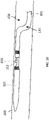
- FIGS. 1A and 1B show an exemplary atherectomy catheter 100 having a curved portion along the elongate catheter body.
- the atherectomy catheter 100 can include a catheter body 101 with a curved portion 133, a rotatable annular cutter 103 at a distal end of the catheter body 101, and a nosecone 105 at a distal end of the catheter body 101.
- the nosecone 105 can include a cutting window 107 configured to allow the cutter 103 to cut therethrough.
- the catheter 101 can further include a curved portion 133 in the catheter body 101 to radially push the cutter 103 against the vessel wall.
- the curved portion 133 can be a fixed jog (i.e., have a pre-set shape). Further, the curved portion can be curved or bent such that the cutting window 107 is on the radially outermost portion of the curved portion 133 (thereby allowing the cutting window 107 to be urged against a vessel wall in use).
- the curved portion 133 can be pre-formed, for example, by using pre-deflected shaped-set nitinol ribbon segments embedded in the outer shaft.
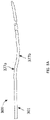
- the curved portion 133 can have two inflection points 155, 166 of opposite curvature (i.e., one curving up and the other curving down) so as to form an approximate "s" shape.
- the s-shape can be configured such that a distal end of the catheter body 101 is offset from, but substantially parallel to, a proximal end of the catheter body 101.
- the distal end and proximal ends of the catheter body 101 can be at a slight angle to one another so as to control the angle of cutter engagement with the vessel wall.
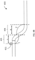
- the "s-shape" of the curved portion 133 can include a proximal section 137 have a length b that extends from the center of the distal inflection point 155 to the center of the proximal inflection point 166. Further, the curved portion 133 can include a distal section 135 having a length a that extends from the cutting edge 112 to the center of the distal inflection point 155.
- distal angle 1 at the distal end of the "s-shape" and a proximal angle 2 at the proximal end of the "s-shape.”
- These lengths ( a, b ) and angles (1, 2) can be tuned to achieve the desired jog or offset in order to obtain optimum apposition to tissue walls.
- the length a can be shorter than the length b to ensure that the cutter is as close to the angle 1 as possible, thereby providing better apposition of the cutter 303.
- the angles 1 and 2 can be between 120 and 180 degrees, such as between 140 and 160 degrees.
- the length a is between 5 and 10mm
- the length b is between 10 and 15mm
- the angle 1 is 140 degrees
- angle 2 is 160 degrees for a catheter configured to be used in a vessel having a 2.5-4mm diameter.
- the curved portion 133 can advantageously radially push the distal end of the catheter against a vessel wall 200, thereby enabling optimized cutting and/or imaging of the vessel as shown in FIG. 1B .
- FIGS. 3A-3B show another exemplary catheter 300 that includes a curved portion 333 in the catheter body that urges the atherectomy cutter against the vessel wall.
- the curved portion 333 can have similar dimensions and features as curved portion 133.
- the curved portion 333 can be a user-activated jog.
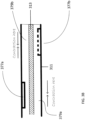
- the catheter 300 can be deflected into a curved portion 333 by tensile and compressive interaction between an inner shaft 313 (which can be a drive shaft for a cutter) and outer shaft 311 that are fixed together at the distal end but free to move relative to one another at the proximal end.
- the outer shaft 311 can include stiffening members 377a,b, such as nitinol or stainless steel, stiffening members, configured to bias the deflection to a set shape.
- stiffening members 377a,b such as nitinol or stainless steel, stiffening members, configured to bias the deflection to a set shape.
- the portions 379a,b of the outer shaft opposite to the stiffening members 377a,b will contract.
- the contraction of the two portions 379a, 379b will result in an s-shape similar to the catheter 100 shown in FIG.
- the catheter will deflect into jog or s-shaped configuration where the distal end of the shaft is offset and parallel to the main shaft body. It is to be understood that other numbers and arrangements of stiffening members are possible, as are other resulting jog shapes.
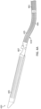
- FIGS. 4A-4B Another atherectomy catheter 400 including a user-activated curved portion 433 is shown in FIGS. 4A-4B .
- the atherectomy catheter 400 includes an elongate body 401, a nosecone 405 attached thereto, and a cutting window 407 configured to expose an annular cutter 411 therethrough.
- the catheter 400 includes a curved portion 433.
- the curved portion 433 includes curved sections 425, 426 of opposite curvatures (i.e., one curving up and the other curving down) so as to form an approximate s-shape.
- the s-shape can be configured such that the distal end of the catheter body 401 and/or the nosecone 405 is offset from, but substantially parallel to, a proximal end of the catheter body 401.
- the distal end of the elongate body 401 and/or the nosecone 405 forms an angle relative to a proximal end of the catheter body 401.
- the "s-shape" of the jog 433 can have a proximal curved section 426 and a distal curved section 425 having a length c. Further, there can be distal angle 1 at the distal end of the "s-shape” and a proximal angle 2 at the proximal end of the "s-shape.”
- the lengths (c, d ) and angles ( 1 , 2) of the jog 433 can be tuned to achieve the desired jog or offset in order to obtain optimum apposition to tissue walls.
- the angles 1 and 2 can be between 120 and 175 degrees, such as between 140 and 160 degrees.
- the length d of the proximal section 426 is greater than the length c of the distal section 425.
- the length c is 5mm
- the length d is 8mm
- the angles 1 and 2 are 150 degrees for a catheter configured to be used in a vessel having a 2.5-4mm diameter.
- the curved portion 433 can be a configured to adopt the s-shape during use of the catheter, as described above with respect to curved portion 333.
- the curved portion 533 can include a frame (e.g., made of Nitinol or stainless steel) including a series of circumferential slits 550 (e.g., laser cuts) that are patterned along the circumference of the elongate body 501 within the curved sections 525, 526.
- the frame of the curved sections 525, 526 can also include a longitudinal spine 560a,b extending therethrough.
- the longitudinal spines 560a,b can be positioned approximately 180 degrees away from one another (i.e., on opposites sides of the elongate body 501) and extend substantially parallel to the longitudinal central axis of the elongate body 501.
- the frame can further include a circumferential spine 561 separating the two curved sections 525, 526.
- Each spine 560a,b and 561 is formed of a substantially solid piece of material that does not include slits therein.
- the longitudinal spines 560a,b form the backbone of the curved sections 525, 526.
- the frame can be laminated with a layer thereover and/or under, such as a thin polymer layer, such as Tecothane. Alternatively, the frame is not laminated to provide for greater flexibility.
- the slits 550 can be arranged in a pattern that is configured to provide flexibility while maintaining structural integrity of the elongate body.
- the majority of the slits 550 can have the same length, but be offset from one another.
- the slits in distal section 525 can be arranged in rows (1,2) and columns (A, B).
- Each slit 550 (except the shorter slits bordering the spine 560a) can have a length equivalent to the width of columns A + B + A. Further, the slits can be offset from one another by a distance of A + B.
- each column A can include slits from every row 1,2 while column B can include alternating slits (from either row 1 or 2).
- Column B thus provides structural integrity to the slitted portion of the device.
- the slits in section 526 can be similarly arranged, but can be offset such that each column C (with slits from every row 3,4) is aligned with the central axis of each column D (with slits from row 3 or 4). The offset helps provide stability to the catheter as it bends.
- pushing or pulling on a shaft of the catheter can activate the curved portion 533. That is, as the shaft is pulled back proximally, it can place compression on the outer elongate body 501, causing the slits 550 to compress and/or move over one another while the spines 560a,b maintain their length.
- the resulting s-shape allows the cutter (just distal to spine 460a) to be pushed up against the vessel wall.
- the slits 550 shown in FIGS. 5A-5D are of a repeated, symmetrical pattern. However, the pattern need not be symmetrical.
- the slits can all have the same length. Alternatively, some of the slits are longer than others. In one example, the slits are 0.041 mm (.0016") wide and 1.46 mm (.0575”) long with a 0.089 mm (.0035”) offset from the next row of slits.
- the slits can extend all the way through the elongate catheter. In other instances, some of the slits may be deeper or shallower than others which also affects the flexibility of the corresponding region. In some variations of the curved portion, a range of deflection between the flexible segments may be achieved. This may be accomplished through different geometric patterns of slits, different spacing of the slits, frequency of the slits, size of the slits, and so forth. In some instances, the degree of stiffness may be adjusted by adding additional spines of various lengths in certain areas or adjusting the width of the spines.
- a curved portion 633 (e.g., for use as curved portion 433) according to the invention is shown.
- the curved portion 633 includes a frame having three annular ring spines 661a,b,c connected together by two longitudinal spines 660a,b.
- the longitudinal spines 660a,b are approximately 180° away from one another.
- the distal annular ring spine 661a is beveled at the distal end, as shown in FIG. 6C , to allow for dropping or pivoting of the nosecone 605.
- the space between the annular ring spines 661a,b,c and the longitudinal spines 660a,b is open or cut-away (i.e., not include the frame material).
- the frame can be laminated to the elongate body 601 with one or more thin polymer layers, such as Tecothane.
- the annular ring spines 661a,b,c can include holes therein for soldering or laminating the mechanism to the elongate body of the catheter.
- the frame can remain unlaminated to provide for greater flexibility. When compression is placed upon the mechanism, the mechanism can bend away from each of the spines, forming an s-shape.
- an atherectomy catheter 700 can include a curved portion 777 that includes a fixed jog section 707 and a flexible section 717.
- the fixed jog section 707 can either be proximal to the flexible section 717 (as shown) or distal to the flexible section 717.
- the fixed jog section 707 is longer than the flexible section 717.
- the fixed jog section 707 can be 5-10mm, such as 8mm, and the flexible section 717 can be 2-6mm, such as 5mm.
- the fixed jog section 707 can include only a single curve rather than a double curve (e.g., forming a c-shape rather than an s-shape).
- the angle of the curve can be, for example, 120° to 175°, such as 130° to 160°, such as approximately 145°.
- the flexible section 717 can be configured to bend passively during use (i.e., when acted upon by the vessel wall), for example to form an angle of between 90° and 180°, such as 110-170°, such as 130°-160°.
- the curved portion 777 can be made of a laminated frame.
- the curved portion 777 can include a frame that includes a plurality of circumferential slits 750a,b extending therethrough.
- the slits 750a of the flexible section 717 can extend entirely around the circumference (i.e., include no longitudinal spine therein) while the slits 750b of the fixed jog section 707 can end at a longitudinal spine 760 extending through the fixed jog section 707.
- An annular spine 761 can separate the flexible section 717 and the fixed jog section 707.
- the frame can be made, for example, of Nitinol or stainless steel. Further, the frame can be laminated with a thin layer of polymer, such as Tecothane, on one or both sides. In some examples, only the fixed jog section 707 is laminated while the flexible section 717 remains unlaminated.
- the slits 750a,b can be arranged in a pattern that is configured to provide flexibility in the flexible section 717 while maintaining structural integrity of the elongate body in both the flexible section 717 and the fixed jog section 707.
- the majority of the slits 750a,b can have the same length, but be offset from one another.
- the slits 750a in the flexible section 717 can be arranged in rows (1,2) and columns (A, B). Each slit 750a can have a length equivalent to the width of columns A + B + A. Further, the slits can be offset from one another by a distance of A + B.
- each column A can include slits from every row 1,2 while column B can include alternating slits (from either row 1 or 2).
- Column B thus provides structural integrity to the slitted portion of the device.
- the slits 750a of the flexible section 717 can provide flexibility to allow the catheter 700 to achieve the desired curvature in any direction when inside the body (i.e., the slits can pull apart on the outside of the curve and compress and/or overlap when on the inside of the curve).
- the flexible section 717 can bend to align the cutter with the edge of the vessel.
- the slits 750b in fixed jog section 707 can likewise have a length equivalent to the width of columns A + B + A. Further, the slits can be offset from one another by a distance of A + B. Thus, each column A can include slits from every row 1,2 while column B can include alternating slits (from either row 1 or 2).
- the spine 760 can be heat-set to set the angle of the jog, fixing the jog.
- the nosecone 805 can be flexible. That is, the elongate body can include one or more curves (as described herein), and the nosecone 805 can provide additional flexibility to allow the catheter to take the desired shape.
- the nosecone 805 can, for example, include a repeating laser cut pattern covered in a laminate layer. As shown in FIG. 8A , the pattern can include a series of spiral slits 850 extending around the circumference of the nosecone.
- the laser cut pattern can be cut out of stainless steel, which can be laminated with a polymer, such as Tecothane. Additional flexible nosecone designs are described in U.S. Patent Application No.
- the curved portions of the elongate catheter bodies described herein can form a substantially s-shape with two different inflection points of opposite curvatures.
- One or more of the curves can be fixed.
- one or more of the curves can be user activated, e.g., by pulling on the driveshaft or a separate pullshaft or wire.
- any of the designs described herein can include a flexible section (e.g., of the elongate body or the nosecone) that allows the catheter to take the desired curvature during use.
- the amount of curvature of the user-adjusted curved portions can be further adjusted either prior to or during an atherectomy procedure based on the curvatures of the artery and the location of the plaque formation. For example, by tensioning a shaft of the catheter, the curved portion can constrict and adopt a sharper angle. Alternatively, when the shaft is relaxed, the curved portion can relax and adopt a wider angle. In such examples, the angles of deflection may be adjusted, for example, by 5 to 20 degrees.
- the user-adjusted curved portions can have a pre-shaped bend or curvature that can be further adjusted prior to or during an atherectomy procedure.
- the curved portions can be straight before the user-activated bend is activated.
- the nosecone can be configured to hold tissue that is debulked by the cutter. Further, the driveshaft and cutter can be configured to move distally to pack tissue into the nosecone.
- Lamination of a framework can cause the laminating material to heat and shrink, pushing into open slits and fixing the shape of the frame (e.g., in a pre-shaped jog).
- the curved portions 533 and/or 633 can be laminated so as to create a fixed jog that can either be further adjusted by pulling on the driveshaft or that remains fixed throughout the procedure.
- lamination of the framework can keep the slits open and free of material, allowing for greater flexibility.
- any of the curved portions described herein may be used alone or in combination with a mechanism to deflect the nosecone.
- the nosecone can be deflected by pulling on a cutter driveshaft.
- deflection mechanisms are described in U.S. Patent Application No. 15/072,272, filed March 16, 2016 , titled “ATHERECTOMY CATHETERS DEVICES HAVING MULTI-CHANNEL BUSHINGS," now U.S. Patent No. 9,592,075 , and U.S. Patent Application No. 15/076,568 filed March 21, 2016 , titled “ATHERECTOMY CATHETERS AND OCCLUSION CROSSING DEVICES," now U.S. Patent No. 9/498,247 .
- placing further tension on the drive shaft i.e., after exposing the nosecone
- compression can result in compression being applied to the curved portion, causing the curved portion to assume its final curved configuration.
- Having both the nosecone deflect and the curved portion can result in better tissue invagination and thus better or more efficient tissue cutting.
- the respective cutting windows can be optimized so as to allow for automatic invagination of tissue into the cutting window.
- having the nosecone not deflect and relying entirely on the curved portion for tissue apposition can advantageously prevent the cutter from escaping from the nosecone during packing.
- having the curved portion alone i.e., without the nosecone activation
- the atherectomy catheters having a curved portion described herein advantageously allows easier and closer positioning of the atherectomy cutter to plaque close to the inner artery walls. That is, the curved portions can be configured such that the exposed portion of the cutter (e.g., the area extending through the cutter window) moves closer to the vessel wall than the unexposed side of the cutter. This positioning can make cutting during the atherectomy procedure more efficient.
- references to a structure or feature that is disposed "adjacent" another feature may have portions that overlap or underlie the adjacent feature.
- the device may be otherwise oriented (rotated 90 degrees or at other orientations) and the spatially relative descriptors used herein interpreted accordingly.
- the terms “upwardly”, “downwardly”, “vertical”, “horizontal” and the like are used herein for the purpose of explanation only unless specifically indicated otherwise.
- first and second may be used herein to describe various features/elements (including steps), these features/elements should not be limited by these terms, unless the context indicates otherwise. These terms may be used to distinguish one feature/element from another feature/element. Thus, a first feature/element discussed below could be termed a second feature/element, and similarly, a second feature/element discussed below could be termed a first feature/element without departing from the teachings of the present invention.
- a numeric value may have a value that is +/- 0.1% of the stated value (or range of values), +/- 1% of the stated value (or range of values), +/- 2% of the stated value (or range of values), +/- 5% of the stated value (or range of values), +/- 10% of the stated value (or range of values), etc. Any numerical range recited herein is intended to include all sub-ranges subsumed therein.
Description
- Described herein are devices for treatment of an occluded body lumen, such as for the removal of occlusive materials from blood vessels. In particular, described herein are atherectomy catheters that are adapted to easily maneuver against tissue and plaque buildup within vessels for debulking.
- Atherosclerosis is disease in which accumulation of atheromatous materials builds up inside a person's arteries. Atherosclerosis occurs as part of the natural aging process, but may also occur due to a person's diet, hypertension, vascular injury, heredity, and so forth. Atherosclerosis can affect any artery in the body, including arteries in the heart, brain, arms, legs, pelvis, and kidneys. Atherosclerosis deposits may vary in their properties as well. Some deposits are relatively soft, other types may be fibrous, some are calcified, or a combination of all three. Based on the location of the plaque accumulation, different diseases may develop. For example, coronary heart disease occurs when plaque builds up in the coronary arteries, which supply oxygenated blood to the heart. If plaque buildup blocks the carotid artery, arteries located on each side of the neck that supply oxygen to the brain, a stroke may be the result.
- Atherosclerosis may be treated in a number of ways including medication, bypass surgery, and catheter-based approaches. Atherectomy procedures involve excising or dislodging materials that block a blood vessel. Many atherectomy catheters typically have a substantially straight central axis. However, atherectomy catheters having a straight profile may be difficult to maneuver close enough to the inner surface of the arterial walls to remove all plaque buildup. Moreover, plaque removal can be complicated with such straight profile catheters when plaque formations accumulate in the curves and more tortuous portions of an artery.
-
US 2015/0141816 discloses an atherectomy catheter that includes an elongate flexible catheter body, an elongate deflectable distal tip coupled to the catheter body at a hinge point, a rotatable cutter near the distal end of the catheter body, and a drive shaft extending within the catheter body and configured to rotate the cutter. The atherectomy catheter further includes an optical fiber that extends through the drive shaft substantially on-axis with the catheter body. The optical fiber is attached to the cutter and is configured to rotate with the drive shaft. The atherectomy catheter further includes a wedge that is configured to deflect the distal tip away from the catheter body at the hinge point upon axial movement of the drive shaft. -
WO 2012/123737 discloses a steerable element for use in surgery. The steerable element comprises: an inflatable member; and an elongate frame azimuthally surrounding said inflatable member. The inflatable member is configured to press against said elongate frame on inflation so as to cause a change in the curvature of said elongate frame. - The atherectomy catheters described herein address some of these challenges.
- Described herein is an atherectomy catheter for use in a vessel that includes an elongate catheter body and an annular cutter. The elongate catheter body includes a fixed jog section with a pre-set curvature and a flexible section that has a greater flexibility than a remainder of the elongate catheter body. The fixed jog section and flexible section are formed of a frame including a plurality of circumferential slits therein.
- This atherectomy catheter can include one or more of the following features. The frame in the fixed jog section can further include a longitudinal spine extending therethrough that does not have slits. The atherectomy catheter can further include a cutting window through which the annular cutter extends. The cutting window can be positioned distal of the fixed jog section and the flexible section so as to urge the cutter into the vessel. The atherectomy catheter can further include at least one laminating layer positioned over or under the frame of the fixed jog section. The laminating layer can be made of a polymer. The frame can be made of metal. The plurality of circumferential slits can be arranged in a repeating pattern. The fixed jog section can form an angle of 130° to 160° in the elongate catheter body. The frame can further include an annular spine without slits that extends between the fixed jog section and the flexible section. The flexible section can be configured to passively bend to angles of 130°-160°.
- The present invention provides an atherectomy catheter for use in a vessel according to
claim 1. - The atherectomy catheter of the invention includes one or more of the following features. The plurality of annular spines includes a first annular spine, a second annular spine, and a third annular spine. The longitudinal proximal spine connects the first annular spine and the second annular spine, and the longitudinal distal spine connects the second annular spine and the third annular spine. The atherectomy catheter can further include a cutting window through which the annular cutter extends. The cutting window can be positioned distal of the curved portion and on an outer circumference of the s-shaped curve so as to urge the cutter into the vessel. The s-shaped curved portion can be configured to be activated by pulling or pushing on a shaft of the atherectomy catheter. The atherectomy catheter can further include at least one laminating layer positioned over or under the frame. The laminating layer can be made of a polymer. The frame can be made of metal. The longitudinal proximal spine can form a first angle, and the longitudinal distal spine can form a second angle. The first and second angles can extend in opposite directions, and the first angle can be between 140 and 160 degrees and the second angle can be between 140 and 160 degrees.
- Also described herein is an atherectomy catheter for use in a vessel that includes an elongate catheter body, an annular cutter, and an s-shaped curved portion in the elongate catheter body. The curved portion includes a frame having a proximal section and a distal section. The proximal section has a plurality of circumferential proximal slits and a longitudinal proximal spine without slits, and the distal section having a plurality of circumferential distal slits and a longitudinal distal spine without slits. The longitudinal proximal spine is positioned approximately 180 degrees away from the longitudinal distal spine.
- This atherectomy catheter can include one or more of the following features. The atherectomy catheter can further include a cutting window through which the annular cutter extends. The cutting window can be positioned distal of the distal section and on an outer circumference of the s-shaped curve so as to urge the cutter into the vessel. The s-shaped curved portion can be configured to be activated by pulling or pushing on a shaft of the atherectomy catheter. The atherectomy catheter can further include at least one laminating layer positioned over or under the frame. The laminating layer can be made of a polymer. The frame can be made of metal. The plurality of circumferential proximal slits can be arranged in a first repeating pattern, and the plurality of circumferential distal slits can be arranged in a second repeating pattern. The first repeating pattern and the second repeating pattern can be circumferentially offset from one another. The distal longitudinal spine can be positioned adjacent to an exposed portion of the cutter. The distal longitudinal spine can be on a same side of the elongate catheter body as the exposed portion of the cutter. The proximal section can form a first angle, and the distal section forms a second angle. The first and second angles can extend in opposite directions, and the first angle can be between 140 and 160 degrees and the second angle can be between 140 and 160 degrees. The frame can further include an annular spine without slits extending between the proximal section and the distal section.
- The novel features of the invention are set forth with particularity in the claims that follow. A better understanding of the features and advantages of the present invention will be obtained by reference to the following detailed description that sets forth illustrative embodiments, in which the principles of the invention are utilized, and the accompanying drawings of which:
-
FIG. 1A shows an atherectomy catheter having a fixed jog. -
FIG. 1B shows the atherectomy catheter ofFIG. 1A in a vessel. -
FIG. 2 shows a drawing of the atherectomy catheter ofFIG. 1A with relative angles and dimensions. -
FIG. 3A shows a variation of a distal end of an atherectomy catheter that includes a user-activated curved portion with stiffening members that cause the catheter to deform to a predetermined curved configuration when activated. -
FIG. 3B is a schematic showing the stiffening members of the atherectomy catheter ofFIG. 3A . -
FIGS. 4A and4B show an atherectomy catheter with a distal curved portion. -
FIG. 5A is a top view of a user-activated curved portion of an atherectomy catheter. -
FIGS. 5B and5C are perspective views of the curved portion ofFIG. 5A . -
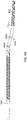
FIG. 5D is a flattened view of the curved portion ofFIG. 5A . -
FIG. 6A shows an atherectomy catheter including an embodiment of a user-activated curved portion. -
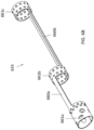
FIG. 6B shows the frame of the curved portion ofFIG. 6A including annular and longitudinal spines. -
FIG. 6C shows a side view of the spine ofFIG. 6B . -
FIG. 6D shows a cross-sectional view of the spine ofFIG. 6B . -
FIG. 6E is a flattened view of the spine ofFIG. 6B . -
FIG. 7A shows a portion of an atherectomy catheter including a fixed jog section and a flexible section. -
FIG. 7B shows a flattened view of the curved portion of the catheter ofFIG. 7A . -
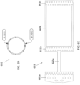
FIG. 8A shows an exemplary flexible nosecone for use with an atherectomy catheter. -
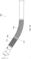
FIG. 8B shows a flattened view of a portion of the nosecone ofFIG. 8A . - Described herein is an atherectomy catheter having an elongate body with a curved distal portion, a nosecone and a rotatable annular cutter. The curved portion (which can otherwise be called a bent/bendable portion or jog mechanism) can advantageously be used to push the cutter up against the vessel wall to enhance the efficiency of cutting.
-
FIGS. 1A and1B show anexemplary atherectomy catheter 100 having a curved portion along the elongate catheter body. Referring toFIGS. 1A-2 , theatherectomy catheter 100 can include acatheter body 101 with acurved portion 133, a rotatableannular cutter 103 at a distal end of thecatheter body 101, and anosecone 105 at a distal end of thecatheter body 101. Thenosecone 105 can include a cuttingwindow 107 configured to allow thecutter 103 to cut therethrough. Thecatheter 101 can further include acurved portion 133 in thecatheter body 101 to radially push thecutter 103 against the vessel wall. - The
curved portion 133 can be a fixed jog (i.e., have a pre-set shape). Further, the curved portion can be curved or bent such that the cuttingwindow 107 is on the radially outermost portion of the curved portion 133 (thereby allowing the cuttingwindow 107 to be urged against a vessel wall in use). Thecurved portion 133 can be pre-formed, for example, by using pre-deflected shaped-set nitinol ribbon segments embedded in the outer shaft. Thecurved portion 133 can have twoinflection points catheter body 101 is offset from, but substantially parallel to, a proximal end of thecatheter body 101. Alternatively, the distal end and proximal ends of thecatheter body 101 can be at a slight angle to one another so as to control the angle of cutter engagement with the vessel wall. - Thus, as shown in
FIG. 2 , the "s-shape" of thecurved portion 133 can include aproximal section 137 have a length b that extends from the center of thedistal inflection point 155 to the center of theproximal inflection point 166. Further, thecurved portion 133 can include adistal section 135 having a length a that extends from thecutting edge 112 to the center of thedistal inflection point 155. Further, there can bedistal angle 1 at the distal end of the "s-shape" and aproximal angle 2 at the proximal end of the "s-shape." These lengths (a, b) and angles (1, 2) can be tuned to achieve the desired jog or offset in order to obtain optimum apposition to tissue walls. For example, the length a can be shorter than the length b to ensure that the cutter is as close to theangle 1 as possible, thereby providing better apposition of the cutter 303. Theangles angle 1 is 140 degrees andangle 2 is 160 degrees for a catheter configured to be used in a vessel having a 2.5-4mm diameter. - The
curved portion 133 can advantageously radially push the distal end of the catheter against avessel wall 200, thereby enabling optimized cutting and/or imaging of the vessel as shown inFIG. 1B . -
FIGS. 3A-3B show anotherexemplary catheter 300 that includes a curved portion 333 in the catheter body that urges the atherectomy cutter against the vessel wall. The curved portion 333 can have similar dimensions and features ascurved portion 133. In contrast to the fixed jogcurved portion 133 ofcatheter 100, however, the curved portion 333 can be a user-activated jog. Thus, referring toFIGS. 3A and3B , thecatheter 300, can be deflected into a curved portion 333 by tensile and compressive interaction between an inner shaft 313 (which can be a drive shaft for a cutter) andouter shaft 311 that are fixed together at the distal end but free to move relative to one another at the proximal end. Theouter shaft 311 can include stiffeningmembers 377a,b, such as nitinol or stainless steel, stiffening members, configured to bias the deflection to a set shape. As shown inFigure 3B , there can be two stiffeningmembers outer shaft 311 and axially and radially offset from one another. As a result, when compression is applied on the outer shaft 311 (such as by pulling on theinner shaft 313 or a separate pullwire or shaft), theportions 379a,b of the outer shaft opposite to thestiffening members 377a,b will contract. The contraction of the twoportions catheter 100 shown inFIG. 1 . As a result, the catheter will deflect into jog or s-shaped configuration where the distal end of the shaft is offset and parallel to the main shaft body. It is to be understood that other numbers and arrangements of stiffening members are possible, as are other resulting jog shapes. - Another
atherectomy catheter 400 including a user-activatedcurved portion 433 is shown inFIGS. 4A-4B . Theatherectomy catheter 400 includes anelongate body 401, anosecone 405 attached thereto, and a cuttingwindow 407 configured to expose anannular cutter 411 therethrough. Moreover, thecatheter 400 includes acurved portion 433. Thecurved portion 433 includescurved sections catheter body 401 and/or thenosecone 405 is offset from, but substantially parallel to, a proximal end of thecatheter body 401. Alternatively, the distal end of theelongate body 401 and/or thenosecone 405 forms an angle relative to a proximal end of thecatheter body 401. - Thus, as shown in
FIG. 4B , the "s-shape" of thejog 433 can have a proximalcurved section 426 and a distalcurved section 425 having a length c. Further, there can bedistal angle 1 at the distal end of the "s-shape" and aproximal angle 2 at the proximal end of the "s-shape." The lengths (c, d) and angles (1, 2) of thejog 433 can be tuned to achieve the desired jog or offset in order to obtain optimum apposition to tissue walls. For example, theangles proximal section 426 is greater than the length c of thedistal section 425. In one example, the length c is 5mm, the length d is 8mm, and theangles curved portion 433 can be a configured to adopt the s-shape during use of the catheter, as described above with respect to curved portion 333. - An exemplary user-activated curved portion 533 (e.g., for use as curved portion 433) is shown in
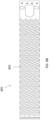
FIGS. 5A-5D . Thecurved portion 533 can include a frame (e.g., made of Nitinol or stainless steel) including a series of circumferential slits 550 (e.g., laser cuts) that are patterned along the circumference of theelongate body 501 within thecurved sections curved sections longitudinal spine 560a,b extending therethrough. Thelongitudinal spines 560a,b can be positioned approximately 180 degrees away from one another (i.e., on opposites sides of the elongate body 501) and extend substantially parallel to the longitudinal central axis of theelongate body 501. The frame can further include acircumferential spine 561 separating the twocurved sections spine 560a,b and 561 is formed of a substantially solid piece of material that does not include slits therein. In use, as thecircumferential slits 550 compress and/or overlap with one another during bending, thelongitudinal spines 560a,b form the backbone of thecurved sections - Referring to
FIG. 5D , theslits 550 can be arranged in a pattern that is configured to provide flexibility while maintaining structural integrity of the elongate body. Thus, the majority of theslits 550 can have the same length, but be offset from one another. For example, the slits indistal section 525 can be arranged in rows (1,2) and columns (A, B). Each slit 550 (except the shorter slits bordering thespine 560a) can have a length equivalent to the width of columns A + B + A. Further, the slits can be offset from one another by a distance of A + B. Thus, each column A can include slits from everyrow row 1 or 2). Column B thus provides structural integrity to the slitted portion of the device. The slits insection 526 can be similarly arranged, but can be offset such that each column C (with slits from every row 3,4) is aligned with the central axis of each column D (with slits from row 3 or 4). The offset helps provide stability to the catheter as it bends. - In some examples, pushing or pulling on a shaft of the catheter, such as the cutter drive shaft, a pullshaft, or a pullwire can activate the
curved portion 533. That is, as the shaft is pulled back proximally, it can place compression on the outerelongate body 501, causing theslits 550 to compress and/or move over one another while thespines 560a,b maintain their length. The resulting s-shape (seeFigure 4B ) allows the cutter (just distal to spine 460a) to be pushed up against the vessel wall. - The
slits 550 shown inFIGS. 5A-5D are of a repeated, symmetrical pattern. However, the pattern need not be symmetrical. The slits can all have the same length. Alternatively, some of the slits are longer than others. In one example, the slits are 0.041 mm (.0016") wide and 1.46 mm (.0575") long with a 0.089 mm (.0035") offset from the next row of slits. - Areas of the catheter body having a greater degree of slits will be more flexible than those having lesser degrees of slits. In one example, the slits can extend all the way through the elongate catheter. In other instances, some of the slits may be deeper or shallower than others which also affects the flexibility of the corresponding region. In some variations of the curved portion, a range of deflection between the flexible segments may be achieved. This may be accomplished through different geometric patterns of slits, different spacing of the slits, frequency of the slits, size of the slits, and so forth. In some instances, the degree of stiffness may be adjusted by adding additional spines of various lengths in certain areas or adjusting the width of the spines.
- Referring to
FIGS. 6A-6E , a curved portion 633 (e.g., for use as curved portion 433) according to the invention is shown. Thecurved portion 633 includes a frame having threeannular ring spines 661a,b,c connected together by twolongitudinal spines 660a,b. Thelongitudinal spines 660a,b are approximately 180° away from one another. The distalannular ring spine 661a is beveled at the distal end, as shown inFIG. 6C , to allow for dropping or pivoting of thenosecone 605. Further, the space between theannular ring spines 661a,b,c and thelongitudinal spines 660a,b is open or cut-away (i.e., not include the frame material). In some embodiments, the frame can be laminated to theelongate body 601 with one or more thin polymer layers, such as Tecothane. Theannular ring spines 661a,b,c can include holes therein for soldering or laminating the mechanism to the elongate body of the catheter. In other embodiments, the frame can remain unlaminated to provide for greater flexibility. When compression is placed upon the mechanism, the mechanism can bend away from each of the spines, forming an s-shape. - Referring to
FIGS. 7A and7B , anatherectomy catheter 700 can include acurved portion 777 that includes a fixedjog section 707 and aflexible section 717. The fixedjog section 707 can either be proximal to the flexible section 717 (as shown) or distal to theflexible section 717. In some examples, the fixedjog section 707 is longer than theflexible section 717. For example, the fixedjog section 707 can be 5-10mm, such as 8mm, and theflexible section 717 can be 2-6mm, such as 5mm. Further, (as shown), the fixedjog section 707 can include only a single curve rather than a double curve (e.g., forming a c-shape rather than an s-shape). The angle of the curve can be, for example, 120° to 175°, such as 130° to 160°, such as approximately 145°. Theflexible section 717 can be configured to bend passively during use (i.e., when acted upon by the vessel wall), for example to form an angle of between 90° and 180°, such as 110-170°, such as 130°-160°. - The
curved portion 777 can be made of a laminated frame. Referring toFIG. 7B , thecurved portion 777 can include a frame that includes a plurality ofcircumferential slits 750a,b extending therethrough. Theslits 750a of theflexible section 717 can extend entirely around the circumference (i.e., include no longitudinal spine therein) while theslits 750b of the fixedjog section 707 can end at a longitudinal spine 760 extending through the fixedjog section 707. Anannular spine 761 can separate theflexible section 717 and the fixedjog section 707. The frame can be made, for example, of Nitinol or stainless steel. Further, the frame can be laminated with a thin layer of polymer, such as Tecothane, on one or both sides. In some examples, only the fixedjog section 707 is laminated while theflexible section 717 remains unlaminated. - Referring to
FIG. 7B , theslits 750a,b can be arranged in a pattern that is configured to provide flexibility in theflexible section 717 while maintaining structural integrity of the elongate body in both theflexible section 717 and the fixedjog section 707. Thus, the majority of theslits 750a,b can have the same length, but be offset from one another. For example, theslits 750a in theflexible section 717 can be arranged in rows (1,2) and columns (A, B). Eachslit 750a can have a length equivalent to the width of columns A + B + A. Further, the slits can be offset from one another by a distance of A + B. Thus, each column A can include slits from everyrow row 1 or 2). Column B thus provides structural integrity to the slitted portion of the device. Theslits 750a of theflexible section 717 can provide flexibility to allow thecatheter 700 to achieve the desired curvature in any direction when inside the body (i.e., the slits can pull apart on the outside of the curve and compress and/or overlap when on the inside of the curve). For example, theflexible section 717 can bend to align the cutter with the edge of the vessel. - Further, the
slits 750b in fixed jog section 707 (except the shorter slits bordering thespine 560a) can likewise have a length equivalent to the width of columns A + B + A. Further, the slits can be offset from one another by a distance of A + B. Thus, each column A can include slits from everyrow row 1 or 2). Infixed jog section 707, however, the spine 760 can be heat-set to set the angle of the jog, fixing the jog. - Referring to
FIG. 8A , in some examples, thenosecone 805 can be flexible. That is, the elongate body can include one or more curves (as described herein), and thenosecone 805 can provide additional flexibility to allow the catheter to take the desired shape. Thenosecone 805 can, for example, include a repeating laser cut pattern covered in a laminate layer. As shown inFIG. 8A , the pattern can include a series ofspiral slits 850 extending around the circumference of the nosecone. Some examples, the laser cut pattern can be cut out of stainless steel, which can be laminated with a polymer, such as Tecothane. Additional flexible nosecone designs are described inU.S. Patent Application No. 14/776,749, filed September 15, 2015 U.S. Patent Application Publication No. 2016-0008025-A1 and International Patent Application No.PCT/US2017/035510, filed June 1, 2017 and titled "CATHETER DEVICE WITH DETACHABLE DISTAL END. - In some embodiments, the curved portions of the elongate catheter bodies described herein can form a substantially s-shape with two different inflection points of opposite curvatures. One or more of the curves can be fixed. Alternatively, one or more of the curves can be user activated, e.g., by pulling on the driveshaft or a separate pullshaft or wire. Further, any of the designs described herein can include a flexible section (e.g., of the elongate body or the nosecone) that allows the catheter to take the desired curvature during use.
- In some examples, the amount of curvature of the user-adjusted curved portions can be further adjusted either prior to or during an atherectomy procedure based on the curvatures of the artery and the location of the plaque formation. For example, by tensioning a shaft of the catheter, the curved portion can constrict and adopt a sharper angle. Alternatively, when the shaft is relaxed, the curved portion can relax and adopt a wider angle. In such examples, the angles of deflection may be adjusted, for example, by 5 to 20 degrees.
- In some examples, the user-adjusted curved portions can have a pre-shaped bend or curvature that can be further adjusted prior to or during an atherectomy procedure. In other embodiments, the curved portions can be straight before the user-activated bend is activated.
- In any of the examples described herein, the nosecone can be configured to hold tissue that is debulked by the cutter. Further, the driveshaft and cutter can be configured to move distally to pack tissue into the nosecone.
- Lamination of a framework can cause the laminating material to heat and shrink, pushing into open slits and fixing the shape of the frame (e.g., in a pre-shaped jog). For example, the
curved portions 533 and/or 633 can be laminated so as to create a fixed jog that can either be further adjusted by pulling on the driveshaft or that remains fixed throughout the procedure. Alternatively, lamination of the framework can keep the slits open and free of material, allowing for greater flexibility. - Any of the curved portions described herein may be used alone or in combination with a mechanism to deflect the nosecone. In some examples, the nosecone can be deflected by pulling on a cutter driveshaft. Such deflection mechanisms are described in
U.S. Patent Application No. 15/072,272, filed March 16, 2016 , titled "ATHERECTOMY CATHETERS DEVICES HAVING MULTI-CHANNEL BUSHINGS," nowU.S. Patent No. 9,592,075 U.S. Patent Application No. 15/076,568 filed March 21, 2016 , titled "ATHERECTOMY CATHETERS AND OCCLUSION CROSSING DEVICES," nowU.S. Patent No. 9/498,247 - In examples where the nosecone is not deflected, the respective cutting windows can be optimized so as to allow for automatic invagination of tissue into the cutting window. Further, having the nosecone not deflect and relying entirely on the curved portion for tissue apposition can advantageously prevent the cutter from escaping from the nosecone during packing. Further, having the curved portion alone (i.e., without the nosecone activation) can advantageously eliminate having to use additional mechanisms to force a jog mid-surgery, such as pulling or pushing on a shaft, thereby enhancing both ease of use and enhancing image stability.
- The atherectomy catheters having a curved portion described herein advantageously allows easier and closer positioning of the atherectomy cutter to plaque close to the inner artery walls. That is, the curved portions can be configured such that the exposed portion of the cutter (e.g., the area extending through the cutter window) moves closer to the vessel wall than the unexposed side of the cutter. This positioning can make cutting during the atherectomy procedure more efficient.
- When a feature or element is herein referred to as being "on" another feature or element, it can be directly on the other feature or element or intervening features and/or elements may also be present. In contrast, when a feature or element is referred to as being "directly on" another feature or element, there are no intervening features or elements present. It will also be understood that, when a feature or element is referred to as being "connected", "attached" or "coupled" to another feature or element, it can be directly connected, attached or coupled to the other feature or element or intervening features or elements may be present. In contrast, when a feature or element is referred to as being "directly connected", "directly attached" or "directly coupled" to another feature or element, there are no intervening features or elements present. Although described or shown with respect to one embodiment, the features and elements so described or shown can apply to other embodiments. It will also be appreciated by those of skill in the art that references to a structure or feature that is disposed "adjacent" another feature may have portions that overlap or underlie the adjacent feature.
- Terminology used herein is for the purpose of describing particular embodiments only and is not intended to be limiting of the invention. For example, as used herein, the singular forms "a", "an" and "the" are intended to include the plural forms as well, unless the context clearly indicates otherwise. It will be further understood that the terms "comprises" and/or "comprising," when used in this specification, specify the presence of stated features, steps, operations, elements, and/or components, but do not preclude the presence or addition of one or more other features, steps, operations, elements, components, and/or groups thereof. As used herein, the term "and/or" includes any and all combinations of one or more of the associated listed items and may be abbreviated as "/".
- Spatially relative terms, such as "under", "below", "lower", "over", "upper" and the like, may be used herein for ease of description to describe one element or feature's relationship to another element(s) or feature(s) as illustrated in the figures. It will be understood that the spatially relative terms are intended to encompass different orientations of the device in use or operation in addition to the orientation depicted in the figures. For example, if a device in the figures is inverted, elements described as "under" or "beneath" other elements or features would then be oriented "over" the other elements or features. Thus, the exemplary term "under" can encompass both an orientation of over and under. The device may be otherwise oriented (rotated 90 degrees or at other orientations) and the spatially relative descriptors used herein interpreted accordingly. Similarly, the terms "upwardly", "downwardly", "vertical", "horizontal" and the like are used herein for the purpose of explanation only unless specifically indicated otherwise.
- Although the terms "first" and "second" may be used herein to describe various features/elements (including steps), these features/elements should not be limited by these terms, unless the context indicates otherwise. These terms may be used to distinguish one feature/element from another feature/element. Thus, a first feature/element discussed below could be termed a second feature/element, and similarly, a second feature/element discussed below could be termed a first feature/element without departing from the teachings of the present invention.
- Throughout this specification and the claims which follow, unless the context requires otherwise, the word "comprise", and variations such as "comprises" and "comprising" means various components can be co-jointly employed in the articles (e.g., compositions and apparatuses including devices). For example, the term "comprising" will be understood to imply the inclusion of any stated elements or steps but not the exclusion of any other elements or steps.
- As used herein in the specification and claims, including as used in the examples and unless otherwise expressly specified, all numbers may be read as if prefaced by the word "about" or "approximately," even if the term does not expressly appear. The phrase "about" or "approximately" may be used when describing magnitude and/or position to indicate that the value and/or position described is within a reasonable expected range of values and/or positions. For example, a numeric value may have a value that is +/- 0.1% of the stated value (or range of values), +/- 1% of the stated value (or range of values), +/- 2% of the stated value (or range of values), +/- 5% of the stated value (or range of values), +/- 10% of the stated value (or range of values), etc. Any numerical range recited herein is intended to include all sub-ranges subsumed therein.
- Optional features of various device and system embodiments may be included in some embodiments and not in others. Therefore, the foregoing description is provided primarily for exemplary purposes and should not be interpreted to limit the scope of the invention as it is set forth in the claims. The invention is defined solely by the claims.
- The examples and illustrations included herein show, by way of illustration and not of limitation, specific embodiments in which the subject matter may be practiced.
Claims (9)
- An atherectomy catheter for use in a vessel comprising:an elongate catheter body (601);an annular cutter;an s-shaped curved portion (633) in the elongate catheter body; anda nosecone (605) configured to pivot away from the elongate body (601) to expose the cutter,characterized in that:(i) the curved portion includes a frame having a longitudinal proximal spine (660b) connecting a first annular spine (661c) to a second annular spine (661b), and a longitudinal distal spine (660a) connecting the second annular spine (661b) to a third annular spine (661a), the longitudinal proximal spine (660b) positioned approximately 180 degrees away from the longitudinal distal spine (660a),(ii) the frame has space that is open on a side opposite the longitudinal proximal spine (660b) between the first annular spine (661c) and the second annular spine (661b), and the frame has space that is open on a side opposite the longitudinal distal spine (660a) between the second annular spine (661b) and the third annular spine (661a),(iii) the third annular spine (661a) is a distal-most spine and includes a beveled distal edge, and(iv) the bevel is configured to provide space for the nosecone to pivot.
- The atherectomy catheter of claim 1, further comprising a cutting window through which the annular cutter extends, the cutting window positioned distal of the curved portion and on an outer circumference of the s-shaped curve (633) so as to urge the cutter into the vessel.
- The atherectomy catheter of claim 1, wherein the s-shaped curved portion (633) is configured to be activated by pulling or pushing on a shaft of the atherectomy catheter.
- The atherectomy catheter of claim 1, further comprising at least one laminating layer positioned over or under the frame.
- The atherectomy catheter of claim 4, wherein the laminating layer is made of a polymer.
- The atherectomy catheter of claim 1, wherein the frame is made of metal.
- The atherectomy catheter of claim 1, wherein the longitudinal proximal spine (660b) forms a first angle, and wherein the longitudinal distal spine (660a) forms a second angle, the first and second angles extending in opposite directions, and wherein the first angle is between 140 and 160 degrees and the second angle is between 140 and 160 degrees.
- The atherectomy catheter of claim 1, wherein the curved portion (633) is laminated.
- The atherectomy catheter of claim 1, wherein the s-shaped curved portion (633) includes a first inflection point between the first annular spine (661c) and the second annular spine (661b), and a second inflection point between the second annular spine (661b) and a third annular spine (661a).
Applications Claiming Priority (2)
| Application Number | Priority Date | Filing Date | Title |
|---|---|---|---|
| US201662357173P | 2016-06-30 | 2016-06-30 | |
| PCT/US2017/040431 WO2018006041A1 (en) | 2016-06-30 | 2017-06-30 | Atherectomy catheter with shapeable distal tip |
Publications (3)
| Publication Number | Publication Date |
|---|---|
| EP3478190A1 EP3478190A1 (en) | 2019-05-08 |
| EP3478190A4 EP3478190A4 (en) | 2020-01-22 |
| EP3478190B1 true EP3478190B1 (en) | 2023-03-15 |
Family
ID=60787616
Family Applications (1)
| Application Number | Title | Priority Date | Filing Date |
|---|---|---|---|
| EP17821409.4A Active EP3478190B1 (en) | 2016-06-30 | 2017-06-30 | Atherectomy catheter with shapeable distal tip |
Country Status (5)
| Country | Link |
|---|---|
| US (2) | US11224459B2 (en) |
| EP (1) | EP3478190B1 (en) |
| JP (1) | JP7061080B2 (en) |
| CN (1) | CN109414273B (en) |
| WO (1) | WO2018006041A1 (en) |
Families Citing this family (31)
| Publication number | Priority date | Publication date | Assignee | Title |
|---|---|---|---|---|
| US9498600B2 (en) | 2009-07-01 | 2016-11-22 | Avinger, Inc. | Atherectomy catheter with laterally-displaceable tip |
| AU2010253912B2 (en) | 2009-05-28 | 2015-03-05 | Avinger, Inc. | Optical Coherence Tomography for biological imaging |
| US11382653B2 (en) | 2010-07-01 | 2022-07-12 | Avinger, Inc. | Atherectomy catheter |
| JP6205344B2 (en) | 2011-03-28 | 2017-09-27 | アビンガー・インコーポレイテッドAvinger, Inc. | Occlusion crossing device, imaging device and atherectomy device |
| US9345406B2 (en) | 2011-11-11 | 2016-05-24 | Avinger, Inc. | Occlusion-crossing devices, atherectomy devices, and imaging |
| WO2013172972A1 (en) | 2012-05-14 | 2013-11-21 | Avinger, Inc. | Optical coherence tomography with graded index fiber for biological imaging |
| US11284916B2 (en) | 2012-09-06 | 2022-03-29 | Avinger, Inc. | Atherectomy catheters and occlusion crossing devices |
| JP6291025B2 (en) | 2013-03-15 | 2018-03-14 | アビンガー・インコーポレイテッドAvinger, Inc. | Optical pressure sensor assembly |
| US9854979B2 (en) | 2013-03-15 | 2018-01-02 | Avinger, Inc. | Chronic total occlusion crossing devices with imaging |
| EP3019096B1 (en) | 2013-07-08 | 2023-07-05 | Avinger, Inc. | System for identification of elastic lamina to guide interventional therapy |
| US10285720B2 (en) | 2014-03-11 | 2019-05-14 | Neuravi Limited | Clot retrieval system for removing occlusive clot from a blood vessel |
| EP3154452A1 (en) | 2014-06-13 | 2017-04-19 | Neuravi Limited | Devices for removal of acute blockages from blood vessels |
| US10265086B2 (en) | 2014-06-30 | 2019-04-23 | Neuravi Limited | System for removing a clot from a blood vessel |
| WO2016007652A1 (en) | 2014-07-08 | 2016-01-14 | Avinger, Inc. | High speed chronic total occlusion crossing devices |
| US10568520B2 (en) | 2015-07-13 | 2020-02-25 | Avinger, Inc. | Micro-molded anamorphic reflector lens for image guided therapeutic/diagnostic catheters |
| JP6959255B2 (en) | 2016-04-01 | 2021-11-02 | アビンガー・インコーポレイテッドAvinger, Inc. | Catheter device for porridge resection |
| MX2019001899A (en) | 2016-08-17 | 2019-09-18 | Neuravi Ltd | A clot retrieval system for removing occlusive clot from a blood vessel. |
| JP2020142074A (en) | 2019-03-04 | 2020-09-10 | ニューラヴィ・リミテッド | Actuated clot retrieval catheter |
| EP3791815A1 (en) | 2019-09-11 | 2021-03-17 | Neuravi Limited | Expandable mouth catheter |
| US11478609B2 (en) * | 2019-09-26 | 2022-10-25 | Biosense Webster (Israel) Ltd. | Bendable guidewire |
| US11793400B2 (en) | 2019-10-18 | 2023-10-24 | Avinger, Inc. | Occlusion-crossing devices |
| EP4044943A4 (en) * | 2019-10-18 | 2024-02-14 | Avinger Inc | Atherectomy catheter with shapeable distal tip |
| US11839725B2 (en) | 2019-11-27 | 2023-12-12 | Neuravi Limited | Clot retrieval device with outer sheath and inner catheter |
| US11779364B2 (en) | 2019-11-27 | 2023-10-10 | Neuravi Limited | Actuated expandable mouth thrombectomy catheter |
| CN113116498B (en) * | 2019-12-31 | 2022-07-05 | 先健科技(深圳)有限公司 | Ostomy appliance and ostomy system |
| US11633198B2 (en) | 2020-03-05 | 2023-04-25 | Neuravi Limited | Catheter proximal joint |
| US11944327B2 (en) | 2020-03-05 | 2024-04-02 | Neuravi Limited | Expandable mouth aspirating clot retrieval catheter |
| US11883043B2 (en) | 2020-03-31 | 2024-01-30 | DePuy Synthes Products, Inc. | Catheter funnel extension |
| US11759217B2 (en) | 2020-04-07 | 2023-09-19 | Neuravi Limited | Catheter tubular support |
| US11872354B2 (en) | 2021-02-24 | 2024-01-16 | Neuravi Limited | Flexible catheter shaft frame with seam |
| US11937839B2 (en) | 2021-09-28 | 2024-03-26 | Neuravi Limited | Catheter with electrically actuated expandable mouth |
Family Cites Families (554)
| Publication number | Priority date | Publication date | Assignee | Title |
|---|---|---|---|---|
| US3367727A (en) | 1965-10-22 | 1968-02-06 | Abraham W. Ward | Oral surgery tool with interchangeable blades |
| US3908637A (en) | 1974-04-22 | 1975-09-30 | Louis W Doroshow | Rigid urethral instrument |
| GB1531659A (en) | 1977-07-21 | 1978-11-08 | Gekhman B | Apparatus for disintegration of urinary concretions |
| US4527553A (en) | 1980-04-28 | 1985-07-09 | Upsher Michael S | Laryngoscope with improved light source |
| US4578061A (en) | 1980-10-28 | 1986-03-25 | Lemelson Jerome H | Injection catheter and method |
| US5435805A (en) | 1992-08-12 | 1995-07-25 | Vidamed, Inc. | Medical probe device with optical viewing capability |
| US4621353A (en) | 1982-09-09 | 1986-11-04 | Burroughs Corporation | Optical memory system providing improved focusing control and improved beam combining and separating apparatus |
| US4487206A (en) | 1982-10-13 | 1984-12-11 | Honeywell Inc. | Fiber optic pressure sensor with temperature compensation and reference |
| FR2541784B1 (en) | 1983-02-25 | 1986-05-16 | Thomson Csf | DEVICE FOR STATIC DEFLECTION OF AN INFRARED BEAM |
| US4611600A (en) | 1983-11-21 | 1986-09-16 | Cordis Corporation | Optical fiber pressure transducer |
| US5178153A (en) | 1984-03-08 | 1993-01-12 | Einzig Robert E | Fluid flow sensing apparatus for in vivo and industrial applications employing novel differential optical fiber pressure sensors |
| US5041082A (en) | 1986-06-16 | 1991-08-20 | Samuel Shiber | Mechanical atherectomy system and method |
| US4926858A (en) | 1984-05-30 | 1990-05-22 | Devices For Vascular Intervention, Inc. | Atherectomy device for severe occlusions |
| US4552554A (en) | 1984-06-25 | 1985-11-12 | Medi-Tech Incorporated | Introducing catheter |
| US4651753A (en) | 1984-10-12 | 1987-03-24 | Jayco Pharmaceuticals | Endoscopic multiple biopsy instrument |
| US4686982A (en) | 1985-06-19 | 1987-08-18 | John Nash | Spiral wire bearing for rotating wire drive catheter |
| US4681106A (en) | 1985-08-12 | 1987-07-21 | Intravascular Surgical Instruments, Inc. | Catheter based surgical methods and apparatus therefor |
| US4654024A (en) | 1985-09-04 | 1987-03-31 | C.R. Bard, Inc. | Thermorecanalization catheter and method for use |
| US5182291A (en) | 1986-02-14 | 1993-01-26 | Sanofi | Pyrozala-pyridyl aminoabkoxyphenol compounds |
| US5000185A (en) | 1986-02-28 | 1991-03-19 | Cardiovascular Imaging Systems, Inc. | Method for intravascular two-dimensional ultrasonography and recanalization |
| US4771774A (en) | 1986-02-28 | 1988-09-20 | Devices For Vascular Intervention, Inc. | Motor drive unit |
| US4691708A (en) | 1986-03-10 | 1987-09-08 | Cordis Corporation | Optical pressure sensor for measuring blood pressure |
| JPH0732758B2 (en) | 1986-05-21 | 1995-04-12 | オリンパス光学工業株式会社 | Endoscope |
| US4729763A (en) | 1986-06-06 | 1988-03-08 | Henrie Rodney A | Catheter for removing occlusive material |
| SE453561B (en) | 1986-06-25 | 1988-02-15 | Radisensor Ab | MINIATURIZED SENSOR FOR PHYSIOLOGICAL PRESSURE SEATS |
| US4841977A (en) | 1987-05-26 | 1989-06-27 | Inter Therapy, Inc. | Ultra-thin acoustic transducer and balloon catheter using same in imaging array subassembly |
| US4857046A (en) | 1987-10-21 | 1989-08-15 | Cordis Corporation | Drive catheter having helical pump drive shaft |
| US5047040A (en) | 1987-11-05 | 1991-09-10 | Devices For Vascular Intervention, Inc. | Atherectomy device and method |
| US4920961A (en) | 1988-06-02 | 1990-05-01 | Circon Corporation | System for disconnetably mounting an endoscope sheath with an endoscope tool |
| EP0347098B1 (en) | 1988-06-13 | 1996-02-28 | Samuel Shiber | Atherectomy system with a guide-wire |
| SE460396B (en) | 1988-07-29 | 1989-10-09 | Radisensor Ab | MINIATURIZED SENSOR DEVICE FOR SEATING PHYSIOLOGICAL PRESSURE IN VIVO |
| US5099850A (en) | 1989-01-17 | 1992-03-31 | Olympus Optical Co., Ltd. | Ultrasonic diagnostic apparatus |
| US5431673A (en) | 1989-02-17 | 1995-07-11 | American Biomed, Inc. | Distal atherectomy catheter |
| US5226909A (en) | 1989-09-12 | 1993-07-13 | Devices For Vascular Intervention, Inc. | Atherectomy device having helical blade and blade guide |
| US5085662A (en) | 1989-11-13 | 1992-02-04 | Scimed Life Systems, Inc. | Atherectomy catheter and related components |
| US5054501A (en) | 1990-05-16 | 1991-10-08 | Brigham & Women's Hospital | Steerable guide wire for cannulation of tubular or vascular organs |
| US5674232A (en) | 1990-06-05 | 1997-10-07 | Halliburton; Alexander George | Catheter and method of use thereof |
| BE1003189A5 (en) | 1990-07-27 | 1992-01-07 | B A Cosurvey Optics S P R L B | PRESSURE SENSOR. |
| JP3467268B2 (en) | 1990-08-06 | 2003-11-17 | アキュレイズ,インコーポレイテッド | Fiber optic laser catheter |
| US5142155A (en) | 1991-03-11 | 1992-08-25 | Hewlett-Packard Company | Catheter tip fluorescence-quenching fiber optic pressure sensor |
| US5465147A (en) | 1991-04-29 | 1995-11-07 | Massachusetts Institute Of Technology | Method and apparatus for acquiring images using a ccd detector array and no transverse scanner |
| US6134003A (en) | 1991-04-29 | 2000-10-17 | Massachusetts Institute Of Technology | Method and apparatus for performing optical measurements using a fiber optic imaging guidewire, catheter or endoscope |
| WO1992019930A1 (en) | 1991-04-29 | 1992-11-12 | Massachusetts Institute Of Technology | Method and apparatus for optical imaging and measurement |
| US6564087B1 (en) | 1991-04-29 | 2003-05-13 | Massachusetts Institute Of Technology | Fiber optic needle probes for optical coherence tomography imaging |
| US6501551B1 (en) | 1991-04-29 | 2002-12-31 | Massachusetts Institute Of Technology | Fiber optic imaging endoscope interferometer with at least one faraday rotator |
| US5956355A (en) | 1991-04-29 | 1999-09-21 | Massachusetts Institute Of Technology | Method and apparatus for performing optical measurements using a rapidly frequency-tuned laser |
| US6485413B1 (en) | 1991-04-29 | 2002-11-26 | The General Hospital Corporation | Methods and apparatus for forward-directed optical scanning instruments |
| US7074231B2 (en) | 1991-06-13 | 2006-07-11 | Advanced Cardiovascular Systems, Inc. | Convertible mode vascular catheter system |
| US5190050A (en) | 1991-11-08 | 1993-03-02 | Electro-Catheter Corporation | Tip deflectable steerable catheter |
| ATE150953T1 (en) | 1992-01-13 | 1997-04-15 | Schneider Usa Inc | SURGICAL CUTTING INSTRUMENT |
| US5192291A (en) | 1992-01-13 | 1993-03-09 | Interventional Technologies, Inc. | Rotationally expandable atherectomy cutter assembly |
| GB9207532D0 (en) | 1992-04-07 | 1992-05-20 | Innovata Biomed Ltd | Medical connection system |
| JPH0627343A (en) | 1992-07-06 | 1994-02-04 | Nippon Telegr & Teleph Corp <Ntt> | Optical fiber juncture for optical fiber amplifier |
| US5312415A (en) | 1992-09-22 | 1994-05-17 | Target Therapeutics, Inc. | Assembly for placement of embolic coils using frictional placement |
| US5383460A (en) | 1992-10-05 | 1995-01-24 | Cardiovascular Imaging Systems, Inc. | Method and apparatus for ultrasound imaging and atherectomy |
| US5333142A (en) | 1992-10-26 | 1994-07-26 | The United States Of America As Represented By The Secretary Of The Navy | Technique for intracavity sum frequency generation |
| US5643297A (en) | 1992-11-09 | 1997-07-01 | Endovascular Instruments, Inc. | Intra-artery obstruction clearing apparatus and methods |
| US5383467A (en) | 1992-11-18 | 1995-01-24 | Spectrascience, Inc. | Guidewire catheter and apparatus for diagnostic imaging |
| US5460168A (en) | 1992-12-25 | 1995-10-24 | Olympus Optical Co., Ltd. | Endoscope cover assembly and cover-system endoscope |
| US5372601A (en) | 1993-03-30 | 1994-12-13 | Lary; Banning G. | Longitudinal reciprocating incisor |
| US5429136A (en) | 1993-04-21 | 1995-07-04 | Devices For Vascular Intervention, Inc. | Imaging atherectomy apparatus |
| JPH08509642A (en) | 1993-04-28 | 1996-10-15 | フォーカル,インコーポレイテッド | Device and method for intraluminal photothermoforming |
| US5868778A (en) | 1995-10-27 | 1999-02-09 | Vascular Solutions, Inc. | Vascular sealing apparatus and method |
| US6017359A (en) | 1993-05-25 | 2000-01-25 | Vascular Solutions, Inc. | Vascular sealing apparatus |
| US5383896A (en) | 1993-05-25 | 1995-01-24 | Gershony; Gary | Vascular sealing device |
| US5951583A (en) | 1993-05-25 | 1999-09-14 | Vascular Solutions, Inc. | Thrombin and collagen procoagulant and process for making the same |
| US5579767A (en) | 1993-06-07 | 1996-12-03 | Prince; Martin R. | Method for imaging abdominal aorta and aortic aneurysms |
| US5366464A (en) | 1993-07-22 | 1994-11-22 | Belknap John C | Atherectomy catheter device |
| CH687228A5 (en) | 1993-09-15 | 1996-10-31 | Synthes Ag | Drill head. |
| DE69433410T2 (en) | 1993-10-07 | 2004-10-07 | Boston Scient Corp | dilatation catheter |
| US5507760A (en) | 1993-11-09 | 1996-04-16 | Devices For Vascular Intervention, Inc. | Cutter device |
| JPH07184888A (en) | 1993-12-27 | 1995-07-25 | Toshiba Corp | Ultrasonic diagnostic system |
| US5437284A (en) | 1993-12-30 | 1995-08-01 | Camino Laboratories, Inc. | System and method for in vivo calibration of a sensor |
| US5517998A (en) | 1994-01-24 | 1996-05-21 | Medamicus, Inc. | Closed loop pressure determination system and method for fiber optic pressure transducer system |
| JP2869020B2 (en) | 1994-03-23 | 1999-03-10 | 康男 橋本 | Cancer treatment device |
| DE69514262T2 (en) | 1994-03-23 | 2001-10-11 | Yasuo Hashimoto | Optical fiber catheter |
| US5507795A (en) | 1994-04-29 | 1996-04-16 | Devices For Vascular Intervention, Inc. | Catheter with perfusion system |
| US6032673A (en) | 1994-10-13 | 2000-03-07 | Femrx, Inc. | Methods and devices for tissue removal |
| US5836957A (en) | 1994-12-22 | 1998-11-17 | Devices For Vascular Intervention, Inc. | Large volume atherectomy device |
| US5632754A (en) | 1994-12-23 | 1997-05-27 | Devices For Vascular Intervention | Universal catheter with interchangeable work element |
| DE19504261A1 (en) | 1995-02-09 | 1996-09-12 | Krieg Gunther | Angioplasty catheter for dilating and / or opening blood vessels |
| US5681336A (en) | 1995-09-07 | 1997-10-28 | Boston Scientific Corporation | Therapeutic device for treating vien graft lesions |
| JP2000511786A (en) | 1995-09-20 | 2000-09-12 | テキサス・ハート・インスティチュート | Detection of temperature difference in pipe wall |
| US6615071B1 (en) | 1995-09-20 | 2003-09-02 | Board Of Regents, The University Of Texas System | Method and apparatus for detecting vulnerable atherosclerotic plaque |
| US6375615B1 (en) | 1995-10-13 | 2002-04-23 | Transvascular, Inc. | Tissue penetrating catheters having integral imaging transducers and their methods of use |
| US5556405A (en) | 1995-10-13 | 1996-09-17 | Interventional Technologies Inc. | Universal dilator with reciprocal incisor |
| RU2185859C2 (en) | 1995-10-20 | 2002-07-27 | Надим М. Закка | Device for removing stenoses and supporting vascular walls |
| US5907425A (en) | 1995-12-19 | 1999-05-25 | The Board Of Trustees Of The Leland Stanford Junior University | Miniature scanning confocal microscope |
| SE9601541D0 (en) | 1995-11-08 | 1996-04-23 | Pacesetter Ab | Guidewire assembly |
| US5843050A (en) | 1995-11-13 | 1998-12-01 | Micro Therapeutics, Inc. | Microcatheter |
| SE9504334D0 (en) | 1995-12-04 | 1995-12-04 | Pacesetter Ab | Guidewire assembly |
| US5733296A (en) | 1996-02-06 | 1998-03-31 | Devices For Vascular Intervention | Composite atherectomy cutter |
| NL1003172C2 (en) | 1996-05-20 | 1997-11-21 | Cordis Europ | Catheter insertion sheath with occlusion balloon. |
| EP0812568B1 (en) | 1996-06-11 | 2003-10-22 | Roke Manor Research Limited | Catheter tracking system |
| US5795295A (en) | 1996-06-25 | 1998-08-18 | Carl Zeiss, Inc. | OCT-assisted surgical microscope with multi-coordinate manipulator |
| US5779721A (en) | 1996-07-26 | 1998-07-14 | Kensey Nash Corporation | System and method of use for revascularizing stenotic bypass grafts and other blood vessels |
| US6080170A (en) | 1996-07-26 | 2000-06-27 | Kensey Nash Corporation | System and method of use for revascularizing stenotic bypass grafts and other occluded blood vessels |
| US6830577B2 (en) | 1996-07-26 | 2004-12-14 | Kensey Nash Corporation | System and method of use for treating occluded vessels and diseased tissue |
| US6929481B1 (en) | 1996-09-04 | 2005-08-16 | Immersion Medical, Inc. | Interface device and method for interfacing instruments to medical procedure simulation systems |
| US5830145A (en) | 1996-09-20 | 1998-11-03 | Cardiovascular Imaging Systems, Inc. | Enhanced accuracy of three-dimensional intraluminal ultrasound (ILUS) image reconstruction |
| US5904651A (en) | 1996-10-28 | 1999-05-18 | Ep Technologies, Inc. | Systems and methods for visualizing tissue during diagnostic or therapeutic procedures |
| US5722403A (en) | 1996-10-28 | 1998-03-03 | Ep Technologies, Inc. | Systems and methods using a porous electrode for ablating and visualizing interior tissue regions |
| US5872879A (en) | 1996-11-25 | 1999-02-16 | Boston Scientific Corporation | Rotatable connecting optical fibers |
| JPH10161018A (en) | 1996-11-27 | 1998-06-19 | Olympus Optical Co Ltd | Optical system |
| US5899915A (en) | 1996-12-02 | 1999-05-04 | Angiotrax, Inc. | Apparatus and method for intraoperatively performing surgery |
| US6010449A (en) | 1997-02-28 | 2000-01-04 | Lumend, Inc. | Intravascular catheter system for treating a vascular occlusion |
| US6508825B1 (en) | 1997-02-28 | 2003-01-21 | Lumend, Inc. | Apparatus for treating vascular occlusions |
| US6120516A (en) | 1997-02-28 | 2000-09-19 | Lumend, Inc. | Method for treating vascular occlusion |
| US5843103A (en) * | 1997-03-06 | 1998-12-01 | Scimed Life Systems, Inc. | Shaped wire rotational atherectomy device |
| US6183487B1 (en) | 1997-03-06 | 2001-02-06 | Scimed Life Systems, Inc. | Ablation device for reducing damage to vessels and/or in-vivo stents |
| US6758854B1 (en) | 1997-05-09 | 2004-07-06 | St. Jude Medical | Splittable occlusion balloon sheath and process of use |
| US5851212A (en) | 1997-06-11 | 1998-12-22 | Endius Incorporated | Surgical instrument |
| US6013072A (en) | 1997-07-09 | 2000-01-11 | Intraluminal Therapeutics, Inc. | Systems and methods for steering a catheter through body tissue |
| US6048349A (en) | 1997-07-09 | 2000-04-11 | Intraluminal Therapeutics, Inc. | Systems and methods for guiding a medical instrument through a body |
| US5987995A (en) | 1997-07-17 | 1999-11-23 | Sentec Corporation | Fiber optic pressure catheter |
| WO1999004700A1 (en) | 1997-07-24 | 1999-02-04 | Mcguckin James F Jr | Urinary catheter |
| GB9717580D0 (en) | 1997-08-19 | 1997-10-22 | Curry Paul | Device for opening blocked tubes |
| US6402719B1 (en) | 1997-09-05 | 2002-06-11 | Cordis Webster, Inc. | Steerable DMR catheter with infusion tube |
| EP0904797A3 (en) | 1997-09-24 | 2000-08-09 | ECLIPSE SURGICAL TECHNOLOGIES, Inc. | Steerable catheter with tip alignment and surface contact detector |
| US6193676B1 (en) | 1997-10-03 | 2001-02-27 | Intraluminal Therapeutics, Inc. | Guide wire assembly |
| US5951482A (en) | 1997-10-03 | 1999-09-14 | Intraluminal Therapeutics, Inc. | Assemblies and methods for advancing a guide wire through body tissue |
| WO1999023958A1 (en) | 1997-11-07 | 1999-05-20 | Prolifix Medical, Inc. | Methods and systems for treating obstructions in a body lumen |
| US6183432B1 (en) | 1997-11-13 | 2001-02-06 | Lumend, Inc. | Guidewire and catheter with rotating and reciprocating symmetrical or asymmetrical distal tip |
| US5938671A (en) | 1997-11-14 | 1999-08-17 | Reflow, Inc. | Recanalization apparatus and devices for use therein and method |
| US6110164A (en) | 1997-12-05 | 2000-08-29 | Intratherapeutics, Inc. | Guideless catheter segment |
| US6027514A (en) | 1997-12-17 | 2000-02-22 | Fox Hollow Technologies, Inc. | Apparatus and method for removing occluding material from body lumens |
| US6231546B1 (en) | 1998-01-13 | 2001-05-15 | Lumend, Inc. | Methods and apparatus for crossing total occlusions in blood vessels |
| US20050171478A1 (en) | 1998-01-13 | 2005-08-04 | Selmon Matthew R. | Catheter system for crossing total occlusions in vasculature |
| US6416527B1 (en) | 1998-01-28 | 2002-07-09 | St. Jude Medical Cardiovascular Group, Inc. | Vessel cutting device |
| US6824550B1 (en) | 2000-04-06 | 2004-11-30 | Norbon Medical, Inc. | Guidewire for crossing occlusions or stenosis |
| US6175669B1 (en) | 1998-03-30 | 2001-01-16 | The Regents Of The Universtiy Of California | Optical coherence domain reflectometry guidewire |
| ES2304807T3 (en) | 1998-03-31 | 2008-10-16 | Medtronic Vascular, Inc. | CATHETERS AND PERCUTANEOUS SYSTEMS OF ARTERIOVENOUS DEVIATION IN SITU. |
| US6482217B1 (en) | 1998-04-10 | 2002-11-19 | Endicor Medical, Inc. | Neuro thrombectomy catheter |
| US6666874B2 (en) | 1998-04-10 | 2003-12-23 | Endicor Medical, Inc. | Rotational atherectomy system with serrated cutting tip |
| US6001112A (en) | 1998-04-10 | 1999-12-14 | Endicor Medical, Inc. | Rotational atherectomy device |
| US6290668B1 (en) | 1998-04-30 | 2001-09-18 | Kenton W. Gregory | Light delivery catheter and methods for the use thereof |
| US6285903B1 (en) | 1998-06-30 | 2001-09-04 | Eclipse Surgical Technologies, Inc. | Intracorporeal device with radiopaque marker |
| US6307985B1 (en) | 1998-07-10 | 2001-10-23 | Micro Therapeutics, Inc. | Optical transmission system |
| US6290689B1 (en) | 1999-10-22 | 2001-09-18 | Corazón Technologies, Inc. | Catheter devices and methods for their use in the treatment of calcified vascular occlusions |
| US6440124B1 (en) | 1998-07-22 | 2002-08-27 | Endovasix, Inc. | Flexible flow apparatus and method for the disruption of occlusions |
| US6319227B1 (en) | 1998-08-05 | 2001-11-20 | Scimed Life Systems, Inc. | Automatic/manual longitudinal position translator and rotary drive system for catheters |
| US6106515A (en) | 1998-08-13 | 2000-08-22 | Intraluminal Therapeutics, Inc. | Expandable laser catheter |
| US6241744B1 (en) | 1998-08-14 | 2001-06-05 | Fox Hollow Technologies, Inc. | Apparatus for deploying a guidewire across a complex lesion |
| JP2003524758A (en) | 1998-09-11 | 2003-08-19 | ジョセフ エイ. イザット, | Interferometer for optical coherence area reflectometry and optical coherence tomography using reciprocal optics |
| US6398755B1 (en) | 1998-10-06 | 2002-06-04 | Scimed Life Systems, Inc. | Driveable catheter system |
| US6228076B1 (en) | 1999-01-09 | 2001-05-08 | Intraluminal Therapeutics, Inc. | System and method for controlling tissue ablation |
| US6134002A (en) | 1999-01-14 | 2000-10-17 | Duke University | Apparatus and method for the rapid spectral resolution of confocal images |
| US6445944B1 (en) | 1999-02-01 | 2002-09-03 | Scimed Life Systems | Medical scanning system and related method of scanning |
| US6855123B2 (en) | 2002-08-02 | 2005-02-15 | Flow Cardia, Inc. | Therapeutic ultrasound system |
| CA2365291A1 (en) | 1999-03-15 | 2000-09-21 | David Forster | Shielded atherectomy device |
| US6911026B1 (en) | 1999-07-12 | 2005-06-28 | Stereotaxis, Inc. | Magnetically guided atherectomy |
| US20040044350A1 (en) | 1999-04-09 | 2004-03-04 | Evalve, Inc. | Steerable access sheath and methods of use |
| US6645217B1 (en) | 1999-05-15 | 2003-11-11 | Advanced Cardiovascular Systems, Inc. | Over-the-wire atherectomy catheter |
| US6719769B2 (en) | 1999-11-15 | 2004-04-13 | Cardica, Inc. | Integrated anastomosis tool with graft vessel attachment device and cutting device |
| US6563105B2 (en) | 1999-06-08 | 2003-05-13 | University Of Washington | Image acquisition with depth enhancement |
| US6294775B1 (en) | 1999-06-08 | 2001-09-25 | University Of Washington | Miniature image acquistion system using a scanning resonant waveguide |
| US6890329B2 (en) * | 1999-06-15 | 2005-05-10 | Cryocath Technologies Inc. | Defined deflection structure |
| US6546272B1 (en) | 1999-06-24 | 2003-04-08 | Mackinnon Nicholas B. | Apparatus for in vivo imaging of the respiratory tract and other internal organs |
| US6445939B1 (en) | 1999-08-09 | 2002-09-03 | Lightlab Imaging, Llc | Ultra-small optical probes, imaging optics, and methods for using same |
| US6299622B1 (en) | 1999-08-19 | 2001-10-09 | Fox Hollow Technologies, Inc. | Atherectomy catheter with aligned imager |
| US8328829B2 (en) | 1999-08-19 | 2012-12-11 | Covidien Lp | High capacity debulking catheter with razor edge cutting window |
| US6638233B2 (en) | 1999-08-19 | 2003-10-28 | Fox Hollow Technologies, Inc. | Apparatus and methods for material capture and removal |
| US7713279B2 (en) * | 2000-12-20 | 2010-05-11 | Fox Hollow Technologies, Inc. | Method and devices for cutting tissue |
| US6447525B2 (en) | 1999-08-19 | 2002-09-10 | Fox Hollow Technologies, Inc. | Apparatus and methods for removing material from a body lumen |
| US7708749B2 (en) * | 2000-12-20 | 2010-05-04 | Fox Hollow Technologies, Inc. | Debulking catheters and methods |
| US7887556B2 (en) | 2000-12-20 | 2011-02-15 | Fox Hollow Technologies, Inc. | Debulking catheters and methods |
| US20030125757A1 (en) * | 2000-12-20 | 2003-07-03 | Fox Hollow Technologies, Inc. | Debulking catheters and methods |
| US20030120295A1 (en) | 2000-12-20 | 2003-06-26 | Fox Hollow Technologies, Inc. | Debulking catheters and methods |
| WO2001015609A1 (en) | 1999-08-31 | 2001-03-08 | Fox Hollow Technologies | Atherectomy catheter with a rotating and telescoping cutter |
| US6687010B1 (en) | 1999-09-09 | 2004-02-03 | Olympus Corporation | Rapid depth scanning optical imaging device |
| DK176336B1 (en) | 1999-12-22 | 2007-08-20 | Asahi Optical Co Ltd | Endoscopic tissue collection instrument |
| US6929633B2 (en) | 2000-01-25 | 2005-08-16 | Bacchus Vascular, Inc. | Apparatus and methods for clot dissolution |
| US7036979B2 (en) | 2000-01-28 | 2006-05-02 | Asahi Kasei Kabushiki Kaisha | Photothermal transducing spectroscopic analyzer |
| US6629953B1 (en) | 2000-02-18 | 2003-10-07 | Fox Hollow Technologies, Inc. | Methods and devices for removing material from a vascular site |
| US6579298B1 (en) | 2000-02-29 | 2003-06-17 | Scimed Life Systems, Inc. | Method and apparatus for treating vein graft lesions |
| US8475484B2 (en) | 2000-04-05 | 2013-07-02 | Medrad, Inc. | Liquid seal assembly for a rotating torque tube |
| EP1267989B1 (en) | 2000-04-05 | 2006-07-19 | Pathway Medical Technologies, Inc. | Intralumenal material removal systems and methods |
| US7344546B2 (en) | 2000-04-05 | 2008-03-18 | Pathway Medical Technologies | Intralumenal material removal using a cutting device for differential cutting |
| US6565588B1 (en) | 2000-04-05 | 2003-05-20 | Pathway Medical Technologies, Inc. | Intralumenal material removal using an expandable cutting device |
| US10092313B2 (en) | 2000-04-05 | 2018-10-09 | Boston Scientific Limited | Medical sealed tubular structures |
| US20040243162A1 (en) | 2000-04-05 | 2004-12-02 | Pathway Medical Technologies, Inc. | Interventional catheter assemblies and control systems |
| US6517528B1 (en) | 2000-04-13 | 2003-02-11 | Scimed Life Systems, Inc. | Magnetic catheter drive shaft clutch |
| US6454717B1 (en) | 2000-04-13 | 2002-09-24 | Scimed Life Systems, Inc. | Concentric catheter drive shaft clutch |
| US6975898B2 (en) | 2000-06-19 | 2005-12-13 | University Of Washington | Medical imaging, diagnosis, and therapy using a scanning single optical fiber system |
| US7555333B2 (en) | 2000-06-19 | 2009-06-30 | University Of Washington | Integrated optical scanning image acquisition and display |
| US6511474B1 (en) | 2000-07-12 | 2003-01-28 | Corpak, Inc. | Bolus for non-occluding high flow enteral feeding tube |
| US6575995B1 (en) | 2000-07-14 | 2003-06-10 | Advanced Cardiovascular Systems, Inc. | Expandable cage embolic material filter system and method |
| US6572643B1 (en) | 2000-07-19 | 2003-06-03 | Vascular Architects, Inc. | Endoprosthesis delivery catheter assembly and method |
| AU8571801A (en) | 2000-09-04 | 2002-03-22 | Forskningsct Riso | Optical amplification in coherence reflectometry |
| US6845190B1 (en) | 2000-11-27 | 2005-01-18 | University Of Washington | Control of an optical fiber scanner |
| US6856712B2 (en) | 2000-11-27 | 2005-02-15 | University Of Washington | Micro-fabricated optical waveguide for use in scanning fiber displays and scanned fiber image acquisition |
| US20020072706A1 (en) | 2000-12-11 | 2002-06-13 | Thomas Hiblar | Transluminal drug delivery catheter |
| US20060032508A1 (en) | 2000-12-20 | 2006-02-16 | Fox Hollow Technologies, Inc. | Method of evaluating a treatment for vascular disease |
| US20050154407A1 (en) | 2000-12-20 | 2005-07-14 | Fox Hollow Technologies, Inc. | Method of evaluating drug efficacy for treating atherosclerosis |
| US20050222519A1 (en) | 2000-12-20 | 2005-10-06 | Fox Hollow Technologies, Inc. | Debulking catheters and methods |
| US7927784B2 (en) | 2000-12-20 | 2011-04-19 | Ev3 | Vascular lumen debulking catheters and methods |
| US20040167554A1 (en) | 2000-12-20 | 2004-08-26 | Fox Hollow Technologies, Inc. | Methods and devices for reentering a true lumen from a subintimal space |
| US20060235366A1 (en) | 2000-12-20 | 2006-10-19 | Fox Hollow Technologies, Inc. | Method of evaluating a treatment for vascular disease |
| US20100121360A9 (en) | 2000-12-20 | 2010-05-13 | Fox Hollow Technologies, Inc | Testing a patient population having a cardiovascular condition for drug efficacy |
| US7699790B2 (en) | 2000-12-20 | 2010-04-20 | Ev3, Inc. | Debulking catheters and methods |
| EP1345542B1 (en) | 2000-12-20 | 2011-02-23 | Fox Hollow Technologies, Inc. | Debulking catheter |
| IL140780A0 (en) * | 2001-01-08 | 2002-02-10 | Gaber Benny | Deflectable guiding apparatus |
| US6503261B1 (en) | 2001-01-17 | 2003-01-07 | Scimed Life Systems, Inc. | Bi-directional atherectomy burr |
| US6497649B2 (en) | 2001-01-21 | 2002-12-24 | University Of Washington | Alleviating motion, simulator, and virtual environmental sickness by presenting visual scene components matched to inner ear vestibular sensations |
| US6542665B2 (en) | 2001-02-17 | 2003-04-01 | Lucent Technologies Inc. | GRIN fiber lenses |
| US6760112B2 (en) | 2001-02-17 | 2004-07-06 | Lucent Technologies Inc. | Grin-fiber lens based optical endoscopes |
| US20020115931A1 (en) | 2001-02-21 | 2002-08-22 | Strauss H. William | Localizing intravascular lesions on anatomic images |
| US6616676B2 (en) | 2001-04-10 | 2003-09-09 | Scimed Life Systems, Inc. | Devices and methods for removing occlusions in vessels |
| WO2002083003A1 (en) | 2001-04-11 | 2002-10-24 | Clarke Dana S | Tissue structure identification in advance of instrument |
| US6522452B2 (en) | 2001-04-26 | 2003-02-18 | Jds Uniphase Corporation | Latchable microelectromechanical structures using non-newtonian fluids, and methods of operating same |
| DE10297689B4 (en) | 2001-05-01 | 2007-10-18 | The General Hospital Corp., Boston | Method and device for the determination of atherosclerotic coating by measurement of optical tissue properties |
| US7616986B2 (en) | 2001-05-07 | 2009-11-10 | University Of Washington | Optical fiber scanner for performing multimodal optical imaging |
| US7329223B1 (en) | 2001-05-31 | 2008-02-12 | Abbott Cardiovascular Systems Inc. | Catheter with optical fiber sensor |
| US6879851B2 (en) | 2001-06-07 | 2005-04-12 | Lightlab Imaging, Llc | Fiber optic endoscopic gastrointestinal probe |
| US20030032880A1 (en) | 2001-06-13 | 2003-02-13 | Pauliina Moore | Apparatus and method for ultrasonically identifying vulnerable plaque |
| US6702744B2 (en) | 2001-06-20 | 2004-03-09 | Advanced Cardiovascular Systems, Inc. | Agents that stimulate therapeutic angiogenesis and techniques and devices that enable their delivery |
| US6728571B1 (en) | 2001-07-16 | 2004-04-27 | Scimed Life Systems, Inc. | Electronically scanned optical coherence tomography with frequency modulated signals |
| JP4326942B2 (en) | 2001-07-17 | 2009-09-09 | フォックス・ホロー・テクノロジーズ・インコーポレーテッド | Liquid exchange system for local irrigation and aspiration with controlled liquid volume |
| US6599296B1 (en) | 2001-07-27 | 2003-07-29 | Advanced Cardiovascular Systems, Inc. | Ratcheting handle for intraluminal catheter systems |
| US20030045835A1 (en) | 2001-08-30 | 2003-03-06 | Vascular Solutions, Inc. | Method and apparatus for coagulation and closure of pseudoaneurysms |
| US6961123B1 (en) | 2001-09-28 | 2005-11-01 | The Texas A&M University System | Method and apparatus for obtaining information from polarization-sensitive optical coherence tomography |
| US7507245B2 (en) | 2001-10-19 | 2009-03-24 | Cardiovascular Systems, Inc. | Rotational angioplasty device with abrasive crown |
| US6749344B2 (en) | 2001-10-24 | 2004-06-15 | Scimed Life Systems, Inc. | Connection apparatus for optical coherence tomography catheters |
| FR2832505B1 (en) | 2001-11-16 | 2008-07-04 | Inst Francais Du Petrole | OPTICAL FIBER REFRACTOMETER |
| FR2832516B1 (en) | 2001-11-19 | 2004-01-23 | Tokendo Sarl | ROTARY ENDOSCOPES WITH A DEVIED DISTAL VIEW |
| US7557929B2 (en) | 2001-12-18 | 2009-07-07 | Massachusetts Institute Of Technology | Systems and methods for phase measurements |
| US7729742B2 (en) | 2001-12-21 | 2010-06-01 | Biosense, Inc. | Wireless position sensor |
| US6947787B2 (en) | 2001-12-21 | 2005-09-20 | Advanced Cardiovascular Systems, Inc. | System and methods for imaging within a body lumen |
| US7493156B2 (en) | 2002-01-07 | 2009-02-17 | Cardiac Pacemakers, Inc. | Steerable guide catheter with pre-shaped rotatable shaft |
| WO2003079272A1 (en) | 2002-03-15 | 2003-09-25 | University Of Washington | Materials and methods for simulating focal shifts in viewers using large depth of focus displays |
| US6869414B2 (en) | 2002-03-22 | 2005-03-22 | Cardiac Pacemakers, Inc. | Pre-shaped catheter with proximal articulation and pre-formed distal end |
| RU2218191C2 (en) | 2002-04-11 | 2003-12-10 | Научно-исследовательский институт радиоэлектроники и лазерной техники Московского государственного технического университета им. Н.Э.Баумана | Endovasal mini robot |
| US7811825B2 (en) | 2002-04-19 | 2010-10-12 | University Of Washington | System and method for processing specimens and images for optical tomography |
| US20050085708A1 (en) | 2002-04-19 | 2005-04-21 | University Of Washington | System and method for preparation of cells for 3D image acquisition |
| US7738945B2 (en) | 2002-04-19 | 2010-06-15 | University Of Washington | Method and apparatus for pseudo-projection formation for optical tomography |
| US20110201924A1 (en) | 2002-04-30 | 2011-08-18 | The General Hospital Corporation | Method and Apparatus for Improving Image Clarity and Sensitivity in Optical Tomography Using Dynamic Feedback to Control Focal Properties and Coherence Gating |
| US6852109B2 (en) | 2002-06-11 | 2005-02-08 | Intraluminal Therapeutics, Inc. | Radio frequency guide wire assembly with optical coherence reflectometry guidance |
| US6891984B2 (en) | 2002-07-25 | 2005-05-10 | Lightlab Imaging, Llc | Scanning miniature optical probes with optical distortion correction and rotational control |
| US20040039371A1 (en) | 2002-08-23 | 2004-02-26 | Bruce Tockman | Coronary vein navigator |
| US7076135B2 (en) | 2002-09-20 | 2006-07-11 | Nippon Telegraph And Telephone Corporation | Optical module and manufacturing method therefor |
| US7087064B1 (en) * | 2002-10-15 | 2006-08-08 | Advanced Cardiovascular Systems, Inc. | Apparatuses and methods for heart valve repair |
| WO2004034869A2 (en) | 2002-10-18 | 2004-04-29 | Arieh Sher | Atherectomy system with imaging guidewire |
| US20040147934A1 (en) | 2002-10-18 | 2004-07-29 | Kiester P. Douglas | Oscillating, steerable, surgical burring tool and method of using the same |
| US7493154B2 (en) | 2002-10-23 | 2009-02-17 | Medtronic, Inc. | Methods and apparatus for locating body vessels and occlusions in body vessels |
| US6849064B2 (en) | 2002-10-25 | 2005-02-01 | James S. Hamada | Minimal access lumbar diskectomy instrumentation and method |
| US6867753B2 (en) | 2002-10-28 | 2005-03-15 | University Of Washington | Virtual image registration in augmented display field |
| EP1592992B1 (en) | 2003-01-24 | 2012-05-30 | University of Washington | Optical beam scanning system for compact image display or image acquisition |
| US7474407B2 (en) | 2003-02-20 | 2009-01-06 | Applied Science Innovations | Optical coherence tomography with 3d coherence scanning |
| WO2004113962A2 (en) | 2003-03-03 | 2004-12-29 | Montana State University-Bozeman | Miniature confocal optical device, system, and method |
| US7715896B2 (en) | 2003-03-21 | 2010-05-11 | Boston Scientific Scimed, Inc. | Systems and methods for internal tissue penetration |
| US20040254599A1 (en) | 2003-03-25 | 2004-12-16 | Lipoma Michael V. | Method and apparatus for pre-lancing stimulation of puncture site |
| US7001369B2 (en) * | 2003-03-27 | 2006-02-21 | Scimed Life Systems, Inc. | Medical device |
| US6934444B2 (en) | 2003-04-10 | 2005-08-23 | Sioptical, Inc. | Beam shaping and practical methods of reducing loss associated with mating external sources and optics to thin silicon waveguides |
| US8246640B2 (en) * | 2003-04-22 | 2012-08-21 | Tyco Healthcare Group Lp | Methods and devices for cutting tissue at a vascular location |
| DE10323217A1 (en) | 2003-05-22 | 2004-12-16 | Siemens Ag | Optical coherent tomography system of examination of tissues or organs, has position sensor at tip of catheter and reconstructs volume image based on sectional images and associated position data |
| US7488340B2 (en) | 2003-06-02 | 2009-02-10 | Vascular Solutions, Inc. | Vascular access closure system |
| USD489973S1 (en) | 2003-06-02 | 2004-05-18 | Vascular Solutions, Inc. | Medical device package |
| US6943881B2 (en) | 2003-06-04 | 2005-09-13 | Tomophase Corporation | Measurements of optical inhomogeneity and other properties in substances using propagation modes of light |
| US7150749B2 (en) | 2003-06-13 | 2006-12-19 | Sherwood Services Ag | Vessel sealer and divider having elongated knife stroke and safety cutting mechanism |
| US7311723B2 (en) | 2003-07-11 | 2007-12-25 | University Of Washington | Scanning laser device and methods of use |
| AU2004268576A1 (en) | 2003-08-21 | 2005-03-10 | Ischem Corporation | Automated methods and systems for vascular plaque detection and analysis |
| US7608048B2 (en) | 2003-08-28 | 2009-10-27 | Goldenberg Alec S | Rotating soft tissue biopsy needle |
| EP3045136B1 (en) | 2003-09-12 | 2021-02-24 | Vessix Vascular, Inc. | Selectable eccentric remodeling and/or ablation of atherosclerotic material |
| US7758625B2 (en) | 2003-09-12 | 2010-07-20 | Abbott Vascular Solutions Inc. | Delivery system for medical devices |
| DE602004028382D1 (en) | 2003-10-03 | 2010-09-09 | Medtronic Inc | ADVANCED GUIDE SLIDE AND DEVICE |
| AU2004279388B2 (en) | 2003-10-03 | 2010-10-14 | Boston Scientific Limited | Systems for a delivering a medical implant to an anatomical location in a patient |
| JP2005114473A (en) | 2003-10-06 | 2005-04-28 | Hitachi Medical Corp | Light detection method and biological light-measuring instrument |
| US20070255252A1 (en) | 2003-10-07 | 2007-11-01 | Mehta Bharat A | Embolectomy Catheter |
| EP3009815B1 (en) | 2003-10-27 | 2022-09-07 | The General Hospital Corporation | Method and apparatus for performing optical imaging using frequency-domain interferometry |
| EP1691666B1 (en) | 2003-12-12 | 2012-05-30 | University of Washington | Catheterscope 3d guidance and interface system |
| US20050141843A1 (en) | 2003-12-31 | 2005-06-30 | Invitrogen Corporation | Waveguide comprising scattered light detectable particles |
| DE102004001498B4 (en) | 2004-01-09 | 2008-01-10 | Siemens Ag | Catheter for insertion into a vessel |
| US20050159731A1 (en) | 2004-01-16 | 2005-07-21 | Lee Don W. | Intravascular catheter |
| US7706863B2 (en) | 2004-01-21 | 2010-04-27 | University Of Washington | Methods for assessing a physiological state of a mammalian retina |
| US20050197623A1 (en) | 2004-02-17 | 2005-09-08 | Leeflang Stephen A. | Variable steerable catheters and methods for using them |
| DE102004008371B4 (en) | 2004-02-20 | 2006-05-24 | Siemens Ag | atherectomy |
| DE102004008370B4 (en) | 2004-02-20 | 2006-06-01 | Siemens Ag | Catheter for performing and monitoring rotablation |
| CA2555966C (en) | 2004-03-04 | 2012-07-10 | Straub Medical Ag | Catheter for sucking, fragmenting and removing material extractable from blood vessels |
| JP2005249704A (en) | 2004-03-08 | 2005-09-15 | Fujinon Corp | Tomographic apparatus |
| US20050203425A1 (en) | 2004-03-10 | 2005-09-15 | Phil Langston | Coaxial dual lumen pigtail catheter |
| EP1750569B1 (en) | 2004-03-23 | 2012-05-09 | California Institute Of Technology | Forward scanning imaging optical fiber probe |
| US7126693B2 (en) | 2004-03-29 | 2006-10-24 | Carl Zeiss Meditec, Inc. | Simple high efficiency optical coherence domain reflectometer design |
| DE102004015640B4 (en) | 2004-03-31 | 2007-05-03 | Siemens Ag | Apparatus for performing a cutting-balloon intervention with OCT monitoring |
| US20050228428A1 (en) | 2004-04-07 | 2005-10-13 | Afsar Ali | Balloon catheters and methods for manufacturing balloons for balloon catheters |
| US20050251116A1 (en) | 2004-05-05 | 2005-11-10 | Minnow Medical, Llc | Imaging and eccentric atherosclerotic material laser remodeling and/or ablation catheter |
| US7242480B2 (en) | 2004-05-14 | 2007-07-10 | Medeikon Corporation | Low coherence interferometry for detecting and characterizing plaques |
| US7196318B2 (en) | 2004-07-16 | 2007-03-27 | Kin-Man Yip | Fiber-optic sensing system |
| US20060049587A1 (en) | 2004-09-09 | 2006-03-09 | Cornwell Webster R | Tool connector |
| US20060064009A1 (en) | 2004-09-21 | 2006-03-23 | Webler William E | Vessel imaging devices and methods |
| WO2006037132A1 (en) | 2004-09-29 | 2006-04-06 | The General Hospital Corporation | System and method for optical coherence imaging |
| EP1807722B1 (en) | 2004-11-02 | 2022-08-10 | The General Hospital Corporation | Fiber-optic rotational device, optical system for imaging a sample |
| US8409191B2 (en) * | 2004-11-04 | 2013-04-02 | Boston Scientific Scimed, Inc. | Preshaped ablation catheter for ablating pulmonary vein ostia within the heart |
| DE102005045071A1 (en) | 2005-09-21 | 2007-04-12 | Siemens Ag | Catheter device with a position sensor system for the treatment of a partial and / or complete vascular occlusion under image monitoring |
| EP1825214A1 (en) | 2004-11-24 | 2007-08-29 | The General Hospital Corporation | Common-path interferometer for endoscopic oct |
| CN101076290B (en) | 2004-12-09 | 2011-11-23 | 铸造品股份有限公司 | Aortic valve repair |
| US7402151B2 (en) * | 2004-12-17 | 2008-07-22 | Biocardia, Inc. | Steerable guide catheters and methods for their use |
| US8983582B2 (en) | 2004-12-20 | 2015-03-17 | Advanced Cardiovascular Systems, Inc. | Methods and apparatuses for positioning within an internal channel |
| US7455649B2 (en) | 2005-01-05 | 2008-11-25 | Vascular Solutions, Inc. | Abdominal tissue support for femoral puncture procedures |
| WO2006076731A1 (en) | 2005-01-12 | 2006-07-20 | University Of Florida Research Foundation, Inc. | Full circumferential scanning oct intravascular imaging probe based on scanning mems miror |
| US7854755B2 (en) | 2005-02-01 | 2010-12-21 | Boston Scientific Scimed, Inc. | Vascular catheter, system, and method |
| CA2596277C (en) | 2005-02-04 | 2012-07-10 | Ams Research Corporation | Needle design for male transobturator sling |
| WO2006086700A2 (en) | 2005-02-10 | 2006-08-17 | Lightlab Imaging, Inc. | Optical coherence tomography apparatus and methods |
| US20060190024A1 (en) | 2005-02-24 | 2006-08-24 | Bei Nianjiong | Recovery catheter apparatus and method |
| US7530948B2 (en) | 2005-02-28 | 2009-05-12 | University Of Washington | Tethered capsule endoscope for Barrett's Esophagus screening |
| US20060252993A1 (en) | 2005-03-23 | 2006-11-09 | Freed David I | Medical devices and systems |
| US20060229646A1 (en) | 2005-04-12 | 2006-10-12 | Sparks Kurt D | Forward-directed atherectomy catheter |
| JP2006288775A (en) | 2005-04-12 | 2006-10-26 | Hitachi Medical Corp | System for supporting endoscopic surgery |
| US7794413B2 (en) | 2005-04-19 | 2010-09-14 | Ev3, Inc. | Libraries and data structures of materials removed by debulking catheters |
| US20060264907A1 (en) | 2005-05-02 | 2006-11-23 | Pulsar Vascular, Inc. | Catheters having stiffening mechanisms |
| DE102005021061B4 (en) | 2005-05-06 | 2011-12-15 | Siemens Ag | Method for tomographic imaging of a cavity by optical coherence tomography (OCT) and an OCT device for carrying out the method |
| JP4643361B2 (en) | 2005-05-30 | 2011-03-02 | オリンパス株式会社 | Endoscope treatment tool and endoscope treatment tool system |
| EP1887946A2 (en) | 2005-06-06 | 2008-02-20 | The Board Of Regents, The University Of Texas System | Oct using spectrally resolved bandwidth |
| EP1903944B1 (en) | 2005-06-24 | 2017-04-19 | Volcano Corporation | Co-registration of graphical image data representing three-dimensional vascular features |
| DE102005029897A1 (en) | 2005-06-27 | 2007-01-04 | Siemens Ag | Picture giving procedure with optical coherence tomography catheter for visualizing molecular functional processes in vulnerable plaques of a blood vessel of a patient, comprises producing tomography picture of contrast agent-marked plaque |
| WO2007002969A1 (en) | 2005-07-04 | 2007-01-11 | Medizinische Universität Wien | Optical coherence tomography probe device |
| US7428053B2 (en) | 2005-07-08 | 2008-09-23 | Imalux Corporation | Common path frequency domain optical coherence reflectometry/tomography device |
| WO2007008788A2 (en) | 2005-07-08 | 2007-01-18 | Imalux Corporation | Common-path frequency-domain optical coherence reflectometer and optical coherence tomography device |
| DE102005032961A1 (en) | 2005-07-14 | 2007-01-18 | Siemens Ag | Method and device for generating an image by means of optical coherence tomography |
| US20080132929A1 (en) | 2005-07-19 | 2008-06-05 | O'sullivan Denis F | Surgical bur with anti-chatter flute geometry |
| US20070038173A1 (en) | 2005-07-27 | 2007-02-15 | Fox Hollow Technologies, Inc. | Methods affecting markers in patients having vascular disease |
| US7844348B2 (en) | 2005-08-09 | 2010-11-30 | Greatbatch Ltd. | Fiber optic assisted medical lead |
| US20070088230A1 (en) | 2005-09-06 | 2007-04-19 | Fmd Co., Ltd | Medical instrument and medical equipment for treatment, and rotational handle device |
| DE102005045088B4 (en) | 2005-09-21 | 2007-05-16 | Siemens Ag | Optical coherence tomography system |
| DE102005045373A1 (en) | 2005-09-22 | 2007-04-05 | Siemens Ag | catheter device |
| DE602006018032D1 (en) | 2005-09-29 | 2010-12-16 | Bioptigen Inc | PORTABLE OPTICAL COHERENCE TOMOGRAPHY DEVICES AND RELATED SYSTEMS |
| JP2007101249A (en) | 2005-09-30 | 2007-04-19 | Fujifilm Corp | Optical tomographic imaging method and apparatus |
| JP4545696B2 (en) | 2005-09-30 | 2010-09-15 | 富士フイルム株式会社 | Optical probe |
| WO2007041542A2 (en) | 2005-09-30 | 2007-04-12 | Cornova, Inc. | Systems and methods for analysis and treatment of a body lumen |
| WO2007044612A2 (en) | 2005-10-07 | 2007-04-19 | Bioptigen, Inc. | Imaging systems using unpolarized light and related methods and controllers |
| JP4850495B2 (en) | 2005-10-12 | 2012-01-11 | 株式会社トプコン | Fundus observation apparatus and fundus observation program |
| US8047996B2 (en) | 2005-10-31 | 2011-11-01 | Volcano Corporation | System and method for reducing angular geometric distortion in an imaging device |
| US20070106147A1 (en) | 2005-11-01 | 2007-05-10 | Altmann Andres C | Controlling direction of ultrasound imaging catheter |
| US7728985B2 (en) | 2005-11-14 | 2010-06-01 | Imalux Corporation | Polarization-sensitive common path optical coherence reflectometry/tomography device |
| JP2007135947A (en) | 2005-11-21 | 2007-06-07 | Fujifilm Corp | Optical probe and optical tomographic imaging system |
| US8537203B2 (en) | 2005-11-23 | 2013-09-17 | University Of Washington | Scanning beam with variable sequential framing using interrupted scanning resonance |
| US7801343B2 (en) | 2005-11-29 | 2010-09-21 | Siemens Medical Solutions Usa, Inc. | Method and apparatus for inner wall extraction and stent strut detection using intravascular optical coherence tomography imaging |
| DE102005059262B4 (en) | 2005-12-12 | 2008-02-07 | Siemens Ag | catheter device |
| US20070213618A1 (en) | 2006-01-17 | 2007-09-13 | University Of Washington | Scanning fiber-optic nonlinear optical imaging and spectroscopy endoscope |
| EP2659851A3 (en) | 2006-02-01 | 2014-01-15 | The General Hospital Corporation | Apparatus for applying a plurality of electro-magnetic radiations to a sample |
| US7989207B2 (en) | 2006-02-17 | 2011-08-02 | Tyco Healthcare Group Lp | Testing lumenectomy samples for markers of non-vascular diseases |
| JP4454030B2 (en) | 2006-02-21 | 2010-04-21 | 国立大学法人 筑波大学 | Image processing method for three-dimensional optical tomographic image |
| EP1991314A2 (en) | 2006-03-03 | 2008-11-19 | University of Washington | Multi-cladding optical fiber scanner |
| US7785286B2 (en) | 2006-03-30 | 2010-08-31 | Volcano Corporation | Method and system for imaging, diagnosing, and/or treating an area of interest in a patient's body |
| US7846175B2 (en) | 2006-04-03 | 2010-12-07 | Medrad, Inc. | Guidewire and collapsable filter system |
| DE102006016957B4 (en) | 2006-04-11 | 2010-04-22 | Vimecon Gmbh | laser applicator |
| MY144980A (en) | 2006-04-17 | 2011-12-15 | Univ Sains Malaysia | Method for rapid detection of lymphatic filariasis |
| US8808310B2 (en) | 2006-04-20 | 2014-08-19 | Integrated Vascular Systems, Inc. | Resettable clip applier and reset tools |
| WO2007131078A2 (en) | 2006-05-04 | 2007-11-15 | Centocor, Inc. | Inflammatory condition progression, diagnosis and treatment monitoring methods, systems, apparatus, and uses |
| US20070270647A1 (en) | 2006-05-19 | 2007-11-22 | Ams Research Corporation | Handle for Multifunction Endoscope |
| US20070276419A1 (en) | 2006-05-26 | 2007-11-29 | Fox Hollow Technologies, Inc. | Methods and devices for rotating an active element and an energy emitter on a catheter |
| US20070288036A1 (en) | 2006-06-09 | 2007-12-13 | Niranjan Seshadri | Assembly for crossing a chronic total occlusion and method therefor |
| US9492192B2 (en) | 2006-06-30 | 2016-11-15 | Atheromed, Inc. | Atherectomy devices, systems, and methods |
| EP2037821B1 (en) | 2006-06-30 | 2022-06-22 | Atheromed, Inc. | Atherectomy devices |
| US9314263B2 (en) | 2006-06-30 | 2016-04-19 | Atheromed, Inc. | Atherectomy devices, systems, and methods |
| US7981128B2 (en) | 2006-06-30 | 2011-07-19 | Atheromed, Inc. | Atherectomy devices and methods |
| US20090018566A1 (en) | 2006-06-30 | 2009-01-15 | Artheromed, Inc. | Atherectomy devices, systems, and methods |
| US20080045986A1 (en) | 2006-06-30 | 2008-02-21 | Atheromed, Inc. | Atherectomy devices and methods |
| US8007506B2 (en) | 2006-06-30 | 2011-08-30 | Atheromed, Inc. | Atherectomy devices and methods |
| US8628549B2 (en) | 2006-06-30 | 2014-01-14 | Atheromed, Inc. | Atherectomy devices, systems, and methods |
| JP4984706B2 (en) | 2006-07-19 | 2012-07-25 | 株式会社デンソー | Manufacturing method of microstructure |
| US20080033396A1 (en) | 2006-08-01 | 2008-02-07 | Percutaneous Systems, Inc. | Vascular sheaths and methods for their deployment |
| US7674253B2 (en) | 2006-08-18 | 2010-03-09 | Kensey Nash Corporation | Catheter for conducting a procedure within a lumen, duct or organ of a living being |
| US20080058629A1 (en) | 2006-08-21 | 2008-03-06 | University Of Washington | Optical fiber scope with both non-resonant illumination and resonant collection/imaging for multiple modes of operation |
| US7538886B2 (en) | 2006-08-22 | 2009-05-26 | Imalux Corporation | Common path time domain optical coherence reflectometry/tomography device |
| EP1892501A3 (en) | 2006-08-23 | 2009-10-07 | Heliotis AG | Colorimetric three-dimensional microscopy |
| JP5139298B2 (en) | 2006-08-24 | 2013-02-06 | テルモ株式会社 | Connection device, auxiliary device and adapter fixing member |
| JPWO2008029506A1 (en) | 2006-09-04 | 2010-01-21 | 学校法人北里研究所 | Optical coherence tomography device |
| US7821643B2 (en) | 2006-09-06 | 2010-10-26 | Imalux Corporation | Common path systems and methods for frequency domain and time domain optical coherence tomography using non-specular reference reflection and a delivering device for optical radiation with a partially optically transparent non-specular reference reflector |
| US20080065205A1 (en) | 2006-09-11 | 2008-03-13 | Duy Nguyen | Retrievable implant and method for treatment of mitral regurgitation |
| US7840283B1 (en) | 2006-09-21 | 2010-11-23 | Pacesetter, Inc. | Bipolar screw-in lead |
| US8068921B2 (en) | 2006-09-29 | 2011-11-29 | Vivant Medical, Inc. | Microwave antenna assembly and method of using the same |
| US7824089B2 (en) | 2006-10-03 | 2010-11-02 | Alcon, Inc. | Gradient index surgical illuminator |
| EP3103404B1 (en) | 2006-10-04 | 2021-09-01 | Boston Scientific Limited | Interventional catheters |
| US8394078B2 (en) | 2006-10-04 | 2013-03-12 | Medrad, Inc. | Interventional catheters incorporating an active aspiration system |
| US8126239B2 (en) | 2006-10-20 | 2012-02-28 | Siemens Aktiengesellschaft | Registering 2D and 3D data using 3D ultrasound data |
| AU2007309000B2 (en) | 2006-10-26 | 2013-02-28 | Cook Medical Technologies Llc | Biopsy collection device |
| JP4869877B2 (en) | 2006-11-17 | 2012-02-08 | 富士フイルム株式会社 | Optical tomographic imaging system |
| EP2104919A2 (en) | 2006-11-27 | 2009-09-30 | Koninklijke Philips Electronics N.V. | System and method for fusing real-time ultrasound images with pre-acquired medical images |
| US7879004B2 (en) | 2006-12-13 | 2011-02-01 | University Of Washington | Catheter tip displacement mechanism |
| US20080146942A1 (en) | 2006-12-13 | 2008-06-19 | Ep Medsystems, Inc. | Catheter Position Tracking Methods Using Fluoroscopy and Rotational Sensors |
| JP2008145376A (en) | 2006-12-13 | 2008-06-26 | Fujifilm Corp | Optical tomographic imaging system |
| DE202006018883U1 (en) | 2006-12-14 | 2007-02-15 | Aesculap Ag & Co. Kg | Surgical obturator, comprises control element securing the cutting device in an active position |
| US8961551B2 (en) | 2006-12-22 | 2015-02-24 | The Spectranetics Corporation | Retractable separating systems and methods |
| US9028520B2 (en) | 2006-12-22 | 2015-05-12 | The Spectranetics Corporation | Tissue separating systems and methods |
| JP4389032B2 (en) | 2007-01-18 | 2009-12-24 | 国立大学法人 筑波大学 | Optical coherence tomography image processing device |
| KR101517252B1 (en) | 2007-01-19 | 2015-05-04 | 써니브룩 헬스 사이언시즈 센터 | Scanning mechanisms for imaging probe |
| US20100141956A1 (en) | 2007-01-20 | 2010-06-10 | Rainer Leitgeb | Dual beam heterodyne fourier domain optical coherence tomography |
| JP2008183208A (en) | 2007-01-30 | 2008-08-14 | Hoya Corp | Oct probe and oct system |
| WO2009134686A1 (en) | 2008-04-27 | 2009-11-05 | Loma Vista Medical, Inc. | Biological navigation device |
| US7946997B2 (en) | 2007-02-16 | 2011-05-24 | Radi Medical Systems Ab | Measurement system to measure a physiological condition in a body |
| US20080221388A1 (en) | 2007-03-09 | 2008-09-11 | University Of Washington | Side viewing optical fiber endoscope |
| US20080243030A1 (en) | 2007-04-02 | 2008-10-02 | University Of Washington | Multifunction cannula tools |
| US8840566B2 (en) | 2007-04-02 | 2014-09-23 | University Of Washington | Catheter with imaging capability acts as guidewire for cannula tools |
| JP2008253492A (en) | 2007-04-04 | 2008-10-23 | Fujifilm Corp | Tomographic image processing method, apparatus and program |
| US7583872B2 (en) | 2007-04-05 | 2009-09-01 | University Of Washington | Compact scanning fiber device |
| US7813538B2 (en) | 2007-04-17 | 2010-10-12 | University Of Washington | Shadowing pipe mosaicing algorithms with application to esophageal endoscopy |
| EP2432015A1 (en) | 2007-04-18 | 2012-03-21 | Invisage Technologies, Inc. | Materials, systems and methods for optoelectronic devices |
| US7952718B2 (en) | 2007-05-03 | 2011-05-31 | University Of Washington | High resolution optical coherence tomography based imaging for intraluminal and interstitial use implemented with a reduced form factor |
| WO2009006335A1 (en) | 2007-06-28 | 2009-01-08 | Gore Enterprise Holdings, Inc. | Improved catheter |
| US8852112B2 (en) | 2007-06-28 | 2014-10-07 | W. L. Gore & Associates, Inc. | Catheter with deflectable imaging device and bendable electrical conductor |
| JP5291304B2 (en) | 2007-06-29 | 2013-09-18 | テルモ株式会社 | Optical cable and optical interference diagnostic imaging apparatus using the same |
| WO2009005779A1 (en) | 2007-06-29 | 2009-01-08 | Atheromed, Inc. | Atherectomy devices, systems, and methods |
| US7972299B2 (en) | 2007-07-09 | 2011-07-05 | Cook Medical Technologies Llc | Balloon catheter with deflation mechanism |
| WO2009009799A1 (en) | 2007-07-12 | 2009-01-15 | Volcano Corporation | Catheter for in vivo imaging |
| US10219780B2 (en) | 2007-07-12 | 2019-03-05 | Volcano Corporation | OCT-IVUS catheter for concurrent luminal imaging |
| US20090024084A1 (en) | 2007-07-16 | 2009-01-22 | Peritec Biosciences Ltd. | Multi-lumen catheter assembly and method of providing relative motion thereto |
| US20090028507A1 (en) | 2007-07-27 | 2009-01-29 | Ashley Wesley Jones | Fiber optic adapter with integrated shutter |
| JP5608556B2 (en) | 2007-08-10 | 2014-10-15 | ボード・オブ・リージエンツ,ザ・ユニバーシテイ・オブ・テキサス・システム | Forward imaging optical coherence tomography (OCT) system and probe |
| DE102007039556B3 (en) | 2007-08-22 | 2009-01-22 | Carl Mahr Holding Gmbh | Optical microprobe |
| JP5022841B2 (en) | 2007-09-14 | 2012-09-12 | Hoya株式会社 | Endoscopic high-frequency treatment instrument |
| US20090076447A1 (en) | 2007-09-19 | 2009-03-19 | Jack Casas | Method and apparatus for conducting peripheral vascular disease procedures using a novel anchor balloon catheter |
| US8489190B2 (en) | 2007-10-08 | 2013-07-16 | Ais Gmbh Aachen Innovative Solutions | Catheter device |
| US8236016B2 (en) | 2007-10-22 | 2012-08-07 | Atheromed, Inc. | Atherectomy devices and methods |
| US8070762B2 (en) | 2007-10-22 | 2011-12-06 | Atheromed Inc. | Atherectomy devices and methods |
| WO2009062105A2 (en) | 2007-11-08 | 2009-05-14 | Angiodynamics, Inc. | Device and method for providing power to lighting elements for use as a visual indicator in a medical probe |
| US7813609B2 (en) | 2007-11-12 | 2010-10-12 | Lightlab Imaging, Inc. | Imaging catheter with integrated reference reflector |
| US8582934B2 (en) | 2007-11-12 | 2013-11-12 | Lightlab Imaging, Inc. | Miniature optical elements for fiber-optic beam shaping |
| US8613721B2 (en) | 2007-11-14 | 2013-12-24 | Medrad, Inc. | Delivery and administration of compositions using interventional catheters |
| US20090137893A1 (en) | 2007-11-27 | 2009-05-28 | University Of Washington | Adding imaging capability to distal tips of medical tools, catheters, and conduits |
| US7791009B2 (en) | 2007-11-27 | 2010-09-07 | University Of Washington | Eliminating illumination crosstalk while using multiple imaging devices with plural scanning devices, each coupled to an optical fiber |
| US8059274B2 (en) | 2007-12-07 | 2011-11-15 | The Spectranetics Corporation | Low-loss polarized light diversion |
| JP5129562B2 (en) | 2007-12-27 | 2013-01-30 | 富士フイルム株式会社 | Optical tomographic imaging method and system |
| US8983580B2 (en) | 2008-01-18 | 2015-03-17 | The Board Of Trustees Of The University Of Illinois | Low-coherence interferometry and optical coherence tomography for image-guided surgical treatment of solid tumors |
| US20110009741A1 (en) | 2008-01-21 | 2011-01-13 | The Regents Of The University Of California | Endovascular Optical Coherence Tomography Device |
| WO2009094214A1 (en) | 2008-01-22 | 2009-07-30 | Volk Donald A | Real image forming eye examination lens utilizing two reflecting surfaces |
| JP2009201969A (en) | 2008-02-01 | 2009-09-10 | Fujifilm Corp | Oct optical probe and optical tomography imaging apparatus |
| US20090206131A1 (en) | 2008-02-15 | 2009-08-20 | Ethicon Endo-Surgery, Inc. | End effector coupling arrangements for a surgical cutting and stapling instrument |
| US20090208143A1 (en) | 2008-02-19 | 2009-08-20 | University Of Washington | Efficient automated urothelial imaging using an endoscope with tip bending |
| US8784440B2 (en) | 2008-02-25 | 2014-07-22 | Covidien Lp | Methods and devices for cutting tissue |
| US8348429B2 (en) | 2008-03-27 | 2013-01-08 | Doheny Eye Institute | Optical coherence tomography device, method, and system |
| US8125645B2 (en) | 2008-03-31 | 2012-02-28 | Fujifilm Corporation | Optical tomographic imaging system, tomographic image acquiring method, and optical tomographic image forming method |
| US8374680B2 (en) | 2008-04-21 | 2013-02-12 | Medtronic Vascular, Inc. | Needleless catheters and methods for true lumen re-entry in treatment of chronic total occlusions and other disorders |
| US9498600B2 (en) | 2009-07-01 | 2016-11-22 | Avinger, Inc. | Atherectomy catheter with laterally-displaceable tip |
| US8062316B2 (en) | 2008-04-23 | 2011-11-22 | Avinger, Inc. | Catheter system and method for boring through blocked vascular passages |
| US20100125253A1 (en) | 2008-11-17 | 2010-05-20 | Avinger | Dual-tip Catheter System for Boring through Blocked Vascular Passages |
| US8696695B2 (en) | 2009-04-28 | 2014-04-15 | Avinger, Inc. | Guidewire positioning catheter |
| US9125562B2 (en) | 2009-07-01 | 2015-09-08 | Avinger, Inc. | Catheter-based off-axis optical coherence tomography imaging system |
| JP5538368B2 (en) | 2008-05-15 | 2014-07-02 | アクサン・テクノロジーズ・インコーポレーテッド | OCT coupling probe and integrated system |
| US8757812B2 (en) | 2008-05-19 | 2014-06-24 | University of Washington UW TechTransfer—Invention Licensing | Scanning laser projection display devices and methods for projecting one or more images onto a surface with a light-scanning optical fiber |
| ES2517915T3 (en) | 2008-06-02 | 2014-11-04 | Lightlab Imaging, Inc. | Quantitative methods to obtain characteristics of a tissue from optical coherence tomography images |
| WO2009148317A1 (en) | 2008-06-05 | 2009-12-10 | Technische Universiteit Delft | Automatic catheter positioning system |
| JP5340648B2 (en) | 2008-06-12 | 2013-11-13 | オリンパスメディカルシステムズ株式会社 | Subject information calculation apparatus and subject information calculation method |
| CN102066998B (en) | 2008-06-20 | 2014-04-16 | 泰尔茂株式会社 | Connection device and optical imaging device |
| JP2010011958A (en) | 2008-07-02 | 2010-01-21 | Fujifilm Corp | Optical tomographic imaging probe and optical tomographic imaging apparatus using the same |
| US8313493B2 (en) | 2008-07-10 | 2012-11-20 | Cook Medical Technologies Llc | Hydraulic guidewire advancement system |
| US20100023033A1 (en) | 2008-07-25 | 2010-01-28 | Medtronic Vescular, Inc. | Hydrodynamic Thrombectomy Catheter |
| JP2010042182A (en) | 2008-08-18 | 2010-02-25 | Fujifilm Corp | Laser treatment device |
| US8711471B2 (en) | 2008-08-21 | 2014-04-29 | Nlight Photonics Corporation | High power fiber amplifier with stable output |
| JP2010081957A (en) | 2008-09-29 | 2010-04-15 | Olympus Corp | Light source device |
| US20100081873A1 (en) | 2008-09-30 | 2010-04-01 | AiHeart Medical Technologies, Inc. | Systems and methods for optical viewing and therapeutic intervention in blood vessels |
| US20100082000A1 (en) * | 2008-09-30 | 2010-04-01 | Medtronic, Inc. | Catheter system with reinforced member |
| US8414604B2 (en) | 2008-10-13 | 2013-04-09 | Covidien Lp | Devices and methods for manipulating a catheter shaft |
| ES2615826T3 (en) | 2008-11-11 | 2017-06-08 | Shifamed Holdings, Llc | Low Profile Electrode Set |
| US8864654B2 (en) | 2010-04-20 | 2014-10-21 | Jeffrey B. Kleiner | Method and apparatus for performing retro peritoneal dissection |
| FR2939281B1 (en) | 2008-12-10 | 2014-07-04 | Affflex Europ | DEVICE FOR SAMPLING AN ANIMAL TISSUE SAMPLE |
| US8403916B2 (en) | 2009-02-26 | 2013-03-26 | Enteroptyx | Surgical instrument having a magnetically driven detachable tool assembly |
| DE102009014489B4 (en) | 2009-03-23 | 2011-03-10 | Siemens Aktiengesellschaft | Catheter and medical device |
| RU2509537C2 (en) | 2009-04-29 | 2014-03-20 | ТАЙКО ХЕЛСКЕА ГРУП эЛПи | Methods and devices for tissue cutting and cleansing |
| US8632557B2 (en) | 2009-05-12 | 2014-01-21 | Cardiovascular Systems, Inc. | Rotational atherectomy device and method to improve abrading efficiency |
| CA2761774C (en) | 2009-05-14 | 2014-09-16 | Tyco Healthcare Group Lp | Easily cleaned atherectomy catheters and methods of use |
| DE102009021580B3 (en) | 2009-05-15 | 2010-11-25 | Medizinisches Laserzentrum Lübeck GmbH | Forward scanning OCT endoscope |
| AU2010253912B2 (en) | 2009-05-28 | 2015-03-05 | Avinger, Inc. | Optical Coherence Tomography for biological imaging |
| US8226566B2 (en) | 2009-06-12 | 2012-07-24 | Flowcardia, Inc. | Device and method for vascular re-entry |
| CN102469943A (en) | 2009-07-14 | 2012-05-23 | 通用医疗公司 | Apparatus, systems and methods for measuring flow and pressure within a vessel |
| US8523867B2 (en) | 2009-07-31 | 2013-09-03 | Zimmer Gmbh | Orthopaedic reamer |
| US8151648B2 (en) | 2009-08-03 | 2012-04-10 | University Of Maryland | Ultra-miniature fiber-optic pressure sensor system and method of fabrication |
| US8435228B2 (en) | 2009-08-12 | 2013-05-07 | Medrad, Inc. | Interventional catheter assemblies incorporating guide wire brake and management systems |
| US8388582B2 (en) | 2009-08-12 | 2013-03-05 | Medrad, Inc. | Systems and methods for operating interventional catheters using a common operating console and adaptive interface components |
| US20110071401A1 (en) | 2009-09-24 | 2011-03-24 | Boston Scientific Scimed, Inc. | Systems and methods for making and using a stepper motor for an intravascular ultrasound imaging system |
| US20110092955A1 (en) | 2009-10-07 | 2011-04-21 | Purdy Phillip D | Pressure-Sensing Medical Devices, Systems and Methods, and Methods of Forming Medical Devices |
| JP5704516B2 (en) | 2009-11-17 | 2015-04-22 | コニカミノルタ株式会社 | Probe for optical tomographic image measuring apparatus and method for adjusting probe |
| EP2506783B1 (en) | 2009-12-02 | 2016-06-29 | Covidien LP | Methods and devices for cutting tissue |
| EP2509498B1 (en) | 2009-12-08 | 2020-09-16 | Avinger, Inc. | Devices for predicting and preventing restenosis |
| EP2509519B1 (en) | 2009-12-11 | 2019-08-07 | Covidien LP | Material removal device having improved material capture efficiency |
| US8478384B2 (en) | 2010-01-19 | 2013-07-02 | Lightlab Imaging, Inc. | Intravascular optical coherence tomography system with pressure monitoring interface and accessories |
| US20110208222A1 (en) | 2010-02-25 | 2011-08-25 | Boris Ljahnicky | System and Method for the Treatment of Occluded Vessels |
| CA2787496C (en) | 2010-02-26 | 2018-04-10 | The Board Of Trustees Of The Leland Stanford Junior University | Systems and methods for endoluminal valve creation |
| US8738151B2 (en) | 2010-04-28 | 2014-05-27 | Medtronic, Inc. | Body portal anchors and systems |
| US8764779B2 (en) | 2010-05-13 | 2014-07-01 | Rex Medical, L.P. | Rotational thrombectomy wire |
| US10285568B2 (en) | 2010-06-03 | 2019-05-14 | The General Hospital Corporation | Apparatus and method for devices for imaging structures in or at one or more luminal organs |
| JP5690928B2 (en) | 2010-06-14 | 2015-03-25 | コヴィディエン リミテッド パートナーシップ | Substance removal device |
| US20110319905A1 (en) | 2010-06-23 | 2011-12-29 | Palme Robert A | Multiple function vascular device |
| US10548478B2 (en) | 2010-07-01 | 2020-02-04 | Avinger, Inc. | Balloon atherectomy catheters with imaging |
| US9345510B2 (en) | 2010-07-01 | 2016-05-24 | Avinger, Inc. | Atherectomy catheters with longitudinally displaceable drive shafts |
| JP2013542776A (en) | 2010-10-06 | 2013-11-28 | スミス アンド ネフュー インコーポレーテッド | System for use in tissue repair |
| TWI556849B (en) * | 2010-10-21 | 2016-11-11 | 美敦力阿福盧森堡公司 | Catheter apparatus for renal neuromodulation |
| EP2632338B1 (en) | 2010-10-28 | 2015-07-01 | Boston Scientific Scimed, Inc. | Systems and methods for reducing non-uniform rotation distortion in ultrasound images |
| WO2012061935A1 (en) | 2010-11-09 | 2012-05-18 | Opsens Inc. | Guidewire with internal pressure sensor |
| BR112013011632A2 (en) | 2010-11-11 | 2016-08-09 | Covidien Lp | flexible cytoreduction catheters with imaging and methods of use and manufacture |
| GB2518340A (en) | 2011-03-15 | 2015-03-25 | Barts & London Nhs Trust | Steerable element for use in surgery |
| JP6205344B2 (en) | 2011-03-28 | 2017-09-27 | アビンガー・インコーポレイテッドAvinger, Inc. | Occlusion crossing device, imaging device and atherectomy device |
| US9949754B2 (en) | 2011-03-28 | 2018-04-24 | Avinger, Inc. | Occlusion-crossing devices |
| US8801713B2 (en) | 2011-04-07 | 2014-08-12 | DePuy Synthes Products, LLC | Surgical drill instrument with motor and locking mechanism to receive an attachment and a cutting burr |
| JP2012229976A (en) | 2011-04-26 | 2012-11-22 | Hoya Corp | Optical scanning probe |
| CN103764216B (en) * | 2011-05-03 | 2016-08-17 | 施菲姆德控股有限责任公司 | Delivery catheter can be turned to |
| US20120289971A1 (en) | 2011-05-11 | 2012-11-15 | Merit Medical Systems, Inc. | Multiple lumen retrieval device and method of using |
| WO2012166332A1 (en) | 2011-05-27 | 2012-12-06 | Lightlab Imaging, Inc. | Optical coherence tomography and pressure based systems and methods |
| WO2013003757A2 (en) | 2011-06-30 | 2013-01-03 | The Spectranetics Corporation | Reentry catheter and method thereof |
| JP5989312B2 (en) | 2011-08-18 | 2016-09-07 | 東芝メディカルシステムズ株式会社 | Image processing display device and image processing display program |
| WO2013033592A1 (en) | 2011-08-31 | 2013-03-07 | Volcano Corporation | Optical-electrical rotary joint and methods of use |
| WO2013033490A1 (en) | 2011-08-31 | 2013-03-07 | Volcano Corporation | Rotational imaging systems with stabilizers |
| WO2013040498A1 (en) | 2011-09-16 | 2013-03-21 | Translucent Medical, Inc. | System and method for virtually tracking a surgical tool on a movable display |
| US20130085514A1 (en) | 2011-09-30 | 2013-04-04 | Tyco Healthcare Group Lp | Rotating occlusion treatment system |
| CN103957825B (en) * | 2011-10-13 | 2018-12-07 | 阿瑟罗迈德公司 | Atherectomy device, system and method |
| JP6356604B2 (en) | 2011-10-17 | 2018-07-11 | アビンガー・インコーポレイテッドAvinger, Inc. | Atherotomy catheters and non-contact actuation mechanisms for catheters |
| US9345406B2 (en) | 2011-11-11 | 2016-05-24 | Avinger, Inc. | Occlusion-crossing devices, atherectomy devices, and imaging |
| CA2801744C (en) | 2012-01-17 | 2015-10-13 | Covidien Lp | Material removal device and method of use |
| US20130211221A1 (en) | 2012-02-08 | 2013-08-15 | Imricor Medical Systems, Inc. | System and method for identifying and communicating with an interventional medical device |
| US8967885B2 (en) | 2012-02-23 | 2015-03-03 | Corning Incorporated | Stub lens assemblies for use in optical coherence tomography systems |
| GB201203994D0 (en) | 2012-03-07 | 2012-04-18 | Everingham John S | medical applicator |
| US9036966B2 (en) | 2012-03-28 | 2015-05-19 | Corning Incorporated | Monolithic beam-shaping optical systems and methods for an OCT probe |
| JP5579218B2 (en) | 2012-03-28 | 2014-08-27 | 株式会社東芝 | Manufacturing method of pressure sensing element |
| US11406412B2 (en) | 2012-05-14 | 2022-08-09 | Avinger, Inc. | Atherectomy catheters with imaging |
| WO2013172972A1 (en) | 2012-05-14 | 2013-11-21 | Avinger, Inc. | Optical coherence tomography with graded index fiber for biological imaging |
| WO2013172974A1 (en) | 2012-05-14 | 2013-11-21 | Avinger, Inc. | Atherectomy catheter drive assemblies |
| US20130317519A1 (en) | 2012-05-25 | 2013-11-28 | Hansen Medical, Inc. | Low friction instrument driver interface for robotic systems |
| US9381062B2 (en) | 2012-05-31 | 2016-07-05 | Covidien Lp | Electro-mechanical intravascular device |
| US10335173B2 (en) | 2012-09-06 | 2019-07-02 | Avinger, Inc. | Re-entry stylet for catheter |
| US9498247B2 (en) | 2014-02-06 | 2016-11-22 | Avinger, Inc. | Atherectomy catheters and occlusion crossing devices |
| EP3053534A1 (en) | 2012-11-08 | 2016-08-10 | Covidien LP | Tissue-removing catheter including operational control mechanism |
| US9943329B2 (en) | 2012-11-08 | 2018-04-17 | Covidien Lp | Tissue-removing catheter with rotatable cutter |
| US11701089B2 (en) | 2012-11-19 | 2023-07-18 | Lightlab Imaging, Inc. | Multimodal imaging systems, probes and methods |
| JP6110509B2 (en) | 2012-12-12 | 2017-04-05 | コヴィディエン リミテッド パートナーシップ | Tissue removal catheter including pressing mechanism |
| EP2931152B1 (en) | 2012-12-12 | 2019-09-18 | Covidien LP | Tissue-removing catheter for body lumen |
| CA2895975A1 (en) | 2012-12-21 | 2014-06-26 | Volcano Corporation | Display control for a multi-sensor medical device |
| US10588597B2 (en) | 2012-12-31 | 2020-03-17 | Intuitive Surgical Operations, Inc. | Systems and methods for interventional procedure planning |
| JP6377634B2 (en) | 2013-01-07 | 2018-08-22 | タルヤグ メディカル リミテッド | Expandable atherectomy device |
| US20140275996A1 (en) | 2013-03-12 | 2014-09-18 | Volcano Corporation | Systems and methods for constructing an image of a body structure |
| US10136913B2 (en) | 2013-03-15 | 2018-11-27 | The Spectranetics Corporation | Multiple configuration surgical cutting device |
| JP6291025B2 (en) | 2013-03-15 | 2018-03-14 | アビンガー・インコーポレイテッドAvinger, Inc. | Optical pressure sensor assembly |
| US9854979B2 (en) | 2013-03-15 | 2018-01-02 | Avinger, Inc. | Chronic total occlusion crossing devices with imaging |
| WO2014142954A1 (en) | 2013-03-15 | 2014-09-18 | Avinger, Inc. | Tissue collection device for catheter |
| US9649484B2 (en) | 2013-03-28 | 2017-05-16 | Covidien Lp | Snap connection for two tubes |
| DE112014002454T5 (en) | 2013-05-17 | 2016-01-28 | Ninepoint Medical, Inc. | Determine the angular orientation for imaging |
| EP3016601A4 (en) | 2013-07-01 | 2017-03-15 | Avinger, Inc. | Occlusion sheath for imaging catheter |
| EP3019096B1 (en) | 2013-07-08 | 2023-07-05 | Avinger, Inc. | System for identification of elastic lamina to guide interventional therapy |
| US9605942B2 (en) | 2013-07-31 | 2017-03-28 | Corning Incorporated | OCT probes and OCT optical probe component for use therein |
| EP3071103A1 (en) | 2013-11-18 | 2016-09-28 | Volcano Corporation | Tracking an intraluminal catheter |
| US20150146211A1 (en) | 2013-11-27 | 2015-05-28 | Corning Incorporated | Optical coherence tomography probe |
| FR3015883B1 (en) | 2013-12-31 | 2021-01-15 | Inria Inst Nat Rech Informatique & Automatique | SYSTEM AND METHOD FOR MONITORING THE MOVEMENT OF A MEDICAL INSTRUMENT IN THE BODY OF A SUBJECT |
| CA2938972A1 (en) * | 2014-02-06 | 2015-08-13 | Avinger, Inc. | Atherectomy catheters and occlusion crossing devices |
| WO2015165736A1 (en) | 2014-04-29 | 2015-11-05 | Koninklijke Philips N.V. | Device for determining a specific position of a catheter |
| US10175127B2 (en) | 2014-05-05 | 2019-01-08 | Covidien Lp | End-effector force measurement drive circuit |
| WO2016007652A1 (en) | 2014-07-08 | 2016-01-14 | Avinger, Inc. | High speed chronic total occlusion crossing devices |
| US9937322B2 (en) | 2015-04-23 | 2018-04-10 | Medtronic, Inc. | Assemblies and methods for deflectable shaft catheters |
| US10905459B2 (en) | 2015-06-08 | 2021-02-02 | Covidien Lp | Tissue-removing catheter, tissue-removing element, and method of making same |
| US10905458B2 (en) | 2015-06-08 | 2021-02-02 | Covidien Lp | Tissue-removing catheter, tissue-removing element, and method of making same |
| US20180364024A1 (en) | 2015-06-17 | 2018-12-20 | Corning Incorporated | Beam-shaping elements for optical coherence tomography probes |
| EP3319680A4 (en) | 2015-07-06 | 2018-12-19 | Avinger, Inc. | Self-alignment mechanism for imaging catheter and drive assembly |
| US10568520B2 (en) | 2015-07-13 | 2020-02-25 | Avinger, Inc. | Micro-molded anamorphic reflector lens for image guided therapeutic/diagnostic catheters |
| US10231789B2 (en) | 2015-12-18 | 2019-03-19 | Biosense Webster (Israel) Ltd. | Using force sensor to give angle of ultrasound beam |
| US11278248B2 (en) | 2016-01-25 | 2022-03-22 | Avinger, Inc. | OCT imaging catheter with lag correction |
| WO2018094041A1 (en) | 2016-11-16 | 2018-05-24 | Avinger, Inc. | Methods, systems and apparatuses for displaying real-time catheter position |
| US20210059713A1 (en) | 2018-04-19 | 2021-03-04 | Avinger, Inc. | Occlusion-crossing devices |
-
2017
- 2017-06-30 US US16/310,470 patent/US11224459B2/en active Active
- 2017-06-30 EP EP17821409.4A patent/EP3478190B1/en active Active
- 2017-06-30 WO PCT/US2017/040431 patent/WO2018006041A1/en unknown
- 2017-06-30 JP JP2018568800A patent/JP7061080B2/en active Active
- 2017-06-30 CN CN201780041300.6A patent/CN109414273B/en active Active
-
2021
- 2021-11-18 US US17/455,655 patent/US20220071656A1/en active Pending
Also Published As
| Publication number | Publication date |
|---|---|
| EP3478190A1 (en) | 2019-05-08 |
| JP2019520914A (en) | 2019-07-25 |
| JP7061080B2 (en) | 2022-04-27 |
| EP3478190A4 (en) | 2020-01-22 |
| US11224459B2 (en) | 2022-01-18 |
| US20220071656A1 (en) | 2022-03-10 |
| US20190209206A1 (en) | 2019-07-11 |
| WO2018006041A1 (en) | 2018-01-04 |
| CN109414273B (en) | 2023-02-17 |
| CN109414273A (en) | 2019-03-01 |
Similar Documents
| Publication | Publication Date | Title |
|---|---|---|
| EP3478190B1 (en) | Atherectomy catheter with shapeable distal tip | |
| JP6524123B2 (en) | Manipulatable medical delivery device and method of use | |
| JP6839665B2 (en) | Recovery device and how to use it | |
| US20220323099A1 (en) | Atherectomy catheter with shapeable distal tip | |
| JP2022050718A (en) | Vascular re-entry catheter | |
| US9486239B2 (en) | Subintimal re-entry device | |
| US20220168008A1 (en) | Steerable instrument comprising a hinge with a slotted structure | |
| EP3041420B1 (en) | Medical retrieval devices | |
| JP6623161B2 (en) | Collection device | |
| US10918403B2 (en) | Retrieval devices and related methods of use | |
| WO2019004100A1 (en) | Catheter, separator, and suction system | |
| WO2017082720A1 (en) | Elongated steerable tubular body and steerable instrument comprising the same | |
| EP2967612B1 (en) | Recanalization device | |
| WO2023107922A1 (en) | Atherectomy catheter with shapeable distal tip | |
| WO2007109073A2 (en) | Iris basket | |
| JP2008006110A (en) | Wire for removing intravascular foreign matter and medical instrument |
Legal Events
| Date | Code | Title | Description |
|---|---|---|---|
| STAA | Information on the status of an ep patent application or granted ep patent |
Free format text: STATUS: THE INTERNATIONAL PUBLICATION HAS BEEN MADE |
|
| PUAI | Public reference made under article 153(3) epc to a published international application that has entered the european phase |
Free format text: ORIGINAL CODE: 0009012 |
|
| STAA | Information on the status of an ep patent application or granted ep patent |
Free format text: STATUS: REQUEST FOR EXAMINATION WAS MADE |
|
| 17P | Request for examination filed |
Effective date: 20190116 |
|
| AK | Designated contracting states |
Kind code of ref document: A1 Designated state(s): AL AT BE BG CH CY CZ DE DK EE ES FI FR GB GR HR HU IE IS IT LI LT LU LV MC MK MT NL NO PL PT RO RS SE SI SK SM TR |
|
| AX | Request for extension of the european patent |
Extension state: BA ME |
|
| DAV | Request for validation of the european patent (deleted) | ||
| DAX | Request for extension of the european patent (deleted) | ||
| A4 | Supplementary search report drawn up and despatched |
Effective date: 20191219 |
|
| RIC1 | Information provided on ipc code assigned before grant |
Ipc: A61D 1/02 20060101ALI20191213BHEP Ipc: A61B 17/22 20060101AFI20191213BHEP |
|
| STAA | Information on the status of an ep patent application or granted ep patent |
Free format text: STATUS: EXAMINATION IS IN PROGRESS |
|
| 17Q | First examination report despatched |
Effective date: 20200910 |
|
| STAA | Information on the status of an ep patent application or granted ep patent |
Free format text: STATUS: EXAMINATION IS IN PROGRESS |
|
| STAA | Information on the status of an ep patent application or granted ep patent |
Free format text: STATUS: EXAMINATION IS IN PROGRESS |
|
| REG | Reference to a national code |
Ref country code: DE Ref legal event code: R079 Ref document number: 602017066867 Country of ref document: DE Free format text: PREVIOUS MAIN CLASS: A61B0017220000 Ipc: A61B0017320700 |
|
| GRAP | Despatch of communication of intention to grant a patent |
Free format text: ORIGINAL CODE: EPIDOSNIGR1 |
|
| STAA | Information on the status of an ep patent application or granted ep patent |
Free format text: STATUS: GRANT OF PATENT IS INTENDED |
|
| INTG | Intention to grant announced |
Effective date: 20221010 |
|
| RIC1 | Information provided on ipc code assigned before grant |
Ipc: A61B 17/00 20060101ALN20220923BHEP Ipc: A61B 17/3207 20060101AFI20220923BHEP |
|
| GRAS | Grant fee paid |
Free format text: ORIGINAL CODE: EPIDOSNIGR3 |
|
| GRAA | (expected) grant |
Free format text: ORIGINAL CODE: 0009210 |
|
| STAA | Information on the status of an ep patent application or granted ep patent |
Free format text: STATUS: THE PATENT HAS BEEN GRANTED |
|
| AK | Designated contracting states |
Kind code of ref document: B1 Designated state(s): AL AT BE BG CH CY CZ DE DK EE ES FI FR GB GR HR HU IE IS IT LI LT LU LV MC MK MT NL NO PL PT RO RS SE SI SK SM TR |
|
| REG | Reference to a national code |
Ref country code: CH Ref legal event code: EP Ref country code: GB Ref legal event code: FG4D |
|
| REG | Reference to a national code |
Ref country code: DE Ref legal event code: R096 Ref document number: 602017066867 Country of ref document: DE |
|
| REG | Reference to a national code |
Ref country code: IE Ref legal event code: FG4D |
|
| REG | Reference to a national code |
Ref country code: AT Ref legal event code: REF Ref document number: 1553538 Country of ref document: AT Kind code of ref document: T Effective date: 20230415 |
|
| REG | Reference to a national code |
Ref country code: LT Ref legal event code: MG9D |
|
| REG | Reference to a national code |
Ref country code: NL Ref legal event code: MP Effective date: 20230315 |
|
| PG25 | Lapsed in a contracting state [announced via postgrant information from national office to epo] |
Ref country code: RS Free format text: LAPSE BECAUSE OF FAILURE TO SUBMIT A TRANSLATION OF THE DESCRIPTION OR TO PAY THE FEE WITHIN THE PRESCRIBED TIME-LIMIT Effective date: 20230315 Ref country code: NO Free format text: LAPSE BECAUSE OF FAILURE TO SUBMIT A TRANSLATION OF THE DESCRIPTION OR TO PAY THE FEE WITHIN THE PRESCRIBED TIME-LIMIT Effective date: 20230615 Ref country code: LV Free format text: LAPSE BECAUSE OF FAILURE TO SUBMIT A TRANSLATION OF THE DESCRIPTION OR TO PAY THE FEE WITHIN THE PRESCRIBED TIME-LIMIT Effective date: 20230315 Ref country code: LT Free format text: LAPSE BECAUSE OF FAILURE TO SUBMIT A TRANSLATION OF THE DESCRIPTION OR TO PAY THE FEE WITHIN THE PRESCRIBED TIME-LIMIT Effective date: 20230315 Ref country code: HR Free format text: LAPSE BECAUSE OF FAILURE TO SUBMIT A TRANSLATION OF THE DESCRIPTION OR TO PAY THE FEE WITHIN THE PRESCRIBED TIME-LIMIT Effective date: 20230315 |
|
| PGFP | Annual fee paid to national office [announced via postgrant information from national office to epo] |
Ref country code: DE Payment date: 20230607 Year of fee payment: 7 |
|
| REG | Reference to a national code |
Ref country code: AT Ref legal event code: MK05 Ref document number: 1553538 Country of ref document: AT Kind code of ref document: T Effective date: 20230315 |
|
| PG25 | Lapsed in a contracting state [announced via postgrant information from national office to epo] |
Ref country code: SE Free format text: LAPSE BECAUSE OF FAILURE TO SUBMIT A TRANSLATION OF THE DESCRIPTION OR TO PAY THE FEE WITHIN THE PRESCRIBED TIME-LIMIT Effective date: 20230315 Ref country code: NL Free format text: LAPSE BECAUSE OF FAILURE TO SUBMIT A TRANSLATION OF THE DESCRIPTION OR TO PAY THE FEE WITHIN THE PRESCRIBED TIME-LIMIT Effective date: 20230315 Ref country code: GR Free format text: LAPSE BECAUSE OF FAILURE TO SUBMIT A TRANSLATION OF THE DESCRIPTION OR TO PAY THE FEE WITHIN THE PRESCRIBED TIME-LIMIT Effective date: 20230616 Ref country code: FI Free format text: LAPSE BECAUSE OF FAILURE TO SUBMIT A TRANSLATION OF THE DESCRIPTION OR TO PAY THE FEE WITHIN THE PRESCRIBED TIME-LIMIT Effective date: 20230315 |
|
| PG25 | Lapsed in a contracting state [announced via postgrant information from national office to epo] |
Ref country code: SM Free format text: LAPSE BECAUSE OF FAILURE TO SUBMIT A TRANSLATION OF THE DESCRIPTION OR TO PAY THE FEE WITHIN THE PRESCRIBED TIME-LIMIT Effective date: 20230315 Ref country code: RO Free format text: LAPSE BECAUSE OF FAILURE TO SUBMIT A TRANSLATION OF THE DESCRIPTION OR TO PAY THE FEE WITHIN THE PRESCRIBED TIME-LIMIT Effective date: 20230315 Ref country code: PT Free format text: LAPSE BECAUSE OF FAILURE TO SUBMIT A TRANSLATION OF THE DESCRIPTION OR TO PAY THE FEE WITHIN THE PRESCRIBED TIME-LIMIT Effective date: 20230717 Ref country code: ES Free format text: LAPSE BECAUSE OF FAILURE TO SUBMIT A TRANSLATION OF THE DESCRIPTION OR TO PAY THE FEE WITHIN THE PRESCRIBED TIME-LIMIT Effective date: 20230315 Ref country code: EE Free format text: LAPSE BECAUSE OF FAILURE TO SUBMIT A TRANSLATION OF THE DESCRIPTION OR TO PAY THE FEE WITHIN THE PRESCRIBED TIME-LIMIT Effective date: 20230315 Ref country code: CZ Free format text: LAPSE BECAUSE OF FAILURE TO SUBMIT A TRANSLATION OF THE DESCRIPTION OR TO PAY THE FEE WITHIN THE PRESCRIBED TIME-LIMIT Effective date: 20230315 Ref country code: AT Free format text: LAPSE BECAUSE OF FAILURE TO SUBMIT A TRANSLATION OF THE DESCRIPTION OR TO PAY THE FEE WITHIN THE PRESCRIBED TIME-LIMIT Effective date: 20230315 |
|
| PG25 | Lapsed in a contracting state [announced via postgrant information from national office to epo] |
Ref country code: SK Free format text: LAPSE BECAUSE OF FAILURE TO SUBMIT A TRANSLATION OF THE DESCRIPTION OR TO PAY THE FEE WITHIN THE PRESCRIBED TIME-LIMIT Effective date: 20230315 Ref country code: PL Free format text: LAPSE BECAUSE OF FAILURE TO SUBMIT A TRANSLATION OF THE DESCRIPTION OR TO PAY THE FEE WITHIN THE PRESCRIBED TIME-LIMIT Effective date: 20230315 Ref country code: IS Free format text: LAPSE BECAUSE OF FAILURE TO SUBMIT A TRANSLATION OF THE DESCRIPTION OR TO PAY THE FEE WITHIN THE PRESCRIBED TIME-LIMIT Effective date: 20230715 |
|
| REG | Reference to a national code |
Ref country code: DE Ref legal event code: R097 Ref document number: 602017066867 Country of ref document: DE |
|
| PG25 | Lapsed in a contracting state [announced via postgrant information from national office to epo] |
Ref country code: MC Free format text: LAPSE BECAUSE OF FAILURE TO SUBMIT A TRANSLATION OF THE DESCRIPTION OR TO PAY THE FEE WITHIN THE PRESCRIBED TIME-LIMIT Effective date: 20230315 |
|
| PLBE | No opposition filed within time limit |
Free format text: ORIGINAL CODE: 0009261 |
|
| STAA | Information on the status of an ep patent application or granted ep patent |
Free format text: STATUS: NO OPPOSITION FILED WITHIN TIME LIMIT |
|
| PG25 | Lapsed in a contracting state [announced via postgrant information from national office to epo] |
Ref country code: SI Free format text: LAPSE BECAUSE OF FAILURE TO SUBMIT A TRANSLATION OF THE DESCRIPTION OR TO PAY THE FEE WITHIN THE PRESCRIBED TIME-LIMIT Effective date: 20230315 Ref country code: MC Free format text: LAPSE BECAUSE OF FAILURE TO SUBMIT A TRANSLATION OF THE DESCRIPTION OR TO PAY THE FEE WITHIN THE PRESCRIBED TIME-LIMIT Effective date: 20230315 Ref country code: DK Free format text: LAPSE BECAUSE OF FAILURE TO SUBMIT A TRANSLATION OF THE DESCRIPTION OR TO PAY THE FEE WITHIN THE PRESCRIBED TIME-LIMIT Effective date: 20230315 |
|
| REG | Reference to a national code |
Ref country code: CH Ref legal event code: PL |
|
| 26N | No opposition filed |
Effective date: 20231218 |
|
| REG | Reference to a national code |
Ref country code: BE Ref legal event code: MM Effective date: 20230630 |
|
| GBPC | Gb: european patent ceased through non-payment of renewal fee |
Effective date: 20230630 |
|
| PG25 | Lapsed in a contracting state [announced via postgrant information from national office to epo] |
Ref country code: LU Free format text: LAPSE BECAUSE OF NON-PAYMENT OF DUE FEES Effective date: 20230630 |
|
| REG | Reference to a national code |
Ref country code: IE Ref legal event code: MM4A |
|
| PG25 | Lapsed in a contracting state [announced via postgrant information from national office to epo] |
Ref country code: LU Free format text: LAPSE BECAUSE OF NON-PAYMENT OF DUE FEES Effective date: 20230630 |
|
| PG25 | Lapsed in a contracting state [announced via postgrant information from national office to epo] |
Ref country code: IE Free format text: LAPSE BECAUSE OF NON-PAYMENT OF DUE FEES Effective date: 20230630 |