WO2009154049A1 - 自動分析装置 - Google Patents
自動分析装置 Download PDFInfo
- Publication number
- WO2009154049A1 WO2009154049A1 PCT/JP2009/058864 JP2009058864W WO2009154049A1 WO 2009154049 A1 WO2009154049 A1 WO 2009154049A1 JP 2009058864 W JP2009058864 W JP 2009058864W WO 2009154049 A1 WO2009154049 A1 WO 2009154049A1
- Authority
- WO
- WIPO (PCT)
- Prior art keywords
- reagent
- liquid level
- nozzle
- reagent container
- container
- Prior art date
Links
Images


Classifications
-
- G—PHYSICS
- G01—MEASURING; TESTING
- G01N—INVESTIGATING OR ANALYSING MATERIALS BY DETERMINING THEIR CHEMICAL OR PHYSICAL PROPERTIES
- G01N35/00—Automatic analysis not limited to methods or materials provided for in any single one of groups G01N1/00 - G01N33/00; Handling materials therefor
- G01N35/10—Devices for transferring samples or any liquids to, in, or from, the analysis apparatus, e.g. suction devices, injection devices
- G01N35/1002—Reagent dispensers
-
- G—PHYSICS
- G01—MEASURING; TESTING
- G01N—INVESTIGATING OR ANALYSING MATERIALS BY DETERMINING THEIR CHEMICAL OR PHYSICAL PROPERTIES
- G01N35/00—Automatic analysis not limited to methods or materials provided for in any single one of groups G01N1/00 - G01N33/00; Handling materials therefor
- G01N35/10—Devices for transferring samples or any liquids to, in, or from, the analysis apparatus, e.g. suction devices, injection devices
- G01N35/1009—Characterised by arrangements for controlling the aspiration or dispense of liquids
- G01N35/1011—Control of the position or alignment of the transfer device
-
- G—PHYSICS
- G01—MEASURING; TESTING
- G01N—INVESTIGATING OR ANALYSING MATERIALS BY DETERMINING THEIR CHEMICAL OR PHYSICAL PROPERTIES
- G01N35/00—Automatic analysis not limited to methods or materials provided for in any single one of groups G01N1/00 - G01N33/00; Handling materials therefor
- G01N35/00584—Control arrangements for automatic analysers
- G01N35/00594—Quality control, including calibration or testing of components of the analyser
- G01N35/00613—Quality control
- G01N35/00663—Quality control of consumables
- G01N2035/00673—Quality control of consumables of reagents
-
- G—PHYSICS
- G01—MEASURING; TESTING
- G01N—INVESTIGATING OR ANALYSING MATERIALS BY DETERMINING THEIR CHEMICAL OR PHYSICAL PROPERTIES
- G01N35/00—Automatic analysis not limited to methods or materials provided for in any single one of groups G01N1/00 - G01N33/00; Handling materials therefor
- G01N35/10—Devices for transferring samples or any liquids to, in, or from, the analysis apparatus, e.g. suction devices, injection devices
- G01N35/1009—Characterised by arrangements for controlling the aspiration or dispense of liquids
- G01N2035/1025—Fluid level sensing
-
- Y—GENERAL TAGGING OF NEW TECHNOLOGICAL DEVELOPMENTS; GENERAL TAGGING OF CROSS-SECTIONAL TECHNOLOGIES SPANNING OVER SEVERAL SECTIONS OF THE IPC; TECHNICAL SUBJECTS COVERED BY FORMER USPC CROSS-REFERENCE ART COLLECTIONS [XRACs] AND DIGESTS
- Y10—TECHNICAL SUBJECTS COVERED BY FORMER USPC
- Y10T—TECHNICAL SUBJECTS COVERED BY FORMER US CLASSIFICATION
- Y10T436/00—Chemistry: analytical and immunological testing
- Y10T436/11—Automated chemical analysis
- Y10T436/115831—Condition or time responsive
Definitions
- the present invention relates to an automatic analyzer and method for performing qualitative and quantitative analysis of biological samples such as blood and urine.
- reagent dispensing mechanisms there are two types of reagent dispensing mechanisms in automatic analyzers: a reagent dispensing method and a reagent pipetting method.
- the reagent probe descends in the reagent bottle and detects the liquid level of the reagent. After detecting the liquid level of the reagent, the reagent amount determined for each reagent is dispensed into a nozzle, and a predetermined amount is dispensed into the reaction container.
- the nozzle tip stops at a fixed position from the reagent liquid level in the reagent container. (2) There is little fluctuation of the liquid level in the reagent container at the time of reagent collection.
- the reagent components in the reagent containers vary greatly depending on the items.
- a cylindrical “cylinder” for preventing foaming is inserted in order to prevent the generation of bubbles on the surface of the reagent caused by liquid shaking of the reagent (see Patent Document 1).
- a reagent bottle is formed with a lid and sealed. Sometimes the lid is opened and closed, and piercing is performed. In addition, calibration is frequently performed to suppress the influence of data drift.
- the reagent probe is surely lowered to a certain level before the reagent is aspirated, or the fluctuation of the reagent liquid level is reduced, and the liquid level is reduced.
- a sealed reagent container is used, but the cost of this sealed reagent container is high.
- a sealed reagent container is used up to inspection items having no influence other than ALP and Ca, over-specification occurs.
- the lid of the reagent container is pierced with a reagent probe, so that high-speed processing is difficult.
- the object of the present invention is to enable a reagent sorting operation suitable for the reagent container when using a reagent container of a type suitable for the chemical characteristics of the reagent, and to provide high reliability of analysis data and high processing capacity. It is to realize an automatic analyzer and an automatic analysis method.
- the present invention is configured as follows.
- the automatic analyzer of the present invention has a reagent suction / discharge means for inserting a nozzle into the opening of the reagent container, sucking the reagent in the reagent container, and discharging the reagent into the reaction container.
- the plurality of types of liquid level arrival detection means for detecting that the nozzle has reached the reagent liquid level in the reagent container
- the information input from the reagent container information input means Selecting one of the plurality of types of liquid level arrival detection means, and controlling the reagent suction operation of the reagent suction and discharge means based on the liquid level arrival detection signal from the selected liquid level arrival detection means Control means.
- the nozzle is inserted into the opening of the reagent container, the reagent in the reagent container is aspirated, discharged into the reaction container containing the sample, and the mixed liquid in the reaction container is analyzed.
- the size of the opening of the reagent container is input, and according to the information input from the reagent container information input means, the fact that the nozzle has reached the reagent liquid level in the reagent container reaches a plurality of types of liquid levels
- One of the detection means is selected, and the reagent suction operation of the nozzle is controlled based on the liquid level arrival detection signal from the selected liquid level arrival detection means.
- FIG. 1 is a system block diagram showing an overall configuration of an automatic analysis system to which the present invention is applied. It is a schematic block diagram of the biochemical analysis module in the automatic analysis system to which this invention is applied. It is the figure which showed the analysis procedure in one Embodiment of this invention. It is explanatory drawing of the reagent dispensing control cycle in one Embodiment of this invention. It is a figure which shows the example of the kind of reagent bottle mounted on the automatic analyzer in one Embodiment of this invention. It is a figure which shows the liquid level detection system of the reagent in the automatic analyzer in one Embodiment of this invention. It is a figure which shows an example of the setting screen 500 of the analysis parameter in the automatic analyzer of one Embodiment of this invention.
- FIG. 1 is an overall configuration diagram of an automatic analyzer to which the present invention is applied.
- FIG. 1 is a system block diagram showing the overall configuration of an automatic analysis system to which the present invention is applied.
- the automatic analysis system includes a sample rack input unit 1, an ID reading unit 2, a transfer line 3 as a rack transfer device, a reexamination transfer line 4, analysis modules 5 to 8, and a sample rack standby.
- a section 9, a sample rack collection section 10, and an overall management computer 11 are provided.
- the sample rack loading unit 1 is a portion for loading a plurality of sample racks each holding a plurality of samples (samples).
- the analysis modules 5 to 8 are arranged along the rack transportation line 3 and are detachably connected to the transportation line 3.
- the number of analysis modules may be arbitrary, and in the example shown in FIG.
- the analysis module is a biochemical analysis module.
- the analysis module may be configured by a combination with another analysis module, for example, an immune analysis module or a gene analysis module. .
- the transport line 3 transports the sample rack from the sample rack input unit 1 to a predetermined analysis module among the analysis modules 5 to 8. Further, the transport line 3 transports the sample rack that holds the sample that has been analyzed by the analysis modules 5 to 8 so as to be stored in the sample rack collection unit 10.
- the analysis modules 5 to 8 have service lines 51, 61, 71 and 81, respectively.
- Each transport from the sample rack transport line 3 to the analysis modules 5 to 8 is performed by pulling the sample rack into the lead-in lines 51, 61, 71, 81, respectively.
- the re-inspection transport line 4 is used when the sample rack analyzed by any of the analysis modules 5 to 8 needs to be re-inspected or analyzed by another analysis module. It is for returning to the entrance.
- the buffer 91 installed in the transport line 3 or the reinspection transport line 4 for transporting the rack on which the quality control sample or specimen is mounted is an arbitrary sample transported by the transport line 3 or the reinspection transport line 4.
- the rack is supplied again to the analysis modules 5 to 8 or the sample rack collection unit 10 at an arbitrary timing, and a sample for analysis at a specific time, such as a quality control sample or a standard solution, is mounted. 8 can also be supplied.
- sample rack standby unit 9 should re-inspect after the dispensing and analysis in each of the analysis modules 5 to 8 is performed when the analysis of the samples analyzed in the respective analysis modules 5 to 8 is further performed by another analysis module This is a part for temporarily waiting until the determination result is obtained.
- the analysis modules 5 to 8 include analysis module computers 12, 13, 14, and 15 that perform control for necessary processing in the respective analysis modules.
- the sample rack input unit 1 includes a sample rack input unit 1, a transfer line 3, a reexamination transfer line 4, a buffer 91, and a computer 16 that performs necessary control in the sample rack collection unit 10.
- the sample rack standby unit 9 includes a computer 17 that performs necessary control in the sample rack.
- the analysis module computers 12 to 17 and the ID reading unit 2 are connected to the overall management computer 11.
- the computer 11 is further connected with an operation unit 18 having an input / output device for inputting necessary information and a display unit 19 for displaying analysis results.
- the sample held by the sample rack has a sample ID indicating information on the sample (reception number, patient name, requested analysis item, etc.).
- the sample rack has a rack ID indicating rack identification information such as a rack number.
- the sample rack placed in the sample rack loading unit 1 is transported by the transport line 3.
- the sample ID and the sample rack ID are read by the ID reading unit 2. It is sent to the computer 11.
- the computer 11 determines in which analysis module the analysis of the requested analysis item is performed, and gives the information to the computer 16 and the determined analysis module computers 12 to 15.
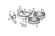
- FIG. 2 is a schematic configuration diagram of a biochemical analysis module in an automatic analysis system to which the present invention is applied.
- the biochemical module 7 includes a first reagent disk 43 in which a reagent container 41 for storing a plurality of first reagents and a reagent container 42 for storing a second reagent are arranged in a circle, A reagent system including a second reagent disk 44 and first and second reagent dispensing pipettors 45 and 46 is provided.
- a sample system including a sample dispensing pipetter 47, a reaction system in which a plurality of reaction vessels 50 are arranged on a reaction disk 49 in which constant temperature water from a constant temperature bath 48 circulates, and a multiwavelength photometer 52 are included.
- a measurement system analysis system
- the sample rack 30 is drawn into the lead-in line 71, held in the sample rack, and the sample (sample) positioned at the sample suction position is sucked by the sample dispensing pipettor 47, and the sample is put into the reaction container 50 of the reaction disk 49. Released at the pouring position.
- the reaction container 50 from which the sample has been released is moved to the first reagent dispensing position by the rotation of the reaction disk 49, where the first reaction disk 50 holds the first reagent disk 43.
- the reagent is held in the reagent bottle 41 and is dispensed by the first reagent pipetter 45.
- the reagent pipetter 45 has a liquid level detection function that accurately captures the liquid level of the reagent so that the reagent pipetter 45 does not penetrate into the reagent liquid at the time of reagent dispensing, so that the reagent pipetter 45 is not contaminated more than necessary. Yes.
- the reaction vessel 50 into which the first reagent has been dispensed is moved to a stirring position, where the sample and the first reagent are stirred by the stirring device 53.
- the stirred reaction container 50 is moved to the second reagent dispensing position, where the reaction container 50 is held on the second reagent disk 44.
- the second reagent accommodated in the reagent bottle 42 is dispensed by the second reagent pipetter 46.
- the dispensed reaction container 50 is moved to the stirring position, and the sample, the first reagent, and the second reagent in the reaction container 50 are stirred by the stirring device 53, and the reaction liquid is generated. .
- the reaction vessel 50 containing the reaction solution is moved to the measurement position, where the multi-wavelength photometry of the reaction solution is performed by the multi-wavelength photometer 52, and the analysis result of the biochemical analysis item is obtained.
- FIG. 3 is a diagram showing an analysis procedure in one embodiment of the present invention.
- the reaction vessel 50 is first cleaned by the reaction vessel cleaning mechanism (step 701).
- the sample 54 is dispensed by the sample dispensing pipettor 47, and the sample 54 is dispensed into the reaction container 50 (step 702).
- the first reagent is dispensed from the reagent container by the nozzle 451 of the reagent dispensing pipetter 45 for dispensing the first reagent and dispensed into the reaction container 50 (step 703).
- the specimen 54 and the first reagent in the reaction vessel 50 are stirred by the stirring mechanism to become the reaction solution 56 (step 704).
- the second reagent 57 is dispensed into the reaction vessel 50 by the nozzle 461 of the reagent dispensing pipetter 46 of the second reagent (step 705), and then stirred by the stirring mechanism 53 to become the reaction solution 58 (step 706). ).
- the light from the light source 415 passes through the reaction solution 58 and is received by the photometer 52, the absorbance of the reaction solution 58 is measured, and an analysis result is obtained (step 707).
- reaction vessel 50 that has been analyzed is washed again (step 701), and the sequence of preparing for the next measurement is repeated.
- reaction vessel 50 is arranged on the circumference and the photometer is rotated around the photometer a plurality of times. Since it passes, the photometry of the absorbance can be carried out a plurality of times.
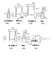
- FIG. 4 is an explanatory diagram of a reagent dispensing control cycle in one embodiment of the present invention.
- the reagent dispensing pipetter 46, the reagent disk 44, and the reagent bottle 42 perform the same operations as the reagent dispensing pipetter 45 and the reagent disk 443 reagent bottle 41.
- the reagent dispensing pipetter 45 moves to the reagent dispensing position, and the reagent disk 43 rotates the reagent bottle 41 to the reagent dispensing position (state 501).
- the liquid level inside the reagent bottle 41 is stationary before the reagent disk is rotated (state 504).
- the liquid level in the reagent bottle 41 is not stable due to the inertial force at the time of the rotation of the reagent disk. It is necessary to wait for a note (state 505).
- the reagent dispensing pipetter 45 After the reagent liquid level is stabilized (state 506), the reagent dispensing pipetter 45 performs a downward operation to the liquid level for reagent dispensing and dispenses the reagent (state 503).
- the nozzle 451 of the reagent dispensing pipetter 45 descends in the reagent bottle 41 while searching for the liquid level (state 507). After the nozzle 451 of the reagent dispensing pipetter 45 comes into contact with the reagent liquid surface (state 508), the nozzle 451 continues to move downward from the liquid surface by a specified amount (state 509).
- the descending distance from the liquid level may be a fixed amount from the liquid level because the liquid level drops by an amount proportional to the suction amount when the reagent is aspirated, or an amount proportional to the suction amount.
- the nozzle 451 of the reagent dispensing pipetter 45 aspirates a preset amount of reagent (state 510).
- the reagent dispensing pipetter 45 is raised (state 511), and a reagent dispensing control cycle in which the reagent dispensing pipet 45 moves away from the liquid surface to the reaction container 50 (not shown) and discharges the reagent is performed for each dispensing of each reagent bottle 41. repeat.
- FIG. 5 is a diagram illustrating an example of the types of reagent bottles mounted on the automatic analyzer according to the embodiment of the present invention.
- the reagent bottle 301 has a wide reagent mouth 411, when the nozzle 451 of the reagent dispensing pipetter 45 sucks the reagent, the suction operation is easy even if the stop position of the reagent dispensing pipetter 45 is slightly shifted. There is a feature that can be done. Further, the bottle shape is simple, and the manufacturing cost of the reagent bottle 301 can be suppressed. However, it takes time until the liquid shaking in the reagent container is settled after the reagent disk rotates.
- the reagent bottle 302 is provided with a cylindrical structure 412 in the reagent bottle 302 in order to suppress the liquid shaking as much as possible after the rotation of the reagent disk with respect to the reagent bottle 301 and to shorten the reagent dispensing operation time. Thereby, even when the reagent disk is rotated, the reagent liquid is less shaken in the cylindrical structure 412, and the liquid level of the reagent can be stabilized in a shorter time than the reagent bottle 301. Thus, the reagent dispensing operation can be started immediately after the reagent disk is rotated.
- the reagent bottle 303 is for a reagent that deteriorates quickly, and has a shape in which the reagent suction opening 413 is small.
- ALP alkaline phosphatase
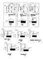
- FIG. 6 is a diagram showing a reagent liquid level detection method in the automatic analyzer according to the embodiment of the present invention.
- a method for detecting the liquid level of the reagent an optimum method is selected according to the shape of the reagent bottle shown in FIG.
- the capacitance method 401 sets the potential of the probe (nozzle) to V when the nozzle of the reagent dispensing pipettor 451 is in the air and when it contacts the liquid surface, grounds the reagent bottle 41, and air It is determined whether or not the reagent liquid surface has been reached by measuring the difference between the electrostatic capacity when it is inside and the electrostatic capacity when contacting the reagent.
- the electrical resistance method 402 uses the difference between the electrostatic capacity method 401 when the nozzle of the reagent dispensing pipettor is in the air and the liquid surface for determination, whereas the electrical resistance method 402 uses the electrical resistance. This is a liquid level detection method that captures the difference between the two.
- the capacitance method 401 and the electric resistance method 402 have high liquid level detection accuracy, but if the reagent dispensing pipetter nozzle contacts the reagent bottle 41 before reaching the liquid level, for example, the liquid level is erroneously detected. Therefore, it is preferable that the mouth opening of the reagent bottle 41 is large.
- the pressure detection method 403 is a method for detecting the liquid level by detecting the difference in pressure between when the probe is in the air and when it is at the liquid level.
- the nozzle of the reagent dispensing pipetter When the nozzle of the reagent dispensing pipetter is in the air, it is equal to the atmospheric pressure, but when reaching the liquid level, a difference in pressure caused by a difference in viscosity between the liquid and gas is detected.
- the optical detection system 404 is provided with a light source 415 and an optical sensor 416 for detecting the reagent liquid level on the side surface of the reagent bottle 41, and an optical sensor for determining whether the nozzle tip of the reagent dispensing pipettor crosses the optical sensor unit 416.
- the unit 416 detects whether the reagent pipetter has arrived at the liquid level.
- the liquid level detection accuracy is lower than in the capacitance method and the electric resistance method, but even if the nozzle of the reagent dispensing pipetter contacts the suction port of the reagent container. Since there is little possibility of erroneous detection as the liquid level of the reagent, the present invention can also be applied to a reagent bottle with a narrow reagent mouth opening.
- FIG. 7 is a diagram showing an example of an analysis parameter setting screen 500 in the automatic analyzer according to the embodiment of the present invention.
- the analysis parameters are the sample dispensing amount and reagent dispensing amount for each item when measuring a specific component contained in the sample. These are set and stored in advance in the device and registered as analysis parameters. Information is used.
- the information regarding the shape of the reagent bottle shown in FIG. 7 is registered in a non-contact information medium such as a barcode or RFID attached to the reagent bottle, and the reagent bottle is installed in the apparatus and then stored in the apparatus.
- the registered information written in each reagent bottle may be read and stored in the apparatus.
- reagent bottle information is set in item units in advance.
- the reagent suction opening information 521 of the reagent bottle, the presence / absence information 522 of the liquid shaking prevention means, the liquid level detection method information 523, the reagent disk rotates and moves to the reagent dispensing position.
- the operator sets the stabilization time information 524 from when the liquid level becomes stable to the liquid level using an information input unit such as a keyboard.
- the stabilization time information 524 until the stabilization is established is set by the operator using an information input unit such as a keyboard.
- these information can be stored on a non-contact information medium such as a barcode or RFID for a reagent bottle installed in the apparatus. Information can also be stored in the device by recording it in advance.
- the stability time of the reagent liquid level in the reagent bottle is N times the reagent dispensing control cycle.
- the reagent dispensing operation is stopped and only the reagent dispensing operation is stopped for one cycle before starting the reagent dispensing operation. It has become. During this time, the entire apparatus is not stopped, and the reaction vessel may be washed or the absorbance of the reaction solution may be measured.
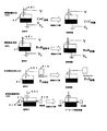
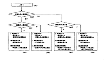
- FIG. 8 is a diagram showing a reagent dispensing operation determination flow in the automatic analyzer of one embodiment of the present invention
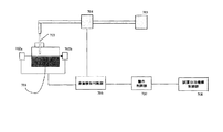
- FIG. 9 is a functional block diagram for executing the flow shown in FIG.
- the automatic analyzer shows an example in which an actual reagent dispensing operation is determined after an operator selects a reagent dispensing operation and a liquid level detection method on the screen 500 according to the shape of the reagent bottle.
- the actual reagent dispensing operation may be determined according to the information stored on the apparatus side by storing it in a non-contact type information medium such as a barcode or RFID attached to each reagent bottle.
- step 601 The operation is started in step 601 and before the reagent dispensing starts, the liquid level determination unit (computer) 419 first sets the reagent bottle shape information for each item set by the reagent bottle information input unit 500 to the reagent bottle. The presence or absence of a liquid shaking prevention mechanism is checked (step 602). If there is no liquid leakage prevention mechanism in step 602, the process proceeds to step 604, and it is determined whether the opening of the reagent bottle is small or large.
- step 604 the process proceeds to step 607 where the liquid level determination unit 419 determines whether one cycle has elapsed after the reagent disk drive unit 418 stopped the reagent disk. . After one cycle of stopping the reagent disk, the liquid level determination unit 419 notifies the operation control unit 9 to that effect.
- the operation control unit controls the reagent dispensing nozzle driving unit 422 according to the transmission signal from the liquid level determination unit 419, inserts the nozzle 451 into the reagent bottle 41, and lowers it.
- the liquid level determination unit 419 determines whether or not the nozzle 451 has reached the liquid level from the capacitance value detected by the capacitance detection unit 417. To the unit 420.
- step 604 determines whether one cycle has elapsed after the reagent disk drive unit 418 stops the reagent disk. to decide. After one cycle of stopping the reagent disk, the liquid level determination unit 419 notifies the operation control unit 9 to that effect.
- the operation control unit controls the reagent dispensing nozzle driving unit 422 according to the transmission signal from the liquid level determination unit 419, inserts the nozzle 451 into the reagent bottle 41, and lowers it.
- the liquid level determination unit 419 determines whether or not the nozzle 451 has reached the liquid level from the pressure value detected by the pressure sensor 414, and if it determines that the liquid level has been reached, transmits the fact to the operation control unit 420. .
- step 603 determines whether the opening of the reagent bottle is small or large.
- the opening of the reagent bottle has a large or small opening shape such as the reagent bottle 303 shown in FIG. 5, the opening is small, and the opening in the case of the reagent bottles 301 and 302 is large.
- step 603 If it is determined in step 603 that the opening of the reagent bottle is large, the process proceeds to step 605, where the liquid level determination unit 419 determines whether the reagent disk drive unit 418 has just stopped the reagent disk. Immediately after the reagent disk is stopped, the liquid level determination unit 419 notifies the operation control unit 9 to that effect.
- the operation control unit controls the reagent dispensing nozzle driving unit 422 according to the transmission signal from the liquid level determination unit 419, inserts the nozzle 451 into the reagent bottle 41, and lowers it.
- the liquid level determination unit 419 determines whether or not the nozzle 451 has reached the liquid level from the capacitance value detected by the capacitance detection unit 417. To the unit 420.
- step 603 if it is determined in step 603 that the opening of the reagent bottle is small, the process proceeds to step 606, where the liquid level determination unit 419 determines whether the reagent disk drive unit 418 has just stopped the reagent disk. Immediately after the reagent disk is stopped, the liquid level determination unit 419 notifies the operation control unit 9 to that effect.
- the operation control unit controls the reagent dispensing nozzle driving unit 422 according to the transmission signal from the liquid level determination unit 419, inserts the nozzle 451 into the reagent bottle 41, and lowers it.
- the liquid level determination unit 419 determines whether or not the nozzle 451 has reached the liquid level from the pressure value detected by the pressure sensor 414, and if it determines that the liquid level has been reached, transmits the fact to the operation control unit 420. .
- the pressure sensor 414 is attached in the vicinity of the pump 423 that controls the reagent suction and discharge of the nozzle, and detects the pressure in the nozzle.
- the liquid level detection method is set in the setting unit 500. If so, give priority to it.
- the nozzle level is determined from the output signals of both the capacitance detection unit 417 and the pressure sensor 414. It can also be configured to determine that it has been reached. For example, when the capacitance type is used, a reagent liquid level is generated, and when the tip of the probe comes into contact with the bubble, the capacitance value may change even though it does not reach the liquid level. .
- the pressure in the nozzle is also detected, and if the pressure in the nozzle does not fluctuate more than a certain value, it is determined that the liquid level is erroneously detected, the nozzle is further lowered, and then the capacitance value changes It can also be determined that the time has reached the liquid level.
- the liquid level stabilization time can be set automatically depending on whether or not the reagent bottle is provided with a liquid shaking prevention means. If the liquid level stabilization time is set by the setting unit 500, The liquid level stabilization time can also be given priority.
- FIG. 10 is a diagram showing a reagent dispensing operation determination flow in the automatic analyzer of the second embodiment of the present invention
- FIG. 11 is a functional block diagram for executing the flow shown in FIG.
- the information about the reagent bottle is determined in advance only by the liquid level detection means provided in the apparatus without requiring information from the non-contact type information medium added to the setting screen of the apparatus or the reagent bottle. It is tightening.
- step 711 the operation is started.
- the reagent dispensing mechanism 703 moves down to the liquid level of the reagent bottle 701.
- step 712 the apparatus recognizes the liquid level by the optical liquid level detection means (702a / b), and reports to the liquid level judgment unit 706 that the liquid level has been recognized.
- step 713 the pressure detection mechanism 704 provided in the flow path of the reagent dispensing mechanism 703 determines whether or not the liquid has actually reached the liquid level, and reports the result to the liquid level determination unit 706. .
- step 714 the reagent in the reagent bottle is actually aspirated.
- the operation control unit 707 controls the reagent dispensing nozzle drive unit 708 in accordance with the transmission signal from the liquid level determination unit 706.
- the reagent dispensing mechanism 703 further returns by a certain amount and then returns to step 713 to reach the liquid level
- the operation control unit 707 controls the reagent dispensing nozzle driving unit 708 according to the transmission signal from the liquid level determination unit 706.
- 10 and 11 show a determination flow based on a combination of the optical detection method and the pressure detection method, but the selection may be made in combination with a capacitance method, an electric resistance method, or the like.
- an appropriate liquid level detection method and liquid level stabilization time are selected according to the type of reagent bottle to be used (size of reagent suction opening, presence / absence of liquid shaking prevention means). Since the reagent dispensing operation is controlled, the reagent dispensing operation suitable for the reagent container is possible when using a reagent container of a type suitable for the chemical characteristics of the reagent. It is possible to realize an automatic analyzer and an automatic analysis method with high reliability and high processing capability.
- the above-described example is an example in the case where the present invention is applied to an automatic analysis system having a plurality of analysis modules, but can also be applied to an automatic analysis apparatus.
- FIG. 12 is a diagram showing the overall configuration of the automatic analyzer described above.
- a reaction disk 101 provided so as to be intermittently rotated has a large number of reaction vessels 120 made of a translucent material mounted along the circumference.
- the reaction vessel 120 is maintained at a predetermined temperature (for example, 37 ° C.) by the thermostatic chamber 141.
- the temperature of the fluid in the constant temperature bath 141 is adjusted by the constant temperature maintaining device 161.
- a large number of specimen containers 221 containing biological samples such as blood or urine are arranged on the sample disk 201.
- a pipette nozzle 261 attached to the movable arm 241 sucks a predetermined amount of sample from the specimen container 221 positioned at the suction position of the sample disk 201, and the sample is in the reaction container 120 at the discharge position on the reaction disk 101. To discharge.
- a plurality of reagent bottles 32A and 32B with labels displaying reagent identification information such as barcodes are arranged on the reagent disks arranged in the reagent cold storages 30A and 30B, respectively.
- These reagent bottles 32A and 32B contain reagent solutions corresponding to analysis items that can be analyzed by the analyzer.
- the barcode reader attached to each reagent cooler 30A, 30B reads the barcode displayed on the outer wall of each reagent bottle at the time of reagent registration.
- the read reagent information is registered in the memory 56 described later together with the position on the reagent disk.
- each reagent dispensing mechanism 36A, 36B sucks the reagent solution from the reagent bottle corresponding to the inspection item positioned at the reagent receiving position on the reaction disk 101 and discharges it into the corresponding reaction container 120.
- the mixture of the sample and the reagent accommodated in the reaction vessel 120 is stirred by the stirring mechanisms 38A and 38B.
- the rows of reaction vessels 120 are rotationally moved so as to pass through a photometric position sandwiched between the white light source 401 and the multi-wavelength photometer 421.
- reaction liquid of the sample and the reagent in each reaction container 120 is photometrically measured while the reaction disk 101 is rotating.
- the analog signal measured for each sample is input to the A / D converter 441.
- the reaction container cleaning mechanism 180 disposed in the vicinity of the reaction disk 101 allows the reaction container to be used repeatedly by cleaning the inside of the used reaction container 120.
- the computer 501 is connected to the sample dispensing control unit 281, the reagent dispensing control unit 391, and the A / D converter 441 via the interface 521.
- the computer 501 sends a command to the sample dispensing control unit 281 to control the sample dispensing operation.
- the computer 501 also sends a command to the reagent dispensing control unit 391 to control the reagent dispensing operation.
- the photometric value converted into a digital signal by the A / D converter 441 is taken into the computer 501.
- the interface 521 is connected to a printer 54 for printing, a memory 56 as a storage device, a flexible magnetic disk drive 58, a keyboard 60 for inputting operation commands and the like, and a CRT display 100 for screen display.
- the memory 56 is configured by, for example, a hard disk memory or an external memory.
- the memory 56 stores information such as the password of each operator, the display level of each screen, analysis parameters, analysis item request contents, calibration results, and analysis results.
- Analysis parameters relating to items that can be analyzed by the automatic analyzer are previously input via an information input device such as the keyboard 60 and stored in the memory 56.
- the operator selects an inspection item requested for each sample using an operation function screen described later.
- information such as a patient ID is also input from the keyboard 60.
- the pipette nozzle 261 dispenses a predetermined amount of sample from the specimen container 221 to the reaction container 120 according to the analysis parameter.
- the reaction container that has received the sample is transferred by the rotation of the reaction disk 101 and stops at the reagent receiving position.
- the pipette nozzles of the reagent dispensing mechanisms 36A and 36B dispense a predetermined amount of reagent solution into the reaction container 120 according to the analysis parameter of the corresponding inspection item.
- the dispensing order of the sample and the reagent may be reversed from this example, and the reagent may precede the sample.
- the sample and the reagent are agitated and mixed by the agitating mechanisms 38A and 38B.
- the absorbance of the reaction solution is measured by the multi-wavelength photometer 421.
- the measured absorbance is taken into the computer 501 via the A / D converter 441 and the interface 521.
- This absorbance is converted into concentration data based on a calibration curve measured in advance by an analysis method designated for each inspection item. Component concentration data as an analysis result of each inspection item is output to the screen of the printer 54 or the CRT 100.
- the operator sets various parameters necessary for analytical measurement and registers the sample via the operation screen.
- the operator confirms the analysis result after measurement on the operation screen on the CRT 100.
- the present invention is also applicable to the automatic analyzer shown in FIG.
Abstract
Description
(2)試薬分取時に試薬容器内の液面の揺れが少ないこと。
一方、ステップ713にて圧力検知機構704の判断により、液面でないと判断した場合にはステップ715にて試薬分注機構703は更に一定量、下降した後にステップ713に戻り液面に到着したか確認した後に動作制御部707は、液面判断部706からの伝達信号に従って、試薬分注ノズル駆動部708を制御する。
なお図10,11には、光学的検知方式と圧力検知方式の組み合わせによる判断フローを示しているが、静電容量方式、電気抵抗方式などと組み合わせて選択しても良い。
Claims (8)
- ノズル(451)を試薬容器(41)の開口部に挿入し、試薬容器(41)内の試薬を吸引し、反応容器(50)内に吐出する試薬吸引吐出手段(45、46)を有する自動分析装置において、
試薬容器(41)の開口部の大小が入力される試薬容器情報入力手段(500)と、
上記ノズル(451)が上記試薬容器(41)内の試薬液面に到達したことを検出する複数種類の液面到達検出手段(414、417)と、
上記試薬容器情報入力手段(500)から入力された情報に従って、上記複数種類の液面到達検出手段(414、417)のうちのいずれかを選択し、選択した液面到達検出手段(414、417)からの液面到達検出信号に基づいて、上記試薬吸引吐出手段(45、46)の試薬吸引動作を制御する動作制御手段(420)と、
を備えることを特徴とする自動分析装置。 - 請求項1記載の自動分析装置において、上記試薬容器(41)を上記試薬吸引吐出手段(45、46)が試薬を吸引する試薬吸引位置に移動させる試薬容器移動手段(43、44)を備え、上記試薬容器情報入力手段(500)には、試薬容器(41)が液揺れ防止手段(412)を有するか否かの情報が入力され、上記動作制御手段(420)は、上記試薬容器情報入力手段(500)から入力された、液揺れ防止手段(412)を有するか否かの情報に従って、上記試薬容器移動手段(43、44)が試薬容器(41)を上記試薬吸引位置に移動させた後から上記試薬吸引吐出手段(45、46)による試薬吸引動作を開始するまでの試薬吸引動作開始時間を変更することを特徴とする自動分析装置。
- 請求項2記載の自動分析装置において、上記動作制御手段(420)は、上記試薬容器(41)が液揺れ防止手段(412)を有する場合における、上記試薬吸引動作開始時間を、上記試薬容器(41)が液揺れ防止手段(412)を有していない場合の上記試薬吸引動作開始時間より短時間とすることを特徴とする自動分析装置。
- 請求項2記載の自動分析装置において、上記複数種類の液面到達検出手段(414、417)は、上記ノズル(451)と上記試薬容器(41)との間の静電容量値を検出し、検出した静電容量値の変化に基づき上記ノズル(451)が試薬液面に到達したことを検知する静電容量式液面到達検出手段(417)と、上記ノズル(451)内の圧力を検出し、検出した圧力の変化に基づき上記ノズル(451)が試薬液面に到達したことを検知する圧力検知式液面到達検出手段(414)とであり、上記動作制御手段(420)は、上記試薬容器(41)の開口部が大の場合は、上記静電容量式液面到達検出手段(417)からの液面検出信号に基づいて上記試薬吸引吐出手段(45、46)の試薬吸引動作を制御し、上記試薬容器(41)の開口部が小の場合は、上記圧力検知式液面到達検出手段(414)からの液面検出信号に基づいて上記試薬吸引吐出手段(45、46)の試薬吸引動作を制御することを特徴とする自動分析装置。
- ノズル(451)を試薬容器(41)の開口部に挿入し、試薬容器(41)内の試薬を吸引し、試料を収容する反応容器(50)内に吐出し、反応容器(50)内の混合液を分析する自動分析方法において、
試薬容器(41)の開口部の大小を入力し、試薬容器情報入力手段(500)から入力された情報に従って、上記ノズル(451)が上記試薬容器(41)内の試薬液面に到達したことを複数種類の液面到達検出手段(414、417)のうちのいずれかを選択し、選択した液面到達検出手段(414、417)からの液面到達検出信号に基づいて、上記ノズル(451)の試薬吸引動作を制御することを特徴とする自動分析方法。 - 請求項5記載の自動分析方法において、上記試薬容器(41)は、上記ノズル(451)が試薬を吸引する試薬吸引位置に試薬容器移動手段(43、44)により移動され、上記試薬容器情報入力手段(500)には、試薬容器(41)が液揺れ防止手段(412)を有するか否かの情報が入力され、上記試薬容器情報入力手段(500)から入力された、液揺れ防止手段(412)を有するか否かの情報に従って、上記試薬容器移動手段(43、44)が試薬容器(41)を上記試薬吸引位置に移動させた後から上記ノズル(451)による試薬吸引動作を開始するまでの試薬吸引動作開始時間を変更することを特徴とする自動分析方法。
- 請求項6記載の自動分析方法において、上記試薬容器(41)が液揺れ防止手段(412)を有する場合における、上記試薬吸引動作開始時間を、上記試薬容器(41)が液揺れ防止手段(412)を有していない場合の上記試薬吸引動作開始時間より短時間とすることを特徴とする自動分析方法。
- 請求項6記載の自動分析方法において、上記複数種類の液面到達検出手段(414、417)は、上記ノズル(451)と上記試薬容器(41)との間の静電容量値を検出し、検出した静電容量値の変化に基づき上記ノズル(451)が試薬液面に到達したことを検知する静電容量式液面到達検出手段(417)と、上記ノズル(451)内の圧力を検出し、検出した圧力の変化に基づき上記ノズル(451)が試薬液面に到達したことを検知する圧力検知式液面到達検出手段(414)とであり、上記試薬容器(41)の開口部が大の場合は、上記静電容量式液面到達検出手段(417)からの液面検出信号に基づいて上記ノズル(451)の試薬吸引動作を制御し、上記試薬容器(41)の開口部が小の場合は、上記圧力検知式液面到達検出手段(414)からの液面検出信号に基づいて上記ノズルの試薬吸引動作を制御することを特徴とする自動分析方法。
Priority Applications (4)
| Application Number | Priority Date | Filing Date | Title |
|---|---|---|---|
| EP09766497.3A EP2293083B1 (en) | 2008-06-17 | 2009-05-12 | Automatic analyzer |
| CN2009801225936A CN102066949B (zh) | 2008-06-17 | 2009-05-12 | 自动分析装置 |
| JP2010517814A JP5178830B2 (ja) | 2008-06-17 | 2009-05-12 | 自動分析装置 |
| US12/996,414 US20110104810A1 (en) | 2008-06-17 | 2009-05-12 | Automatic analyzer |
Applications Claiming Priority (2)
| Application Number | Priority Date | Filing Date | Title |
|---|---|---|---|
| JP2008158285 | 2008-06-17 | ||
| JP2008-158285 | 2008-06-17 |
Publications (1)
| Publication Number | Publication Date |
|---|---|
| WO2009154049A1 true WO2009154049A1 (ja) | 2009-12-23 |
Family
ID=41433965
Family Applications (1)
| Application Number | Title | Priority Date | Filing Date |
|---|---|---|---|
| PCT/JP2009/058864 WO2009154049A1 (ja) | 2008-06-17 | 2009-05-12 | 自動分析装置 |
Country Status (5)
| Country | Link |
|---|---|
| US (1) | US20110104810A1 (ja) |
| EP (1) | EP2293083B1 (ja) |
| JP (1) | JP5178830B2 (ja) |
| CN (1) | CN102066949B (ja) |
| WO (1) | WO2009154049A1 (ja) |
Cited By (4)
| Publication number | Priority date | Publication date | Assignee | Title |
|---|---|---|---|---|
| CN102297934A (zh) * | 2010-06-24 | 2011-12-28 | 希森美康株式会社 | 检测体分析装置以及液体吸引方法 |
| JP2013068432A (ja) * | 2011-09-20 | 2013-04-18 | Hitachi High-Technologies Corp | 自動分析装置及びその動作不良判定方法 |
| JP2013072710A (ja) * | 2011-09-27 | 2013-04-22 | Sysmex Corp | 検体分析装置 |
| JP2015057614A (ja) * | 2014-12-22 | 2015-03-26 | 株式会社日立ハイテクノロジーズ | 自動分析装置 |
Families Citing this family (17)
| Publication number | Priority date | Publication date | Assignee | Title |
|---|---|---|---|---|
| JP5517467B2 (ja) * | 2009-02-20 | 2014-06-11 | 株式会社日立ハイテクノロジーズ | 自動分析装置 |
| JP2013210265A (ja) * | 2012-03-30 | 2013-10-10 | Sysmex Corp | 検体分析装置、精度管理用検体ユニットおよび精度管理方法 |
| JP5917693B2 (ja) * | 2012-07-09 | 2016-05-18 | 富士フイルム株式会社 | 呈色測定装置および方法 |
| EP2816345A1 (en) | 2013-06-19 | 2014-12-24 | Roche Diagniostics GmbH | Electrochemiluminescence method of detecting an analyte in a liquid sample and analysis system |
| WO2015079829A1 (ja) * | 2013-11-26 | 2015-06-04 | 株式会社 日立ハイテクノロジーズ | 自動分析装置 |
| WO2016025849A1 (en) | 2014-08-15 | 2016-02-18 | Biomerieux, Inc. | Methods, systems, and computer program products for detecting pipette tip integrity |
| ES2898649T3 (es) | 2015-07-13 | 2022-03-08 | Siemens Healthcare Diagnostics Products Gmbh | Procedimiento para el pipeteo de líquidos en un aparato analizador automático |
| JP6837362B2 (ja) * | 2017-03-17 | 2021-03-03 | 株式会社日立ハイテク | 自動分析装置 |
| JP6916677B2 (ja) * | 2017-06-27 | 2021-08-11 | アークレイ株式会社 | ノズル洗浄装置、分注装置、分析装置、ノズルの洗浄方法 |
| WO2019026498A1 (ja) * | 2017-08-01 | 2019-02-07 | 株式会社日立ハイテクノロジーズ | 自動分析装置 |
| JP6435387B1 (ja) * | 2017-09-29 | 2018-12-05 | シスメックス株式会社 | カートリッジ、検出方法、および検出装置 |
| WO2019176298A1 (ja) * | 2018-03-15 | 2019-09-19 | 株式会社日立ハイテクノロジーズ | 自動分析装置 |
| EP3779468B1 (en) * | 2018-04-12 | 2023-08-16 | Hitachi High-Tech Corporation | Electrolyte analyzing device |
| EP3896454B1 (en) * | 2018-12-11 | 2024-03-20 | Hitachi High-Tech Corporation | Automated analyzer |
| JP7171506B2 (ja) * | 2019-04-24 | 2022-11-15 | 株式会社日立ハイテク | 自動分析装置、及び方法 |
| JP7243607B2 (ja) * | 2019-12-12 | 2023-03-22 | 株式会社島津製作所 | 生化学分析装置および生化学分析方法 |
| CN112611480A (zh) * | 2020-11-27 | 2021-04-06 | 中冶赛迪工程技术股份有限公司 | 一种测温取样方法及系统 |
Citations (7)
| Publication number | Priority date | Publication date | Assignee | Title |
|---|---|---|---|---|
| JPS63109373A (ja) * | 1986-10-27 | 1988-05-14 | Kyoto Daiichi Kagaku:Kk | サンプリング方法及びその装置 |
| JPH0915024A (ja) * | 1995-06-30 | 1997-01-17 | Kdk Corp | 液面検知装置 |
| JP2001004641A (ja) * | 1999-06-18 | 2001-01-12 | Hitachi Ltd | 液面検出機能を備えた自動分析装置 |
| JP2003294774A (ja) * | 2002-04-01 | 2003-10-15 | Olympus Optical Co Ltd | 自動分析装置 |
| JP2005083777A (ja) | 2003-09-05 | 2005-03-31 | Hitachi High-Technologies Corp | 分析装置及び試薬容器 |
| JP2005164509A (ja) * | 2003-12-05 | 2005-06-23 | Hitachi High-Technologies Corp | 試薬容器 |
| JP2007285888A (ja) * | 2006-04-17 | 2007-11-01 | Olympus Corp | 液面検知装置および自動分析装置 |
Family Cites Families (8)
| Publication number | Priority date | Publication date | Assignee | Title |
|---|---|---|---|---|
| US4736638A (en) * | 1985-12-20 | 1988-04-12 | Beckman Instruments, Inc. | Liquid level sensor |
| JPH1183867A (ja) * | 1997-09-02 | 1999-03-26 | Olympus Optical Co Ltd | 分注装置 |
| EP0913671A1 (de) * | 1997-10-29 | 1999-05-06 | Roche Diagnostics GmbH | Verfahren und Vorrichtung zum Flüssigkeitstransfer mit einem Analysegerät |
| JP2000046624A (ja) * | 1998-07-30 | 2000-02-18 | Sysmex Corp | 液体残量検出機能を備えた分析装置 |
| JP4095968B2 (ja) * | 2004-02-06 | 2008-06-04 | 株式会社日立ハイテクノロジーズ | 液体分注装置、それを用いた自動分析装置、及び液面検出装置 |
| JP4700563B2 (ja) * | 2005-06-15 | 2011-06-15 | 株式会社日立国際電気 | データ伝送方法およびデータ伝送システム |
| DE102006034245C5 (de) * | 2006-07-21 | 2014-05-28 | Stratec Biomedical Systems Ag | Positioniereinrichtung zur Positionierung von Pipetten |
| JP2009174869A (ja) * | 2008-01-21 | 2009-08-06 | Olympus Corp | 分注装置、自動分析装置、分注装置の制御プログラム、および分注方法 |
-
2009
- 2009-05-12 US US12/996,414 patent/US20110104810A1/en not_active Abandoned
- 2009-05-12 CN CN2009801225936A patent/CN102066949B/zh active Active
- 2009-05-12 WO PCT/JP2009/058864 patent/WO2009154049A1/ja active Application Filing
- 2009-05-12 EP EP09766497.3A patent/EP2293083B1/en active Active
- 2009-05-12 JP JP2010517814A patent/JP5178830B2/ja active Active
Patent Citations (7)
| Publication number | Priority date | Publication date | Assignee | Title |
|---|---|---|---|---|
| JPS63109373A (ja) * | 1986-10-27 | 1988-05-14 | Kyoto Daiichi Kagaku:Kk | サンプリング方法及びその装置 |
| JPH0915024A (ja) * | 1995-06-30 | 1997-01-17 | Kdk Corp | 液面検知装置 |
| JP2001004641A (ja) * | 1999-06-18 | 2001-01-12 | Hitachi Ltd | 液面検出機能を備えた自動分析装置 |
| JP2003294774A (ja) * | 2002-04-01 | 2003-10-15 | Olympus Optical Co Ltd | 自動分析装置 |
| JP2005083777A (ja) | 2003-09-05 | 2005-03-31 | Hitachi High-Technologies Corp | 分析装置及び試薬容器 |
| JP2005164509A (ja) * | 2003-12-05 | 2005-06-23 | Hitachi High-Technologies Corp | 試薬容器 |
| JP2007285888A (ja) * | 2006-04-17 | 2007-11-01 | Olympus Corp | 液面検知装置および自動分析装置 |
Cited By (5)
| Publication number | Priority date | Publication date | Assignee | Title |
|---|---|---|---|---|
| CN102297934A (zh) * | 2010-06-24 | 2011-12-28 | 希森美康株式会社 | 检测体分析装置以及液体吸引方法 |
| CN102297934B (zh) * | 2010-06-24 | 2015-05-20 | 希森美康株式会社 | 检测体分析装置以及液体吸引方法 |
| JP2013068432A (ja) * | 2011-09-20 | 2013-04-18 | Hitachi High-Technologies Corp | 自動分析装置及びその動作不良判定方法 |
| JP2013072710A (ja) * | 2011-09-27 | 2013-04-22 | Sysmex Corp | 検体分析装置 |
| JP2015057614A (ja) * | 2014-12-22 | 2015-03-26 | 株式会社日立ハイテクノロジーズ | 自動分析装置 |
Also Published As
| Publication number | Publication date |
|---|---|
| EP2293083A4 (en) | 2017-08-30 |
| JP5178830B2 (ja) | 2013-04-10 |
| JPWO2009154049A1 (ja) | 2011-11-24 |
| CN102066949A (zh) | 2011-05-18 |
| EP2293083B1 (en) | 2018-09-05 |
| EP2293083A1 (en) | 2011-03-09 |
| CN102066949B (zh) | 2013-06-12 |
| US20110104810A1 (en) | 2011-05-05 |
Similar Documents
| Publication | Publication Date | Title |
|---|---|---|
| JP5178830B2 (ja) | 自動分析装置 | |
| US10908175B2 (en) | Sample analyzer and liquid aspirating method | |
| US6319718B1 (en) | Handling method of body fluid sample and analysis apparatus using the same | |
| US6579717B1 (en) | Specific solution handling method for calibration and quality control by automatic analytical apparatus | |
| WO2007139212A1 (ja) | 自動分析装置 | |
| JP2004271265A (ja) | 自動分析装置 | |
| JP5097466B2 (ja) | 自動分析装置 | |
| JP4891749B2 (ja) | 自動分析装置 | |
| JP7189339B2 (ja) | 自動分析装置 | |
| EP2075587B1 (en) | Automatic analyzer and dispensing method thereof | |
| JP4416579B2 (ja) | 自動分析装置 | |
| JPH10232234A (ja) | 自動分析装置 | |
| JP7080391B2 (ja) | 自動分析装置 | |
| JP2011007719A (ja) | 自動分析装置 | |
| JP7461963B2 (ja) | 自動分析装置および試薬の分注方法 | |
| JP5258090B2 (ja) | 自動分析装置 | |
| JP2005164506A (ja) | 自動分析装置 | |
| JP6338898B2 (ja) | 自動分析装置 | |
| WO2022176556A1 (ja) | 自動分析装置、および自動分析装置における検体の吸引方法 | |
| WO2023008069A1 (ja) | 自動分析装置、および自動分析装置でのガイダンス方法 | |
| JP2023068295A (ja) | 洗剤ボトル及び自動分析装置 | |
| CN110730910A (zh) | 自动分析装置 |
Legal Events
| Date | Code | Title | Description |
|---|---|---|---|
| WWE | Wipo information: entry into national phase |
Ref document number: 200980122593.6 Country of ref document: CN |
|
| 121 | Ep: the epo has been informed by wipo that ep was designated in this application |
Ref document number: 09766497 Country of ref document: EP Kind code of ref document: A1 |
|
| WWE | Wipo information: entry into national phase |
Ref document number: 2010517814 Country of ref document: JP |
|
| WWE | Wipo information: entry into national phase |
Ref document number: 2009766497 Country of ref document: EP |
|
| WWE | Wipo information: entry into national phase |
Ref document number: 12996414 Country of ref document: US |
|
| NENP | Non-entry into the national phase |
Ref country code: DE |