WO2009142102A1 - ウィンドウガラス破損検出用クリップ - Google Patents
ウィンドウガラス破損検出用クリップ Download PDFInfo
- Publication number
- WO2009142102A1 WO2009142102A1 PCT/JP2009/058452 JP2009058452W WO2009142102A1 WO 2009142102 A1 WO2009142102 A1 WO 2009142102A1 JP 2009058452 W JP2009058452 W JP 2009058452W WO 2009142102 A1 WO2009142102 A1 WO 2009142102A1
- Authority
- WO
- WIPO (PCT)
- Prior art keywords
- window glass
- detected
- clip
- magnet
- broken
- Prior art date
- Legal status (The legal status is an assumption and is not a legal conclusion. Google has not performed a legal analysis and makes no representation as to the accuracy of the status listed.)
- Ceased
Links
Images











Classifications
-
- G—PHYSICS
- G08—SIGNALLING
- G08B—SIGNALLING SYSTEMS, e.g. PERSONAL CALLING SYSTEMS; ORDER TELEGRAPHS; ALARM SYSTEMS
- G08B13/00—Burglar, theft or intruder alarms
- G08B13/02—Mechanical actuation
- G08B13/04—Mechanical actuation by breaking of glass
-
- E—FIXED CONSTRUCTIONS
- E05—LOCKS; KEYS; WINDOW OR DOOR FITTINGS; SAFES
- E05F—DEVICES FOR MOVING WINGS INTO OPEN OR CLOSED POSITION; CHECKS FOR WINGS; WING FITTINGS NOT OTHERWISE PROVIDED FOR, CONCERNED WITH THE FUNCTIONING OF THE WING
- E05F11/00—Man-operated mechanisms for operating wings, including those which also operate the fastening
- E05F11/38—Man-operated mechanisms for operating wings, including those which also operate the fastening for sliding windows, e.g. vehicle windows, to be opened or closed by vertical movement
- E05F11/382—Man-operated mechanisms for operating wings, including those which also operate the fastening for sliding windows, e.g. vehicle windows, to be opened or closed by vertical movement for vehicle windows
- E05F11/385—Fixing of window glass to the carrier of the operating mechanism
-
- E—FIXED CONSTRUCTIONS
- E05—LOCKS; KEYS; WINDOW OR DOOR FITTINGS; SAFES
- E05F—DEVICES FOR MOVING WINGS INTO OPEN OR CLOSED POSITION; CHECKS FOR WINGS; WING FITTINGS NOT OTHERWISE PROVIDED FOR, CONCERNED WITH THE FUNCTIONING OF THE WING
- E05F11/00—Man-operated mechanisms for operating wings, including those which also operate the fastening
- E05F11/38—Man-operated mechanisms for operating wings, including those which also operate the fastening for sliding windows, e.g. vehicle windows, to be opened or closed by vertical movement
- E05F11/44—Man-operated mechanisms for operating wings, including those which also operate the fastening for sliding windows, e.g. vehicle windows, to be opened or closed by vertical movement operated by one or more lifting arms
- E05F11/445—Man-operated mechanisms for operating wings, including those which also operate the fastening for sliding windows, e.g. vehicle windows, to be opened or closed by vertical movement operated by one or more lifting arms for vehicle windows
-
- E—FIXED CONSTRUCTIONS
- E05—LOCKS; KEYS; WINDOW OR DOOR FITTINGS; SAFES
- E05Y—INDEXING SCHEME ASSOCIATED WITH SUBCLASSES E05D AND E05F, RELATING TO CONSTRUCTION ELEMENTS, ELECTRIC CONTROL, POWER SUPPLY, POWER SIGNAL OR TRANSMISSION, USER INTERFACES, MOUNTING OR COUPLING, DETAILS, ACCESSORIES, AUXILIARY OPERATIONS NOT OTHERWISE PROVIDED FOR, APPLICATION THEREOF
- E05Y2400/00—Electronic control; Electrical power; Power supply; Power or signal transmission; User interfaces
- E05Y2400/10—Electronic control
- E05Y2400/44—Sensors not directly associated with the wing movement
-
- E—FIXED CONSTRUCTIONS
- E05—LOCKS; KEYS; WINDOW OR DOOR FITTINGS; SAFES
- E05Y—INDEXING SCHEME ASSOCIATED WITH SUBCLASSES E05D AND E05F, RELATING TO CONSTRUCTION ELEMENTS, ELECTRIC CONTROL, POWER SUPPLY, POWER SIGNAL OR TRANSMISSION, USER INTERFACES, MOUNTING OR COUPLING, DETAILS, ACCESSORIES, AUXILIARY OPERATIONS NOT OTHERWISE PROVIDED FOR, APPLICATION THEREOF
- E05Y2900/00—Application of doors, windows, wings or fittings thereof
-
- E—FIXED CONSTRUCTIONS
- E05—LOCKS; KEYS; WINDOW OR DOOR FITTINGS; SAFES
- E05Y—INDEXING SCHEME ASSOCIATED WITH SUBCLASSES E05D AND E05F, RELATING TO CONSTRUCTION ELEMENTS, ELECTRIC CONTROL, POWER SUPPLY, POWER SIGNAL OR TRANSMISSION, USER INTERFACES, MOUNTING OR COUPLING, DETAILS, ACCESSORIES, AUXILIARY OPERATIONS NOT OTHERWISE PROVIDED FOR, APPLICATION THEREOF
- E05Y2900/00—Application of doors, windows, wings or fittings thereof
- E05Y2900/50—Application of doors, windows, wings or fittings thereof for vehicles
- E05Y2900/53—Type of wing
- E05Y2900/55—Windows
Definitions
- the present invention relates to a window glass breakage detection clip.
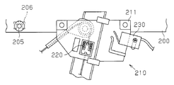
- Patent Document 1 discloses a device that detects a break in a window glass of a vehicle to prevent theft.
- the apparatus is configured to attach the carrier plate 211 of the cable-type window regulator 210 that supports the window glass 200 to the window glass 200.
- the compression coil spring 220 is urged in the closing direction.
- the limit switch 230 detects the breakage of the window glass 200 by detecting the movement of the carrier plate 211.
- tempered glass is usually used for the window glass 200. Although this window glass breaks into pieces when an impact is applied, a part of the window glass may remain without being crushed. In particular, in the detection device, when the window glass 200 remains in the vicinity of the carrier plate 211, the carrier plate 211 does not move in the closing direction, and there is a possibility that the breakage of the window glass 200 is not detected.
- Japanese Patent Laid-Open No. 11-321564 Japanese Patent Laid-Open No. 11-321564
- An object of the present invention is to provide a window glass breakage detection clip capable of reliably detecting breakage of a window glass even when the window glass remains without being completely pulverized due to breakage of the window glass. .
- a window glass breakage detection clip used for detecting breakage of a window glass based on a change in an arrangement state of a member to be detected with respect to the window glass of a vehicle.
- the breakage detection clip includes a first member and a second member that are bent so as to face each other and sandwich an end portion of the window glass.
- the first member and the second member are in contact with the window glass at positions shifted from each other in the plane of the window glass with the window glass disposed therebetween. At the same time, it is biased in the direction of approaching each other by its own elasticity.
- the first member and the second member are elastically deformed so as to crush the end portion of the window glass, thereby changing the arrangement state of the detected member with respect to the window glass.
- FIG. 4 is an exploded perspective view of a right front door of a passenger car to which the breakage detection apparatus according to the first to third embodiments of the present invention is applied.
- the schematic front view of the right front door of FIG. FIG. 3 is a longitudinal sectional view taken along line 3-3 in FIG.
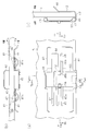
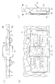
- (A) is a front view of the clip of FIG. 4,
- (b) is a plan view, and (c) is a side view.
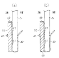
- FIG. 6A is a cross-sectional view taken along line 6a-6a of the clip shown in FIG. 5A, and FIG.
- FIG. 6B is a cross-sectional view taken along line 6b-6b of the clip shown in FIG.
- FIG. 7A is a cross-sectional view taken along line 7a-7a of the clip of FIG. 5A
- FIG. 5B is a cross-sectional view taken along line 7b-7b of the clip of FIG.
- (A) is a front view of the clip of FIG. 4,
- (b) is a plan view, and
- (c) is a side view.
- A) is a front view of the clip of FIG. 4,
- (b) is a plan view, and (c) is a side view.
- FIG. 10A is a cross-sectional view taken along the line 10a-10a of the clip of FIG. 9A
- FIG. 10B is a cross-sectional view taken along the line 10b-10b of the clip of FIG.
- FIG. 9A is a cross-sectional view taken along line 11a-11a of the clip of FIG. 9A
- FIG. 9B is a cross-sectional view taken along line 11b-11b of FIG.
- FIG. 4 is an output characteristic diagram of each magnetic sensor in FIG. 3.
- FIG. 4 is a characteristic diagram of the sum of outputs of both magnetic sensors in FIG. 3.
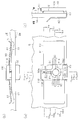
- (A) is a rear view of the clip of FIG. 14,
- (b) is a plan view, and
- (c) is a side view.
- FIG. 16D is a sectional view taken along line 16c-16c
- FIG. 16D is a sectional view taken along line 16d-16d in FIG. 15A is a cross-sectional view taken along line 17a-17a in FIG. 15A
- FIG. 15B is a cross-sectional view taken along line 17b-17b in FIG. 15A
- FIG. 15C is a cross-sectional view taken along line 17a-17a in FIG.
- FIG. 14 Sectional drawing along line 17c-17c.
- (A) is a rear view of the clip of FIG. 14, (b) is a plan view, and (c) is a side view.
- (A) is a rear view of the clip of FIG. 14, (b) is a plan view, and (c) is a side view.
- (A) is a rear view of the clip of FIG. 14, (b) is a plan view, and (c) is a side view.
- the perspective view of the damage detection apparatus containing the clip and sensor unit which concern on the 3rd Embodiment of this invention.
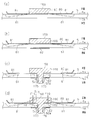
- (A) is a rear view of the clip of FIG. 21, (b) is a plan view, and (c) is a side view.
- FIG. 22A is a cross-sectional view taken along line 23a-23a in FIG. 22 (a)
- (b) is a cross-sectional view taken along line 23b-23b in FIG. 22 (a)
- (c) is a cross-sectional view taken along line 23a-23a in FIG.
- FIG. 23D is a cross-sectional view taken along line 23c-23c
- FIG. 22B is a cross-sectional view taken along line 24b-24b in FIG.
- FIG. 22 is a characteristic diagram of the sum of outputs of both magnetic sensors in FIG. 21.
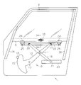
- FIG. 1 is an exploded perspective view of a right front door in a passenger car
- FIG. 2 is a schematic front view of the right front door of FIG.
- the vehicle door 1 includes an outer panel 2 and an inner panel 3.
- a window glass 5 made of tempered glass is disposed between the outer panel 2 and the inner panel 3.
- the thickness of the window glass 5 is about 3.1 mm to 5.0 mm.
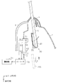
- a door trim 8 is attached to the inner side of the inner panel 3 (see FIG. 3).
- a window regulator 10 that moves the window glass 5 up and down is housed.
- an X-arm type window regulator is used as the window regulator 10.
- the inner panel 3 is provided with a door part assembly hole 3a, and a modular panel 6 is provided so as to close the door part assembly hole 3a.
- the X-arm type window regulator 10 is supported on the outer surface of the modular panel 6 via a base plate (fixed base) 11. That is, the shaft 13 of the lift arm 12 of the X arm type window regulator 10 is supported on the base plate 11 fixed to the outer surface of the modular panel 6.
- An electric drive unit 14 is fixed to the base plate 11.
- the lift arm 12 integrally has a sector gear (driven gear) 15 having a shaft 13 as a center of rotation
- the electric drive unit 14 of FIG. 1 has a pinion 16 (see FIG. 2) and a motor (not shown) for driving the pinion 16.
- an intermediate portion of the equalizer arm 18 is rotatably attached to an intermediate portion in the length direction of the lift arm 12 via a shaft 17.
- Guide pieces (rollers) 19 and 20 are rotatably attached to the upper end portion (tip portion) of the lift arm 12 and the upper end portion (tip portion) of the equalizer arm 18, respectively, and are attached to the lower end portion of the equalizer arm 18.
- the guide piece (roller) 21 is rotatably attached.
- the guide piece 19 of the lift arm 12 and the guide piece 20 of the equalizer arm 18 are movably fitted to the window glass bracket 22, and the guide piece 21 of the equalizer arm 18 is a surface on the vehicle outer side of the modular panel 6 of FIG. It is guided movably by an equalizer arm bracket (posture maintenance rail) 23 fixed to the frame.
- a pair of window glass holders 24 are fixed to the lower edge of the window glass 5.
- the window glass holder 24 is fixed to the lower edge of the window glass 5 in advance, and the window glass 5 having the window glass holder 24 is inserted from the gap between the outer panel 2 and the inner panel 3 and is attached to the window glass bracket 22 by bolts 25. It is fixed.
- the vehicle door 1 is provided with a pair of front and rear glass runs 26.
- the glass run 26 is made of a rubber material.
- the window glass 5 is movably supported by a pair of glass runs 26 as rail members. That is, the front and rear end portions of the window glass 5 are guided by the glass run 26 and can move up and down.
- the lift arm 12 swings about the shaft 13 via the sector gear 15, and as a result, the window glass bracket 22 (window glass 5) is moved to the equalizer arm 18, The guide pieces 19, 20, 21 and the equalizer arm bracket 23 are moved up and down while maintaining a substantially horizontal state.
- the window glass 5 is raised and lowered, and the opening 4 of the vehicle can be freely opened and closed by the window glass 5.
- a breakage detection device 30 for preventing unauthorized intrusion is arranged inside the vehicle door 1.
- the breakage detection device 30 has a clip 40 and a sensor unit 60.
- the window glass 5 is disposed between the outer panel 2 and the inner panel 3 in a state of being sealed by a weather strip 7.
- a door trim 8 is disposed on the inner side of the inner panel 3.
- the clip 40 is disposed at the lower end of the window glass 5 and sandwiches the window glass 5.
- the clip 40 is configured so that the permanent magnet 55 as a member to be detected can be gripped when the window glass 5 is not broken and can be released when the window glass 5 is broken.
- the permanent magnet 55 has a square plate shape.
- the clip 40 is configured by bending a single plate spring steel plate.
- the clip 40 includes first and second members 41 and 42 that face each other, and a bent portion (connecting portion) 43.
- the first member 41 inside the vehicle has a rectangular shape extending in the left-right direction.
- the second member 42 on the vehicle exterior side has a rectangular shape that is narrower than the first member 41.
- the bent portion 43 connects the central portion of the first member 41 in the left-right direction and the second member 42.
- the window glass 5 is disposed between the first member 41 and the second member 42, and the first member 41 and the second member 42 are urged in a direction toward the window glass 5, that is, in a direction approaching each other.
- the first member 41 is formed with a rectangular through hole 44 extending in the left-right direction.
- the second member 42 is located at a position corresponding to the central portion of the through hole 44. Both end portions of the first member 41 in the left-right direction form two contact portions that come into contact with the first surface (surface 5a) of the window glass 5 as shown in FIG.
- the second member 42 is disposed at a location corresponding to the through hole 44 in the left-right direction of the first member 41 as shown in FIG. 5A, and the second member 42 of the window glass 5 as shown in FIG. It is in contact with the surface (back surface 5b).
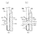
- the two contact portions of the first member 41 are provided so as to sandwich the contact portion of the second member 42 with the window glass 5 in the plane of the window glass 5. That is, before the clip 40 is attached to the window glass 5, both end portions of the first member 41 are positioned close to the second member 42 as indicated by a two-dot chain line in FIG. When the clip 40 is attached to the window glass 5, both end portions of the first member 41 are deformed in the ⁇ direction (in-vehicle direction) away from the second member 42 as shown by a solid line in FIG. In cooperation with 42, the window glass 5 is sandwiched.
- the first member 41 and the second member 42 are urged toward each other in a state where they are in contact with the window glass 5 at positions shifted in the plane of the window glass 5. That is, force is applied to the window glass 5 at different locations on the front surface 5a and the back surface 5b of the window glass 5. Further, the clip 40 clamps (holds) the lower end portion of the window glass 5 with a predetermined force or more.
- a narrow protrusion 48 is formed on the lower portion of the first member 41, and a wide protrusion 49 is formed on the upper portion of the first member 41.
- a permanent magnet 55 is disposed on the protrusion 48, and a protrusion 49 is positioned in the vicinity of the upper surface of the permanent magnet 55. That is, the permanent magnet 55 is positioned between the upper and lower protrusions 48 and 49, and the vertical magnet 55 is restricted from moving in the vertical direction by the upper and lower protrusions 48 and 49.
- the first member 41 has a curved load adjusting bend 41a.
- the first member 41 is provided with a pair of arms 45 and 46 as gripping portions for holding the permanent magnet 55.
- the pair of arms 45 and 46 and the first member 41 cooperate to grip the permanent magnet 55 when the openable window glass is not damaged, and release the grip when the window glass is broken.
- the pair of arms 45 and 46 protrude from the left and right side walls of the through hole 44 toward the center of the clip 40.
- the arms 45 and 46 are in the form of strips extending linearly, and are bent twice at the tip as shown in FIG.
- the distal ends of the arms 45 and 46 constitute magnet locking portions 45a and 46a.
- the arms 45 and 46 are made permanent by engaging the corners of the other surface of the permanent magnet 55 with the magnet locking portions 45a and 46a in a state where one surface of the permanent magnet 55 is in contact with the first member 41.
- the magnet 55 is held so as not to move in the left-right direction and the direction toward the vehicle interior. As shown by a two-dot chain line in FIG.
- the arms 45 and 46 before the clip 40 is attached to the window glass 5 are located at a location close to the second member 42.
- the arms 45 and 46 are deformed in the ⁇ direction (direction toward the vehicle interior) as shown by the solid line in FIG.
- the both sides of the magnet 55 are fixed from the inside of the vehicle.
- the first member 41 is provided with an arm 47 as an urging portion.
- the arm 47 causes the permanent magnet 55 to jump out in cooperation with the first member 41 when the openable window glass is broken. Specifically, the arm 47 protrudes from the left side wall of the through hole 44 toward the center of the clip.
- the arm 47 has a strip shape extending linearly.
- FIG. 6A the position of the arm 47 before the clip 40 is attached to the window glass 5 is represented by a two-dot chain line. Before the attachment, the distal end side of the arm 47 is located at a location separated from the second member 42.
- the arm 47 is deformed in the ⁇ direction (rear direction) as shown by a solid line in FIG. Therefore, the arm 47 presses the back surface of the permanent magnet 55 so as to urge it toward the vehicle interior side.
- the sensor unit 60 is fixed to the inner panel 3.
- the vertical direction is the X direction and the horizontal direction is the Y direction.
- the permanent magnet 55 is movable in the X direction, that is, can be dropped.
- the sensor unit 60 includes a first magnetic sensor (magnetic sensor element) 61, a second magnetic sensor (magnetic sensor element) 62, and a substrate 63.
- a first magnetic sensor 61 and a second magnetic sensor 62 are arranged on the substrate 63 so as to be separated in the vertical direction. Specifically, the magnetic sensors 61 and 62 are separated by about 4 cm.
- the first magnetic sensor 61 is disposed at the same height as the magnet 55 when the window glass 5 is fully closed.
- the first magnetic sensor 61 is arranged at a predetermined distance from the magnet 55 in the Y direction.
- the second magnetic sensor 62 is positioned below the first magnetic sensor 61. Therefore, when the permanent magnet 55 falls, the magnet 55 passes in front of the second magnetic sensor 62.
- Each magnetic sensor 61, 62 outputs a signal corresponding to the distance from the magnet 55.
- the first magnetic sensor 61 is disposed at the same height as the magnet 55, and thus has a high output voltage
- the second magnetic sensor 62 is lower than the first magnetic sensor 61. Since it is located, it has a low output voltage.
- a Hall IC can be cited.
- the magnet 55 is disposed away from the magnetic sensors 61 and 62 and can be moved relative to the magnetic sensors 61 and 62.
- the intensity of the magnetic field of the magnet 55 is detected by the magnetic sensors 61 and 62, and the position of the magnet 55 relative to the magnetic sensors 61 and 62 can be detected.
- the magnet 55 is magnetized so that the right half is an N pole and the left half is an S pole.
- the magnetic sensors 61 and 62 are arranged so that the magnetic detection surface is perpendicular to the magnetized surface (front surface) of the magnet 55.
- the magnetic flux from the N pole to the S pole in the magnet 55 is detected on the magnetic detection surfaces of the magnetic sensors 61 and 62.
- the magnetic sensors 61 and 62 are connected to the controller 70 as shown in FIG.
- the controller 70 includes an A / D converter and a microcomputer.
- the microcomputer takes in signals (output voltages Vs1, Vs2) output from the magnetic sensors 61, 62 and converted from analog data to digital data by the A / D converter.
- a signal having a high output level can be obtained in a wider range (80 mm in FIG. 13) than when the output voltages Vs1 and Vs2 of the magnetic sensors 61 and 62 in FIG. 12 are used alone.
- an alarm device 71 is connected to the controller 70.
- the operation of the clip 40 when the window glass 5 is broken will be described.
- the clip 40 is in the state shown in FIGS.
- the controller 70 detects the position of the window glass 5 from the sensor output level of FIG. 13, and sets the glass breakage detection mode when the window glass 5 is fully closed or slightly opened when the parking brake is operated.
- the clip 40 arranged at the end of the window glass 5 sandwiches the end of the window glass 5. Specifically, the window glass 5 is sandwiched between the first member 41 and the second member 42 by the elastic force of the clip 40 itself.
- the first member 41 and the second member 42 are in contact with the window glass 5 at positions shifted in the plane of the window glass 5 and urge the window glass 5 in a direction approaching each other. Further, when the window glass 5 is not broken, the pair of arms 45 and 46 and the first member 41 cooperate to hold the magnet 55. When not damaged, the magnet 55 is positioned in front of the first magnetic sensor 61 of the sensor unit 60.
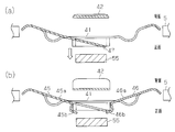
- the clip 40 crushes the end portion (lower end portion) of the window glass 5 by its clamping force as shown in FIGS. That is, the clip 40 partially pulverizes the window glass 5 made of tempered glass by its own elastic force. Specifically, since force is applied to different locations of the window glass 5 on the front surface 5a and the back surface 5b of the window glass 5, the end portion of the window glass 5 is surely attached as the window glass 5 is broken (decrease in strength). To be crushed. As a result, as shown in FIG. 10B, the arms 45 and 46 are rotated and the magnet locking portions 45a and 46a at the tips of the arms 45 and 46 are moved to engage (hold) the permanent magnet 55. To release. As a result, as shown in FIG.
- the permanent magnet 55 jumps forward and drops (is pushed out and dropped) by the arm 47 that urges the back surface of the permanent magnet 55 toward the vehicle interior side. More specifically, the permanent magnet 55 is pushed forward and dropped by the elastic force of the arm 47 against the magnetic force (attraction force) between the permanent magnet 55 and the first member 41.
- the permanent magnet 55 pops out and falls with the breakage of the window glass by the arm 47 as the urging portion.
- the sum of the output voltages of the magnetic sensors 61 and 62 shows a value equal to or higher than a predetermined threshold value. Falls, the sum of the output voltages of the magnetic sensors 61 and 62 does not show a value equal to or greater than a predetermined threshold value. Thereby, the fall of the permanent magnet 55 is detected. As a result, breakage of the window glass 5 is detected.
- tempered glass has a characteristic that if a part of it is cracked, all parts are cracked and the strength is remarkably reduced. By utilizing this feature, undetected and erroneous detection of breakage of the window glass 5 can be minimized.
- the breakage detection device 30 can detect breakage of the window glass 5.
- the breakage of the window glass can be detected when the window glass is not in the fully closed position. could not.
- the first member 41 and the second member 42 are urged in a direction approaching each other in a state in which the first member 41 and the second member 42 are in contact with the window glass 5 at positions shifted in the plane of the window glass 5. Yes.
- force is applied to the window glass 5 at different locations on the front surface 5a and the back surface 5b of the window glass 5. Therefore, it is possible to reliably detect the breakage of the window glass 5 by reliably crushing the end portion of the window glass 5 with the breakage of the window glass 5.
- the controller 70 displays the alarm device shown in FIG. 71 is activated to issue an alarm.
- the clip 40 has a first member 41 and a second member 42 which are bent and face each other.
- the first member 41 and the second member 42 are urged in a direction approaching each other by their own elasticity in a state where they are in contact with the window glass 5 at positions shifted in the plane of the window glass 5.
- the clip 40 changes the arrangement state of the permanent magnet 55 as the member to be detected with respect to the window glass 5.
- Patent Document 1 it is necessary to work on the regulator, and the reliability and quality may be reduced.
- the configuration of the present embodiment does not require work on the regulator, and the reliability. Can be of excellent quality.
- the structure is complicated, the cost is likely to increase.
- the present embodiment has a simple configuration, the breakage detection device 30 can be provided at a relatively low cost.
- the window glass 5 can freely open and close the opening of the vehicle, it is possible to detect breakage of the window glass 5 even when the window glass 5 is not in the fully closed position.
- the conventional detection device shown in FIG. 30 it is configured to detect only that the window glass 200 is displaced from the fully closed position to the closed side. Therefore, when the window glass 200 is not in the fully closed position, that is, when the window glass 200 is slightly opened for ventilation, the detection device cannot detect the breakage of the window glass 200.
- this embodiment it is possible to detect breakage of the window glass 5 even when the window glass 5 is not in the fully closed position.
- the first member 41 is provided with grip portions (arms 45, 46) as means for changing the arrangement state of the magnet 55 with respect to the window glass 5 when the window glass 5 is broken.
- the arms 45 and 46 cooperate with the first member 41 to grip the magnet 55 when the window glass 5 is not broken, and release the grip when the window glass 5 is broken. According to this configuration, the breakage of the window glass can be detected by detecting the fall of the permanent magnet 55. As a result, for example, even if the clip 40 is caught somewhere on the vehicle body or is not detached from the window glass 5 and the fall of the clip 40 is prevented, the breakage of the window glass 5 can be detected.
- the magnet 55 is held only when it is fixed to the clip 40, and when the bending of the clip 40 returns to its original shape (the shape before being attached to the window glass 5) due to glass breakage, the magnet 55 is also unfixed. Only the magnet 55 falls and is detected by the sensors 61 and 62.
- the first member 41 is provided with an urging portion (arm 47).
- the arm 47 causes the magnet 55 to jump out in cooperation with the first member 41 when the openable window glass is broken. Therefore, the breakage of the window glass can be detected by causing the magnet 55 to jump out. That is, the arm 47 is pressed by the elastic force from the side surface side of the magnet 55, and the magnet 55 is separated from the clip 40 and falls when the glass is broken.
- the member to be detected is the magnet 55. Therefore, the magnetic force can be applied to the clip 40 when the openable window glass is not broken.
- the gripping part is a pair of arms 45 and 46. Therefore, the gripping portion can be configured with a simple configuration.
- the urging unit is the arm 47. Therefore, the urging unit can be configured with a simple configuration.
- the present embodiment is not limited to the above, and may be embodied as follows, for example.
- the breakage detection device 30 is applied to the right front door in a passenger car, it may be applied to other side doors, rear doors, or an openable / closable glass roof provided on the roof.
- the sensor unit 60 includes the pair of magnetic sensors 61 and 62, the sensor unit 60 may include one magnetic sensor.
- an infrared reflecting member may be provided on the clip 40 so as to face the infrared sensor. That is, an infrared reflection mirror is provided in place of the magnet 55 in FIG. 5, an infrared sensor is provided in place of the magnetic sensor unit 60, infrared rays are emitted from the infrared sensor, and reflected light from the reflection mirror is incident and reflected. You may make it detect the fall of a mirror by the presence or absence of light. That is, the damage detection device 30 may adopt a light reflection detection method instead of a magnetic detection method.
- the clip 40 is installed at the lower end of the window glass 5, but is not limited thereto. You may install the clip 40 in the lower part in the side surface of the window glass 5, for example. In short, what is necessary is just to install in the place which is not conspicuous inside the vehicle door 1 among the edge parts of a window glass.
- the arm 47 as the urging unit may be omitted.
- the arm 47 as the urging unit may be omitted.
- the clip 40 may be attached to a fixed (fitting type) window glass instead of the openable window glass.
- the clip 40 may use another elastic material, for example, a carbon fiber material, instead of the plate spring steel plate.
- a carbon fiber material instead of the plate spring steel plate.
- the clip 80 is configured by bending a single plate spring steel plate.
- the clip 80 includes first and second members 81 and 82 and a bent portion (connecting portion) 83 that face each other.
- the first member 81 inside the vehicle has a rectangular shape extending in the left-right direction.
- the second member 82 outside the vehicle has a rectangular shape that is narrower than the first member 81.
- the bent portion 83 connects the central portion of the first member 81 in the left-right direction and the second member 82.
- the window glass 5 is disposed between the first member 81 and the second member 82, and the first member 81 and the second member 82 are urged in a direction toward the window glass 5, that is, a direction approaching each other.
- both end portions (two contact portions) in the left-right direction of the first member 81 are in contact with the first surface (surface 5a) of the window glass 5, as shown in FIG.
- the second member 82 is in contact with the second surface (back surface 5 b) of the window glass 5. Therefore, the two contact portions of the first member 81 are provided so as to sandwich the contact portion of the second member 82 with the window glass 5 in the plane of the window glass 5. That is, before the clip 80 is attached to the window glass 5, both end portions of the first member 81 are positioned close to the second member 82 as indicated by a two-dot chain line in FIG.
- both end portions of the first member 81 are deformed inward of the vehicle away from the second member 82 as shown by a solid line in FIG. 15B, and cooperate with the second member 82. And the edge part of the window glass 5 is clamped.
- the first member 81 and the second member 82 are urged in the direction of approaching each other by their own elasticity while in contact with the window glass 5 at a position shifted within the plane of the window glass 5. ing. That is, force is applied to the window glass 5 at different locations on the front surface 5a and the back surface 5b of the window glass 5.
- the clip 80 clamps (holds) the lower end of the window glass 5 with a predetermined force or more.
- Permanent magnet 100 is made of a plastic magnet (bonded magnet).
- the main body 110 of the permanent magnet 100 has a rectangular plate shape, and is magnetized so that the right half is an N pole and the left half is an S pole, as shown in FIG.
- the cylindrical portion 120 protrudes from the back surface of the main body portion 110.
- the cylindrical portion 120 passes through a through hole 81 a (see FIG. 15A) formed in the first member 81 of the clip 80, whereby the magnet 100 is rotatably supported by the clip 80.
- arc-shaped stoppers 121 and 122 are formed on the outer peripheral portion of the tip portion of the cylindrical portion 120.
- Each stopper 121, 122 is formed over 90 degrees with respect to the center of the columnar part 120, and both stoppers 121, 122 are formed at positions that are point-symmetric with respect to the center of the columnar part 120.
- a through hole 87 extending in the vertical direction is formed in the center of the first member 81 of the clip 80 in the left-right direction.
- a claw 88 extends downward from a portion of the first member 81 that defines the upper left end surface of the through hole 87.
- claw 88 is connected with the 1st member 81 in the upper end part 88a, and has comprised the strip
- the tip of the claw 88 is in contact with the side surface of the stopper 121 of the magnet 100, and the stopper 121 is urged to the left as indicated by a force F1 in FIG. Thereby, force is applied to the magnet 100 counterclockwise.
- the first member 81 is formed with a rectangular through hole 84 extending in the left-right direction.
- the first member 81 is provided with arms 85 and 86.
- the arms 85 and 86 extend linearly from the left and right side walls of the through hole 84 so as to approach each other.
- the tip of the arm 86 is in contact with the side surface of the stopper 122 of the magnet 100 (see FIG. 16C).
- the tip of the arm 85 is in contact with the side surface of the stopper 121 of the magnet 100. This prevents further rotation of the magnet 100 and keeps the magnet 100 in the normal position.
- the arms 85 and 86 and the first member 81 cooperate to hold the magnet 100 in the normal position when the window glass is not damaged, and release the holding in the normal position when the window glass is broken.
- the claw 88 urges the magnet 100 in the rotational direction by its own elasticity.
- the claw 88 constitutes means for changing the arrangement state of the magnet 100 when the window glass 5 is broken.
- the clip 80 crushes the end portion (lower end portion) of the window glass 5 by its clamping force as shown in FIG. Thereby, the first member 81 of the clip 80 is displaced to the back side as shown by a two-dot chain line in FIG. As the first member 81 of the clip 80 is displaced, the arms 85 and 86 of the clip 80 are displaced as shown by the two-dot chain line in FIG. It becomes a state. Accordingly, the magnet 100 rotates about 90 degrees counterclockwise as shown in FIG.
- the magnetic force on the magnetic detection surfaces of the magnetic sensors 61 and 62 decreases.
- the sum of the output voltages decreases to, for example, about 5.1 volts.
- the sum of the output voltages of the magnetic sensors 61 and 62 shows a value equal to or higher than a predetermined threshold value.
- the magnet 55 rotates about 90 degrees, the sum of the output voltages of the magnetic sensors 61 and 62 does not show a value equal to or greater than a predetermined threshold.
- the rotation of the permanent magnet 55 is detected.
- breakage of the window glass 5 is detected.
- the magnet 100 when the window glass 5 is not damaged, the magnet 100 has the arms 85 and 86 in contact with the side surfaces of the stoppers 121 and 122 so that the magnet 100 is fixed (held) at the normal position. Is broken, the arms 85 and 86 are disengaged from the side surfaces of the stoppers 121 and 122, and the magnet 100 is rotated by the elastic force of the claws 88 to change the magnetic force reaching the magnetic sensors 61 and 62. Breakage of the window glass 5 is detected by this change in magnetic force.
- the clip 80 rotatably supports the magnet 100 as a member to be detected and rotates the magnet 100 when the window glass 5 is broken as means for changing the arrangement state of the magnet 100 when the window glass 5 is broken. Part. Thereby, breakage of the window glass 5 can be detected by the rotation of the magnet 100.
- the rotating part is a claw 88 that urges the magnet 100 in the rotating direction by its own elasticity. Thereby, the magnet 100 can be rotated with a simple configuration.
- the third embodiment will be described with a focus on differences from the second embodiment.
- the permanent magnet 150 is rotated as in the second embodiment, but the rotation angle is 180 degrees (about 90 degrees in the second embodiment), and therefore the rotation mechanism is different.
- the window glass 5 is formed with a through hole 5c, and the through hole 5c has a circular shape.
- Permanent magnet 150 is also a plastic magnet (bonded magnet).
- the permanent magnet 150 includes a main body 160 having a rectangular plate shape. As shown in FIGS. 23C, 23 ⁇ / b> D, 24 ⁇ / b> B, and 25, a cylindrical portion 170 is provided in the center portion on the back side of the main body portion 160.
- the cylindrical portion 170 extends in a direction perpendicular to the glass surface of the window glass 5, that is, the front surface 5a and the back surface 5b.
- the cylindrical portion 170 extends through the through hole 81 a (see FIG. 23D) of the first member 81 of the clip 80 and the through hole 5 c of the window glass 5 to the back surface 5 b of the window glass 5.
- Stoppers 175 and 176 are formed at the tip of the cylindrical portion 170 on the back surface 5 b side of the window glass 5.
- the stoppers 175 and 176 are wider than the through hole 5c of the window glass 5, and prevent the magnet 150 from coming out of the through hole 5c.
- the magnet 150 as a member to be detected is rotatably supported by the clip 80 and the window glass 5.
- a through hole 82 a is formed at the location of the second member 82 of the clip 80 corresponding to the stoppers 175 and 176 of the magnet 150, and that the stoppers 175 and 176 of the magnet 150 are in contact with the second member 82 of the clip 80. Stop.
- the first member 81 of the clip 80 is formed with a rectangular through hole 180 extending in the left-right direction.
- the arms 181 and 182 extend linearly from the left and right side walls of the through-hole 180 so as to approach each other.
- the front end side of the arms 181 and 182 is urging
- the pair of arms 181 and 182 urges the magnet 150 in the direction perpendicular to the glass surface of the window glass 5 by its own elasticity.
- a spiral groove 171 is formed on the outer peripheral surface of the cylindrical portion 170 of the magnet 150.
- the spiral groove 171 is formed over 180 degrees.
- An engagement protrusion 183 is engaged with the spiral groove 171 as shown in FIG.
- the engaging protrusion 183 protrudes from the center of the bottom surface of the through hole 180 of the first member 81 of the clip 80. Then, when the back surface of the main body 160 of the magnet 150 is urged to the vehicle inner side by the arms 181 and 182 and the magnet 150 moves to the vehicle inner side, the engagement protrusion 183 engages along the spiral groove 171.
- the magnet 150 can rotate 180 degrees while maintaining.
- the engaging projection 183 and the pair of arms 181 and 182 constitute means for changing the arrangement state of the magnet 150 when the window glass 5 is broken.
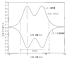
- L1 indicates a characteristic when the magnet 150 is located at the normal position as shown in FIG. 21, and L2 indicates a characteristic when the magnet 150 is rotated 180 degrees from the normal position.
- the characteristic lines L1 and L2 have a vertically inverted shape, and when the magnet 150 rotates 180 degrees from the normal position, the output voltage levels of the sensors 61 and 62 are extremely reduced.
- the operation of the clip 80 when the window glass 5 is broken will be described.
- the window glass 5 is sandwiched between the clips 80.
- the cylindrical portion 170 of the magnet 150 is inserted from the surface 5 a of the window glass 5 into the through hole 5 c in a state where the diameters of the stoppers 175 and 176 are reduced against the elastic force.
- the magnet 150 is rotated so that the engaging protrusion 183 of the clip 80 engages with the spiral groove 171 of the cylindrical portion 170 of the magnet 150.
- the stoppers 175 and 176 of the magnet 150 pass through the through hole 5c of the window glass 5 and are disposed on the back surface 5b side of the window glass 5, the diameters of the stoppers 175 and 176 are increased. As a result, the magnet 150 cannot be removed from the through hole 5 c of the window glass 5. In this state, the arms 181 and 182 apply a force toward the magnet 150 from the vehicle exterior side to the vehicle interior side.
- the sum of the output voltages of the magnetic sensors 61 and 62 shows a value equal to or higher than a predetermined threshold value. Is rotated 180 degrees, the sum of the output signals of the magnetic sensors 61 and 62 does not show a value equal to or greater than a predetermined threshold. Thereby, the rotation of the permanent magnet 55 is detected. As a result, breakage of the window glass 5 is detected. More specifically, as shown in FIG. 29, when the magnet 150 rotates 180 degrees from the normal position, the sum of the sensor outputs varies greatly.
- the rotating part that rotates the magnet 150 when the window glass 5 is broken includes an engaging protrusion 183 and a pair of arms 181 and 182.
- the engaging protrusion 183 engages with the spiral groove 171 formed on the outer peripheral surface of the columnar portion 170 extending in the direction orthogonal to the glass surface of the window glass 5 in the magnet 150 as the member to be detected.
- the pair of arms 181 and 182 urges the magnet 150 in the direction perpendicular to the glass surface of the window glass 5 by its own elasticity.
- the magnet 150 When the window glass 5 is broken, the magnet 150 is moved in a direction orthogonal to the glass surface of the window glass 5 by the pair of arms 181 and 182 with the engagement protrusion 183 engaged with the spiral groove 171. In this state, the magnet 150 rotates when the engagement protrusion 183 and the spiral groove 171 slide. Thereby, the magnet 150 can be largely rotated. That is, in the second embodiment, it is rotated about 90 degrees, but in this embodiment, it can be rotated 180 degrees. Thereby, the change of a sensor output becomes large and it can detect the failure
- the second and third embodiments may be implemented as described in the above (A) to (I) in the first embodiment.
Landscapes
- Physics & Mathematics (AREA)
- General Physics & Mathematics (AREA)
- Window Of Vehicle (AREA)
Abstract
Description
図1は、乗用車における右前ドアでの分解斜視図であり、図2は図1の右前ドアの概略正面図である。
図3に示されるように、アウタパネル2とインナパネル3との間にウィンドウガラス5がウェザーストリップ7によりシールされた状態で配置されている。また、インナパネル3の車内側にはドアトリム8が配置されている。クリップ40はウィンドウガラス5の下端部に配置され、ウィンドウガラス5を挟んでいる。
図4,5に示すように、第1部材41には、永久磁石55を保持するための把持部としての一対のアーム45,46が設けられている。この一対のアーム45,46と、第1部材41とが協働して永久磁石55を開閉式ウィンドウガラスの非破損時において把持し、破損時には把持を解除することができる。
通常時、即ち、ウィンドウガラス5の非破損時においては、クリップ40は図5,6,7に示す状態となっている。乗員が車両から離れるときにウィンドウガラス5が全閉または少し(数cmほど)開いているとする。コントローラ70は図13のセンサ出力レベルからウィンドウガラス5の位置を検出しており、パーキングブレーキが操作されている時にウィンドウガラス5が全閉または少し開いているとガラスの割れ検知モードを設定する。一方、ウィンドウガラス5の端部に配置したクリップ40がウィンドウガラス5の端部を挟持している。詳しくは、クリップ40の自身の弾性力にて第1部材41と第2部材42との間にウィンドウガラス5を挟持している。このとき、第1部材41と第2部材42とは、ウィンドウガラス5の面内でずれた位置でウィンドウガラス5に接触して、互いに接近する方向にウィンドウガラス5を付勢している。また、ウィンドウガラス5の非破損時には、一対のアーム45,46と第1部材41とが協働して磁石55を把持している。非破損時にはセンサユニット60の第1の磁気センサ61の前方に磁石55が位置している。
センサユニット60において、ウィンドウガラス5が破損される前においては磁気センサ61,62の出力電圧の和(=Vs1+Vs2)は、所定の閾値以上の値を示すが、ウィンドウガラス5の破損に伴い磁石55が落下すると、磁気センサ61,62の出力電圧の和が所定の閾値以上の値を示さなくなる。これにより、永久磁石55の落下が検知される。その結果、ウィンドウガラス5の破損が検出される。
(1)クリップ40は、折り曲げて対向させた第1部材41と第2部材42とを有する。第1部材41と第2部材42とが、ウィンドウガラス5の面内でずれた位置でウィンドウガラス5に接触する状態で、自身の弾性にて互いに接近する方向に付勢されている。ウィンドウガラス5の破損時には、クリップ40は、被検出部材としての永久磁石55のウィンドウガラス5に対する配置状態を変える。これにより、ウィンドウガラス5が完全に粉砕せずに残るような場合でも、破損検出装置30はウィンドウガラス5の破損を確実に検出することができる。
詳しくは、図30に示す従来の検出装置の場合、ウィンドウガラス200が全閉位置よりも閉止側に変位することのみを検出する構成であった。そのため、ウィンドウガラス200が全閉位置にないとき、即ち、換気のためにウィンドウガラス200を少し開けていたときには、上記検出装置はウィンドウガラス200の破損を検出することができなかった。これに対し、本実施形態においては、ウィンドウガラス5が全閉位置にないときもウィンドウガラス5の破損を検出することができる。
(6)把持部は一対のアーム45,46である。よって、簡単な構成にて把持部を構成することができる。
本実施形態は前記に限定されるものではなく、例えば、次のように具体化してもよい。
(B)駆動部としてはモータを有する構成に限らず、乗員の手動によって駆動する構成でもよい。
(D)センサユニット60は一対の磁気センサ61,62を備えていたが、1つの磁気センサを具備するものであってもよい。
(H)クリップ40は開閉式ウィンドウガラスではなく固定式(嵌め込み式)のウィンドウガラスに取り付けてもよい。
次に、第2の実施の形態を、第1の実施の形態との相違点を中心に説明する。
クリップ80をウィンドウガラス5に取り付ける際には、クリップ80の第1部材81の透孔81aに磁石100の円柱部120を差し込み、磁石100を回転させる。これにより、爪88の先端側が変形されて、磁石100に対して回転方向に沿った力F1(図15(a)参照)を加え、かつ、アーム85,86により磁石100を正規位置に保持させる。
この強度低下に伴って図19に示すようにクリップ80がその挟持力によりウィンドウガラス5の端部(下端部)を粉砕する。これにより、クリップ80の第1部材81が図16(b)において二点鎖線で示すように背面側に変位する。クリップ80の第1部材81の変位に伴いクリップ80のアーム85,86が図16(c)において二点鎖線で示すように変位してストッパ121,122の側面から外れて磁石100が回転可能な状態となる。したがって、爪88による回転力により図20に示すように、磁石100が約90度反時計回りに回転する。これによって、磁気センサ61,62の磁気検出面での磁力が低下する。例えば、図13において出力電圧の和が例えば5.1ボルト程度まで低下する。その結果、センサユニット60において、ウィンドウガラス5が破損される前においては磁気センサ61,62の出力電圧の和(=Vs1+Vs2)は、所定の閾値以上の値を示すが、ウィンドウガラス5の破損に伴い磁石55が約90度回転すると、磁気センサ61,62の出力電圧の和が所定の閾値以上の値を示さなくなる。これにより、永久磁石55の回転が検知される。その結果、ウィンドウガラス5の破損が検出される。
(1)クリップ80は、被検出部材としての磁石100を回転可能に支持するとともに、ウィンドウガラス5の破損時に磁石100の配置状態を変える手段として、ウィンドウガラス5の破損時に磁石100を回転させる回転部を有する。これにより、磁石100の回転にてウィンドウガラス5の破損を検出することができる。
次に、第3の実施の形態を、第2の実施の形態との相違点を中心に説明する。
クリップ80をウィンドウガラス5に取り付ける際には、ウィンドウガラス5をクリップ80で挟む。さらに、ストッパ175,176をその弾性力に抗して縮径させた状態で、磁石150の円柱部170をウィンドウガラス5の表面5aから貫通孔5cに差し込む。このとき、クリップ80の係合突起183が磁石150の円柱部170の螺旋溝171に係合するように磁石150を回転させる。そして、磁石150のストッパ175,176がウィンドウガラス5の貫通孔5cを貫通してウィンドウガラス5の裏面5b側に配置されると、ストッパ175,176が拡径する。これにより、磁石150はウィンドウガラス5の貫通孔5cから抜けなくなる。この状態では、アーム181,182により磁石150に対して車外側から車内側へ向かう力が加えられている。
この強度低下に伴って図27に示すようにクリップ80がその挟持力によりウィンドウガラス5の端部(下端部)を粉砕する。これにより、係合突起183が螺旋溝171に係合した状態で、一対のアーム181,182により磁石150が車内側へ移動する。この際、係合突起183と螺旋溝171とが摺動することにより磁石150が図28に示すように、180度回転する。
ウィンドウガラス5の破損時に磁石150を回転させる回転部は、係合突起183と、一対のアーム181,182とを含む。係合突起183は、被検出部材としての磁石150においてウィンドウガラス5のガラス面に直交する方向に延びる円柱部170の外周面に形成された螺旋溝171に係合する。一対のアーム181,182は、自身の弾性にて磁石150をウィンドウガラス5のガラス面に直交する方向に付勢する。ウィンドウガラス5の破損時には、係合突起183が螺旋溝171に係合した状態で、一対のアーム181,182によって磁石150がウィンドウガラス5のガラス面に直交する方向へ移動される。この状態で係合突起183と螺旋溝171とが摺動することにより、磁石150が回転する。これにより、磁石150を大きく回転させることができる。即ち、第2の実施形態では約90度回転させたが、本実施形態では180度回転させることができる。これにより、センサ出力の変化が大きくなり、より確実にウィンドウガラス5の破損を検出することができる。
Claims (11)
- 車両のウィンドウガラスに対する被検出部材の配置状態の変化に基づきウィンドウガラスの破損を検出するために用いられるウィンドウガラス破損検出用クリップであって、
互いに対向するように折り曲げられて前記ウィンドウガラスの端部を挟持する第1部材と第2部材とを備え、
前記ウィンドウガラスの非破損時においては、前記第1部材と第2部材とは、それらの間に前記ウィンドウガラスを配置した状態で同ウィンドウガラスの面内で互いにずれた位置でウィンドウガラスに接触するとともに自身の弾性にて互いに接近する方向に付勢され、
ウィンドウガラスの破損時においては、前記第1部材と第2部材とは、前記ウィンドウガラスの端部を破砕するように弾性変形し、それによってウィンドウガラスに対する前記被検出部材の配置状態を変える
破損検出用クリップ。 - 前記ウィンドウガラスは車両の開口部を開閉自在である請求項1に記載の破損検出用クリップ。
- 前記第1部材と前記第2部材とは板ばね用鋼板を折り曲げて構成される請求項1または2に記載の破損検出用クリップ。
- 前記第1部材と協働して被検出部材をウィンドウガラスの非破損時において把持し、破損時には被検出部材の配置状態を変えるべく同被検出部材の把持を解除する把持部を備える請求項1~3のいずれか1項に記載の破損検出用クリップ。
- 前記把持部は一対のアームである請求項4に記載の破損検出用クリップ。
- ウィンドウガラスの破損に伴い前記第1部材と協働して前記被検出部材を飛び出させる付勢部を更に備える請求項4に記載の破損検出用クリップ。
- 前記付勢部はアームである請求項6に記載の破損検出用クリップ。
- 前記被検出部材を回転可能に支持するとともに、前記ウィンドウガラスの破損時に被検出部材の状態を変えるべく前記被検出部材を回転させる回転部を備える請求項1~3のいずれか1項に記載の破損検出用クリップ。
- 前記回転部は、自身の弾性にて前記被検出部材を回転方向に付勢する爪である請求項8に記載の破損検出用クリップ。
- 前記被検出部材は、前記ウィンドウガラスのガラス面に直交する方向に延びる円柱部を有し、その円柱部の外周面には螺旋溝が形成され、
前記回転部は、前記螺旋溝に係合する係合突起と、
自身の弾性にて前記被検出部材を前記ウィンドウガラスのガラス面に直交する方向に付勢する一対のアームと、を含み、
前記ウィンドウガラスの破損時に、前記螺旋溝に前記係合突起が係合した状態で、前記一対のアームが前記被検出部材を前記ウィンドウガラスのガラス面に直交する方向へ移動させ、それにより前記係合突起が前記螺旋溝に沿って移動しながら前記被検出部材が回転する請求項8に記載の破損検出用クリップ。 - 前記被検出部材は磁石である請求項1~10のいずれか1項に記載の破損検出用クリップ。
Priority Applications (2)
| Application Number | Priority Date | Filing Date | Title |
|---|---|---|---|
| US12/933,098 US20110016993A1 (en) | 2008-05-22 | 2009-04-30 | Clip for detecting window glass breakage |
| CN2009801138923A CN102015383A (zh) | 2008-05-22 | 2009-04-30 | 窗玻璃破损检测用夹子 |
Applications Claiming Priority (2)
| Application Number | Priority Date | Filing Date | Title |
|---|---|---|---|
| JP2008-134328 | 2008-05-22 | ||
| JP2008134328A JP2009280084A (ja) | 2008-05-22 | 2008-05-22 | ウィンドウガラス破損検出用クリップ |
Publications (1)
| Publication Number | Publication Date |
|---|---|
| WO2009142102A1 true WO2009142102A1 (ja) | 2009-11-26 |
Family
ID=41340034
Family Applications (1)
| Application Number | Title | Priority Date | Filing Date |
|---|---|---|---|
| PCT/JP2009/058452 Ceased WO2009142102A1 (ja) | 2008-05-22 | 2009-04-30 | ウィンドウガラス破損検出用クリップ |
Country Status (5)
| Country | Link |
|---|---|
| US (1) | US20110016993A1 (ja) |
| JP (1) | JP2009280084A (ja) |
| CN (1) | CN102015383A (ja) |
| TW (1) | TW201002558A (ja) |
| WO (1) | WO2009142102A1 (ja) |
Cited By (2)
| Publication number | Priority date | Publication date | Assignee | Title |
|---|---|---|---|---|
| US20120288102A1 (en) * | 2011-05-11 | 2012-11-15 | Honeywell International Inc. | Highly Directional Glassbreak Detector |
| CN117848695A (zh) * | 2023-12-20 | 2024-04-09 | 华中科技大学 | 基于清洁作业的玻璃幕墙松动病害智能检测装置及方法 |
Families Citing this family (4)
| Publication number | Priority date | Publication date | Assignee | Title |
|---|---|---|---|---|
| CN111660997B (zh) * | 2020-06-09 | 2021-07-23 | 泉州市景江电子科技有限公司 | 一种汽车天窗智能防盗玻璃及其预警系统 |
| JP7294262B2 (ja) * | 2020-07-13 | 2023-06-20 | トヨタ自動車株式会社 | 車両 |
| US11276284B1 (en) * | 2021-04-13 | 2022-03-15 | Honeywell International Inc. | System and method for detecting events in a system |
| US12479387B1 (en) * | 2025-04-09 | 2025-11-25 | David J. Ebrahimzadeh | Automotive emergency evacuation system |
Citations (7)
| Publication number | Priority date | Publication date | Assignee | Title |
|---|---|---|---|---|
| JPS62189272U (ja) * | 1986-05-23 | 1987-12-02 | ||
| JP2009061820A (ja) * | 2007-09-04 | 2009-03-26 | Toyota Industries Corp | 自動車用窓のガラス割れ検出装置 |
| JP2009061819A (ja) * | 2007-09-04 | 2009-03-26 | Toyota Industries Corp | 開閉式ウィンドウガラスの破損検出装置 |
| WO2009041614A1 (ja) * | 2007-09-28 | 2009-04-02 | Kabushiki Kaisha Toyota Jidoshokki | 開閉式ウィンドウガラスの破損検出装置 |
| JP2009073264A (ja) * | 2007-09-19 | 2009-04-09 | Toyota Industries Corp | 開閉式ウィンドウガラスの破損検出装置 |
| JP2009083624A (ja) * | 2007-09-28 | 2009-04-23 | Toyota Industries Corp | 開閉式ウィンドウガラスの破損検出装置 |
| JP2009096448A (ja) * | 2007-09-28 | 2009-05-07 | Toyota Industries Corp | ウィンドウガラス破損検出具 |
Family Cites Families (5)
| Publication number | Priority date | Publication date | Assignee | Title |
|---|---|---|---|---|
| US4230918A (en) * | 1978-12-08 | 1980-10-28 | General Motors Corporation | Vehicle window glass breakage detector |
| GB2067804B (en) * | 1980-01-16 | 1984-06-13 | Rca Security Systems Ltd | Glass breakage detector safety mounting |
| US4901053A (en) * | 1986-02-28 | 1990-02-13 | Honda Lock Manufacturing Co., Ltd. | Anti-theft system for automotive vehicles |
| US7312705B2 (en) * | 2005-10-03 | 2007-12-25 | Honeywell International, Inc. | Security device with adjustable magnet location |
| JP4506803B2 (ja) * | 2007-09-28 | 2010-07-21 | 株式会社豊田自動織機 | 車両用窓ガラスセキュリティシステム |
-
2008
- 2008-05-22 JP JP2008134328A patent/JP2009280084A/ja not_active Withdrawn
-
2009
- 2009-04-30 US US12/933,098 patent/US20110016993A1/en not_active Abandoned
- 2009-04-30 WO PCT/JP2009/058452 patent/WO2009142102A1/ja not_active Ceased
- 2009-04-30 CN CN2009801138923A patent/CN102015383A/zh active Pending
- 2009-05-19 TW TW98116482A patent/TW201002558A/zh unknown
Patent Citations (7)
| Publication number | Priority date | Publication date | Assignee | Title |
|---|---|---|---|---|
| JPS62189272U (ja) * | 1986-05-23 | 1987-12-02 | ||
| JP2009061820A (ja) * | 2007-09-04 | 2009-03-26 | Toyota Industries Corp | 自動車用窓のガラス割れ検出装置 |
| JP2009061819A (ja) * | 2007-09-04 | 2009-03-26 | Toyota Industries Corp | 開閉式ウィンドウガラスの破損検出装置 |
| JP2009073264A (ja) * | 2007-09-19 | 2009-04-09 | Toyota Industries Corp | 開閉式ウィンドウガラスの破損検出装置 |
| WO2009041614A1 (ja) * | 2007-09-28 | 2009-04-02 | Kabushiki Kaisha Toyota Jidoshokki | 開閉式ウィンドウガラスの破損検出装置 |
| JP2009083624A (ja) * | 2007-09-28 | 2009-04-23 | Toyota Industries Corp | 開閉式ウィンドウガラスの破損検出装置 |
| JP2009096448A (ja) * | 2007-09-28 | 2009-05-07 | Toyota Industries Corp | ウィンドウガラス破損検出具 |
Cited By (3)
| Publication number | Priority date | Publication date | Assignee | Title |
|---|---|---|---|---|
| US20120288102A1 (en) * | 2011-05-11 | 2012-11-15 | Honeywell International Inc. | Highly Directional Glassbreak Detector |
| US9697707B2 (en) * | 2011-05-11 | 2017-07-04 | Honeywell International Inc. | Highly directional glassbreak detector |
| CN117848695A (zh) * | 2023-12-20 | 2024-04-09 | 华中科技大学 | 基于清洁作业的玻璃幕墙松动病害智能检测装置及方法 |
Also Published As
| Publication number | Publication date |
|---|---|
| TW201002558A (en) | 2010-01-16 |
| CN102015383A (zh) | 2011-04-13 |
| JP2009280084A (ja) | 2009-12-03 |
| US20110016993A1 (en) | 2011-01-27 |
Similar Documents
| Publication | Publication Date | Title |
|---|---|---|
| JP4506803B2 (ja) | 車両用窓ガラスセキュリティシステム | |
| JP4735631B2 (ja) | 開閉式ウィンドウガラスの破損検出装置 | |
| US20110016993A1 (en) | Clip for detecting window glass breakage | |
| JP4911069B2 (ja) | ウィンドウガラス破損検出具及び破損検出装置 | |
| JP4911068B2 (ja) | ウィンドウガラス破損検出具 | |
| EP3839182B1 (en) | A vehicle door hinge for a vehicle door, a tailgate hinge, a side door hinge and a vehicle | |
| JP2010224968A (ja) | 開閉式ウィンドウガラス破損検出装置 | |
| JP3531474B2 (ja) | 開閉式ウインドウガラスの破損検出装置 | |
| JP2011098602A (ja) | 車両用ウィンドウガラスの破損検出装置 | |
| WO2009107308A1 (ja) | ウィンドウガラス破損検出具 | |
| JP4909860B2 (ja) | 開閉式ウィンドウガラスの破損検出装置 | |
| JP5050752B2 (ja) | 開閉式ウィンドウガラスの破損検出装置 | |
| JP2011102097A (ja) | 車両用ウィンドウガラスの破損検出装置 | |
| JP5141619B2 (ja) | ウィンドウガラス破損検出具 | |
| JPS62296112A (ja) | 光透過量調整装置 | |
| JP4871817B2 (ja) | 開閉式ウィンドウガラスの破損検出装置 | |
| WO2010067747A1 (ja) | 開閉式ウィンドウガラス破損検出装置 | |
| JP2010060469A (ja) | 距離計測装置および開閉式ウィンドウガラスの破損検出装置 | |
| JP2009092386A (ja) | 位置検出装置 | |
| JP2010224969A (ja) | 車両用ウィンドウガラス破損検出装置 | |
| JP2010139272A (ja) | 開閉式ウィンドウガラス破損検出装置 | |
| JP2011165055A (ja) | 車両用ウィンドウガラスの破損検出装置 | |
| JP2011098603A (ja) | 開閉式ウィンドウガラスの破損検出装置 | |
| KR20070061657A (ko) | 차량 윈도우 자동 닫힘 장치 |
Legal Events
| Date | Code | Title | Description |
|---|---|---|---|
| WWE | Wipo information: entry into national phase |
Ref document number: 200980113892.3 Country of ref document: CN |
|
| 121 | Ep: the epo has been informed by wipo that ep was designated in this application |
Ref document number: 09750464 Country of ref document: EP Kind code of ref document: A1 |
|
| WWE | Wipo information: entry into national phase |
Ref document number: 12933098 Country of ref document: US |
|
| NENP | Non-entry into the national phase |
Ref country code: DE |
|
| 122 | Ep: pct application non-entry in european phase |
Ref document number: 09750464 Country of ref document: EP Kind code of ref document: A1 |