WO2009141956A1 - 流体機械および冷凍サイクル装置 - Google Patents
流体機械および冷凍サイクル装置 Download PDFInfo
- Publication number
- WO2009141956A1 WO2009141956A1 PCT/JP2009/001706 JP2009001706W WO2009141956A1 WO 2009141956 A1 WO2009141956 A1 WO 2009141956A1 JP 2009001706 W JP2009001706 W JP 2009001706W WO 2009141956 A1 WO2009141956 A1 WO 2009141956A1
- Authority
- WO
- WIPO (PCT)
- Prior art keywords
- oil
- compression mechanism
- sealed container
- working fluid
- compressor
- Prior art date
Links
- 239000012530 fluid Substances 0.000 title claims abstract description 119
- 238000005057 refrigeration Methods 0.000 title abstract description 36
- 230000007246 mechanism Effects 0.000 claims description 165
- 230000006835 compression Effects 0.000 claims description 105
- 238000007906 compression Methods 0.000 claims description 105
- 230000001629 suppression Effects 0.000 claims description 57
- CURLTUGMZLYLDI-UHFFFAOYSA-N Carbon dioxide Chemical compound O=C=O CURLTUGMZLYLDI-UHFFFAOYSA-N 0.000 claims description 6
- 230000000452 restraining effect Effects 0.000 claims description 4
- 229910002092 carbon dioxide Inorganic materials 0.000 claims description 3
- 239000001569 carbon dioxide Substances 0.000 claims description 3
- 230000001105 regulatory effect Effects 0.000 claims 1
- 238000005461 lubrication Methods 0.000 abstract description 4
- 239000003507 refrigerant Substances 0.000 description 21
- 230000002093 peripheral effect Effects 0.000 description 19
- 238000010586 diagram Methods 0.000 description 11
- 230000000694 effects Effects 0.000 description 9
- 238000005192 partition Methods 0.000 description 8
- 230000008859 change Effects 0.000 description 5
- 238000006073 displacement reaction Methods 0.000 description 5
- 238000011084 recovery Methods 0.000 description 5
- 230000007423 decrease Effects 0.000 description 4
- 238000007789 sealing Methods 0.000 description 4
- 230000005484 gravity Effects 0.000 description 3
- 125000006850 spacer group Chemical group 0.000 description 3
- 238000003466 welding Methods 0.000 description 3
- 239000000470 constituent Substances 0.000 description 2
- 230000003247 decreasing effect Effects 0.000 description 2
- 238000009826 distribution Methods 0.000 description 2
- 238000009413 insulation Methods 0.000 description 2
- 238000000034 method Methods 0.000 description 2
- 238000012546 transfer Methods 0.000 description 2
- 235000014676 Phragmites communis Nutrition 0.000 description 1
- 239000006096 absorbing agent Substances 0.000 description 1
- 230000004308 accommodation Effects 0.000 description 1
- KYKAJFCTULSVSH-UHFFFAOYSA-N chloro(fluoro)methane Chemical compound F[C]Cl KYKAJFCTULSVSH-UHFFFAOYSA-N 0.000 description 1
- 238000004891 communication Methods 0.000 description 1
- 238000001816 cooling Methods 0.000 description 1
- NBVXSUQYWXRMNV-UHFFFAOYSA-N fluoromethane Chemical compound FC NBVXSUQYWXRMNV-UHFFFAOYSA-N 0.000 description 1
- 238000010438 heat treatment Methods 0.000 description 1
- 230000005764 inhibitory process Effects 0.000 description 1
- 239000011810 insulating material Substances 0.000 description 1
- 238000007562 laser obscuration time method Methods 0.000 description 1
- 230000001050 lubricating effect Effects 0.000 description 1
- 230000014759 maintenance of location Effects 0.000 description 1
- 238000004519 manufacturing process Methods 0.000 description 1
- 230000004048 modification Effects 0.000 description 1
- 238000012986 modification Methods 0.000 description 1
- 230000000149 penetrating effect Effects 0.000 description 1
- 230000008569 process Effects 0.000 description 1
- 238000005086 pumping Methods 0.000 description 1
- 230000000717 retained effect Effects 0.000 description 1
- 238000000926 separation method Methods 0.000 description 1
- 238000002791 soaking Methods 0.000 description 1
- 238000003756 stirring Methods 0.000 description 1
- 238000013517 stratification Methods 0.000 description 1
- 230000007704 transition Effects 0.000 description 1
- XLYOFNOQVPJJNP-UHFFFAOYSA-N water Substances O XLYOFNOQVPJJNP-UHFFFAOYSA-N 0.000 description 1
Images


Classifications
-
- F—MECHANICAL ENGINEERING; LIGHTING; HEATING; WEAPONS; BLASTING
- F25—REFRIGERATION OR COOLING; COMBINED HEATING AND REFRIGERATION SYSTEMS; HEAT PUMP SYSTEMS; MANUFACTURE OR STORAGE OF ICE; LIQUEFACTION SOLIDIFICATION OF GASES
- F25B—REFRIGERATION MACHINES, PLANTS OR SYSTEMS; COMBINED HEATING AND REFRIGERATION SYSTEMS; HEAT PUMP SYSTEMS
- F25B31/00—Compressor arrangements
- F25B31/002—Lubrication
- F25B31/004—Lubrication oil recirculating arrangements
-
- F—MECHANICAL ENGINEERING; LIGHTING; HEATING; WEAPONS; BLASTING
- F04—POSITIVE - DISPLACEMENT MACHINES FOR LIQUIDS; PUMPS FOR LIQUIDS OR ELASTIC FLUIDS
- F04B—POSITIVE-DISPLACEMENT MACHINES FOR LIQUIDS; PUMPS
- F04B39/00—Component parts, details, or accessories, of pumps or pumping systems specially adapted for elastic fluids, not otherwise provided for in, or of interest apart from, groups F04B25/00 - F04B37/00
- F04B39/02—Lubrication
- F04B39/0207—Lubrication with lubrication control systems
-
- F—MECHANICAL ENGINEERING; LIGHTING; HEATING; WEAPONS; BLASTING
- F04—POSITIVE - DISPLACEMENT MACHINES FOR LIQUIDS; PUMPS FOR LIQUIDS OR ELASTIC FLUIDS
- F04B—POSITIVE-DISPLACEMENT MACHINES FOR LIQUIDS; PUMPS
- F04B39/00—Component parts, details, or accessories, of pumps or pumping systems specially adapted for elastic fluids, not otherwise provided for in, or of interest apart from, groups F04B25/00 - F04B37/00
- F04B39/02—Lubrication
- F04B39/0223—Lubrication characterised by the compressor type
- F04B39/023—Hermetic compressors
-
- F—MECHANICAL ENGINEERING; LIGHTING; HEATING; WEAPONS; BLASTING
- F04—POSITIVE - DISPLACEMENT MACHINES FOR LIQUIDS; PUMPS FOR LIQUIDS OR ELASTIC FLUIDS
- F04B—POSITIVE-DISPLACEMENT MACHINES FOR LIQUIDS; PUMPS
- F04B41/00—Pumping installations or systems specially adapted for elastic fluids
- F04B41/06—Combinations of two or more pumps
-
- F—MECHANICAL ENGINEERING; LIGHTING; HEATING; WEAPONS; BLASTING
- F04—POSITIVE - DISPLACEMENT MACHINES FOR LIQUIDS; PUMPS FOR LIQUIDS OR ELASTIC FLUIDS
- F04C—ROTARY-PISTON, OR OSCILLATING-PISTON, POSITIVE-DISPLACEMENT MACHINES FOR LIQUIDS; ROTARY-PISTON, OR OSCILLATING-PISTON, POSITIVE-DISPLACEMENT PUMPS
- F04C18/00—Rotary-piston pumps specially adapted for elastic fluids
- F04C18/02—Rotary-piston pumps specially adapted for elastic fluids of arcuate-engagement type, i.e. with circular translatory movement of co-operating members, each member having the same number of teeth or tooth-equivalents
- F04C18/0207—Rotary-piston pumps specially adapted for elastic fluids of arcuate-engagement type, i.e. with circular translatory movement of co-operating members, each member having the same number of teeth or tooth-equivalents both members having co-operating elements in spiral form
- F04C18/0215—Rotary-piston pumps specially adapted for elastic fluids of arcuate-engagement type, i.e. with circular translatory movement of co-operating members, each member having the same number of teeth or tooth-equivalents both members having co-operating elements in spiral form where only one member is moving
-
- F—MECHANICAL ENGINEERING; LIGHTING; HEATING; WEAPONS; BLASTING
- F04—POSITIVE - DISPLACEMENT MACHINES FOR LIQUIDS; PUMPS FOR LIQUIDS OR ELASTIC FLUIDS
- F04C—ROTARY-PISTON, OR OSCILLATING-PISTON, POSITIVE-DISPLACEMENT MACHINES FOR LIQUIDS; ROTARY-PISTON, OR OSCILLATING-PISTON, POSITIVE-DISPLACEMENT PUMPS
- F04C18/00—Rotary-piston pumps specially adapted for elastic fluids
- F04C18/30—Rotary-piston pumps specially adapted for elastic fluids having the characteristics covered by two or more of groups F04C18/02, F04C18/08, F04C18/22, F04C18/24, F04C18/48, or having the characteristics covered by one of these groups together with some other type of movement between co-operating members
- F04C18/34—Rotary-piston pumps specially adapted for elastic fluids having the characteristics covered by two or more of groups F04C18/02, F04C18/08, F04C18/22, F04C18/24, F04C18/48, or having the characteristics covered by one of these groups together with some other type of movement between co-operating members having the movement defined in group F04C18/08 or F04C18/22 and relative reciprocation between the co-operating members
- F04C18/356—Rotary-piston pumps specially adapted for elastic fluids having the characteristics covered by two or more of groups F04C18/02, F04C18/08, F04C18/22, F04C18/24, F04C18/48, or having the characteristics covered by one of these groups together with some other type of movement between co-operating members having the movement defined in group F04C18/08 or F04C18/22 and relative reciprocation between the co-operating members with vanes reciprocating with respect to the outer member
-
- F—MECHANICAL ENGINEERING; LIGHTING; HEATING; WEAPONS; BLASTING
- F04—POSITIVE - DISPLACEMENT MACHINES FOR LIQUIDS; PUMPS FOR LIQUIDS OR ELASTIC FLUIDS
- F04C—ROTARY-PISTON, OR OSCILLATING-PISTON, POSITIVE-DISPLACEMENT MACHINES FOR LIQUIDS; ROTARY-PISTON, OR OSCILLATING-PISTON, POSITIVE-DISPLACEMENT PUMPS
- F04C23/00—Combinations of two or more pumps, each being of rotary-piston or oscillating-piston type, specially adapted for elastic fluids; Pumping installations specially adapted for elastic fluids; Multi-stage pumps specially adapted for elastic fluids
- F04C23/005—Combinations of two or more pumps, each being of rotary-piston or oscillating-piston type, specially adapted for elastic fluids; Pumping installations specially adapted for elastic fluids; Multi-stage pumps specially adapted for elastic fluids of dissimilar working principle
- F04C23/006—Combinations of two or more pumps, each being of rotary-piston or oscillating-piston type, specially adapted for elastic fluids; Pumping installations specially adapted for elastic fluids; Multi-stage pumps specially adapted for elastic fluids of dissimilar working principle having complementary function
-
- F—MECHANICAL ENGINEERING; LIGHTING; HEATING; WEAPONS; BLASTING
- F25—REFRIGERATION OR COOLING; COMBINED HEATING AND REFRIGERATION SYSTEMS; HEAT PUMP SYSTEMS; MANUFACTURE OR STORAGE OF ICE; LIQUEFACTION SOLIDIFICATION OF GASES
- F25B—REFRIGERATION MACHINES, PLANTS OR SYSTEMS; COMBINED HEATING AND REFRIGERATION SYSTEMS; HEAT PUMP SYSTEMS
- F25B1/00—Compression machines, plants or systems with non-reversible cycle
- F25B1/04—Compression machines, plants or systems with non-reversible cycle with compressor of rotary type
-
- F—MECHANICAL ENGINEERING; LIGHTING; HEATING; WEAPONS; BLASTING
- F25—REFRIGERATION OR COOLING; COMBINED HEATING AND REFRIGERATION SYSTEMS; HEAT PUMP SYSTEMS; MANUFACTURE OR STORAGE OF ICE; LIQUEFACTION SOLIDIFICATION OF GASES
- F25B—REFRIGERATION MACHINES, PLANTS OR SYSTEMS; COMBINED HEATING AND REFRIGERATION SYSTEMS; HEAT PUMP SYSTEMS
- F25B2309/00—Gas cycle refrigeration machines
- F25B2309/06—Compression machines, plants or systems characterised by the refrigerant being carbon dioxide
-
- F—MECHANICAL ENGINEERING; LIGHTING; HEATING; WEAPONS; BLASTING
- F25—REFRIGERATION OR COOLING; COMBINED HEATING AND REFRIGERATION SYSTEMS; HEAT PUMP SYSTEMS; MANUFACTURE OR STORAGE OF ICE; LIQUEFACTION SOLIDIFICATION OF GASES
- F25B—REFRIGERATION MACHINES, PLANTS OR SYSTEMS; COMBINED HEATING AND REFRIGERATION SYSTEMS; HEAT PUMP SYSTEMS
- F25B2400/00—General features or devices for refrigeration machines, plants or systems, combined heating and refrigeration systems or heat-pump systems, i.e. not limited to a particular subgroup of F25B
- F25B2400/07—Details of compressors or related parts
- F25B2400/075—Details of compressors or related parts with parallel compressors
-
- F—MECHANICAL ENGINEERING; LIGHTING; HEATING; WEAPONS; BLASTING
- F25—REFRIGERATION OR COOLING; COMBINED HEATING AND REFRIGERATION SYSTEMS; HEAT PUMP SYSTEMS; MANUFACTURE OR STORAGE OF ICE; LIQUEFACTION SOLIDIFICATION OF GASES
- F25B—REFRIGERATION MACHINES, PLANTS OR SYSTEMS; COMBINED HEATING AND REFRIGERATION SYSTEMS; HEAT PUMP SYSTEMS
- F25B2400/00—General features or devices for refrigeration machines, plants or systems, combined heating and refrigeration systems or heat-pump systems, i.e. not limited to a particular subgroup of F25B
- F25B2400/14—Power generation using energy from the expansion of the refrigerant
-
- F—MECHANICAL ENGINEERING; LIGHTING; HEATING; WEAPONS; BLASTING
- F25—REFRIGERATION OR COOLING; COMBINED HEATING AND REFRIGERATION SYSTEMS; HEAT PUMP SYSTEMS; MANUFACTURE OR STORAGE OF ICE; LIQUEFACTION SOLIDIFICATION OF GASES
- F25B—REFRIGERATION MACHINES, PLANTS OR SYSTEMS; COMBINED HEATING AND REFRIGERATION SYSTEMS; HEAT PUMP SYSTEMS
- F25B2500/00—Problems to be solved
- F25B2500/01—Geometry problems, e.g. for reducing size
-
- F—MECHANICAL ENGINEERING; LIGHTING; HEATING; WEAPONS; BLASTING
- F25—REFRIGERATION OR COOLING; COMBINED HEATING AND REFRIGERATION SYSTEMS; HEAT PUMP SYSTEMS; MANUFACTURE OR STORAGE OF ICE; LIQUEFACTION SOLIDIFICATION OF GASES
- F25B—REFRIGERATION MACHINES, PLANTS OR SYSTEMS; COMBINED HEATING AND REFRIGERATION SYSTEMS; HEAT PUMP SYSTEMS
- F25B2500/00—Problems to be solved
- F25B2500/16—Lubrication
Definitions
- the present invention relates to a fluid machine used for a water heater, an air conditioner, and the like, and a refrigeration cycle apparatus using the fluid machine.
- a power recovery type refrigeration cycle apparatus has been proposed in which the power required to drive the compression mechanism is reduced by the recovery amount.
- an expander-integrated compressor in which an electric motor, a compression mechanism, and an expansion mechanism are connected by a shaft is used.
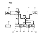
- FIG. 8 is a configuration diagram showing the refrigeration cycle apparatus described in Patent Document 1.
- the refrigeration cycle apparatus using the expander-integrated compressor 220 and the second compressor 230 includes a refrigerant circuit 210 and a controller 250 as control means.
- a first compression mechanism 221 of the expander-integrated compressor 220 and a second compression mechanism 231 of the second compressor 230 are disposed between the indoor heat exchanger 211 and the outdoor heat exchanger 212. They are arranged in parallel.
- the first compression mechanism 221 is connected to the electric motor 222 and the expansion mechanism 223 via a shaft
- the second compression mechanism 231 is connected to the electric motor 232 via a shaft.
- the controller 250 controls the second compressor 230 so that the high pressure of the refrigeration cycle becomes a predetermined target value. Specifically, if the measured value of the high pressure Ph is higher than the target value, the controller 250 reduces the discharge rate of the second compression mechanism 231 by reducing the rotational speed of the electric motor 232, and conversely, measures the high pressure Ph. If the value is lower than the target value, the rotational speed of the electric motor 232 is increased and the discharge amount of the second compression mechanism 231 is increased.
- the second compression mechanism 231 can be driven to compensate for the insufficient displacement, and the refrigeration cycle apparatus can keep the COP high. Can continue driving.
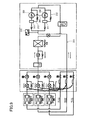
- Patent Document 2 discloses a refrigeration cycle apparatus as shown in FIG.
- This refrigeration cycle apparatus includes a refrigerant circuit 310 in which two compressors 320 and 330 are arranged in parallel.
- oil used for lubrication and sealing of the sliding portion of the compression mechanism is stored.
- the refrigeration cycle apparatus disclosed in Patent Document 2 employs a structure that balances the oil holding amounts of both compressors 320 and 330.
- an oil separator 311 is provided in the refrigerant discharge side piping of the compressors 320 and 330, and the oil bypass pipe 312 extends from the oil separator 311 to the refrigerant suction side piping of the compressors 320 and 330.
- the lower portions of the compressors 320 and 330 are connected to each other by an oil equalizing pipe 350, and oil can be distributed between the compressors 320 and 330 through the oil equalizing pipe 350.
- a pressure sensor 315 is provided in the high-pressure side pipe of the refrigeration cycle.
- the operating frequency of one compressor 320 is first stepped up by a certain value, and the operating frequency of the other compressor 330 is lowered so that the detected pressure Pd of the pressure sensor 315 does not change until the set time ta elapses. .
- the operating frequency of one compressor 320 is stepped down by a certain value, and the other compressor is kept so that the detected pressure Pd of the pressure sensor 315 does not change until the set time ta elapses.
- Increase 330 operating frequency is increased.
- the set time ta elapses again, the operating frequencies of the compressors 320 and 330 are restored.
- the above-described step-up and step-down oil equalization operations are repeated.
- the compressors 320 and 330 are connected to each other by the oil equalizing pipe 350, and when the two compressors 320 and 330 are operated, the operation frequency of the compressors 320 and 330 is alternately increased and decreased, The oil of 330 is efficiently circulated through the oil equalizing pipe 350, and the balance of the oil holding amounts of both the compressors 320 and 330 is maintained.
- the expander-integrated compressor 230 and the second compressor 230 are connected to each other by an oil equalizing pipe. Even if the oil leveling operation as described in FIG. 2 is performed to balance the oil holding amount, the first compressor 220 and the second compressor 230 are asymmetrical fluid machines, so that the oil leveling effect is sufficient. Cannot be obtained.
- the expander-integrated compressor 220 includes the expansion mechanism 223 in addition to the first compression mechanism 221 in comparison with the second compressor 230 in which the rotary machine is a single second compression mechanism 231. Large amount.
- the present invention has been made in view of such points, and an object of the present invention is to provide a highly reliable fluid machine including an expansion mechanism and a plurality of compression mechanisms.
- the present invention provides a first sealed container in which a first oil reservoir is formed at a bottom, and an internal space above the first oil reservoir is filled with a working fluid, and the first sealed container
- the first electric motor arranged in the inside, the first compression mechanism arranged in the first sealed container for compressing the working fluid, and the expanding working fluid arranged in the first sealed container for power.
- a first oil pump that supplies one or both of the first compression mechanism and the expansion mechanism through a first oil supply passage that extends upward from the first oil reservoir provided; and a space in the first sealed container. Partition up and down A first suppression member arranged to prevent the oil in the first oil reservoir from flowing along with the flow of the working fluid in the first sealed container, and a second oil reservoir is formed at the bottom, A second sealed container in which the internal space above the second oil reservoir is filled with a working fluid, a second electric motor disposed in the second sealed container, and an operation disposed in the second sealed container A second compression mechanism for compressing a fluid, wherein the first closed container and the second closed container are connected to each other by piping to be connected in parallel with the first compression mechanism in a working fluid circuit.
- a second compression mechanism a second shaft connecting the second electric motor and the second compression mechanism, and a second oil provided in the second shaft by sucking oil from the second oil reservoir through a second oil suction port.
- the second through the oil supply path A second oil pump for supplying to the compression mechanism, and an oil in the second oil reservoir that is arranged so as to partition the space in the second sealed container up and down with the flow of the working fluid in the second sealed container
- a second restraining member that restrains the fluid from flowing, and a volume of a first effective oil space from the first restraining member to the first oil suction port in the first sealed container is the second sealed
- a fluid machine that is set to be larger than a volume of a second effective oil space from the second suppressing member to the second oil suction port in the container.
- the present invention includes a working fluid circuit in which the fluid machine is incorporated, and the first compression mechanism and the second compression mechanism are arranged in parallel in the working fluid circuit.
- the fluid circuit is provided with a refrigeration cycle device filled with carbon dioxide as a working fluid.
- the volume of the first effective oil space is set larger than the volume of the second effective oil space, and a sufficient amount of oil is secured above the first oil suction port. become. For this reason, even if both compressors are operated and the oil level of the first oil reservoir is lowered, the oil in the first oil reservoir can be sufficiently supplied to the compression mechanism or the expansion mechanism by the first oil pump. . Therefore, according to the present invention, a highly reliable fluid machine can be realized.
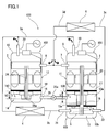
- FIG. 1 is a schematic configuration diagram showing a refrigeration cycle apparatus using a fluid machine according to a first embodiment of the present invention.
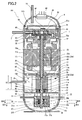
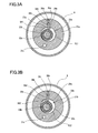
- Longitudinal sectional view of the first compressor of the first embodiment 3A is a cross-sectional view taken along line IIIA-IIIA
- FIG. 3B is a cross-sectional view taken along line IIIB-IIIB in FIG.
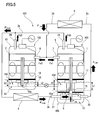
- Longitudinal sectional view of the second compressor of the first embodiment Oil flow state diagram immediately after startup of the refrigeration cycle apparatus shown in FIG. 6A is a change diagram of the oil flow rate as the operation time elapses in the fluid machine
- FIG. 6B is a change diagram of the oil surface height as the operation time elapses in the fluid machine.
- Configuration diagram showing a conventional refrigeration cycle apparatus
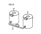
- Configuration diagram showing another conventional refrigeration cycle apparatus The perspective view which shows the compressor and the oil equalizing pipe in the refrigeration cycle apparatus shown in FIG.
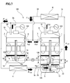
- FIG. 1 shows a refrigeration cycle apparatus using a fluid machine 105 according to a first embodiment of the present invention.
- This refrigeration cycle apparatus includes a refrigerant circuit (working fluid circuit) 103 in which a fluid machine 105 is incorporated.
- the refrigerant circuit 103 includes a first compressor (expander-integrated compressor) 101, a second compressor 102, a radiator 4, an evaporator 6, and first to fourth pipes (refrigerant pipes) that connect these devices. 3a to 3d.
- the first compressor 101 and the second compressor 102 are connected to each other by an oil equalizing pipe 25, and the fluid machine 105 is configured by the first compressor 101, the second compressor 102, and the oil equalizing pipe 25. It is configured.
- the first discharge pipe 19 of the first compressor 101 and the second discharge pipe 20 of the second compressor 102 radiate heat through the first pipe 3a in which two branch pipes become one main pipe.
- the radiator 4 is connected to the expansion side suction pipe 21 of the first compressor 101 via the second pipe 3b.
- the expansion side discharge pipe 22 of the first compressor 101 is connected to the evaporator 6 via the third pipe 3c.
- the evaporator 6 is connected to the first suction pipe 7 of the first compressor 101 and the second suction pipe 8 of the second compressor 102 via a fourth pipe 3d in which one main pipe becomes two branch pipes. Has been.
- the 1st compressor 101 has the 1st airtight container 9 which accommodates the 1st compression mechanism 1, the 1st electric motor 11, and the expansion mechanism 5 which were mutually connected by the 1st shaft 23.
- the second compression mechanism 102 includes a second sealed container 10 that houses the second compression mechanism 2 and the second electric motor 12 that are connected to each other by the second shaft 24.
- the working fluid (refrigerant) compressed by the first compression mechanism 1 and the working fluid compressed by the second compression mechanism 2 pass through the first discharge pipe 19 and the second discharge pipe 20, respectively, 2 It is discharged out of the sealed container 10.
- first sealed container 9 and the second sealed container 10 are connected to each other by the first pipe 3 a and the fourth pipe 3 d, so that the first compression mechanism 1 and the second compression mechanism 2 are in the refrigerant circuit 103. They are arranged in parallel. In other words, the first compression mechanism 1 is connected in parallel with the second compression mechanism 2 in the refrigerant circuit 103.
- the refrigerant circuit 103 is filled with a working fluid that becomes a supercritical state in a high-pressure portion (a portion from the first compression mechanism 1 and the second compression mechanism 2 to the expansion mechanism 5 through the radiator 4).
- the refrigerant circuit 103 is filled with carbon dioxide (CO 2 ) as such a working fluid.
- CO 2 carbon dioxide
- the type of working fluid is not particularly limited.
- the working fluid may be a working fluid that does not enter a supercritical state during operation (for example, a fluorocarbon working fluid).
- the refrigerant circuit 103 in which the fluid machine of the present invention is incorporated is not limited to the refrigerant circuit that allows the working fluid to flow only in one direction.
- the fluid machine of the present invention may be provided in a refrigerant circuit capable of changing the flow direction of the working fluid, for example, provided in a refrigerant circuit capable of switching between heating operation and cooling operation by having a four-way valve or the like. It may be done.
- the first sealed container 9 has a cylindrical shape extending in the vertical direction with the upper end and the lower end closed.
- a first oil reservoir 13 is formed at the bottom of the first sealed container 9 by collecting oil, and the internal space above the first oil reservoir 13 of the first sealed container 9 is the first compression mechanism 1. It is filled with the working fluid discharged from.
- the expansion mechanism 5 is disposed at a lower position in the first sealed container 9 and is immersed in the first oil reservoir 13, and the first compression mechanism 1 is disposed at an upper position in the first sealed container 9.
- the first shaft 23 extends in the vertical direction across the first compression mechanism 1 and the expansion mechanism 5.
- the 1st airtight container 9 between the 1st compression mechanism 1 and the expansion mechanism 5, the 1st electric motor 11, the 1st oil flow suppression board (1st suppression member) 17, the 1st oil pump 15, And the heat insulation member 37 is arrange
- a first oil supply path 23e is formed inside the first shaft 23 and extends upward from the first oil reservoir 13 and guides oil from the first oil pump 15 to the first compression mechanism 1. More specifically, the first shaft 23 is composed of an upper shaft 23 a and a lower shaft 23 b, and these shafts 23 a and 23 b are mutually below by the connecting member 26 at a position slightly lower than the first oil flow suppression plate 17. It is connected.
- the first oil supply path 23e includes an upper oil path 23c that penetrates the upper shaft 23a in the axial direction, and a lower oil path that extends downward from the upper end surface of the lower shaft 23b and opens to the side surface of the lower shaft 23b. 23d. Further, an expansion mechanism side oil supply passage 23f that guides oil from the lower end surface of the lower shaft 23b to each sliding portion of the expansion mechanism 5 is formed inside the lower shaft 23b.
- the compression mechanism 1 is fixed to the inner peripheral surface of the first sealed container 9 by welding or the like.
- the compression mechanism 1 is of a scroll type.
- the type or the like of the compression mechanism 1 is not limited at all, and for example, a rotary compressor or the like can be used.
- the compression mechanism 1 includes a fixed scroll 51, a movable scroll 52 facing the fixed scroll 51 in the axial direction, and a bearing member 53 that supports the upper portion of the upper shaft 23a.
- the fixed scroll 51 and the movable scroll 52 are formed with wraps 51a and 52a that mesh with each other, and a spiral compression chamber 58 is defined between these wraps 51a and 52a.
- a discharge hole 51 b that is opened and closed by a reed valve 64 is provided at the center of the fixed scroll 51.
- An Oldham ring 60 that prevents the rotation of the movable scroll 52 is disposed below the movable scroll 52.
- An eccentric portion is formed at the upper end portion of the upper shaft 23a, and the movable scroll 52 is fitted to the eccentric portion. Therefore, the movable scroll 52 turns in a state of being eccentric from the axis of the upper shaft 23a.
- the movable scroll 52 is provided with an oil distribution path 52b that guides oil supplied from the first oil supply path 23e to each sliding portion
- a cover 62 is provided above the fixed scroll 51.
- a discharge path 61 is formed at a position covered with the cover 62 so as to penetrate up and down.
- the fixed scroll 51 and the bearing 53 are formed with flow passages 63 penetrating up and down at positions outside the cover 62.
- the first suction pipe 7 penetrates the side of the first sealed container 9 and is connected to the fixed scroll 51. Thereby, the first suction pipe 7 is connected to the suction side of the first compression mechanism 1.
- the first discharge pipe 19 passes through the upper part of the first sealed container 9, and the lower end of the first discharge pipe 19 opens into a space above the first compression mechanism 1 in the first sealed container 9. .
- the first electric motor 11 is composed of a rotor 11a fixed to the middle portion of the upper shaft 23a and a stator 11b arranged on the outer peripheral side of the rotor 11a.
- the stator 11 b is fixed to the inner peripheral surface of the first sealed container 9.
- the stator 11b is connected to a terminal 66 through a motor wiring 65.
- the first compression mechanism 1 is driven by rotating the upper shaft 23 a by the first electric motor 11.
- the first oil flow suppression plate 17 partitions the space in the first hermetic container 9 vertically, that is, the upper space 9a and the lower space 9b, at a position slightly above the first oil reservoir 13 (when operation is stopped).
- the first oil flow suppression plate 17 has a disk shape that is flat in the vertical direction and has a diameter substantially the same as the inner diameter of the first sealed container 9, and the peripheral portion is the first sealed container. It is fixed to the inner peripheral surface of 9 by welding or the like.
- the first oil flow suppression plate 17 prevents the oil in the first oil reservoir 13 from flowing along with the flow of the working fluid in the first sealed container 9.
- the working fluid that fills the upper space 9 a forms a swirling flow by the rotation of the rotor 11 a of the first electric motor 11, and before the swirling flow reaches the oil surface S 1 of the first oil reservoir 13, 1
- the oil flow suppression plate 17 is blocked.
- the oil pump 15, the heat insulating member 37, the expansion mechanism 5, and the like are fixed to the first sealed container 9 via the first oil flow suppression plate 17.
- a heat-insulating member 37 or an upper bearing member 29 (to be described later) of the expansion mechanism 5 is fixed to the first sealed container 9, and the oil pump 15 and the first oil flow suppression plate 17 are connected to the first sealed container 9 through this.
- the first oil flow suppression plate 17 has a disk shape having a diameter slightly smaller than the inner diameter of the first closed container 9, and an oil return path to be described next is provided on the first oil flow suppression plate 17. You may be comprised by the clearance gap between a peripheral part and the internal peripheral surface of the 1st airtight container 9. FIG. However, if the first oil flow suppression plate 17 is configured to be directly fixed to the first airtight container 9, the assembly of the device becomes easy.
- a plurality of through holes 17a are provided in the peripheral edge portion of the first oil flow suppression plate 17, and an oil return path for flowing oil from the upper space 9a to the lower space 9b is configured by these through holes 17a. Yes.
- the number and shape of the through holes 17a can be selected as appropriate.
- a through hole 17 b is provided at the center of the first oil flow suppression plate 17.
- the bearing member 42 which supports the lower part of the upper side shaft 23a is attached to the lower surface of the 1st oil flow suppression board 17 so that it may be fitted by the through-hole 17b.
- a housing chamber 43 for housing the connecting member 26 is provided on the lower surface of the bearing member 42. Further, an intermediate member 41 is arranged below the bearing member 42 and extends in the vertical direction with a predetermined cross-sectional shape, and the lower shaft 23b passes through the center thereof. The intermediate member 41 closes the housing chamber 43. Has been.
- the first oil pump 15 is sandwiched between the intermediate member 41 and the heat insulating member 37.
- the first oil pump 15 is a rotary type.
- the type or the like of the first oil pump 15 is not limited at all, and for example, a trochoid gear pump can be used.
- the first oil pump 15 includes a piston 40 that is fitted into an eccentric portion formed on the lower shaft 23 b and moves eccentrically, and a housing (cylinder) 39 that accommodates the piston 40. .
- a crescent-shaped working chamber 15b is formed between the piston 40 and the housing 39.
- the working chamber 15b is closed from above by an intermediate member 41 and from below by a heat insulating member 37.
- the housing 39 is provided with a suction passage 15c that opens the working chamber 15b to the first oil reservoir 13, and an inlet of the suction passage 15c forms a first oil suction port 15a.
- a guide path 41 a that guides the oil discharged from the oil pump 15 to the inlet of the first oil supply path 23 e is formed on the lower surface of the intermediate member 41.
- the oil in the first oil reservoir 13 is sucked from the first oil suction port 15a by the first oil pump 15 and then discharged to the guide path 41a.
- the oil is supplied to the first compression mechanism 1 through the one oil supply path 23e.
- a portion of the space in the first sealed container 9 that can be filled with oil from the first oil flow suppression plate 17 to the first oil suction port 15a in the vertical direction is defined as a first effective oil space 130.
- the volume is set to V1. That is, the volume V1 of the first effective oil space 130 is the volume in the first sealed container 9 from the first oil flow suppression plate 17 to the first oil suction port 15a in the vertical direction, and the first sealed container in that region. 9, the occupied volume of the constituent members of the first compressor 101 (in this embodiment, the bearing member 42, the intermediate member 41, and the housing 39 of the oil pump 15) facing the inner peripheral surface 9 is subtracted. Further, the volume of oil actually present in the first effective oil space 130 is assumed to be v1.
- the heat insulating member 37 partitions the first oil reservoir 13 into an upper layer portion 13a and a lower layer portion 13b and regulates the oil flow between the upper layer portion 13a and the lower layer portion 13b.
- the heat insulating member 37 has a disk shape that is flat in the vertical direction and has a diameter slightly smaller than the inner diameter of the first airtight container 9, and the inner peripheral surface of the heat insulating member 37 and the first airtight container 9. Oil is slightly allowed to flow through the gap formed between the two.
- the lower shaft 23b passes through the center of the heat insulating member 37.
- the heat insulation member 37 what is necessary is just to partition the upper layer part 13a and the lower layer part 13b, and restrict
- the shape and structure can be selected suitably.
- the diameter of the heat insulating member 37 may coincide with the inner diameter of the first sealed container 9, and the heat insulating member 37 may be provided with a through hole or a notch from the end surface that allows oil to flow.
- the heat insulating member 37 may be formed in a hollow shape (for example, a reel shape) by a plurality of parts, and the oil may be temporarily held therein.
- the expansion mechanism 5 is installed below the heat insulating member 37 with a spacer 38 therebetween.
- the spacer 38 forms a space filled with oil in the lower layer portion 13 b between the heat insulating member 37 and the expansion mechanism 5.
- the oil that fills the space secured by the spacer 38 itself acts as a heat insulating material and forms a temperature stratification in the axial direction.
- the expansion mechanism 5 is of a two-stage rotary type.
- the type or the like of the expansion mechanism 5 is not limited at all.
- other types of expanders such as a single-stage rotary expander, a scroll expander, and a sliding vane expander can be used. .
- the expander 5 includes a closing member 36, a lower bearing member 27, a first expansion portion 28a, an intermediate plate 30, a second expansion portion 28b, and an upper bearing member 29, which are arranged from the bottom to the top. It is arranged in this order.
- the second inflating portion 28b is higher in height than the first inflating portion 28a.
- the expansion side suction pipe 21 and the expansion side discharge pipe 22 pass through the side portion of the first sealed container 9 and are connected to the upper bearing member 29.
- the first expansion portion 28a includes a cylindrical piston 32a that fits in an eccentric portion formed on the lower shaft 23b, and a substantially cylindrical cylinder 31a that accommodates the piston 32a. ing.
- a first fluid chamber 33a is defined between the inner peripheral surface of the cylinder 31a and the outer peripheral surface of the piston 32a.
- a vane groove 34c extending radially outward is formed in the cylinder 31a, and the vane 34a is slidably inserted into the vane groove 34c.
- a back chamber 34h that communicates with the vane groove 34c and extends outward in the radial direction is formed on the back side (radially outside) of the vane 34a of the cylinder 31a.
- a spring 35a for urging the vane 34a toward the piston 32a is provided in the back chamber 34h.
- the vane 34a partitions the first fluid chamber 33a into a high pressure side fluid chamber VH1 and a low pressure side fluid chamber VL1.
- the second inflating portion 28b has substantially the same configuration as the first inflating portion 28a. That is, the second expansion portion 28b includes a cylindrical piston 32b that fits in an eccentric portion formed on the lower shaft 23b, and a substantially cylindrical cylinder 31b that accommodates the piston 32b. A second fluid chamber 33b is defined between the inner peripheral surface of the cylinder 31b and the outer peripheral surface of the piston 32b. Also in the cylinder 31b, a vane groove 34d extending outward in the radial direction is formed, and the vane 34b is slidably inserted into the vane groove 34d.
- a back chamber 34i that communicates with the vane groove 34d and extends radially outward is formed on the back side of the vane 34b of the cylinder 31b.
- a spring 35b that urges the vane 34b toward the piston 32b is provided in the back chamber 34i.
- the vane 34b partitions the second fluid chamber 33b into a high pressure side fluid chamber VH2 and a low pressure side fluid chamber VL2.
- the lower bearing member 27 supports the lower shaft 23b and closes the first fluid chamber 33a from below.
- a pre-expansion fluid chamber 27 b communicating with the expansion side suction pipe 21 through the introduction path 31 c is provided, and the pre-expansion fluid chamber 27 b is closed with a closing member 36.
- the lower bearing member 27 is provided with a suction port 27a through which the working fluid flows from the pre-expansion fluid chamber 27b into the high-pressure side fluid chamber VH1 of the first expansion portion 28a.
- the middle plate 30 closes the first fluid chamber 33a from above and closes the second fluid chamber 33b from below. Further, the intermediate plate 30 is formed with a communication passage 30a that constitutes an expansion chamber by communicating the low pressure side fluid chamber VL1 of the first expansion portion 28a and the high pressure side fluid chamber VH2 of the second expansion portion 28b.
- the upper bearing member 29 supports the lower shaft 23b and closes the second fluid chamber 33b from above. Further, the upper bearing member 29 is provided with a discharge port 29a for leading the working fluid from the low pressure side fluid chamber VL2 of the second expansion portion 28b to the expansion side discharge pipe 22.
- the oil in the upper layer portion 13a of the first oil reservoir 13 is supplied by the first oil pump 15 to the first compression mechanism 1 through the first oil supply path 23e.
- oil may leak from a slight gap between the connecting member 26 and the upper shaft 23a and the lower shaft 23b at the connecting portion between the upper shaft 23a and the lower shaft 23b. Since the accommodation chamber 43 to be accommodated is closed by the bearing member 42 and the intermediate member 41, oil can be stably supplied to the first compression mechanism 1. Further, after the oil supplied to the first compression mechanism 1 is used for sealing and lubrication between parts, a part of the oil is discharged through the discharge passage 61 together with the working fluid, and the rest lubricates the bearing member 53 and the upper shaft 23a.
- the oil discharged below the first compression mechanism 1 moves below the first electric motor 11 together with the working fluid.
- the oil separated from the working fluid by gravity and centrifugal force returns to the first oil reservoir 13 again through the through hole 17 a of the first oil flow suppression plate 17.
- the oil that has not been separated from the working fluid is guided to the upper side of the first compression mechanism 1 through the flow passage 63 and the like together with the working fluid, and is discharged from the first discharge pipe 19 to the first pipe 3a.
- oil is supplied to the expansion mechanism 5 by pumping oil from the lower layer portion 13b of the first oil reservoir 13 by the expansion mechanism side oil supply passage 23f provided in the lower shaft 23b.
- the oil supplied to the expansion mechanism 5 is used for sealing and lubrication between parts.
- part of the oil flows into the first fluid chamber 33a and the second fluid chamber 33b through the gaps around the pistons 32a and 32b and the vanes 34a and 34b.
- the inflowed oil is discharged from the expansion side discharge pipe 22 to the third pipe 3c.
- the second sealed container 10 has a cylindrical shape extending in the vertical direction with the upper end and the lower end closed.
- the inner diameter of the second sealed container 10 is the same as the inner diameter of the first sealed container 9.
- a second oil reservoir 14 is formed at the bottom of the first sealed container 10 by storing oil, and the internal space above the second oil reservoir 14 of the second sealed container 10 is the second compression mechanism 2. It is filled with the working fluid discharged from.
- the second compression mechanism 2 the second electric motor 12, the second oil flow suppression plate (second suppression member) 18, and the second oil pump 16 are arranged in this order from top to bottom.
- the second shaft 24 extends in the vertical direction across the second compression mechanism 2 and the second oil pump 16.
- a second oil supply path 24a that penetrates the second shaft 24 in the axial direction and guides oil from the second oil pump 16 to the second compression mechanism 2 is formed.
- the same compression mechanism as the first compression mechanism 1 is used as the second compression mechanism 2.
- the second electric motor 12 is the same as the first electric motor 11. Therefore, regarding the configurations of the second compression mechanism 2 and the second electric motor 12, the same members as those of the first compression mechanism 1 and the first electric motor 11 are denoted by the same reference numerals, and the description thereof is omitted.
- the second oil flow suppression plate 18 partitions the space in the second hermetic container 10 up and down, that is, the upper space 10a and the lower space 10b, at a position slightly above the second oil reservoir 14 (when operation is stopped).
- the second oil flow suppression plate 18 has a disk shape that is flat in the vertical direction and has a diameter that is substantially the same as the inner diameter of the second sealed container 10, and the peripheral portion is the second sealed container. 10 is fixed to the inner peripheral surface by welding or the like.
- the second oil flow suppression plate 18 prevents the oil in the second oil reservoir 14 from flowing along with the flow of the working fluid in the second sealed container 10.
- the working fluid that fills the upper space 10 a forms a swirling flow by the rotation of the rotor 11 a of the second electric motor 12, and before the swirling flow reaches the oil surface S 2 of the second oil reservoir 14, 2
- the oil flow suppression plate 18 is blocked.
- a plurality of through holes 18a are provided in the peripheral portion of the second oil flow suppression plate 18, and an oil return path is formed by these through holes 18a to flow oil from the upper space 10a to the lower space 10b. Yes.
- the number and shape of the through holes 18a can be selected as appropriate.
- a through hole 18 b is provided at the center of the second oil flow suppression plate 18.
- a bearing member 44 that supports the lower portion of the second shaft 24 is attached to the lower surface of the second oil flow suppression plate 18 so as to be fitted into the through hole 18b.
- the second oil pump 16 of this embodiment includes an oil gear pump 45 and an oil path plate 46.
- the oil gear pump 45 is disposed in a recess 44 a provided on the lower surface of the bearing member 44, and is attached to the lower end portion of the second shaft 24.
- the oil path plate 46 is attached to the bearing member 44 so as to close the recess 44a.
- the oil passage plate 46 has a suction passage 46a that passes through the oil passage plate 46 to introduce oil into the working chamber of the oil gear pump 45, and a discharge that guides oil from the working chamber of the oil gear pump 45 to the second oil supply passage 24a.
- a path 46b is formed.
- a funnel-shaped oil strainer 47 is disposed below the oil passage plate 46, and the second oil suction port 16 a is configured by the inlet of the oil strainer 47.
- the oil strainer 47 can be omitted.
- the lower end of the suction passage 46a of the oil passage plate 46 constitutes the second oil suction port 16a.
- the type of the second oil pump 16 is not limited at all, and for example, a rotary pump similar to the first oil pump 15 can be used.
- a portion of the space in the second sealed container 10 that can be filled with oil from the second oil flow suppression plate 18 to the second oil suction port 16a in the vertical direction is defined as a second effective oil space 140.
- the volume is set to V2.
- the volume V2 of the second effective oil space 140 is the volume in the second sealed container 10 from the second oil flow suppression plate 18 to the second oil suction port 16a in the vertical direction, and the second sealed container in that region. 10
- the occupied volume of the constituent members of the second compressor 102 (in this embodiment, the bearing member 44, the oil passage plate 46 of the oil pump 16, and the strainer 47) facing the inner peripheral surface of the second compressor 102 is subtracted.
- the volume of oil actually present in the second effective oil space 140 is assumed to be v2.
- the oil in the second oil reservoir 14 is sucked from the second oil suction port 16a by the second oil pump 16 and then discharged to the second oil supply path 24a, so that the second oil supply path It is supplied to the second compression mechanism 2 through 24a.
- the subsequent oil flow state is the same as the oil flow state relating to the compression mechanism 1 of the first compressor 101.
- the first oil flow suppression plate 17 and the second oil flow suppression plate 18 are at substantially the same height with respect to the same horizontal plane and are aligned in the horizontal direction. Further, the first oil reservoir 13 and the second oil reservoir 14 communicate with each other through an oil equalizing pipe 25.
- the oil equalizing pipe 25 is provided with an oil equalizing pipe valve 25a. By opening and closing the oil equalizing pipe valve 25a, the oil flow between the first oil reservoir 13 and the second oil reservoir 14 is restricted or completely prohibited. You can also.
- the oil equalizing pipe valve 25a is opened when the operation is stopped, the oil surface S1 of the first oil reservoir 13 and the oil surface S2 of the second oil reservoir 14 are kept on the same horizontal plane. That is, the distance from the lower surface of the first oil flow suppression plate 17 to the oil surface S1 of the first oil reservoir 13 is the same as the distance from the lower surface of the second oil flow suppression plate 18 to the oil surface S2 of the second oil reservoir 14. become.
- the volume V1 of the first effective oil space 130 in the first sealed container 9 is set larger than the volume V2 of the second effective oil space 140 in the second sealed container 10.
- the first oil suction port 15a is positioned below the second oil suction port 16a.
- the fluid machine 105 when the oil surface S1 of the first oil reservoir 13 and the oil surface S2 of the second oil reservoir 14 are maintained on the same horizontal plane by the oil equalizing pipe 25, the fluid machine 105 includes the first effective oil space 130.
- the volume of the portion below the oil surface S1 of the first oil reservoir 13 is configured to be larger than the volume of the portion above the oil surface S2 of the second oil reservoir 14 in the second effective oil space 130. It is preferable. In this case, even if the oil in the first compressor 101 moves to the second compressor 102 until it fills the second effective oil space 140, the first effective oil space 130, that is, the first oil suction. This is because the oil remains on the upper side of the mouth 15a.
- FIG. 5 is a diagram showing the oil flow state and oil surface height immediately after startup in the refrigeration cycle apparatus
- FIG. 7 is a diagram showing the oil flow state and oil surface height during steady operation.
- 6A is a diagram showing the time from the start of operation to the steady state and the fluctuation of the oil flow rate at each location.
- FIG. 6B is the time from the start of operation to the steady state and the oil surface at that time. It is a figure showing the change of height.
- the oil mass flow rate from the first discharge pipe 19 at that time is Fd1
- the oil mass flow rate from the second discharge pipe 20 is Fd2.
- the expansion mechanism 5 in the first compressor 101 the oil flows into the expansion mechanism 5 while lubricating and sealing the parts as described above, and then the working fluid flowing into the expansion mechanism 5 and the accompanying fluid.
- the oil surface S2 of the second oil reservoir 14 rises and the oil surface S1 of the first oil reservoir 13 descends due to the balance of the oil mass flow rate.
- the oil level rises the working fluid and oil separation space inside the sealed container is reduced, and the distance between the working fluid flow and the oil surface in the lower space of the sealed container is reduced.
- the oil discharge flow rate Fd1 of the first compressor 101 in which the oil surface S1 tends to decrease decreases with time. Note that the oil flow rate F exp consumed by the expansion mechanism 5 depends only on the rotational speed and is not related to the oil surface height, and is constant regardless of the passage of time.
- the volume V1 of the first effective oil space 130 of the first compressor 101 is set larger than the volume V2 of the second effective oil space 140 of the second compressor 102. Therefore, even if the oil surface S1 of the first oil reservoir 13 is lowered before the transition to the steady operation state, a sufficient amount of oil can be secured on the upper side of the first oil suction port 15a, which is high. Reliability can be obtained. As another means for solving the above problems, a method of increasing the oil holding amount of each compressor extremely in order to allow an oil imbalance among a plurality of compressors can be considered.
- the first compressor 101 and the second compressor 102 use the same closed containers 9 and 10 having the same inner diameter, and the first oil flow suppression plate 17 to the first oil suction port 15a.
- the distance is longer than the distance from the second oil flow suppression plate 18 to the second oil suction port 16a.
- the volume V1 of the first effective oil space 130 as described above can be set with a relatively simple configuration.
- the sealed container having the same inner diameter and the same compression mechanism corresponding thereto can be used, it is possible to obtain the effect of reducing the parts cost and the manufacturing cost.
- the oil reservoir 13 and the oil can be obtained by opening the oil equalizing pipe valve 25a when the operation is stopped.
- the deviation from the reservoir 14 can be eliminated.
- the 1st oil flow suppression board 17 and the 2nd oil flow suppression board 18 are located in a line with the horizontal direction, oil surface S1, S2 and the oil flow suppression boards 17 and 18 at the time of oil equalization.
- the distance between the two compressors 101 and 102 can be the same. Therefore, at the time of oil leveling, the distance from the oil surface S1 of the first oil reservoir 13 to the first oil suction port 15a is longer than the distance from the oil surface S2 of the second oil reservoir 14 to the second oil suction port 16a. Can be ensured, and the reliability can be further improved.
- the two-stage rotary type expansion mechanism 5 is used.
- the two-stage rotary type expansion mechanism is more efficient than the single-stage rotary type expansion mechanism, but has a feature that the oil consumption is large.
- a two-stage rotary expansion mechanism is used, a large amount of oil consumption does not matter, and highly efficient power recovery is performed utilizing the advantages of the two-stage rotary while ensuring high reliability. be able to.
- CO 2 has a higher specific gravity than other chlorofluorocarbon refrigerants, and has a high effect of stirring oil in a closed container and taking out the oil out of the closed container.
- the specific gravity of the refrigerant is large. However, high reliability can be ensured.
- the first compressor 101 and the second compressor 102 have the same rotational speed, but it goes without saying that the same effect can be obtained even at different rotational speeds.
- the oil leveling pipe 25 when there is no oil leveling pipe 25, the oil level is not changed as shown in FIG. 7 even when stopped, and there is no particular problem, so the oil leveling pipe 25 can be omitted.
- the oil equalizing pipe 25 is provided, the amount of oil can be balanced between the first compressor 101 and the second compressor 102 when stopped as described above.
- the 1st compressor 101 of 1st compressor 101 is used. It goes without saying that the same effect can be obtained as long as the volume V1 of the first effective oil space 130 is made larger than the volume V2 of the second effective oil space 140 of the second compressor 102.
- the bearing member 42 provided integrally with the first oil flow suppression plate 17 as the first suppression member.
- the 1st effective oil space 130 at the time of using the 1st suppression member with a height difference in a lower surface becomes from the part of the highest position among the lower surfaces of the 1st suppression member to the 1st oil inlet 15a.
- the bearing member 44 integrally provided on the second oil flow suppression plate 18 as the second suppression member, and when a second suppression member having a height difference on the lower surface is used, A portion from the highest position of the lower surface of the second suppressing member to the second oil suction port 16a becomes the second effective oil space 140.
- the first oil pump 15 is provided at the lower end of the first shaft 23, and the oil in the first oil reservoir 13 and the first compression mechanism 15 are compressed through the first oil supply path provided in the first shaft. It may be supplied to both of the mechanisms 1.
- the upper bearing member 29 of the expansion mechanism 5 is positioned above the oil surface S ⁇ b> 1 of the first oil reservoir 13 and is extended to the inner peripheral surface of the first sealed container 9. It is also possible to constitute a restraining member.
- the oil having a relatively high temperature via the compression mechanism 1 Can be prevented from flowing around the expansion mechanism 5, and heat transfer from the compression mechanism 1 to the expansion mechanism 5 via oil can be suppressed.
- the same oil reservoir (oil is continuously connected) is used as the oil supply source of the first compression mechanism 1 and the expansion mechanism 5, but the oil reservoir is partitioned by a member or the like, If the oil reservoir for the expansion mechanism 5 is configured not to be exhausted before the oil reservoir for the first compression mechanism 1, the oil reservoir is not continuously connected. Regardless, the same effect can be obtained.
- the expansion mechanism 5 is arrange
- the first suppression member may be configured by the bearing member 53 of the compression mechanism 1.
- the position of the first electric motor 11 is not limited to this, and even when the first compression mechanism 1 and the expansion mechanism 5 exist below the first electric motor 11, the same effect can be obtained.
- the arrangement of the second compression mechanism 2 and the second electric motor 12 of the second compressor 101 may be upside down.
- a vertical type in which the first shaft 23 extends in the vertical direction is used as the first compressor 101.
- the first compression is performed. It goes without saying that the same effect can be obtained if the mechanism 1 and the expansion mechanism 5 share the oil reservoir.
- the second compressor 102 may be a horizontal type.
- the fluid machine of the present invention is useful as a means for recovering power by recovering expansion energy of a working fluid in a refrigeration cycle.
Abstract
Description
図1は、本発明の第1実施形態に係る流体機械105を用いた冷凍サイクル装置を示している。この冷凍サイクル装置は、流体機械105が組み込まれた冷媒回路(作動流体回路)103を備えている。冷媒回路103は、第1圧縮機(膨張機一体型圧縮機)101、第2圧縮機102、放熱器4、蒸発器6、およびこれらの機器を接続する第1~第4配管(冷媒配管)3a~3dで構成されている。本実施形態では、第1圧縮機101と第2圧縮機102とは、均油管25により互いに連結されており、第1圧縮機101、第2圧縮機102、および均油管25によって流体機械105が構成されている。
次に、図2を参照して、第1圧縮機101について詳細に説明する。
次に、図4を参照して、第2圧縮機102について詳細に説明する。
次に、第1圧縮機101と第2圧縮機102との関係について説明する。
Fs2=Flow/2=(Fhigh+Fexp)/2=Fd2+Fexp/2
となる。つまりFd2<Fs2となり、この差分(Fexp/2)が第2密閉容器10の内部に残ることになり、最終的には第2有効オイル空間140内のオイル容積v2が増えて第2オイル溜り14のオイル面S2が上昇する。逆に、第1密閉容器9からは前記の差分(Fexp/2)のオイルが流出することになり、最終的には第1有効オイル空間130内のオイル容積v1が減り第1オイル溜り13のオイル面S1が下降する。
Fs2=(Fhigh+Fexp)/2=(Fd1+Fd2+Fexp)/2=Fd2
であり、第2圧縮機102の吸入オイル流量Fs2と吐出オイル流量Fd2が等しくなり、オイル面高さの変動は停止する。
前記実施形態では、第1圧縮機101と第2圧縮機102とは同じ回転数としたが、異なる回転数の時にも同様の効果が得られることは言うまでもない。
Claims (12)
- 底部に第1オイル溜りが形成され、前記第1オイル溜りよりも上側の内部空間が作動流体で満たされる第1密閉容器と、
前記第1密閉容器内に配置された第1電動機と、
前記第1密閉容器内に配置された、作動流体を圧縮する第1圧縮機構と、
前記第1密閉容器内に配置された、膨張する作動流体から動力を回収する膨張機構と、
前記第1電動機と前記第1圧縮機構と前記膨張機構とを連結する第1シャフトと、
前記第1オイル溜りのオイルを第1オイル吸入口から吸い込み、前記第1シャフトに設けられた前記第1オイル溜りよりも上側に延びる第1オイル供給路を通じて前記第1圧縮機構と前記膨張機構の一方または双方に供給する第1オイルポンプと、
前記第1密閉容器内の空間を上下に仕切るように配置された、前記第1密閉容器内の作動流体の流動に伴って前記第1オイル溜りのオイルが流動することを抑制する第1抑制部材と、
底部に第2オイル溜りが形成され、前記第2オイル溜りよりも上側の内部空間が作動流体で満たされる第2密閉容器と、
前記第2密閉容器内に配置された第2電動機と、
前記第2密閉容器内に配置された、作動流体を圧縮する第2圧縮機構であって、前記第1密閉容器と前記第2密閉容器とが互いに配管で接続されることにより作動流体回路中で前記第1圧縮機構と並列に接続される第2圧縮機構と、
前記第2電動機と前記第2圧縮機構とを連結する第2シャフトと、
前記第2オイル溜りのオイルを第2オイル吸入口から吸い込み、前記第2シャフトに設けられた第2オイル供給路を通じて前記第2圧縮機構に供給する第2オイルポンプと、
前記第2密閉容器内の空間を上下に仕切るように配置された、前記第2密閉容器内の作動流体の流動に伴って前記第2オイル溜りのオイルが流動することを抑制する第2抑制部材と、を備え、
前記第1密閉容器内における前記第1抑制部材から前記第1オイル吸入口までの第1有効オイル空間の容積は、前記第2密閉容器内における前記第2抑制部材から前記第2オイル吸入口までの第2有効オイル空間の容積よりも大きく設定されている、流体機械。 - 前記第1オイル溜りと前記第2オイル溜りとを連通する均油管をさらに備え、
前記流体機械は、前記均油管によって前記第1オイル溜りのオイル面と前記第2オイル溜りのオイル面とが同一水平面上に保たれた時に、前記第1有効オイル空間のうち前記第1オイル溜りのオイル面から下側の部分の容積が、前記第2有効オイル空間のうち前記第2オイル溜りのオイル面から上側の部分の容積よりも大きくなるように構成されている、請求項1に記載の流体機械。 - 前記第1シャフトおよび前記第2シャフトは、上下方向に延びている、請求項1または2に記載の流体機械。
- 前記第1密閉容器および前記第2密閉容器は、上端部および下端部が塞がれた上下方向に延びる円筒状の形状を有していて、前記第1密閉容器の内径は前記第2密閉容器の内径と同じになっており、
前記第1オイル吸入口は、前記第2オイル吸入口よりも下側に位置している、請求項3に記載の流体機械。 - 前記第1抑制部材と前記第2抑制部材は、同一水平面に対して略同じ高さ位置にある、請求項3または4に記載の流体機械。
- 前記膨張機構は、前記第1抑制部材よりも下側に配置されており、前記第1圧縮機構および前記第1電動機は、前記第1抑制部材よりも上側に配置されている、請求項3~5のいずれか一項に記載の流体機械。
- 前記第1電動機は、前記第1圧縮機構と前記第1抑制部材との間に位置している、請求項6に記載の流体機械。
- 前記第1オイルポンプは、前記第1抑制部材と前記膨張機構との間に配置されていて、前記第1オイル吸入口が前記膨張機構よりも上側に位置しており、
前記第1オイル溜りのオイルは、前記第1オイル供給路を通じて前記第1圧縮機構に供給される、請求項6または7に記載の流体機械。 - 前記第1オイルポンプと前記膨張機構との間に配置された、前記第1オイル溜りを上層部と下層部とに仕切るとともに前記上層部と前記下層部との間でのオイルの流通を規制する断熱部材をさらに備える、請求項8に記載の流体機械。
- 前記第2圧縮機構、前記第2電動機、前記第2抑制部材、および前記第2オイルポンプは、上から下に向かってこの順に配置されている、請求項3~9のいずれか一項に記載の流体機械。
- 前記第1圧縮機構および前記第2圧縮機構はスクロール式であり、前記膨張機構は2段ロータリ式である、請求項1~10のいずれか一項に記載の流体機械。
- 請求項1~11のいずれか一項に記載の流体機械が組み込まれた作動流体回路を備え、
前記作動流体回路中には、前記第1圧縮機構と前記第2圧縮機構とが並列に配置されており、この作動流体回路には、作動流体として二酸化炭素が充填されている、冷凍サイクル装置。
Priority Applications (4)
| Application Number | Priority Date | Filing Date | Title |
|---|---|---|---|
| JP2010512921A JP5341075B2 (ja) | 2008-05-23 | 2009-04-14 | 流体機械および冷凍サイクル装置 |
| US12/670,213 US8408024B2 (en) | 2008-05-23 | 2009-04-14 | Fluid machine and refrigeration cycle apparatus |
| CN200980000590.5A CN101779039B (zh) | 2008-05-23 | 2009-04-14 | 流体机械及制冷循环装置 |
| EP09750318A EP2177760A1 (en) | 2008-05-23 | 2009-04-14 | Fluid machine and refrigeration cycle device |
Applications Claiming Priority (2)
| Application Number | Priority Date | Filing Date | Title |
|---|---|---|---|
| JP2008135791 | 2008-05-23 | ||
| JP2008-135791 | 2008-05-23 |
Publications (1)
| Publication Number | Publication Date |
|---|---|
| WO2009141956A1 true WO2009141956A1 (ja) | 2009-11-26 |
Family
ID=41339900
Family Applications (1)
| Application Number | Title | Priority Date | Filing Date |
|---|---|---|---|
| PCT/JP2009/001706 WO2009141956A1 (ja) | 2008-05-23 | 2009-04-14 | 流体機械および冷凍サイクル装置 |
Country Status (5)
| Country | Link |
|---|---|
| US (1) | US8408024B2 (ja) |
| EP (1) | EP2177760A1 (ja) |
| JP (1) | JP5341075B2 (ja) |
| CN (1) | CN101779039B (ja) |
| WO (1) | WO2009141956A1 (ja) |
Cited By (2)
| Publication number | Priority date | Publication date | Assignee | Title |
|---|---|---|---|---|
| CN103486751A (zh) * | 2012-06-07 | 2014-01-01 | 日立空调·家用电器株式会社 | 制冷循环装置 |
| JP2014196874A (ja) * | 2013-03-29 | 2014-10-16 | 三菱電機株式会社 | 冷凍サイクル装置及びそれを備えた空気調和機 |
Families Citing this family (35)
| Publication number | Priority date | Publication date | Assignee | Title |
|---|---|---|---|---|
| JP4967435B2 (ja) * | 2006-04-20 | 2012-07-04 | ダイキン工業株式会社 | 冷凍装置 |
| WO2007132649A1 (ja) * | 2006-05-17 | 2007-11-22 | Panasonic Corporation | 膨張機一体型圧縮機 |
| WO2008087795A1 (ja) * | 2007-01-15 | 2008-07-24 | Panasonic Corporation | 膨張機一体型圧縮機 |
| WO2009066410A1 (ja) * | 2007-11-21 | 2009-05-28 | Panasonic Corporation | 膨張機一体型圧縮機 |
| EP2224095A4 (en) * | 2007-11-21 | 2012-11-07 | Panasonic Corp | COMPRESSOR WITH INTEGRATED REGULATOR |
| US8182251B2 (en) * | 2007-11-21 | 2012-05-22 | Panasonic Corporation | Expander-compressor unit |
| CN101676564A (zh) * | 2008-09-19 | 2010-03-24 | 江森自控楼宇设备科技(无锡)有限公司 | 油平衡装置、压缩机单元及其油平衡方法 |
| US9157439B2 (en) * | 2010-03-30 | 2015-10-13 | Emerson Climate Technologies, Inc. | Universal oil fitting |
| FR2968731B1 (fr) * | 2010-12-13 | 2015-02-27 | Danfoss Commercial Compressors | Systeme thermodynamique equipe d'une pluralite de compresseurs |
| CN102182688B (zh) * | 2011-04-26 | 2013-05-29 | 苏州英华特制冷设备技术有限公司 | 二级压缩的压缩机 |
| FR2991733B1 (fr) | 2012-06-12 | 2016-09-02 | Danfoss Commercial Compressors | Dispositif de compression et systeme thermodynamique comprenant un tel dispositif de compression |
| US10634137B2 (en) | 2012-07-31 | 2020-04-28 | Bitzer Kuehlmaschinenbau Gmbh | Suction header arrangement for oil management in multiple-compressor systems |
| US10495089B2 (en) * | 2012-07-31 | 2019-12-03 | Bitzer Kuehlmashinenbau GmbH | Oil equalization configuration for multiple compressor systems containing three or more compressors |
| US9689386B2 (en) | 2012-07-31 | 2017-06-27 | Bitzer Kuehlmaschinenbau Gmbh | Method of active oil management for multiple scroll compressors |
| US9051934B2 (en) * | 2013-02-28 | 2015-06-09 | Bitzer Kuehlmaschinenbau Gmbh | Apparatus and method for oil equalization in multiple-compressor systems |
| CN104074726B (zh) * | 2013-03-29 | 2016-08-17 | 艾默生环境优化技术(苏州)有限公司 | 压缩机系统及其控制方法 |
| WO2014154046A1 (zh) * | 2013-03-29 | 2014-10-02 | 艾默生环境优化技术(苏州)有限公司 | 压缩机系统及其控制方法 |
| US9915134B2 (en) | 2013-06-24 | 2018-03-13 | Saudi Arabian Oil Company | Integrated pump and compressor and method of producing multiphase well fluid downhole and at surface |
| KR102198326B1 (ko) * | 2013-12-26 | 2021-01-05 | 엘지전자 주식회사 | 공기 조화기 |
| EP3212941B1 (en) * | 2014-10-31 | 2020-05-06 | Trane International Inc. | Systems and methods to provide lubricant to a bearing |
| EP3306089B1 (en) * | 2015-05-29 | 2020-10-14 | Nabtesco Corporation | Air compression device |
| US9939179B2 (en) | 2015-12-08 | 2018-04-10 | Bitzer Kuehlmaschinenbau Gmbh | Cascading oil distribution system |
| US10760831B2 (en) | 2016-01-22 | 2020-09-01 | Bitzer Kuehlmaschinenbau Gmbh | Oil distribution in multiple-compressor systems utilizing variable speed |
| JP6670645B2 (ja) * | 2016-03-16 | 2020-03-25 | 株式会社日立産機システム | 多段圧縮機 |
| US10969165B2 (en) | 2017-01-12 | 2021-04-06 | Emerson Climate Technologies, Inc. | Micro booster supermarket refrigeration architecture |
| US20180340526A1 (en) * | 2017-05-26 | 2018-11-29 | Lennox Industries Inc. | Method and apparatus for common pressure and oil equalization in multi-compressor systems |
| US10495365B2 (en) | 2017-03-21 | 2019-12-03 | Lennox Industries Inc. | Method and apparatus for balanced fluid distribution in tandem-compressor systems |
| US10731901B2 (en) | 2017-03-21 | 2020-08-04 | Lennox Industries Inc. | Method and apparatus for balanced fluid distribution in multi-compressor systems |
| US10465937B2 (en) | 2017-08-08 | 2019-11-05 | Lennox Industries Inc. | Hybrid tandem compressor system and method of use |
| US11300328B2 (en) * | 2018-12-19 | 2022-04-12 | Emerson Climate Technologies, Inc. | Oil control for climate-control system |
| JP6704555B1 (ja) * | 2019-10-24 | 2020-06-03 | 日立ジョンソンコントロールズ空調株式会社 | 圧縮機及び冷凍サイクル装置 |
| EP3855093B1 (en) * | 2020-01-22 | 2023-07-19 | Carrier Corporation | Compressor system with multiple compressor elements and associated operating method |
| JP6970363B1 (ja) * | 2020-09-30 | 2021-11-24 | ダイキン工業株式会社 | 圧縮装置 |
| CN112324512B (zh) * | 2020-11-13 | 2021-08-31 | 珠海格力电器股份有限公司 | 一种对称膨胀机 |
| US20230279860A1 (en) * | 2022-03-07 | 2023-09-07 | Thermo King Llc | Methods and systems for lubricating a transport climate control system having an auxiliary sump |
Citations (5)
| Publication number | Priority date | Publication date | Assignee | Title |
|---|---|---|---|---|
| JPH0646261U (ja) * | 1992-03-05 | 1994-06-24 | 三菱重工業株式会社 | ヒートポンプ |
| JP2004212006A (ja) | 2003-01-08 | 2004-07-29 | Daikin Ind Ltd | 冷凍装置 |
| WO2006098165A1 (ja) * | 2005-03-15 | 2006-09-21 | Daikin Industries, Ltd. | 冷凍装置 |
| JP2007170765A (ja) * | 2005-12-26 | 2007-07-05 | Matsushita Electric Ind Co Ltd | 冷凍サイクル装置の運転方法 |
| JP2008116153A (ja) * | 2006-11-07 | 2008-05-22 | Matsushita Electric Ind Co Ltd | 冷凍サイクル装置 |
Family Cites Families (47)
| Publication number | Priority date | Publication date | Assignee | Title |
|---|---|---|---|---|
| US3785169A (en) * | 1972-06-19 | 1974-01-15 | Westinghouse Electric Corp | Multiple compressor refrigeration system |
| US4277955A (en) * | 1979-09-13 | 1981-07-14 | Lennox Industries, Inc. | Twin compressor mechanism in one enclosure |
| US4383802A (en) * | 1981-07-06 | 1983-05-17 | Dunham-Bush, Inc. | Oil equalization system for parallel connected compressors |
| JPH01127865A (ja) | 1987-11-13 | 1989-05-19 | Toshiba Corp | 空気調和機 |
| JPH0735045A (ja) | 1993-07-13 | 1995-02-03 | Matsushita Refrig Co Ltd | 圧縮機 |
| JP3178287B2 (ja) * | 1994-06-29 | 2001-06-18 | ダイキン工業株式会社 | 圧縮機の油面調整装置 |
| MY126636A (en) * | 1994-10-24 | 2006-10-31 | Hitachi Ltd | Scroll compressor |
| US5839886A (en) * | 1996-05-10 | 1998-11-24 | Shaw; David N. | Series connected primary and booster compressors |
| TWI301188B (en) * | 2002-08-30 | 2008-09-21 | Sanyo Electric Co | Refrigeant cycling device and compressor using the same |
| JP4561326B2 (ja) * | 2004-03-17 | 2010-10-13 | ダイキン工業株式会社 | 流体機械 |
| JP2005265278A (ja) * | 2004-03-18 | 2005-09-29 | Daikin Ind Ltd | 冷凍装置 |
| US7861541B2 (en) * | 2004-07-13 | 2011-01-04 | Tiax Llc | System and method of refrigeration |
| JP4617811B2 (ja) * | 2004-09-30 | 2011-01-26 | ダイキン工業株式会社 | 流体機械 |
| US20060254309A1 (en) * | 2005-05-11 | 2006-11-16 | Denso Corporation | Fluid machine |
| JP3904222B2 (ja) * | 2005-06-08 | 2007-04-11 | 松下電器産業株式会社 | 多段ロータリ式膨張機およびそれを備えた冷凍サイクル装置 |
| US8127567B2 (en) * | 2005-06-29 | 2012-03-06 | Panasonic Corporation | Shaft coupling and arrangement for fluid machine and refrigeration cycle apparatus |
| JP4516127B2 (ja) * | 2005-08-26 | 2010-08-04 | 三菱電機株式会社 | 冷凍空調装置 |
| US8033135B2 (en) * | 2005-09-12 | 2011-10-11 | Panasonic Corporation | Rotary-type fluid machine and refrigeration cycle apparatus |
| JP2007100513A (ja) * | 2005-09-30 | 2007-04-19 | Sanyo Electric Co Ltd | 冷媒圧縮機及びその冷媒圧縮機を備えた冷媒サイクル装置 |
| WO2007052569A1 (ja) * | 2005-10-31 | 2007-05-10 | Matsushita Electric Industrial Co., Ltd. | 膨張機およびこれを用いたヒートポンプ |
| US20090241581A1 (en) * | 2005-10-31 | 2009-10-01 | Matsushita Electric Industrial Co., Ltd. | Expander and heat pump using the expander |
| JP2009052752A (ja) * | 2005-12-19 | 2009-03-12 | Panasonic Corp | 冷凍サイクル装置 |
| EP1992783B8 (en) * | 2006-02-23 | 2014-02-26 | Panasonic Corporation | Scroll expander and refrigeration cycle apparatus |
| WO2007132649A1 (ja) * | 2006-05-17 | 2007-11-22 | Panasonic Corporation | 膨張機一体型圧縮機 |
| JP4804437B2 (ja) | 2006-05-17 | 2011-11-02 | パナソニック株式会社 | 膨張機一体型圧縮機 |
| US8177532B2 (en) * | 2006-05-26 | 2012-05-15 | Panasonic Corporation | Expander and expander-compressor unit |
| US8104307B2 (en) * | 2006-08-22 | 2012-01-31 | Panasonic Corporation | Expander-integrated compressor and refrigeration-cycle apparatus with the same |
| EP2067928B1 (en) * | 2006-09-28 | 2014-11-12 | Mitsubishi Electric Corporation | Scroll expander |
| WO2008044456A1 (en) * | 2006-10-11 | 2008-04-17 | Panasonic Corporation | Rotary expander |
| JP5023657B2 (ja) * | 2006-10-25 | 2012-09-12 | パナソニック株式会社 | 冷凍サイクル装置 |
| CN101506597B (zh) * | 2006-10-25 | 2013-01-02 | 松下电器产业株式会社 | 冷冻循环装置以及用于该冷冻循环装置的流体机械 |
| JP2008107049A (ja) | 2006-10-27 | 2008-05-08 | Matsushita Electric Ind Co Ltd | 冷凍サイクル装置 |
| WO2008087795A1 (ja) * | 2007-01-15 | 2008-07-24 | Panasonic Corporation | 膨張機一体型圧縮機 |
| WO2008087958A1 (ja) * | 2007-01-18 | 2008-07-24 | Panasonic Corporation | 流体機械および冷凍サイクル装置 |
| JP4382151B2 (ja) * | 2007-03-01 | 2009-12-09 | パナソニック株式会社 | 2段ロータリ式膨張機、膨張機一体型圧縮機および冷凍サイクル装置 |
| EP2154331A4 (en) * | 2007-05-16 | 2014-04-16 | Panasonic Corp | FLOW MACHINE AND COOLING PROCESSOR WITH THIS |
| EP2154330A4 (en) * | 2007-05-16 | 2012-11-21 | Panasonic Corp | COLD PROCESSING DEVICE AND FLOW MACHINE USED THEREFOR |
| EP2151541A4 (en) * | 2007-05-16 | 2012-06-27 | Panasonic Corp | INTO AN EXPANDER INTEGRATED COMPRESSOR AND COOLING CYCLE DEVICE WITH IT |
| EP2224095A4 (en) * | 2007-11-21 | 2012-11-07 | Panasonic Corp | COMPRESSOR WITH INTEGRATED REGULATOR |
| WO2009066410A1 (ja) * | 2007-11-21 | 2009-05-28 | Panasonic Corporation | 膨張機一体型圧縮機 |
| US8182251B2 (en) * | 2007-11-21 | 2012-05-22 | Panasonic Corporation | Expander-compressor unit |
| US20100326124A1 (en) * | 2008-01-29 | 2010-12-30 | Panasonic Corporation | Expander-integrated compressor and refrigeration cycle apparatus using the same |
| JPWO2009136488A1 (ja) * | 2008-05-08 | 2011-09-08 | パナソニック株式会社 | 流体機械 |
| WO2009142023A1 (ja) * | 2008-05-23 | 2009-11-26 | パナソニック株式会社 | 流体機械および冷凍サイクル装置 |
| JPWO2010007730A1 (ja) * | 2008-07-18 | 2012-01-05 | パナソニック株式会社 | 冷凍サイクル装置 |
| CN102124285B (zh) * | 2008-08-22 | 2013-05-01 | 松下电器产业株式会社 | 制冷循环装置 |
| WO2010137274A1 (ja) * | 2009-05-29 | 2010-12-02 | パナソニック株式会社 | 冷凍サイクル装置 |
-
2009
- 2009-04-14 US US12/670,213 patent/US8408024B2/en not_active Expired - Fee Related
- 2009-04-14 JP JP2010512921A patent/JP5341075B2/ja not_active Expired - Fee Related
- 2009-04-14 CN CN200980000590.5A patent/CN101779039B/zh not_active Expired - Fee Related
- 2009-04-14 WO PCT/JP2009/001706 patent/WO2009141956A1/ja active Application Filing
- 2009-04-14 EP EP09750318A patent/EP2177760A1/en not_active Withdrawn
Patent Citations (5)
| Publication number | Priority date | Publication date | Assignee | Title |
|---|---|---|---|---|
| JPH0646261U (ja) * | 1992-03-05 | 1994-06-24 | 三菱重工業株式会社 | ヒートポンプ |
| JP2004212006A (ja) | 2003-01-08 | 2004-07-29 | Daikin Ind Ltd | 冷凍装置 |
| WO2006098165A1 (ja) * | 2005-03-15 | 2006-09-21 | Daikin Industries, Ltd. | 冷凍装置 |
| JP2007170765A (ja) * | 2005-12-26 | 2007-07-05 | Matsushita Electric Ind Co Ltd | 冷凍サイクル装置の運転方法 |
| JP2008116153A (ja) * | 2006-11-07 | 2008-05-22 | Matsushita Electric Ind Co Ltd | 冷凍サイクル装置 |
Cited By (3)
| Publication number | Priority date | Publication date | Assignee | Title |
|---|---|---|---|---|
| CN103486751A (zh) * | 2012-06-07 | 2014-01-01 | 日立空调·家用电器株式会社 | 制冷循环装置 |
| CN103486751B (zh) * | 2012-06-07 | 2016-04-20 | 日立空调·家用电器株式会社 | 制冷循环装置 |
| JP2014196874A (ja) * | 2013-03-29 | 2014-10-16 | 三菱電機株式会社 | 冷凍サイクル装置及びそれを備えた空気調和機 |
Also Published As
| Publication number | Publication date |
|---|---|
| EP2177760A1 (en) | 2010-04-21 |
| JPWO2009141956A1 (ja) | 2011-09-29 |
| US8408024B2 (en) | 2013-04-02 |
| JP5341075B2 (ja) | 2013-11-13 |
| CN101779039A (zh) | 2010-07-14 |
| CN101779039B (zh) | 2013-01-16 |
| US20100186439A1 (en) | 2010-07-29 |
Similar Documents
| Publication | Publication Date | Title |
|---|---|---|
| JP5341075B2 (ja) | 流体機械および冷凍サイクル装置 | |
| WO2010021137A1 (ja) | 冷凍サイクル装置 | |
| JP4837094B2 (ja) | 冷凍サイクル装置及びそれに用いる流体機械 | |
| AU2007241900B2 (en) | Refrigerating apparatus | |
| AU2007241901B2 (en) | Refrigerating apparatus | |
| JP4742985B2 (ja) | 膨張機一体型圧縮機および冷凍サイクル装置 | |
| JP5014346B2 (ja) | 膨張機一体型圧縮機およびそれを備えた冷凍サイクル装置 | |
| JP4969646B2 (ja) | 流体機械及びそれを備えた冷凍サイクル装置 | |
| JP2007285675A (ja) | 冷凍装置 | |
| JP5181532B2 (ja) | 流体機械およびそれを備えた冷凍サイクル装置 | |
| JP4591402B2 (ja) | 冷凍装置 | |
| JP2008309425A (ja) | 遠心分離式のオイルセパレータ及びそのようなオイルセパレータを一体に備える冷媒圧縮機 | |
| JP4722173B2 (ja) | 冷凍サイクル装置 | |
| WO2010122812A1 (ja) | 冷凍サイクル装置 | |
| JP2010169337A (ja) | 冷凍サイクル装置 | |
| JP4720593B2 (ja) | 冷凍装置 | |
| JP2009013798A (ja) | 膨張機一体型圧縮機 | |
| KR20100047043A (ko) | 냉동 사이클 |
Legal Events
| Date | Code | Title | Description |
|---|---|---|---|
| WWE | Wipo information: entry into national phase |
Ref document number: 200980000590.5 Country of ref document: CN |
|
| 121 | Ep: the epo has been informed by wipo that ep was designated in this application |
Ref document number: 09750318 Country of ref document: EP Kind code of ref document: A1 |
|
| WWE | Wipo information: entry into national phase |
Ref document number: 2010512921 Country of ref document: JP |
|
| WWE | Wipo information: entry into national phase |
Ref document number: 2009750318 Country of ref document: EP |
|
| WWE | Wipo information: entry into national phase |
Ref document number: 12670213 Country of ref document: US |
|
| NENP | Non-entry into the national phase |
Ref country code: DE |