WO2009133782A1 - フィールド機器 - Google Patents
フィールド機器 Download PDFInfo
- Publication number
- WO2009133782A1 WO2009133782A1 PCT/JP2009/057846 JP2009057846W WO2009133782A1 WO 2009133782 A1 WO2009133782 A1 WO 2009133782A1 JP 2009057846 W JP2009057846 W JP 2009057846W WO 2009133782 A1 WO2009133782 A1 WO 2009133782A1
- Authority
- WO
- WIPO (PCT)
- Prior art keywords
- burnout
- signal
- output
- abnormality
- field device
- Prior art date
Links
Images


Classifications
-
- G—PHYSICS
- G05—CONTROLLING; REGULATING
- G05B—CONTROL OR REGULATING SYSTEMS IN GENERAL; FUNCTIONAL ELEMENTS OF SUCH SYSTEMS; MONITORING OR TESTING ARRANGEMENTS FOR SUCH SYSTEMS OR ELEMENTS
- G05B9/00—Safety arrangements
- G05B9/02—Safety arrangements electric
-
- G—PHYSICS
- G01—MEASURING; TESTING
- G01R—MEASURING ELECTRIC VARIABLES; MEASURING MAGNETIC VARIABLES
- G01R19/00—Arrangements for measuring currents or voltages or for indicating presence or sign thereof
- G01R19/165—Indicating that current or voltage is either above or below a predetermined value or within or outside a predetermined range of values
- G01R19/16566—Circuits and arrangements for comparing voltage or current with one or several thresholds and for indicating the result not covered by subgroups G01R19/16504, G01R19/16528, G01R19/16533
- G01R19/1659—Circuits and arrangements for comparing voltage or current with one or several thresholds and for indicating the result not covered by subgroups G01R19/16504, G01R19/16528, G01R19/16533 to indicate that the value is within or outside a predetermined range of values (window)
-
- G—PHYSICS
- G05—CONTROLLING; REGULATING
- G05B—CONTROL OR REGULATING SYSTEMS IN GENERAL; FUNCTIONAL ELEMENTS OF SUCH SYSTEMS; MONITORING OR TESTING ARRANGEMENTS FOR SUCH SYSTEMS OR ELEMENTS
- G05B2219/00—Program-control systems
- G05B2219/20—Pc systems
- G05B2219/25—Pc structure of the system
- G05B2219/25428—Field device
Definitions
- the present invention relates to a field device that adjusts the value of a current flowing through a two-wire transmission line according to a measured value with a predetermined current range (for example, 4 to 20 mA) as a normal adjustment range.
- a predetermined current range for example, 4 to 20 mA
- a differential pressure / pressure transmitter includes a sensor unit that generates an analog signal corresponding to a magnitude of a pressure or a differential pressure, and an A / D converter that converts the analog signal from the sensor unit into a digital signal.
- a CPU that samples a digital signal output from the A / D converter to obtain a pressure / differential pressure measurement value, and a predetermined current range (4 to 20 mA) corresponding to the digital measurement value obtained by the CPU
- a D / A converter that converts the analog signal to the analog signal
- a communication unit that outputs the analog signal output from the D / A converter to a two-wire transmission line, and 4 to 4 obtained from the two-wire transmission line It has a power supply unit that generates an operation power supply to each unit in its own device based on a current of 20 mA.
- This differential pressure / pressure transmitter has a function of detecting various abnormalities occurring in its own equipment, and this abnormality is detected by a CPU or an abnormality diagnosis circuit built in the equipment.
- the CPU outputs a signal of a level different from the current range of 4 to 20 mA (normal adjustment range) when outputting the measured value as a burnout signal to the 2-wire transmission line. To do.
- the host device monitoring device
- the host device monitoring device that monitors the current flowing through the two-wire transmission path is notified that an abnormality has occurred in its own device.
- the level burnout H signal exceeds the upper limit value of the normal range of adjustment to the burnout signal, there is a level burnout L signal is below the lower limit value of the normal regulating range, either in advance for each device on the other hand
- the burnout signal is selected and set as an output signal to the transmission line when an abnormality is detected (see, for example, Document 1 (Japanese Utility Model Publication No. 6-25073) and Document 2 (Japanese Patent Application Laid-Open No. Hei 8-247788)).
- FIG. 11 shows a flowchart of a general processing operation when a burnout signal is output.
- the CPU detects an abnormality occurring in its own device (step S101)
- it checks whether the burnout H signal is set as the burnout signal or the burnout L signal is set. (Step S102).
- the setting of this burnout signal is performed by a dip switch or the like at the factory shipment stage, for example. In the field, it is possible to select and set by operating a dip switch or the like.
- the burnout H signal is set, the set burnout H signal is output to the transmission line (step S103 (see FIG. 12)). If the burnout L signal is set, the set burnout L signal is output to the transmission line (step S104 (see FIG. 13)).
- the present invention has been made to solve such a problem, and an object of the present invention is to provide a field device capable of enhancing the certainty of abnormality notification.
- the present invention provides a current adjusting means for adjusting a value of a current flowing through a two-wire transmission line according to a measured value with a predetermined current range as a normal adjustment range, An abnormality detection means for detecting various abnormalities that occur in the device, and a first burnout signal (burnout H signal) that exceeds the upper limit value of the normal adjustment range when an abnormality is detected by the abnormality detection means. ) Is output to the transmission line or a second burnout signal (burnout L signal) having a level lower than the lower limit of the normal adjustment range is set to be output to the transmission line.
- the signal to be output with respect to the abnormality is provided with a and burnout direction changing means for the burnout L signal.
- the burnout H signal it is determined whether or not the burnout H signal can be output for the detected abnormality, and if it is determined that the burnout H signal cannot be output, the abnormality is output.
- the signal to be used is the burnout L signal.
- the burnout H signal when it is determined whether or not the burnout H signal can be output for the detected abnormality, and it is determined that the burnout H signal cannot be output, Since the signal to be output is the burnout L signal, the burnout L signal is output for an abnormality determined that the burnout H signal cannot be output, and the abnormality is notified when the burnout H is set. The certainty can be improved.
- FIG. 1 is a block diagram showing an outline of an embodiment (embodiment 1) of a field device according to the present invention.
- FIG. 2 is a flowchart showing a first example of the processing operation of the transmission control unit in this field device.
- FIG. 3 is a time chart showing the output state of the burnout signal when burnout H is set in the first example of this processing operation.
- FIG. 4 is a functional block diagram of the transmission control unit when the first example of this processing operation is adopted.
- FIG. 5 is a flowchart showing a second example of the processing operation of the transmission control unit in this field device.
- FIG. 6 is a time chart showing the output state of the burnout signal when the burnout H is set in the second example of the processing operation.
- FIG. 1 is a block diagram showing an outline of an embodiment (embodiment 1) of a field device according to the present invention.
- FIG. 2 is a flowchart showing a first example of the processing operation of the transmission control unit in this field device.
- FIG. 7 is a functional block diagram of the transmission control unit when the second example of this processing operation is adopted.
- FIG. 8 is a block diagram showing an outline of another embodiment (embodiment 2) of the field device according to the present invention.
- FIG. 9 is a flowchart showing a first example of the processing operation of the transmission control unit in this field device.
- FIG. 10 is a flowchart showing a second example of the processing operation of the transmission control unit in this field device.
- FIG. 11 is a flowchart of a general processing operation when outputting a burnout signal in a conventional field device.
- FIG. 12 is a time chart showing the output state of the burnout signal when the burnout H is set in this general processing operation.
- FIG. 13 is a time chart showing the output state of the burnout signal when the burnout L is set in this general processing operation.
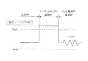
- FIG. 14 is a time chart for explaining a problem when setting burnout H in a conventional field device.
- FIG. 1 is a block diagram showing an outline of an embodiment of a field device according to the present invention.
- 100 is a field device according to the present invention
- 200 is a host device (monitoring device) connected to the field device 100 via a two-wire transmission line L (L1, L2).
- L two-wire transmission line
- the field device 100 is a differential pressure / pressure transmitter.
- the field device 100 includes a sensor unit 1 that generates an analog signal corresponding to the magnitude of pressure or differential pressure, an A / D converter 2 that converts the analog signal from the sensor unit 1 into a digital signal, A CPU 3 that samples a digital signal output from the A / D converter 2 to obtain a measured value of pressure / differential pressure, and a digital current value obtained by the CPU 3 within a predetermined current range (4 to 20 mA).
- a D / A converter 4 for converting to an analog signal
- a communication unit 5 for outputting an analog signal output from the D / A converter 4 to a two-wire transmission line L, and a two-wire transmission line L
- the power supply unit 6 that generates the operating power supply Vcc to each unit in its own device, and whether the output signal to the transmission line L at the time of abnormality detection is a burnout H signal or burnout L
- a DIP switch 7 that enables to the one of the selected configuration and includes a ROM 8, a RAM 9.
- the CPU 3 operates in accordance with a program stored in the ROM 8 while accessing the RAM 9.
- a program specific to this embodiment is provided.
- An abnormality diagnosis program for detecting various abnormalities occurring in the device and notifying the monitoring apparatus 200 is stored.
- the measurement value calculation unit 3-1, the transmission control unit 3-2 and the abnormality detection unit 3-3 are shown as functional blocks in the CPU 3, but the measurement value calculation unit 3-1, transmission The control unit 3-2 and the abnormality detection unit 3-3 are realized as a processing function according to a program in the CPU 3.
- the measured value calculation unit 3-1 samples the digital signal from the A / D converter 2 to obtain the measured value of the pressure / differential pressure, and performs D / A conversion as the digital measured value. To the device 4.
- the abnormality detection unit 3-3 monitors the outputs of the sensor unit 1, the A / D converter 2, the CPU 3, the D / A converter 4, the communication unit 5, and the power supply unit 6, and detects abnormalities in these units in its own device. Are detected as various abnormalities.
- the abnormality of the CPU 3 itself is diagnosed by monitoring the output from the measurement value calculation unit 3-1.
- This abnormality detection unit 3-3 corresponds to the abnormality detection means in the invention described in claim 1.
- the transmission control unit 3-2 receives the selection setting state of the burnout signal from the DIP switch 7, and according to the selection setting state of the burnout signal from the DIP switch 7, the abnormality detection unit 3-3 Whether the output signal to the transmission line L is a burnout H signal or a burnout L signal is determined, and the communication unit 5 is instructed. Further, when determining the burnout signal, it is possible to determine whether or not the burnout H signal can be output for the abnormality detected by the abnormality detecting unit 3-3, and to output the burnout H signal. When it is determined that it cannot be performed, an output signal to the transmission line L for the abnormality is set as a burnout L signal.
- the transmission control unit 3-2 corresponds to the burnout direction changing means in the invention described in claim 1
- the dip switch 7 corresponds to the burnout direction setting means in the invention described in claim 1.
- FIG. 2 shows a first example of processing operations executed in the transmission control unit 3-2.
- the transmission control unit 3-2 determines the type of the abnormality (step S202).
- the processing function for determining the type of abnormality in step S202 corresponds to the abnormality type determining means in the invention according to claim 2.
- the type of abnormality is an abnormality of the D / A converter 4 or the power supply unit 6, it is determined that there is a high possibility that the burnout H signal cannot be output, and the transmission to the transmission line L for the abnormality is determined.
- the output signal is a burnout L signal (step S203).
- the processing function for setting the burnout L signal in step S203 corresponds to the burnout changing means in the second aspect of the present invention.
- step S202 if the abnormality type is not an abnormality of the D / A converter 4 or the power supply unit 6, the transmission control unit 3-2 determines that there is a high possibility that the burnout H signal can be output. Then, according to the selection setting state of the burnout signal from the dip switch 7 (step S204), the burnout signal is output.
- the burnout H signal is set, the output signal to the transmission line L is set as the burnout H signal (step S205). If the burnout L signal is set, the output signal to the transmission line L is set. Is a burnout L signal (step S206).
- FIG. 3 shows a time chart of the output state of the burnout signal when the burnout H is set in the first example of this processing operation.
- the burnout L signal is always output, and the reliability of the abnormality notification when the burnout H is set increases.
- FIG. 4 shows a functional block diagram of the transmission control unit 3-2 when the first example of this processing operation is adopted.
- 3A1 is an abnormality type determination unit
- 3A2 is a burnout L forced output unit
- 3A3 is a burnout selection setting state confirmation unit
- 3A4 is a burnout H output unit
- 3A5 is a burnout L output unit.
- the determination unit 3A1 performs a processing operation corresponding to step S202 in the flowchart shown in FIG. 2, the burnout L forced output unit 3A2 performs a processing operation corresponding to step S203, and the burnout selection setting state confirmation unit 3A3 performs step S204.
- the burnout H output unit 3A4 performs the processing operation corresponding to step S205, and the burnout L output unit 3A5 performs the processing operation corresponding to step S206.
- the type of abnormality that may not be able to output the burnout H signal and the type of abnormality that is likely to be able to output the burnout H signal occur simultaneously.
- the burnout L signal is output with priority given to the type of abnormality that may not be able to output the burnout H signal.
- FIG. 5 shows a second example of the processing operation executed in the transmission control unit 3-2.
- the transmission control unit 3-2 confirms the selection setting state of the burnout signal from the dip switch 7 when an abnormality is detected by the abnormality detection unit 3-3 (step S201).
- the processing function in step S302 corresponds to the burnout signal selection setting state confirmation means in the third aspect of the present invention.
- step S303 if the selection setting state of the burnout signal from the DIP switch 7 is the burnout H signal, it is checked whether or not the burnout H signal can actually be output.
- the communication unit 5 is prohibited from outputting a signal to the transmission line L, and the measurement value calculation unit 3-1 is instructed to output a current value corresponding to the burnout H signal.
- the measurement value calculation unit 3-1 is instructed to output a current value corresponding to the burnout H signal.
- the transmission control unit 3-2 sets the output signal to the transmission line L for the abnormality as the burnout L signal (step S304). That is, an instruction is given to the communication unit 5 and a burnout L signal is output to the transmission line L.
- the processing in steps S303 and S304 corresponds to the burnout signal changing means in the invention as claimed in claim 3.
- step S303 If the burnout H signal can be actually output in step S303, the transmission control section 3-2 burns the output signal to the transmission line L according to the burnout signal selection setting state from the DIP switch 7. An out H signal is set (step S305).
- step S302 If the selection setting state of the burnout signal from the DIP switch 7 is the burnout L signal in step S302, the output signal to the transmission line L is immediately sent to the burnout L signal according to the selection setting state. (Step S306).
- FIG. 6 shows a time chart of the output state of the burnout signal when the burnout H is set in the second example of this processing operation.
- the burnout L signal is always output. The certainty of abnormality notification at the time of setting out H is increased.
- FIG. 7 shows a functional block diagram of the transmission control unit 3-2 when the second example of this processing operation is adopted.
- 3B1 is a burnout selection setting state confirmation section
- 3B2 is a burnout H output simulation section
- 3B3 is a burnout H output section
- 3B4 is a burnout L forced output section
- 3B5 is a burnout L output section.
- the burnout selection setting state confirmation unit 3B1 performs a processing operation corresponding to step S302 in the flowchart shown in FIG. 5, and the burnout H output simulation unit 3B2 performs a processing operation corresponding to step S303.
- Unit 3B3 performs a processing operation corresponding to step S305
- burnout L forced output unit 3B4 performs a processing operation corresponding to step S304
- burnout L output unit 3B5 performs a processing operation corresponding to step S306.
- the burnout H signal is actually output.
- the burnout L signal is output with priority given to abnormalities that cannot be performed.
- Example 2 In the above-described first embodiment, the field device including the dip switch 7 that enables selection between the burnout H signal and the burnout L signal has been described as an example. However, the output signal to the transmission line when an abnormality is detected is described. The characteristic technique in the present invention described in the first embodiment can be applied to a field device having only a burnout H signal.
- FIG. 8 shows the configuration of a field device (Example 2) in which only the burnout H signal is set as the output signal to the transmission line when an abnormality is detected.
- This field device 101 does not have the DIP switch 7 provided in the field device 100 shown in FIG. 1, and outputs to the transmission line L when an abnormality is detected with respect to the transmission control unit 3-2.
- a burnout H signal is preset as a signal.
- FIG. 9 shows a flowchart of a first example of processing operations executed by the transmission control unit 3-2 in the field device 101.
- the transmission control unit 3-2 determines the type of the abnormality (step S402).
- the type of abnormality is an abnormality of the D / A converter 4 or the power supply unit 6, it is determined that there is a high possibility that the burnout H signal cannot be output, and the transmission to the transmission line L for the abnormality is determined.
- the output signal is a burnout L signal (step S403). If the abnormality type is not an abnormality of the D / A converter 4 or the power supply unit 6, the output signal to the transmission line L is set as a burnout H signal (step S404).
- FIG. 10 shows a flowchart of a second example of the processing operation executed by the transmission control unit 3-2 in the field device 101.
- the transmission control unit 3-2 checks whether or not the burnout H signal can actually be output (step S502). ). If the burnout H signal cannot be actually output, the output signal to the transmission line L for the abnormality is set as the burnout L signal (step S503). When the burnout H signal can be output, the output signal to the transmission line L is set as the burnout H signal (step S504).
- the processing in the transmission control unit 3-2 and the abnormality detection unit 3-3 is realized as a processing function according to the program in the CPU 3, but the transmission control unit 3-2 and An abnormality diagnosis circuit having a processing function similar to that of the abnormality detection unit 3-3 may be provided separately.
- the field device of the present invention can be used in various fields such as process control as a field device that adjusts the value of a current flowing through a two-wire transmission line according to a measured value.
Priority Applications (3)
| Application Number | Priority Date | Filing Date | Title |
|---|---|---|---|
| EP09738719.5A EP2278571B1 (de) | 2008-04-28 | 2009-04-20 | Feldeinrichtung |
| US12/989,852 US8618808B2 (en) | 2008-04-28 | 2009-04-20 | Field device |
| CN2009801148357A CN102016950B (zh) | 2008-04-28 | 2009-04-20 | 现场仪表 |
Applications Claiming Priority (2)
| Application Number | Priority Date | Filing Date | Title |
|---|---|---|---|
| JP2008-116870 | 2008-04-28 | ||
| JP2008116870A JP5127551B2 (ja) | 2008-04-28 | 2008-04-28 | フィールド機器 |
Publications (1)
| Publication Number | Publication Date |
|---|---|
| WO2009133782A1 true WO2009133782A1 (ja) | 2009-11-05 |
Family
ID=41254999
Family Applications (1)
| Application Number | Title | Priority Date | Filing Date |
|---|---|---|---|
| PCT/JP2009/057846 WO2009133782A1 (ja) | 2008-04-28 | 2009-04-20 | フィールド機器 |
Country Status (6)
| Country | Link |
|---|---|
| US (1) | US8618808B2 (de) |
| EP (1) | EP2278571B1 (de) |
| JP (1) | JP5127551B2 (de) |
| KR (1) | KR101067461B1 (de) |
| CN (1) | CN102016950B (de) |
| WO (1) | WO2009133782A1 (de) |
Families Citing this family (4)
| Publication number | Priority date | Publication date | Assignee | Title |
|---|---|---|---|---|
| JP5656713B2 (ja) * | 2011-03-30 | 2015-01-21 | アズビル株式会社 | フィールド機器 |
| DE102013103454A1 (de) * | 2013-04-08 | 2014-10-09 | Endress + Hauser Gmbh + Co. Kg | Messumformerspeisegerät, System zum Einsatz in der Automatisierungstechnik, sowie Verfahren zum Bedienen eines solchen Systems |
| CN110887597B (zh) * | 2019-12-04 | 2021-10-26 | 北京麦普兹微电科技有限公司 | 一种两线制智能差压控制器变送器数显仪表 |
| JP7287376B2 (ja) * | 2020-10-26 | 2023-06-06 | 横河電機株式会社 | フィールド機器 |
Citations (4)
| Publication number | Priority date | Publication date | Assignee | Title |
|---|---|---|---|---|
| JPH0660287A (ja) * | 1992-08-10 | 1994-03-04 | Yokogawa Electric Corp | 2線式伝送器 |
| JPH0625073Y2 (ja) | 1988-04-26 | 1994-06-29 | 横河電機株式会社 | 2線式信号伝送器 |
| JPH08247881A (ja) | 1995-03-10 | 1996-09-27 | Hitachi Ltd | センサ診断機能付差圧・圧力伝送器 |
| JP2006323661A (ja) * | 2005-05-19 | 2006-11-30 | Yamatake Corp | 2線式フィールド機器および異常通知制御方法 |
Family Cites Families (3)
| Publication number | Priority date | Publication date | Assignee | Title |
|---|---|---|---|---|
| JP2005228732A (ja) * | 2004-01-15 | 2005-08-25 | Omron Corp | 故障検出装置 |
| JP5656713B2 (ja) * | 2011-03-30 | 2015-01-21 | アズビル株式会社 | フィールド機器 |
| DE102011110612A1 (de) * | 2011-08-16 | 2013-02-21 | GM Global Technology Operations LLC (n. d. Gesetzen des Staates Delaware) | Verfahren zum Erfassen eines Burnoutzustands, in dem angetriebene Räder zum Durchdrehen gebracht werden |
-
2008
- 2008-04-28 JP JP2008116870A patent/JP5127551B2/ja active Active
-
2009
- 2009-04-20 EP EP09738719.5A patent/EP2278571B1/de active Active
- 2009-04-20 US US12/989,852 patent/US8618808B2/en active Active
- 2009-04-20 CN CN2009801148357A patent/CN102016950B/zh active Active
- 2009-04-20 KR KR1020107021467A patent/KR101067461B1/ko active IP Right Grant
- 2009-04-20 WO PCT/JP2009/057846 patent/WO2009133782A1/ja active Application Filing
Patent Citations (4)
| Publication number | Priority date | Publication date | Assignee | Title |
|---|---|---|---|---|
| JPH0625073Y2 (ja) | 1988-04-26 | 1994-06-29 | 横河電機株式会社 | 2線式信号伝送器 |
| JPH0660287A (ja) * | 1992-08-10 | 1994-03-04 | Yokogawa Electric Corp | 2線式伝送器 |
| JPH08247881A (ja) | 1995-03-10 | 1996-09-27 | Hitachi Ltd | センサ診断機能付差圧・圧力伝送器 |
| JP2006323661A (ja) * | 2005-05-19 | 2006-11-30 | Yamatake Corp | 2線式フィールド機器および異常通知制御方法 |
Non-Patent Citations (1)
| Title |
|---|
| See also references of EP2278571A4 * |
Also Published As
| Publication number | Publication date |
|---|---|
| JP2009266070A (ja) | 2009-11-12 |
| CN102016950B (zh) | 2013-02-27 |
| EP2278571A1 (de) | 2011-01-26 |
| JP5127551B2 (ja) | 2013-01-23 |
| EP2278571B1 (de) | 2016-01-27 |
| KR20100115384A (ko) | 2010-10-27 |
| EP2278571A4 (de) | 2012-12-05 |
| US8618808B2 (en) | 2013-12-31 |
| US20110037478A1 (en) | 2011-02-17 |
| KR101067461B1 (ko) | 2011-09-27 |
| CN102016950A (zh) | 2011-04-13 |
Similar Documents
| Publication | Publication Date | Title |
|---|---|---|
| EP2609408B1 (de) | Messung der temperatur einer prozessflüssigkeit | |
| WO2009133782A1 (ja) | フィールド機器 | |
| JP6025573B2 (ja) | トランスミッタの監視方法および相応するトランスミッタ | |
| US10989574B2 (en) | Method for in-situ calibration of an analog measurement transmission path and corresponding apparatus | |
| JP5864748B2 (ja) | 2線プロセス制御ループ電流の診断装置及び方法 | |
| US8405378B2 (en) | Current generating device for the generation and simultaneous monitoring of a measuring current | |
| JP5074307B2 (ja) | フィールド機器 | |
| JP4999789B2 (ja) | フィールド機器 | |
| US20140058543A1 (en) | Method for configuring a field device and corresponding field device and system for parameterization | |
| US8959252B2 (en) | Method for configuring a field device and corresponding system for parameterization | |
| US9574925B2 (en) | Fluid measurement device having a circuit for precise flow measurement | |
| JP5091841B2 (ja) | フィールド機器 | |
| US20210149358A1 (en) | Communication system for automation and process engineering, and y selector switch unit for such a communication system | |
| CN104810783B (zh) | 模拟电流输出模块 | |
| KR20150074653A (ko) | Plc의 릴레이 출력모듈 및 이의 동작방법 | |
| JP4157687B2 (ja) | フィールド機器 | |
| US11391772B2 (en) | Signal transmission system | |
| JP7378378B2 (ja) | 炉外核計装装置 | |
| JP6775718B1 (ja) | アナログ入力装置及びアナログ入力装置の制御方法 | |
| US10735830B2 (en) | Transmitter | |
| JP2007065721A (ja) | サポートツール | |
| JPH09178593A (ja) | 圧力検出器 | |
| KR101477895B1 (ko) | 아날로그 출력모듈의 오프셋 게인 설정방법 | |
| JP2012073074A (ja) | 電子機器 | |
| JP2007336332A (ja) | 伝送器 |
Legal Events
| Date | Code | Title | Description |
|---|---|---|---|
| WWE | Wipo information: entry into national phase |
Ref document number: 200980114835.7 Country of ref document: CN |
|
| 121 | Ep: the epo has been informed by wipo that ep was designated in this application |
Ref document number: 09738719 Country of ref document: EP Kind code of ref document: A1 |
|
| ENP | Entry into the national phase |
Ref document number: 20107021467 Country of ref document: KR Kind code of ref document: A |
|
| WWE | Wipo information: entry into national phase |
Ref document number: 12989852 Country of ref document: US |
|
| NENP | Non-entry into the national phase |
Ref country code: DE |
|
| WWE | Wipo information: entry into national phase |
Ref document number: 2009738719 Country of ref document: EP |