WO2009104572A1 - 分離装置及び分離方法 - Google Patents
分離装置及び分離方法 Download PDFInfo
- Publication number
- WO2009104572A1 WO2009104572A1 PCT/JP2009/052621 JP2009052621W WO2009104572A1 WO 2009104572 A1 WO2009104572 A1 WO 2009104572A1 JP 2009052621 W JP2009052621 W JP 2009052621W WO 2009104572 A1 WO2009104572 A1 WO 2009104572A1
- Authority
- WO
- WIPO (PCT)
- Prior art keywords
- chamber
- inflow
- screen
- separation
- inflow chamber
- Prior art date
- Legal status (The legal status is an assumption and is not a legal conclusion. Google has not performed a legal analysis and makes no representation as to the accuracy of the status listed.)
- Ceased
Links
Images





Classifications
-
- E—FIXED CONSTRUCTIONS
- E03—WATER SUPPLY; SEWERAGE
- E03F—SEWERS; CESSPOOLS
- E03F5/00—Sewerage structures
- E03F5/14—Devices for separating liquid or solid substances from sewage, e.g. sand or sludge traps, rakes or grates
-
- B—PERFORMING OPERATIONS; TRANSPORTING
- B01—PHYSICAL OR CHEMICAL PROCESSES OR APPARATUS IN GENERAL
- B01D—SEPARATION
- B01D29/00—Filters with filtering elements stationary during filtration, e.g. pressure or suction filters, not covered by groups B01D24/00 - B01D27/00; Filtering elements therefor
- B01D29/01—Filters with filtering elements stationary during filtration, e.g. pressure or suction filters, not covered by groups B01D24/00 - B01D27/00; Filtering elements therefor with flat filtering elements
- B01D29/03—Filters with filtering elements stationary during filtration, e.g. pressure or suction filters, not covered by groups B01D24/00 - B01D27/00; Filtering elements therefor with flat filtering elements self-supporting
-
- B—PERFORMING OPERATIONS; TRANSPORTING
- B01—PHYSICAL OR CHEMICAL PROCESSES OR APPARATUS IN GENERAL
- B01D—SEPARATION
- B01D29/00—Filters with filtering elements stationary during filtration, e.g. pressure or suction filters, not covered by groups B01D24/00 - B01D27/00; Filtering elements therefor
- B01D29/11—Filters with filtering elements stationary during filtration, e.g. pressure or suction filters, not covered by groups B01D24/00 - B01D27/00; Filtering elements therefor with bag, cage, hose, tube, sleeve or like filtering elements
- B01D29/31—Self-supporting filtering elements
-
- B—PERFORMING OPERATIONS; TRANSPORTING
- B01—PHYSICAL OR CHEMICAL PROCESSES OR APPARATUS IN GENERAL
- B01D—SEPARATION
- B01D29/00—Filters with filtering elements stationary during filtration, e.g. pressure or suction filters, not covered by groups B01D24/00 - B01D27/00; Filtering elements therefor
- B01D29/44—Edge filtering elements, i.e. using contiguous impervious surfaces
- B01D29/445—Bar screens
-
- B—PERFORMING OPERATIONS; TRANSPORTING
- B01—PHYSICAL OR CHEMICAL PROCESSES OR APPARATUS IN GENERAL
- B01D—SEPARATION
- B01D29/00—Filters with filtering elements stationary during filtration, e.g. pressure or suction filters, not covered by groups B01D24/00 - B01D27/00; Filtering elements therefor
- B01D29/88—Filters with filtering elements stationary during filtration, e.g. pressure or suction filters, not covered by groups B01D24/00 - B01D27/00; Filtering elements therefor having feed or discharge devices
- B01D29/90—Filters with filtering elements stationary during filtration, e.g. pressure or suction filters, not covered by groups B01D24/00 - B01D27/00; Filtering elements therefor having feed or discharge devices for feeding
- B01D29/906—Special treatment of the feed stream before contacting the filtering element, e.g. cutting
-
- B—PERFORMING OPERATIONS; TRANSPORTING
- B01—PHYSICAL OR CHEMICAL PROCESSES OR APPARATUS IN GENERAL
- B01D—SEPARATION
- B01D2201/00—Details relating to filtering apparatus
- B01D2201/02—Filtering elements having a conical form
Definitions
- the present invention relates to an apparatus and a separation method for separating solids contained in a liquid flowing through drainage flowing through a sewer pipe or a wastewater treatment facility in a factory.
- Wastewater such as rainwater flowing into sewers laid in urban areas is partly stored or discharged into the ground by facilities that store or infiltrate rainwater, and the rest is discharged into rivers.
- the rainwater drainage that falls on the surface of the earth and flows through the sewers is mixed with solids such as earth and sand, various garbage, papers, fallen leaves, etc., and when these solids are discharged into the river, the water quality If pollution occurs and it flows into rainwater storage and infiltration facilities, it is necessary to frequently maintain the facilities, which is disadvantageous in terms of cost.
- rainwater storage tanks and the like for measures against inundation due to torrential rain rainwater temporarily stored underground without removing solids must be pumped up and released into rivers in fine weather. Solid matter will also be released into the river at the same time, causing river water pollution and environmental pollution problems. Therefore, as a means for avoiding such water pollution and environmental pollution, a wastewater separator for separating solids is provided in a part of the sewer.
- Patent Document 1 discloses a separation device that combines a swirl flow generation method and a screen separation method.
- a cylindrical screen is disposed below a separation tank having a circular plane cross section, and a swirling flow is generated in the tank by supplying waste water in a tangential direction from above the separation tank. Solids are separated by a screen arranged in the screen, and only waste water is allowed to pass outside the screen.
- the conventional separation device that combines the swirl flow generation method and the screen separation method has to connect the drainage supply pipe in the tangential direction of the circular peripheral wall of the separation tank. Processing is required.
- the cylindrical screen has a problem that the structure is complicated and the cost is increased.
- the separation device since the separation device has a structure that generates a swirling flow in the horizontal direction, a large installation area is required in the lateral direction perpendicular to the pipe line direction.
- a separator in the middle of a drainage channel along a sewer or street, or when installing it in the middle of a pipeline such as a drainage channel provided in a passage in a factory, etc.
- the installation space is sufficient, but the installation space in the horizontal direction perpendicular to it is often limited. For this reason, the conventional separation apparatus has a great restriction on the selection of the installation location.
- the present invention aims to solve the problems associated with the use of the screen and the problems related to installation space and pipe connection in the conventional separation apparatus, and to provide a new separation apparatus and separation method therefor. With the goal.
- a first separation device of the present invention that solves the above-described problems is a device for separating solids contained in an inflowing liquid, a separation tank, a partition plate that partitions the inside of the separation tank into an inflow chamber and an outflow chamber, A screen provided on the plate; an inflow portion formed in the inflow chamber; and a discharge portion formed in the outflow chamber.
- the liquid flowing in from the inflow portion is reversed in the inflow chamber so as to vertically move into the inflow chamber.
- a guiding portion for forming a swirling flow is provided, and the screen is arranged along a side surface of the swirling flow to be formed.
- the second separator is the above-described first separator, wherein the separation tank is formed into a square shape having a long axis and a short axis, an oval shape, or a square shape having a rectangular shape on the inflow portion side and a circular shape on the discharge portion side.
- the partition plate is provided parallel or deflected in the long axis direction, the inflow portion in the inflow chamber is formed at one end portion in the long axis direction, and the discharge portion in the outflow chamber is the other end in the long axis direction It is formed in the part.
- the third separation device is characterized in that, in the second separation device, two screens are provided, and the screens are provided in parallel with each other or so that the distance between the screens decreases as the distance from the inflow portion increases. It is.
- the fourth separation device may be any one of the first to third separation devices, wherein the screen includes a wedge wire screen in which a plurality of wedge wires having a wedge-shaped cross section are arranged in the vertical direction. A part of the inner surface on the inflow chamber side is formed at the portion.
- the fifth separator is the above-described fourth separator, wherein the axis from the head to the tip of each wedge wire is inclined to the downstream side of the formed swirl flow in the vertical direction, and the axis is In addition, it is characterized in that they are inclined in directions opposite to each other in accordance with the upper flow and the lower flow in the swirling flow in the vertical direction.
- the sixth separation device is characterized in that, in any of the first to fifth separation devices, a solid discharge unit is provided at the bottom of the inflow chamber.
- the seventh separation device is characterized in that, in any of the first to sixth separation devices, a drainage part is provided at the bottom of the outflow chamber.
- an eighth separation device according to any one of the first to fifth separation devices, wherein the inflow portion is formed at an upper portion of the inflow chamber, and the swirling flow rises from the lower portion of the inflow chamber to the inflow portion side.
- a guiding portion is provided, and a gap is provided between the tip of the guiding portion and the peripheral wall where the swirling flow rises.
- the ninth separator is the above-described first to eighth separator, wherein an overflow part is provided on the upper part of the partition plate to communicate the inflow chamber and the outflow chamber, and the discharge part has an oil content or a floating property.
- a dam portion for preventing inflow of solid matter is provided.
- the tenth separation device of the present invention is a device for separating solids contained in an inflowing liquid, provided in a separation tank, a partition plate for partitioning the inside of the separation tank into an inflow chamber and an outflow chamber, and the partition plate.
- a partition Formed in a screen, a partition that divides the inflow chamber into an upper first chamber and a lower second chamber, an opening formed in the partition, a supply section formed in the first chamber, and an outflow chamber
- the first chamber is provided with a guide unit for reversing the inflow direction of the liquid flowing in from the supply unit to generate a swirling flow in the vertical direction in the first chamber, It is disposed along the side surface of the swirling flow in the vertical direction formed in the first chamber, and its lower edge extends to at least the partition, and a solid depositing portion that flows into the second chamber from the opening is provided. It is characterized by being formed.
- the first separation method of the present invention is a method for separating solids contained in an inflowing liquid, provided in a separation tank, a partition plate for partitioning the inside of the separation tank into an inflow chamber and an outflow chamber, and the partition plate.
- a separation device equipped with a screen an inflow portion formed in the inflow chamber, and a discharge portion formed in the outflow chamber, the liquid flowing from the inflow portion is reversed to form a vertical swirl flow in the inflow chamber
- the solid matter is separated by the screen arranged along the side surface of the swirling flow to be formed.
- the second separation method is the above-described first separation method, wherein the screen is configured by a wedge wire screen in which a plurality of wedge wires having a wedge-shaped cross section are arranged in the vertical direction. A part of the inner surface is formed, and an axis line from the head to the tip of each wedge wire is inclined to the downstream side of the formed swirl flow in the vertical direction.
- the third separation method is characterized in that, in the second separation method, the average particle size of the solid matter to be separated is in the range of 10 ⁇ m to 1 mm.
- the first separation device of the present invention reverses the liquid flowing in from the inflow section (for example, sewage flowing through a sewer pipe, drainage in a paper mill, waste liquid in a brewery, etc., hereinafter referred to as “flowing liquid”).
- a guiding portion for forming a vertical swirling flow in the inflow chamber is provided in the inflow chamber, and a screen is arranged along the side surface of the swirling flow to be formed.
- the screen is arranged on the side surface of the swirling flow generated in the vertical direction, so that the solid substance flows almost in parallel with the flowing liquid along the screen.
- the length of the screen can be increased in the pipeline direction, so that a large installation area in the lateral direction perpendicular to the pipeline direction is not necessary.
- pipes such as pipes connected to the inflow section can be connected in a direction perpendicular to the surface of the peripheral wall of the separation tank, the construction and design of pipe connection and the like are simplified, and a connection structure that does not easily leak water is provided. can get.
- the separation tank in the first separation device, is formed in a square shape or an elliptic shape in which the plane section has a major axis and a minor axis, or a square shape in which the inflow portion side is square and the discharge portion side is circular.
- the partition plate is provided parallel to or deflected in the long axis direction, the inflow portion in the inflow chamber is formed at one end in the long axis direction, and the discharge portion in the outflow chamber is formed in the other end in the long axis direction Can be formed on the part.
- the separation tank in the second separator, when the separation tank is formed in a square shape or an elliptical shape having a long cross section and a short cross section, the two screens are provided, and the screens are mutually connected. It can be provided so that the interval decreases as the distance from the parallel or inflow portion increases.
- the separation processing capacity can be increased almost twice as compared with a single screen without increasing the size of the separation tank, and the flow center of the flowing liquid can be lengthened.
- a wedge wire screen in which a plurality of wedge wires having a wedge-shaped cross section are arranged in the vertical direction is used as the screen, and the head of each wedge wire is used.
- the head of each wedge wire is used.
- a wedge wire screen Using such a wedge wire screen, fine solids can be separated efficiently.
- a surface on the inflow chamber side is formed at the head of each wedge wire constituting the wedge wire screen, and an arrangement shape of the head is formed so as to form a horizontal swirl flow in the flowing liquid supplied from the supply unit. Since it comprised, the fine solid substance adhering to a wedge wire screen is also easily peeled by the swirl flow. Therefore, the wedge wire screen can be operated in a state where it is difficult to clog.
- the axis line from the head to the tip of each wedge wire is inclined to the downstream side of the formed swirl flow in the vertical direction.
- the axis from the head to the tip of each wedge wire can be inclined in opposite directions according to the upper and lower flow in the vertical swirl flow. If comprised in this way, even if it is a screen part arrange
- the end of the head on the upstream side of the swirl flow is the end of the head on the downstream side. It protrudes from the section toward the inflow chamber. Therefore, the swirling flow collides with the protruding end and the flowing liquid is efficiently drawn into the slit by the Coanda effect, and as a result, the aperture ratio of the screen can be substantially increased. Therefore, even if the porosity of the screen becomes very small by reducing the slit interval so that solids of several microns to several tens of microns can be separated, the screen area is suppressed due to high liquid passing efficiency. And further downsizing of the apparatus can be achieved.
- a solid discharge unit in any of the first to fifth separators, can be provided at the bottom of the inflow chamber. If comprised in this way, when installing a separator on the ground, the solid substance accumulate
- a drainage section can be provided at the bottom of the outflow chamber.
- the inflow portion is formed in the upper portion of the inflow chamber, and the swirling flow rises from the lower portion in the inflow chamber to the inflow portion side.
- a guiding part may be provided, and a gap may be provided between the leading end of the guiding part and the peripheral wall where the swirling flow rises.
- an overflow portion that communicates the inflow chamber and the outflow chamber is provided in the upper portion of the partition plate, and oil or floating solids are provided in the discharge portion.
- a dam portion for preventing inflow of objects can be provided.
- a tenth separation device of the present invention includes a separation tank, a partition plate that divides the inside of the separation tank into an inflow chamber and an outflow chamber, a screen provided in the partition plate, and an inflow chamber on the upper first chamber and the lower side.
- a partition body that is partitioned into a second chamber, an opening formed in the partition body, a supply portion formed in the first chamber, and a discharge portion formed in the outflow chamber are provided. If comprised in this way, the solid substance isolate
- the liquid flowing in from the inflow portion is inverted to form a vertical swirl flow in the inflow chamber, and the side surface of the swirl flow formed is formed.
- the solid matter is separated by a screen arranged along the line.
- the separation method of the present invention since the screen is arranged on the side surface of the swirling flow generated up and down, the solid matter flows in parallel along the screen surface together with the flowing liquid, so that the solid matter hardly adheres to the screen. Solids contained in the flowing liquid can be efficiently separated without clogging and without requiring a large installation area in the lateral direction perpendicular to the pipe line direction.
- a wedge wire screen in which a plurality of wedge wires having a wedge-shaped cross section are arranged in the vertical direction is used as the screen, and the inner surface on the inflow chamber side at the head of each wedge wire. And the axis line from the head to the tip of each wedge wire can be inclined to the downstream side of the formed swirl flow in the vertical direction.
- a wedge wire screen Using such a wedge wire screen, fine solids can be separated efficiently.
- a surface on the inflow chamber side is formed at the head of each wedge wire constituting the wedge wire screen, and an arrangement shape of the head is formed so as to form a horizontal swirl flow in the flowing liquid supplied from the supply unit. Since it comprised, the fine solid substance adhering to a wedge wire screen is also easily peeled by the swirl flow. Therefore, the wedge wire screen can be operated in a state where it is difficult to clog.
- the end of the head on the upstream side of the swirl flow is the end of the head on the downstream side. It protrudes from the section toward the inflow chamber. Therefore, the swirling flow collides with the protruding end portion, and the flowing liquid is efficiently drawn into the slit by the Coanda effect. As a result, the aperture ratio of the screen can be substantially increased. Accordingly, the liquid passing efficiency can be increased even if the interval between the slits is reduced so that a solid matter of several microns to several tens of microns can be separated.
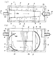
- FIG. 1A is a plan view of a separation apparatus according to a first embodiment
- FIG. 2B is a cross-sectional view taken along the line AA of FIG.
- FIG. 2A is a plan view of a second embodiment of the separating apparatus
- FIG. 2B is a cross-sectional view taken along the line BB of FIG.
- FIG. 3A is a plan view of a third embodiment of the separation device
- FIG. 3B is a cross-sectional view taken along the line CC of FIG.
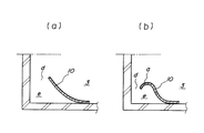
- (A) is an example of the guidance part which does not provide an extension part
- (b) is an example of a guidance part which provided a small circular arc extension part.
- FIG. 5A is a plan view of a fifth embodiment of the separation apparatus, and FIG. 5B is a sectional view taken along the line DD of FIG.
- FIG. 6A is a plan view of a sixth embodiment of the separator, and FIG. 5B is a cross-sectional view taken along line EE of FIG. FIG.
- FIG. 7A is a plan view of a seventh embodiment of the separator
- FIG. 5B is a cross-sectional view taken along line FF in FIG.
- FIG. 8A is a plan view of an eighth embodiment of the separating apparatus
- FIG. 5B is a sectional view taken along line GG of FIG.
- FIG. 9A is a plan view of the ninth embodiment of the separator
- FIG. 9B is a cross-sectional view taken along line HH of FIG.
- FIG. 1A and 1B show a first embodiment of a separation apparatus according to the present invention, in which FIG. 1A is a plan view and FIG. 1B is a sectional view taken on line AA of FIG.
- the separation device 1 is formed in a separation tank 2, a partition plate 5 that partitions the inside of the separation tank 2 into an inflow chamber 3 and an outflow chamber 4, an inflow portion 6 formed in the upper portion of the inflow chamber 3, and an upper portion of the outflow chamber 4.
- the partition plate 5 is provided with a screen 8. Note that the screen 8 can be directly attached to the peripheral wall portion of the separation tank 2 without providing the partition plate 5, and in this case, the screen 8 also serves as the partition plate 5.
- the separation tank 2 in FIG. 1 is formed in a rectangular shape with a long cross section having a major axis and a minor axis. However, the separation tank 2 may be oval or square on the inflow side and circular on the discharge side. It can be made of steel, FRP (fiber reinforced plastic), or resin such as polyethylene.
- FRP fiber reinforced plastic
- resin such as polyethylene
- the inflow portion 6 is a through hole whose axial direction formed on the peripheral wall of the separation tank 2 is perpendicular to the peripheral wall surface, and a short tube 6 a is connected to the inflow portion 6.
- the discharge part 7 is a through hole whose axial direction is perpendicular to the peripheral wall surface formed on the peripheral wall of the separation tank 2, and a short pipe 7 a is connected to the outflow part 7.
- piping etc. which comprise a sewer pipe can be connected to these short pipes 6a and 7a, omit at least one of the short pipes 6a and 7a and connect piping etc. directly to the inflow part 6 or the discharge part 7. You can also.
- An arcuate guiding portion 10 for reversing and a guiding portion 10a for changing the direction of the swirling flow rising along the peripheral wall in the horizontal direction are provided inside the inflow chamber 3.
- a vertical swirling flow is formed in the chamber 3.
- a gap d is provided between the front end of the guiding portion 10 and the peripheral wall where the swirling flow rises, and a solid accumulation portion e is formed in a region below the gap d.
- the guiding portion 10 has a main body portion formed in an arc shape, and an extension portion a extending in the lateral direction is provided at the arc-shaped tip portion.
- the guiding portions 9, 10, 10a can be made of a material such as steel, FRP, resin such as polyethylene, concrete or the like. Further, in this embodiment, the inclined surface 2a is formed on a part of the bottom of the separation tank 2 on the inflow part 6 side and the discharge part 7 side to further enhance the action of forming the swirling flow in the vertical direction.
- the partition plate 5 is provided so as to be deflected with respect to the major axis direction of the separation tank 2. That is, as shown in FIG. 1A, the end portion on the inflow portion 6 side of the partition plate 5 is fixed at a position close to one peripheral wall in the short axis direction of the separation tank 2, and the end portion on the discharge portion 7 side is The separation tank 2 is fixed at a position close to the other peripheral wall in the minor axis direction. Therefore, the partition plate 5 is provided obliquely with respect to the major axis when viewed from above, that is, deflected in the major axis direction, and the screen 8 provided thereon is also deflected in the major axis direction.
- a punching metal screen made of a punching metal in which a small-diameter hole is punched out by pressing in a metal plate such as stainless steel generally used in this field can be used.
- the hole diameter that can be processed into the plate thickness is several millimeters.
- solids having an average particle diameter of about several microns to 1 mm it is desirable to use a wedge wire screen suitable for such separation.
- FIG. 1 uses a wedge wire screen. Next, the wedge wire screen will be specifically described.
- FIG. 6A is a perspective view of the wedge wire screen 8 (used as the screen 8 of FIG. 1) viewed from the front
- FIG. 6B is a perspective view of the wedge wire screen 8 viewed obliquely from above.
- the wedge wire screen 8 is formed by arranging a plurality of wedge wires 8a having a wedge-shaped cross section in parallel, and minute slits 8b of about 10 ⁇ m to 1 mm are formed between the wedge wires 8a.
- Each wedge wire 8a is fixed to a plurality of support bars 8c by spot welding or the like.
- Each wedge wire 8a and support bar 8c are made of a corrosion-resistant metal material such as stainless steel.
- Each slit 8b formed in the wedge wire screen 8 prevents the passage of solid matter of about 10 ⁇ m to 1 mm, and allows only a flowing liquid containing solid matter smaller than the slit width to pass.
- the wedge wire screen 8 is provided on the partition plate 5 so that the axial direction of each wedge wire 8a coincides with the vertical direction of the separation tank 2, as shown in FIG.
- FIG. 7 is a partially enlarged cross-sectional view of the wedge wire 8a and the slit 8b constituting the wedge wire screen 8 shown in FIG.
- the wedge wires 8a having a wedge-shaped cross section are arranged in parallel with each other at a predetermined interval, and the surface of the head 8d forms a part of the surface on the inflow chamber side.
- the wedge axis S extending in the vertical direction from the surface of the head 8d is inclined downstream in the vertical swirl flow direction along the inner surface of the inflow chamber 3 indicated by the arrow L.
- the angle ⁇ between the swirling flow direction L and the surface of the head 8d is set to 3 to 8 degrees, usually about 5 degrees.
- each wedge wire 8a When the axis S of each wedge wire 8a is inclined in this way, as shown in the drawing, the end 8e of the head 8d on the upstream side of the swirl flow is located inside the inflow chamber 5 from the end 8f of the head 8d on the downstream side. Protrude in the direction. Therefore, the swirling flow collides with the protruding end portion 8e of each wedge wire 8a and is efficiently drawn into the slit 8b by the Coanda effect. Therefore, if the slit width is reduced to separate solids in micron units, the aperture ratio of the screen becomes very small, but the liquid permeability is improved by the Coanda effect and the aperture ratio of the screen is substantially increased. Demonstrate. When the liquid permeability can be improved in this way, the separation processing capability can be maintained at a considerable level even if the slit interval is extremely small in order to separate the fine solid matter.
- the wedge wire screen 8 shown in FIG. 1 is divided into upper and lower portions with an intermediate portion in the vertical direction as a boundary.
- the axis S of the wedge extending in the vertical direction from the surface of the head 8d in the upper wedge wire screen 8 and the lower wedge wire screen 8 is inclined in the opposite direction to the inside of the inflow chamber 3 indicated by arrows. It inclines in the downstream of the swirl flow direction of the up-down direction along.
- this space portion has an oil content or a floating property together with a flowing liquid that cannot pass through the screen 8 when a large amount of the flowing liquid and an oily or floating solid matter flow into the inflow chamber 3 in a heavy rain.
- An overflow portion 5a for overflowing solid matter to the outflow chamber is formed.
- a dam portion 7b is provided on the discharge chamber 7 on the outflow chamber 4 side.
- the dam portion 7b prevents oil and floating solids overflowing to the outflow chamber side from being discharged from the discharge portion to the downstream side.
- the flowing liquid When the flowing liquid is supplied from the upstream side of the pipe line through the inflow portion 6 formed in the upper part of the inflow chamber 3 as indicated by the arrow, the flowing liquid forms a vertical swirling flow inside the inflow chamber 3. That is, while the supplied liquid is restricted by the surface of the partition plate 5 (and the screen 8) on the side of the inflow chamber 3 and the peripheral wall surface of the separation tank 2 on the opposite side, the upper part of the inflow chamber 3 is horizontally oriented. And then descends, guided by the downstream guide section 9, then changes direction and returns to the upstream side through the lower part of the inflow chamber 3 as indicated by the arrow, from which it is guided to the upstream guide section 10. Ascending, the direction is changed by the guiding portion 10a, and again flows horizontally in the upper part of the inflow chamber 3, so that a swirling flow in the vertical direction is continuously formed in the inflow chamber 3 as long as the supply of the flowing liquid is continued.
- the gap d is provided between the tip of the guide portion 10 and the peripheral wall where the swirling flow rises, a portion close to the peripheral wall of the swirling flow to be lifted is pushed out toward the peripheral wall.
- the flow rate decreases and solid matter having a relatively large specific gravity enters the flow rate reduction region, the solids lose their rising force and settle down through the gap. Then, an accumulation part e for accumulating solid contents is formed in a region below the gap d. The accumulated solid matter can be taken out appropriately.
- the guide portion 10 has an arc-shaped main body, and an extension portion a extending in the lateral direction is provided at the tip portion thereof.
- an extension portion a By providing such an extension portion a, a portion close to the peripheral wall in the swirling flow Is pushed out in the direction of the peripheral wall, an attracting action along the extension part a due to the Coanda effect is added, and the solid sedimentation action is also increased.
- FIG. 4A shows an example of the guiding part 10 without the extension part a
- FIG. 4B shows an example of the guiding part 10 with the small arc-shaped extension part a. Any of these derivatives 10 shown in FIGS. 4A and 4B can be used in the present invention.
- the swirl flow in the vertical direction circulates in the inflow chamber 3 as described above.
- the upper surface of the swirl flow bundle flows horizontally from the inflow portion 6 on the downstream side.
- the guiding portion 9 descends and returns to the upstream side through the lower portion of the inflow chamber 3, it becomes the lower surface.
- the lower surface of the swirl flow bundle when flowing in the horizontal direction from the inflow portion 6 is guided and lowered by the downstream guide portion 9 and becomes the upper surface when returning to the upstream side through the lower portion of the inflow chamber 3.
- the position of the screen 8 is arrange
- the screen 8 provided on the partition plate 5 is arranged along the side surface of the vertical swirling flow formed as described above, and a part of the swirling flow passes through the screen 8 to the outflow chamber 4 side. To do.
- the flowing liquid that has flowed into the outflow chamber 4 passes through the discharge section 7 and is discharged to the downstream side of the pipeline.
- the wedge wire screen 8 is used as the screen 8 as described above, fine solids can also be separated efficiently.
- the solid matter blocked from passing to the outflow chamber 4 side by the screen 8 is circulated in the inflow chamber 3 as it is in a vertical swirling flow. At that time, a part of the solid matter adheres to the surface of the screen 8, but since the screen 8 is installed on the side surface of the vertical swirling flow, the solid matter attached to the screen 8 is swirling in the vertical direction. Since it peels, there is no possibility that the screen 8 will be clogged.
- FIG. 2 is a second embodiment of the separation apparatus of the present invention, where (a) is a plan view and (b) is a cross-sectional view taken along the line BB of (a).
- the difference of the separating apparatus 1 of the second embodiment from the example of FIG. 1 is that two screens 8 are used, and the downstream end portions of the two screens 8 are connected to each other via a guide portion 9.
- the configuration is the same as in the example of FIG. Therefore, in FIG. 2, the same parts as those in FIG.
- the guide portion 9 in the second embodiment is composed of a U-shaped plate whose longitudinal section is formed in an arc shape and side plates that close both sides thereof. Along one end of each partition plate 5 is connected.
- induction part 9 of a present Example also serves as a part of partition plate 5.
- FIG. The two partition plates 5 are arranged so that the distance between them becomes smaller as they move away from the inflow portion 6, and the two screens 8 provided on each partition plate 5 also move away from the inflow portion 6 toward the downstream side. Are arranged so that the distance between them becomes smaller.
- the inside surrounded by the two partition plates 5 and the guide portion 9 constitutes the inflow chamber 3, and the inside surrounded by the two partition plates 5, the outside of the guide portion 9 and the peripheral wall of the separation tank 2 is the outflow chamber. 4 is configured.
- the flowing liquid is supplied from the upstream side of the pipe line to the substantially central portion of the two partition plates 5 as shown by the arrow through the inflow portion 6 formed in the upper part of the inflow chamber 3, the flowing liquid is divided into two sheets. While the both sides of the partition plate 5 (and the two screens 8) are restricted, a swirling flow in the vertical direction is formed inside the inflow chamber 3. That is, the supplied liquid flows horizontally in the upper part of the inflow chamber 3 and descends while being guided by the downstream guide portion 9, and then changes direction and passes through the lower part of the inflow chamber 3 as shown by the arrow in the upstream side. From there, it rises and changes direction while being guided by the upstream guiding portion 10, and the direction is changed by the guiding portion 10 a to form a swirling flow that again flows in the horizontal direction over the upper portion of the inflow chamber 3.
- Each screen 8 provided on the two partition plates 5 is arranged along the side surface of the swirling flow in the vertical direction, and part of the swirling flow passes through the two screens 8 to the outflow chamber 4 side. Then, the liquid flowing into the outflow chamber 4 passes through the discharge portion 7 and is discharged to the downstream side of the pipe.
- the wedge wire screen 8 is used as the two screens 8, and the use of the two screens 8 causes the solid matter contained in the flowing liquid to be shifted to one screen 8. And a fine solid can be efficiently separated.
- the partition plate 5 can be omitted. In this case, since the screen 8 also serves as the partition plate 5, both end portions thereof are directly connected to the peripheral wall of the inflow chamber 3 and the guide portion 9.
- FIG. 3 shows a third embodiment of the separation apparatus of the present invention, in which (a) is a plan view and (b) is a cross-sectional view taken along the line CC of (a).
- the separation device 1 of the third embodiment is a modification of the embodiment of FIG. 2, and the difference from the example of FIG. 2 is that the two partition plates 5 are parallel to each other from the inflow portion 6 toward the downstream side.
- the two screens 8 provided on each partition plate 5 are also arranged parallel to each other from the inflow portion 6 toward the downstream side, and extend horizontally to the intermediate portion of the inflow chamber 3.
- This is the third point that the derivative 11 made of a rectangular plate material is provided, and the rest is configured in the same manner as in the example of FIG. Therefore, the same parts as those in FIG.
- the two screens 8 are arranged so that the distance between them becomes smaller as they move away from the inflow portion 6 as shown in FIG. 3 and the case where the screen 8 is arranged in parallel with each other from the inflow portion 6 toward the downstream side as shown in FIG. 3, there is no substantial difference between the two. 2 is slightly better due to the Coanda effect when arranged as shown in FIG. 2, but the adhesion of solid matter to the screen tends to be less in FIG. 3 where the two screens 8 are parallel.
- the plate surface of the derivative 11 is arranged parallel to the horizontal direction of the inflow chamber 3, and the main area inside the inflow chamber 3 is divided into upper and lower portions by the plate surface, thereby Since the flow of the upper side of the derivative 11 from the inflow portion 6 to the downstream side and the flow of the lower side of the derivative 11 from the guide portion 9 toward the upstream side of the inflow portion 6 are clearly separated and guided, The swirl flow is more easily and reliably formed.
- the screen 8 is a wedge wire screen 8, and the wedge wire screen 8 is divided into upper and lower parts, and fixed with the guide portion 11 sandwiched between the divided positions.
- the axis s from the head 8 d of each wedge wire 8 a of the upper wedge wire screen 8 toward the tip portion is on the discharge unit 7 side (the swirling flow side).
- the axis s from the head 8d of each wedge wire 8a of the lower wedge wire screen 8 toward the tip is inclined toward the inflow portion 6 (downstream of the swirl flow). That is, the axis s from the head 8d of each wedge wire 8a of the upper and lower wedge wire screens 8 toward the tip is inclined in opposite directions according to the upper flow and the lower flow in the vertical swirl flow.
- the wedge wire screen 8 can be integrally formed without being divided into upper and lower parts.
- a mounting bracket is provided in the middle portion of the wedge wire screen 8, and the derivative 11 is attached to the mounting bracket with a bolt or the like. Can be attached.
- the derivative 11 used in this example can also be used in the example of FIG.
- the guide unit 10 used in FIG. 2 can be added.
- the partition plate 5 can be omitted. In this case, since the screen 8 also serves as the partition plate 5, both end portions thereof are directly connected to the peripheral wall of the inflow chamber 3 and the guide portion 9.
- FIG. 5 is a partial cross-sectional view showing a fourth embodiment of the separation apparatus of the present invention, in which the lower part of the inflow chamber 3 and the outflow chamber 4 in the example of FIG. 2 or the example of FIG. 3 is modified.
- the fourth embodiment is different from the example of FIG. 2 or FIG. 3 in that a tapered portion is formed at the bottom of the inflow chamber 3 and a solid discharge unit 12 is provided at the bottom of the tapered portion.
- the drainage part 13 is connected to the peripheral wall part in contact with the bottom part of the outflow chamber 4, and the rest is configured similarly to the example of FIG. 2 or FIG. 3. Accordingly, portions other than the different portions are omitted in the drawing.
- the discharge unit 12 in the fourth embodiment is used to appropriately discharge the solid matter accumulated in the inflow chamber 3 to the outside.
- the discharge part 12 is comprised by the opening 12a and the lid 12b which can be opened and closed which closes it, and can open
- the drainage unit 13 in the fourth embodiment removes the remaining water from the outflow chamber 4 side when the operation of the separation tank 2 is stopped to perform internal cleaning or maintenance. It is used for discharging from the drainage part 13 to the outside.
- the drainage unit 13 includes a pipe 13a and an on-off valve 13b provided on the pipe 13a. By opening the on-off valve 13b, the accumulated liquid in the separation tank 2 can be discharged to the outside from the outflow chamber 4 side.
- FIG. 8 shows a fifth embodiment of the separation apparatus of the present invention, in which (a) is a plan view and (b) is a DD cross-sectional view of (a).
- the separation device 1 of the fifth embodiment is a modification of the embodiment of FIG. 3, and the parts different from the example of FIG. 3 are the position of the inflow portion 6 formed in the inflow chamber 3 and the arrangement of the guide portions 10 and 10 a. Others are the same as in the example of FIG. Therefore, the same parts as those in FIG.
- the upper portion of the separation container 2 is opened, and the opening is closed by a lid 2b.
- An inflow portion 6 is formed in an upper portion of the inflow chamber 3 (specifically, a portion of the lid body 2b), and the flowing liquid flows downward from the inflow portion 6.
- a guiding portion 10 made of an inclined plate is provided at a position facing the inflow portion 6, that is, at the left corner of the bottom of the inflow chamber 3.
- the guide part 10a which consists of an inclination board is provided in two places, the right corner of the bottom part in the inflow chamber 3, and an upper right corner.
- the flowing liquid flowing in from the inflow portion 6 descends in the inflow chamber 3 and is reversed rightward by the guiding portion 10 at the bottom left corner of the inflow chamber 3, and then reversed upward by the guiding portion 10a at the bottom right corner, Further, it is reversed leftward by the guiding portion 10a at the upper right corner, and as a result, a swirling flow in the vertical direction as shown in the figure is formed in the inflow chamber 3.
- the flowing liquid in the inflow chamber 3 passes through the screen 8 (wedge wire screen 8) formed on the side surface of the swirling flow, flows out to the outflow chamber 4 side, and is discharged from the discharge portion 7 to the outside.
- the solid matter that is prevented from passing to the outflow chamber 4 by the screen 8 is circulated in the inflow chamber 3 as it is in a vertical swirling flow. At this time, some solid matter adheres to the surface of the screen 8, but the solid matter attached by the swirling flow in the vertical direction is peeled off.
- the separation device 1 of the fifth embodiment configured as described above can be suitably used when a flowing liquid is supplied from above.
- FIG. 9 shows a sixth embodiment of the separation apparatus of the present invention, in which (a) is a plan view and (b) is an E-sectional view of (a).
- the separation device 1 of the sixth embodiment is a modification of the embodiment of FIG. 8, and a different part from the example of FIG. 8 is that a discharge path 7 c is provided outside the discharge portion 7, and the other portions are the example of FIG. It is configured in the same way. Therefore, the same parts as those in FIG.
- the lower portion and the right portion of the separation container 2 have a double wall structure
- the inflow chamber 3 and the outflow chamber 4 are formed inside the inner wall
- the discharge path 7c is formed between the inner wall and the outer wall. It is formed between.
- the liquid flowing through the screen 8 (wedge wire screen 8) and flowing out to the outflow chamber 4 side is discharged from the outflow portion 7 to the discharge passage 7c having an L-shaped longitudinal section and formed near the end of the discharge passage. It discharges outside from the pipe 7a.
- the separation device 1 of the sixth embodiment configured as described above can be used in a form of being inserted in the middle of a pipeline through which the flowing liquid flows in the vertical direction.
- FIG. 10 shows a seventh embodiment of the separation apparatus of the present invention, in which (a) is a plan view and (b) is a sectional view taken along line FF in (a).
- the separation device 1 of the seventh embodiment is another modification of the embodiment of FIG. 8, and the parts different from the example of FIG. 8 are the position of the inflow portion 6 formed in the inflow chamber 3 and the guiding portions 10, 10 a.
- the other arrangement is the same as in the example of FIG. Therefore, the same parts as those in FIG.
- an inflow portion 6 is formed below the side wall of the inflow chamber 3, and the flowing liquid is supplied to the inflow portion 6 from a supply portion 20 such as a tank or a water tank as illustrated. That is, the flowing liquid is supplied to the inflow chamber 3 using the difference in the liquid level between the supply unit 20 and the inflow chamber 3.
- a supply portion 20 such as a tank or a water tank as illustrated. That is, the flowing liquid is supplied to the inflow chamber 3 using the difference in the liquid level between the supply unit 20 and the inflow chamber 3.
- Examples of the supply unit 20 include water tanks and tanks for storing treated water provided in a pretreatment device that separates relatively large solids such as fallen leaves and paper.
- a guiding portion 10 made of an inclined plate is provided at a position opposite to the inflow portion 6, that is, at the right corner of the bottom of the inflow chamber 3.
- guiding portions 10a made of inclined plates are also provided in the upper right corner and the left corner of the inflow chamber 3.
- the liquid flowing in from the inflow portion 6 in the horizontal direction is reversed in direction by the guiding portion 10 and then lifted, and then leftward by the guiding portion 10a in the upper right corner, and further downward by the guiding portion 10a in the upper left corner.
- a swirling flow in the vertical direction as shown in the figure is formed in the inflow chamber 3.
- FIG. 11 shows an eighth embodiment of the separation apparatus of the present invention, in which (a) is a plan view and (b) is a GG sectional view of (a).
- the separation device 1 of the eighth embodiment is a modification of the embodiment of FIG. 10, and the portions different from the example of FIG. 10 are the position of the inflow portion 6 formed in the inflow chamber 3 and the arrangement of the guide portions 10 and 10 a. Others are the same as in the example of FIG. Therefore, the same parts as those in FIG. 10 are denoted by the same reference numerals, and redundant description is omitted.
- an inflow portion 6 is formed at the bottom of the inflow chamber 3, and the flowing liquid is supplied to the inflow portion 6 from the supply pump 21 of the flowing liquid as shown in the drawing or the supplying portion 20 as shown in FIG. 10. Is done.
- a guiding portion 10 made of an inclined plate is provided at a position facing the inflow portion 6, that is, at the upper left corner of the inflow chamber 3.
- the guide part 10a which consists of an inclination board is provided also in the upper right corner in the inflow chamber 3, and the bottom left corner.
- the flowing liquid flowing upward from the inflow portion 6 is reversed in the right direction by the guiding portion 10, then changed in the downward direction by the guiding portion 10 a in the upper right corner, and further lowered, and further, the guiding portion in the bottom left corner.
- the direction is reversed leftward by 10a, and as a result, a swirling flow in the vertical direction as shown in the figure is formed in the inflow chamber 3.
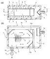
- FIG. 12 shows a ninth embodiment of the separation apparatus of the present invention, in which (a) is a sectional view in the HH direction of (b), and (b) is a sectional view in the II direction of (a). .
- the separation apparatus 1 includes a separation tank 2, a partition plate 5 that partitions the inside of the separation tank 2 into an inflow chamber 3 and an outflow chamber 4, a screen 8 provided on the partition plate 5, and the inflow chamber 3 as a first chamber 30 and a first chamber 30.
- a section 32 divided into two chambers 31, an opening 33 formed in the section 32, a supply section 6 formed in the first chamber 30, and a discharge section 7 formed in the outflow chamber 4 are provided.
- the supply unit 6 is formed by a through hole provided in the side wall of the first chamber 30, and the discharge unit 7 is formed by a through hole provided in the peripheral wall of the outflow chamber 4.
- the supply unit 6 is connected with, for example, a short pipe 6a for connecting to the upstream pipeline of the sewer, and the discharge unit 7 is connected with a short tube 7a for connecting to the downstream pipeline.
- the short pipes 6 a and 7 a may be omitted, and a pipe such as a sewer can be directly connected to the supply unit 6 and the discharge unit 7.
- the separation tank 2 can be made of reinforced concrete, metal, fiber reinforced plastic or the like. As shown in FIG. 12B, the upper part of the separation tank 2 is in an open state, and is closed by an openable / closable lid 34 such as an iron plate during the separation process.
- the inside of the inflow chamber 3 (specifically, the first chamber 30 constituting the inflow chamber 3) and the inside of the outflow chamber 4 communicate with each other at a space portion above them, and the space portion forms an overflow portion 35.
- the overflow part 35 temporarily flows a large amount of floating solids and oil into the inflow chamber side together with rain water in heavy rain, the inflow chamber 3 is made solid by overflowing them into the outflow chamber 4. Etc. to prevent it from being filled and blocked.
- the discharge part 7 is provided with a weir part 7b, which prevents floating solids and oil overflowed by the weir part 7b from flowing out of the discharge part 7 to the downstream side.
- the floating solid substance and oil which have stayed in the outflow chamber 4 can be removed by removing the lid 34 from above at an appropriate time.
- the partition plate 5 on which the screen 8 is arranged partitions the inside of the separation tank 2 into the inflow chamber 3 and the outflow chamber 4 and can be made of a corrosion-resistant metal or fiber reinforced plastic.
- two parallel main surfaces of the partition plate 5 are formed by a frame having a small width, and the screen 8 is disposed inside the frame.
- the screen 8 most of the function of partitioning the inside of the separation tank 2 into the inflow chamber 3 and the outflow chamber 4 is performed by the screen 8.
- the periphery of the partition plate 5 can be fixed to the inner wall of the separation tank 2.
- both ends of the screen 8 having a U-shaped cross section can be directly fixed to the inner wall of the separation tank 2, and in this case, the screen 8 also serves as the partition plate 5.
- the supply unit 6 formed in the first chamber 30 supplies the flowing liquid horizontally from the upper part of the first chamber 30.
- the moving flowing liquid is smoothly lowered, thereby the first chamber 30.
- a guiding portion 9 for smoothly generating a swirling flow in the vertical direction is provided inside.
- the guide portion 9 can be made of a material such as steel, FRP, resin such as polyethylene, concrete, or the like.
- the plate-shaped division body 32 which divides the inflow chamber 3 into the first chamber 30 and the second chamber 31 extends from the side where the supply unit 6 is formed in the inflow chamber 3 to the opposite side. In this way, the first chamber 30 and the second chamber 31 having substantially the same plane area are formed by dividing the inflow chamber 3 into upper and lower portions, and a solid deposit portion is formed using the internal space of the second chamber 31. 36 is formed.
- the partition 32 can be made of a material such as steel, FRP, resin such as polyethylene, concrete, or the like.
- the plate-like section 32 is arranged horizontally when viewed as a whole, but the region on the side where the supply unit 6 is formed and the region on the opposite side (downstream side) are each curved upward in an arc shape.
- the guided portion 9 is formed.
- These guiding units 9 have a function of promoting the generation of a swirling flow in the vertical direction in the first chamber 30 in cooperation with the function of the guiding unit 9 provided above the first chamber 30.
- the screen 8 is perpendicular to the edge of the plate-shaped section 32 in the width direction, that is, two edges facing each other in the direction perpendicular to the axis connecting the supply unit 6 side and the opposite side.
- the lower edge is in contact with the bottom of the second chamber 31.
- An opening 33 for dropping solid matter from the first chamber 30 to the second chamber 31 is formed at the center of the guiding portion 9 on the supply unit 6 side in the partition 32, that is, the center between the two edge portions. ing.
- both edges in the width direction of the opening 33 shown in FIG. 12A are separated from the two edges in the width direction of the section 32, but the present invention is not necessarily limited to this. Both edges in the width direction of 33 can be made to coincide with two edges in the width direction of the section 32.
- the flowing liquid supplied from the supply unit 6 into the first chamber 30 moves in the horizontal direction as shown by the arrow in the upper portion of the first chamber 30, and then is guided by the guide unit 9 to descend. It is guided so as to return in the horizontal direction by the guiding portion 9 (the guiding portion 9 on the right side of FIG. 12B) formed at one end portion, and moves below the supply portion 6 through the lower portion of the first chamber 30. To do.
- the flowing liquid that has moved below the supply unit 6 is guided in the upward direction by the guide unit 9 (the guide unit 9 on the left side of FIG. 12B) formed at the other end of the partition 32. In this way, a swirling flow in the vertical direction is generated in the flowing liquid in the first chamber 30.
- the swirling flow in the vertical direction circulates in the first chamber 30 as described above.
- the upper surface of the swirling flow bundle when flowing in the horizontal direction from the inflow portion 6 is on the downstream side.
- the lower part is guided by the guiding part 9 and returns to the upstream side through the lower part of the first chamber 30 to become the lower surface.
- the lower surface of the swirling flow bundle when flowing in the horizontal direction from the inflow portion 6 is guided and lowered by the downstream guide portion 9 and becomes the upper surface when returning to the upstream side through the lower portion of the first chamber 30.
- the screen 8 is arrange
- the solid matter trapped and adhered to the surface of the screen 8 is efficiently separated by the swirling flow in the vertical direction.
- the separated solid matter such as sand moves in a swirl flow, but most of the solid moves to the second chamber 31 together with a part of the flowing liquid from the opening 33 during the movement, and deposits in the second chamber 31. Deposited in the part 36.
- the flowing liquid flowing into the second chamber 31 passes through the screen 8 extended to the second chamber 31 and flows out to the outflow chamber 4 side.
- the screen 8 provided on the partition plate 5 is arranged along the side surface of the vertical swirling flow formed as described above, and a part of the swirling flow passes through the screen 8 to the outflow chamber 4 side. To do.
- an overflow part 35 As described above, when a large amount of suspended solids and oils temporarily flow into the inflow chamber 3 along with rainwater, they overflow from the overflow portion 35 to the outflow chamber 4 and stay. Yes. Since the floating solids and oil that have overflowed are blocked by the weir part 7b, they do not flow out from the discharge part 7 to the downstream side.
- the amount of solid matter deposited in the deposition portion 36 of the second chamber 31 gradually increases, so that the solid matter deposited by stopping the separation treatment at an appropriate time is deposited.
- the lid 34 covering the upper part of the separation tank 2 is opened, a suction pipe is inserted into the second chamber 31 through the opening 33 from above, and the solid matter deposited on the deposition part 36 by a suction pump or the like is removed. The operation of sucking up and collecting is performed.
- an opening / closing lid is provided below the bottom or side of the second chamber 31, and the deposit is taken out by opening the opening / closing lid.
- the flowing liquid to which the present invention can be applied may include, for example, rainwater flowing into the sewer from houses, roads, and fields, general wastewater, factory wastewater, kitchen wastewater at restaurants, wastewater from meat processing plants, or industrial water.
- the present invention can also be applied to waste oil containing chips and dust such as machine oil and cutting oil, waste water containing waste oil, liquor production waste liquid containing alcohol, and the like.
- waste oil containing chips and dust such as machine oil and cutting oil, waste water containing waste oil, liquor production waste liquid containing alcohol, and the like.
- the present invention can be preferably used for solids separation in many industries.
Landscapes
- Chemical & Material Sciences (AREA)
- Chemical Kinetics & Catalysis (AREA)
- Health & Medical Sciences (AREA)
- Life Sciences & Earth Sciences (AREA)
- Engineering & Computer Science (AREA)
- Hydrology & Water Resources (AREA)
- Public Health (AREA)
- Water Supply & Treatment (AREA)
- Sewage (AREA)
- Filtration Of Liquid (AREA)
- Cyclones (AREA)
Abstract
Description
d 間隙
e 集積部
1 分離装置
2 分離槽
2a 傾斜面
2b 蓋体
3 流入室
4 流出室
5 仕切板
5a オーバーフロー部
6 流入部
6a 短管
7 排出部
7a 短管
7b 堰部
7c 排水路
8 スクリーン、ウェッジワイヤスクリーン
8a ウェッジワイヤ
8b スリット
8c 支持棒
8d 頭部
8e、8f 端部
9、10、10a 誘導部
11 誘導体
12 排出部
13 排液部
12a 開口
12b 蓋体
13a 配管
13b 開閉弁
20 供給部
21 ポンプ
30 第1室
31 第2室
32 区分体
33 開口部
34 蓋体
35 オーバーフロー部
36 堆積部
Claims (13)
- 流入する液体に含まれる固形物を分離する装置において、分離槽と、分離槽の内部を流入室と流出室に仕切る仕切板と、仕切板に設けたスクリーンと、流入室に形成された流入部と、流出室に形成された排出部とを備え、
前記流入室には流入部から流入する液体を反転させて該流入室内に上下方向の旋回流を形成するための誘導部が設けられ、前記スクリーンは前記形成される旋回流の側面に沿うように配置されていることを特徴とする分離装置。 - 請求項1において、前記分離槽は平断面が長軸と短軸を有する方形、楕円形もしくは流入部側が方形で排出部側が円形な方円形に形成され、前記仕切板は長軸方向に平行または偏向して設けられ、前記流入室における流入部は長軸方向の一方の端部に形成され、前記流出室における排出部は長軸方向の他方の端部に形成されていることを特徴とする分離装置。
- 請求項2において、前記スクリーンは2枚設けられ、各スクリーンは互いに平行または流入部から離れるに従ってその間隔が小さくなるように設けられることを特徴とする分離装置。
- 請求項1ないし請求項3のいずれかにおいて、前記スクリーンは断面楔状の複数のウェッジワイヤを上下方向に配列したウェッジワイヤスクリーンで構成され、各ウェッジワイヤの頭部で流入室側の内面の一部が形成されていることを特徴とする分離装置。
- 請求項4において、各ウェッジワイヤの頭部から先端部に向かう軸線が前記形成される上下方向の旋回流の下流側に傾斜しており、前記軸線は上下方向の旋回流における上側流と下側流に応じて互いに逆方向に傾斜していることを特徴とする分離装置。
- 請求項1ないし請求項5のいずれかにおいて、前記流入室の底部に固形物の排出部が設けられていることを特徴とする分離装置。
- 請求項1ないし請求項6のいずれかにおいて、前記流出室の底部に排液部が設けられていることを特徴とする分離装置。
- 請求項1ないし請求項5のいずれかにおいて、前記流入部は流入室の上部に形成され、前記旋回流が流入室内の下部から流入部側に上昇する部分に誘導部が設けられ、該誘導部の先端と前記旋回流が上昇する周壁との間に間隙が設けられていることを特徴とする分離装置。
- 請求項1ないし請求項8のいずれかにおいて、仕切板の上部に流入室と流出室を連通するオーバーフロー部が設けられ、排出部には油分や浮遊性の固形物の流入を防止する堰部が設けられていることを特徴とする分離装置。
- 流入する液体に含まれる固形物を分離する装置において、分離槽と、分離槽の内部を流入室と流出室に仕切る仕切板と、仕切板に設けたスクリーンと、流入室を上側の第1室と下側の第2室に区分する区分体と、区分体に形成された開口部と、第1室に形成された供給部と、流出室に形成された排出部を備え、
前記第1室には供給部から流入する液体の流入方向を反転させて該第1室内に上下方向の旋回流を生成するための誘導部が設けられ、前記スクリーンは前記第1室に形成される上下方向の旋回流の側面に沿うように配置され且つその下縁部が少なくとも区分体まで延長され、第2室に前記開口部から流入する固形物の堆積部が形成されていることを特徴とする分離装置。 - 流入する液体に含まれる固形物を分離する方法において、分離槽と、分離槽の内部を流入室と流出室に仕切る仕切板と、仕切板に設けたスクリーンと、流入室に形成された流入部と、流出室に形成された排出部とを備えた分離装置を用い、流入部から流入する液体を反転させて流入室内に上下方向の旋回流を形成し、前記形成される旋回流の側面に沿うように配置した前記スクリーンで固形物を分離することを特徴とする分離方法。
- 請求項11において、前記スクリーンは断面楔状の複数のウェッジワイヤを上下方向に配列したウェッジワイヤスクリーンで構成され、各ウェッジワイヤの頭部で流入室側の内面の一部が形成されると共に、各ウェッジワイヤの頭部から先端部に向かう軸線が前記形成される上下方向の旋回流の下流側に傾斜していることを特徴とする分離方法。
- 請求項12において、前記分離すべき固形物の平均粒径は10μm~1mmの範囲であることを特徴とする分離方法。
Priority Applications (5)
| Application Number | Priority Date | Filing Date | Title |
|---|---|---|---|
| US12/867,913 US9187890B2 (en) | 2008-02-19 | 2009-02-17 | Separator and separation method |
| EP09712566A EP2251072B1 (en) | 2008-02-19 | 2009-02-17 | Separator and separation method |
| CN2009801057127A CN102089054B (zh) | 2008-02-19 | 2009-02-17 | 分离装置及分离方法 |
| KR1020107005983A KR101157738B1 (ko) | 2008-02-19 | 2009-02-17 | 분리장치 및 분리방법 |
| AU2009216268A AU2009216268B2 (en) | 2008-02-19 | 2009-02-17 | Separator and separation method |
Applications Claiming Priority (2)
| Application Number | Priority Date | Filing Date | Title |
|---|---|---|---|
| JP2008-037163 | 2008-02-19 | ||
| JP2008037163 | 2008-02-19 |
Publications (1)
| Publication Number | Publication Date |
|---|---|
| WO2009104572A1 true WO2009104572A1 (ja) | 2009-08-27 |
Family
ID=40985452
Family Applications (1)
| Application Number | Title | Priority Date | Filing Date |
|---|---|---|---|
| PCT/JP2009/052621 Ceased WO2009104572A1 (ja) | 2008-02-19 | 2009-02-17 | 分離装置及び分離方法 |
Country Status (6)
| Country | Link |
|---|---|
| US (1) | US9187890B2 (ja) |
| EP (1) | EP2251072B1 (ja) |
| JP (1) | JP4395190B2 (ja) |
| KR (1) | KR101157738B1 (ja) |
| CN (1) | CN102089054B (ja) |
| WO (1) | WO2009104572A1 (ja) |
Cited By (3)
| Publication number | Priority date | Publication date | Assignee | Title |
|---|---|---|---|---|
| NL2003551C2 (nl) * | 2009-09-25 | 2011-03-28 | Flamco Bv | Verbeterde afscheider voor microbellen en vuil. |
| US20130228527A1 (en) * | 2010-10-05 | 2013-09-05 | Gross Pollutant Traps Pty Ltd | Filter for polluted water |
| JP7594992B2 (ja) | 2021-10-27 | 2024-12-05 | 水ing株式会社 | 担体分離装置、担体の分離方法および処理システム |
Families Citing this family (36)
| Publication number | Priority date | Publication date | Assignee | Title |
|---|---|---|---|---|
| JP4395190B2 (ja) * | 2008-02-19 | 2010-01-06 | 株式会社ハネックス | 分離装置及び分離方法 |
| JP4668290B2 (ja) * | 2008-04-09 | 2011-04-13 | 株式会社ハネックス | 分離装置 |
| JP4719261B2 (ja) * | 2008-09-16 | 2011-07-06 | 株式会社ハネックス | 分離装置 |
| KR101236215B1 (ko) * | 2011-03-17 | 2013-02-22 | 한국미니맥스 주식회사 | 하천정화장치 |
| KR101275854B1 (ko) | 2011-03-17 | 2013-06-17 | 한국미니맥스 주식회사 | 배수시스템 |
| KR101275853B1 (ko) | 2011-03-17 | 2013-06-17 | 한국미니맥스 주식회사 | 배수시스템 |
| KR101327526B1 (ko) * | 2011-05-25 | 2013-11-08 | 이소라 | 수처리 구조물 |
| ITBO20120046A1 (it) * | 2012-02-02 | 2013-08-03 | Wamgroup Spa | Impianto per la depurazione di acque reflue |
| KR101162500B1 (ko) * | 2012-02-21 | 2012-07-05 | 박태규 | 수처리 장치 |
| WO2014005175A1 (en) * | 2012-07-02 | 2014-01-09 | Leo Crasti | Improved filter for polluted water |
| DE102013213709A1 (de) * | 2013-07-12 | 2015-01-15 | Ksb Aktiengesellschaft | Abwasserhebeanlage |
| US20150129511A1 (en) * | 2013-11-08 | 2015-05-14 | General Electric Company | Dishwasher appliance and a method for operating an appliance |
| EP3023165A1 (de) * | 2014-11-19 | 2016-05-25 | Stocker Mechatronik GmbH | Spaltsieb |
| GB2533001A (en) | 2014-12-04 | 2016-06-08 | Hydro Int Plc | A stormwater filter |
| JP5842049B1 (ja) * | 2014-12-18 | 2016-01-13 | ゼニス羽田株式会社 | 固形物の洗浄装置 |
| CN106039795B (zh) * | 2016-07-24 | 2017-10-27 | 哈尔滨理工大学 | 一种网格宽度连续调节滤网和网格宽度连续调节方法 |
| JP6345754B2 (ja) * | 2016-12-15 | 2018-06-20 | 株式会社日水コン | ごみ分離システム |
| CN108421293B (zh) * | 2017-02-13 | 2023-10-13 | 上海能正渔业科技开发有限公司 | 一种斜筛固液分离器及其使用方法 |
| US10669177B1 (en) * | 2017-06-14 | 2020-06-02 | Stallion Oilfield Services Ltd. | Apparatus and method for recycling blackwater and greywater at oil and gas well sites |
| WO2019220469A1 (de) * | 2018-05-18 | 2019-11-21 | Wild Metal Srl | Feinrechen, der geeignet ist in eine wasserfassung eingebaut zu werden |
| CN108436087A (zh) * | 2018-05-22 | 2018-08-24 | 鑫精合激光科技发展(北京)有限公司 | 一种高速列车保护变压器用滤网及其增材制造方法 |
| JP6619842B2 (ja) * | 2018-05-23 | 2019-12-11 | 株式会社日水コン | ごみ分離システム |
| JP7072776B2 (ja) | 2018-06-28 | 2022-05-23 | ベルテクス株式会社 | 分離装置 |
| KR102101993B1 (ko) * | 2018-07-31 | 2020-04-20 | 주식회사 미래인더스트리 | 유수분리조 |
| US11066798B2 (en) | 2019-06-13 | 2021-07-20 | Sea To Sky Energy Solutions Corp. | Water intake structure |
| KR102127152B1 (ko) * | 2019-12-05 | 2020-06-29 | 주식회사 에이이 | 선회류를 이용한 협잡물 제거장치 |
| JP7429425B2 (ja) * | 2020-01-17 | 2024-02-08 | 四国水道工業株式会社 | 接合井 |
| JP7423414B2 (ja) * | 2020-05-15 | 2024-01-29 | 水ing株式会社 | 担体分離装置、担体分離装置の運転方法、多段担体分離装置、および嫌気性処理装置 |
| AU2021275113A1 (en) * | 2020-05-19 | 2023-01-05 | Johnson Screens, Inc. | Sieve panel having variable tilt screen element |
| GB202017231D0 (en) * | 2020-10-30 | 2020-12-16 | Innsep As | A separator for a multi-phase flow |
| US11459744B2 (en) * | 2021-01-04 | 2022-10-04 | United States Of America As Represented By The Secretary Of The Navy | In-pipe storm water filter |
| JP6984925B1 (ja) * | 2021-02-25 | 2021-12-22 | 株式会社ブンリ | 濾過装置 |
| CN113653147A (zh) * | 2021-08-13 | 2021-11-16 | 中建八局西南建设工程有限公司 | 一种具有抗淤功能的排口监测装置 |
| US20230191290A1 (en) * | 2021-12-21 | 2023-06-22 | 360 Research Labs, LLC | Systems and methods for recycling recovered water utilizing a defluidizing tank |
| JP7233145B1 (ja) * | 2022-09-15 | 2023-03-06 | 株式会社松浦機械製作所 | クーラント処理装置 |
| JP7689400B1 (ja) * | 2024-10-04 | 2025-06-06 | 不二夫 仙波 | 分離装置 |
Citations (6)
| Publication number | Priority date | Publication date | Assignee | Title |
|---|---|---|---|---|
| JPS6028048U (ja) * | 1983-07-30 | 1985-02-25 | 雪下 毅 | ろ過器 |
| JPH06319909A (ja) * | 1993-05-14 | 1994-11-22 | Kubota Corp | 流体中の小粒子分離器 |
| JPH08141326A (ja) | 1994-11-16 | 1996-06-04 | Ishigaki Mech Ind Co | 旋回流を用いた除塵装置 |
| JPH09299974A (ja) * | 1996-05-09 | 1997-11-25 | Nkk Corp | 曝気槽における担体分離用スクリーン装置 |
| JP2000140518A (ja) * | 1998-11-10 | 2000-05-23 | Suiken Kiko:Kk | 固液分離装置 |
| WO2002060554A1 (en) * | 2001-02-01 | 2002-08-08 | Suikenkikou Co., Ltd | Aeration type underwater screen system |
Family Cites Families (45)
| Publication number | Priority date | Publication date | Assignee | Title |
|---|---|---|---|---|
| US1880273A (en) * | 1926-11-30 | 1932-10-04 | Anthracite Separator Co | Coal drier |
| US2672982A (en) * | 1950-12-01 | 1954-03-23 | Way Alben Warren | Solids retention apparatus for streams |
| US4092249A (en) | 1976-06-21 | 1978-05-30 | Commanche Engineering Corp. | Sewage treatment device |
| US4139471A (en) * | 1976-09-07 | 1979-02-13 | Dominick Foti | Sewage treatment unit |
| US4221667A (en) * | 1979-04-12 | 1980-09-09 | Chem-Farm Inc. | Whirlfilter |
| FR2521446B1 (fr) * | 1982-02-15 | 1987-06-05 | Beaudrey & Cie | Filtre a crepine fixe en particulier pour eaux industrielles |
| JPS6028048A (ja) | 1983-07-25 | 1985-02-13 | Matsushita Electric Ind Co Ltd | マスタ−スタンパ−の製造方法 |
| EP0136915A3 (en) * | 1983-10-05 | 1986-03-19 | The Marconi Company Limited | Area weapon simulation |
| SE452558B (sv) * | 1985-05-17 | 1987-12-07 | Sea Parator Hb | Sett och anordning for avskiljning av kroppar ur en vetska |
| FI83864C (fi) * | 1987-03-25 | 1991-09-10 | Oiva Suutarinen | Foerfarande foer renande av en vaetska fraon fasta och upploesta foeroreningar med ett flotationsklarning-flockningsfoerfarande. |
| US5034122A (en) * | 1990-07-20 | 1991-07-23 | Wiesemann Enterprises, Inc. | Self cleaning static bar grid |
| CN1067826A (zh) | 1991-06-15 | 1993-01-13 | 康德拉剪切机支架有限公司 | 筛网条及筛滤装置 |
| DK2393D0 (da) * | 1993-01-11 | 1993-01-11 | Joergen Mosbaek Johannessen | Fordeler- og styreenhed |
| JP3396246B2 (ja) * | 1993-01-18 | 2003-04-14 | 株式会社ナガオカ | 多層コンポジットスクリーン |
| CA2155859C (en) | 1993-02-11 | 2004-08-03 | Paul Blanche | An apparatus for the separation of solids from flowings liquids |
| JP2981960B2 (ja) * | 1993-06-04 | 1999-11-22 | アクアテック株式会社 | 固形物流離分離方法 |
| AUPM628594A0 (en) * | 1994-06-17 | 1994-07-07 | Blanche, Paul | An apparatus for the separation of solids from flowing liquid |
| AU726262B2 (en) | 1994-07-28 | 2000-11-02 | Leslie Richards | Waste treatment apparatus |
| NZ313104A (en) * | 1995-07-28 | 1999-11-29 | Univ Swinburne | Separator |
| AUPN520195A0 (en) * | 1995-09-04 | 1995-09-28 | Bennett, Peter Joseph | Filtering apparatus |
| AUPN817896A0 (en) * | 1996-02-21 | 1996-03-14 | Nicholas, Douglas Ian | Stormwater sediment and litter trap |
| US5770057A (en) * | 1996-08-12 | 1998-06-23 | John Meunier Inc. | Overflow water screening apparatus |
| CA2269615C (en) * | 1996-10-23 | 2006-07-11 | Ecosol Pty Ltd. | Gross pollution filter |
| US5814216A (en) * | 1997-02-07 | 1998-09-29 | John Meunier Inc. | Waste water contaminant segregating unit for sewer conduits |
| US5840180A (en) * | 1997-06-02 | 1998-11-24 | John Meunier Inc. | Water flow segregating unit with endless screw |
| AUPP048197A0 (en) * | 1997-11-21 | 1997-12-18 | University Of South Australia | Stormwater filtration apparatus |
| US6287459B1 (en) * | 1998-04-01 | 2001-09-11 | Remedial Solutions, Inc. | Drainwater treatment system for use in a vertical passageway |
| AUPP418198A0 (en) * | 1998-06-17 | 1998-07-09 | Turco, Eugene | A screening apparatus |
| US6337016B1 (en) * | 1999-03-19 | 2002-01-08 | Mycelx Technologies Corporation | Apparatus for removing noxious contaminants from drainage water |
| AUPQ618400A0 (en) * | 2000-03-13 | 2000-04-06 | Baramy Engineering Pty Ltd | A gross pollutant trap |
| AUPQ746600A0 (en) * | 2000-05-12 | 2000-06-08 | Water Solutions (Aust) Pty Ltd | Solids/liquids separator |
| US6270663B1 (en) * | 2000-07-17 | 2001-08-07 | Henry Happel | Storm drain filter system |
| DE60126292T2 (de) * | 2000-08-29 | 2007-05-31 | Hydro International Plc, Clevedon | Siebanordnung für eine überlaufschwelle für einen schmutzwasserkanal |
| US6651825B2 (en) * | 2001-06-06 | 2003-11-25 | Fresh Creek Technologies, Inc. | Disposable net assemblies for apparatus for collecting floating debris |
| US6478954B1 (en) * | 2001-06-06 | 2002-11-12 | Fresh Creek Technologies, Inc. | Debris collecting apparatus |
| US7138048B1 (en) * | 2002-04-30 | 2006-11-21 | Ch2M Hill, Inc. | Apparatus and method for the removal of solids and floatables from a wastewater stream |
| US6953529B2 (en) * | 2003-05-05 | 2005-10-11 | Weir Robert K | Apparatus and method of particulate removal from liquids |
| US7083721B2 (en) * | 2003-05-12 | 2006-08-01 | Mcclure Stewart D | Stormdrain curb-inlet multi-stage filtration-unit |
| US7258785B2 (en) * | 2003-10-07 | 2007-08-21 | Weir Robert K | Apparatus for separating oil and debris from water run-off |
| CN2707347Y (zh) | 2004-06-18 | 2005-07-06 | 张富成 | 条状缝隙滤网 |
| US7294256B2 (en) * | 2005-01-24 | 2007-11-13 | Henry Happel | Storm water filter system |
| US7465391B2 (en) * | 2005-09-09 | 2008-12-16 | Cds Technologies, Inc. | Apparatus for separating solids from flowing liquids |
| GB2443678B (en) * | 2006-11-07 | 2011-05-11 | Jonathan Owen | Filter trap for waste water |
| US8034234B2 (en) * | 2007-12-27 | 2011-10-11 | Happel Thomas H | Floating skimmer apparatus with up-flow filter |
| JP4395190B2 (ja) * | 2008-02-19 | 2010-01-06 | 株式会社ハネックス | 分離装置及び分離方法 |
-
2008
- 2008-10-03 JP JP2008257981A patent/JP4395190B2/ja active Active
-
2009
- 2009-02-17 US US12/867,913 patent/US9187890B2/en active Active
- 2009-02-17 WO PCT/JP2009/052621 patent/WO2009104572A1/ja not_active Ceased
- 2009-02-17 EP EP09712566A patent/EP2251072B1/en not_active Not-in-force
- 2009-02-17 CN CN2009801057127A patent/CN102089054B/zh not_active Expired - Fee Related
- 2009-02-17 KR KR1020107005983A patent/KR101157738B1/ko not_active Expired - Fee Related
Patent Citations (6)
| Publication number | Priority date | Publication date | Assignee | Title |
|---|---|---|---|---|
| JPS6028048U (ja) * | 1983-07-30 | 1985-02-25 | 雪下 毅 | ろ過器 |
| JPH06319909A (ja) * | 1993-05-14 | 1994-11-22 | Kubota Corp | 流体中の小粒子分離器 |
| JPH08141326A (ja) | 1994-11-16 | 1996-06-04 | Ishigaki Mech Ind Co | 旋回流を用いた除塵装置 |
| JPH09299974A (ja) * | 1996-05-09 | 1997-11-25 | Nkk Corp | 曝気槽における担体分離用スクリーン装置 |
| JP2000140518A (ja) * | 1998-11-10 | 2000-05-23 | Suiken Kiko:Kk | 固液分離装置 |
| WO2002060554A1 (en) * | 2001-02-01 | 2002-08-08 | Suikenkikou Co., Ltd | Aeration type underwater screen system |
Non-Patent Citations (1)
| Title |
|---|
| See also references of EP2251072A4 * |
Cited By (5)
| Publication number | Priority date | Publication date | Assignee | Title |
|---|---|---|---|---|
| NL2003551C2 (nl) * | 2009-09-25 | 2011-03-28 | Flamco Bv | Verbeterde afscheider voor microbellen en vuil. |
| WO2011037465A1 (en) * | 2009-09-25 | 2011-03-31 | Flamco B.V. | Improved removal device for micro-bubbles and dirt |
| US8790446B2 (en) | 2009-09-25 | 2014-07-29 | Flamco B.V. | Removal device for micro-bubbles and dirt |
| US20130228527A1 (en) * | 2010-10-05 | 2013-09-05 | Gross Pollutant Traps Pty Ltd | Filter for polluted water |
| JP7594992B2 (ja) | 2021-10-27 | 2024-12-05 | 水ing株式会社 | 担体分離装置、担体の分離方法および処理システム |
Also Published As
| Publication number | Publication date |
|---|---|
| KR20100051103A (ko) | 2010-05-14 |
| JP2009220096A (ja) | 2009-10-01 |
| EP2251072A4 (en) | 2011-04-13 |
| US9187890B2 (en) | 2015-11-17 |
| EP2251072A1 (en) | 2010-11-17 |
| JP4395190B2 (ja) | 2010-01-06 |
| AU2009216268A1 (en) | 2009-08-27 |
| CN102089054B (zh) | 2013-10-16 |
| US20110000862A1 (en) | 2011-01-06 |
| CN102089054A (zh) | 2011-06-08 |
| KR101157738B1 (ko) | 2012-06-25 |
| EP2251072B1 (en) | 2012-07-11 |
Similar Documents
| Publication | Publication Date | Title |
|---|---|---|
| JP4395190B2 (ja) | 分離装置及び分離方法 | |
| US12385243B2 (en) | Multi-component weir controlled hydrodynamic separator for stormwater treatment | |
| US7892425B2 (en) | Stormwater plug flow separation system | |
| EP2755736B1 (en) | Fluid treatment apparatus, system, and methods | |
| US7722763B2 (en) | Purification and separation system for a fluid flow stream | |
| JP4729590B2 (ja) | 分離装置 | |
| JP4751910B2 (ja) | 分離装置及び分離方法 | |
| JP4729589B2 (ja) | 分離装置 | |
| JP4719261B2 (ja) | 分離装置 | |
| US10662637B2 (en) | Inclined plates for CSO | |
| US10052570B2 (en) | Settling basin insert | |
| US7507333B2 (en) | Method of and apparatus for cleaning runoff water | |
| JP4685891B2 (ja) | 分離装置 | |
| KR100804078B1 (ko) | 스크린 여과와 원심력을 이용한 비점오염원 제거장치 | |
| JP4668290B2 (ja) | 分離装置 | |
| JP2008284425A (ja) | 排水分離装置 | |
| JP4701258B2 (ja) | 分離装置 | |
| KR100649180B1 (ko) | 경사판 침전을 이용한 초기우수(비점오염원) 및 하수관거월류수 처리장치 | |
| JP4673923B2 (ja) | 液体処理装置 | |
| EP4286027A1 (en) | Hydrodynamic separator | |
| KR200424846Y1 (ko) | 경사판 침전을 이용한 초기우수(비점오염원) 및 하수관거월류수 처리장치 | |
| JP2014180615A (ja) | 固体分離装置及び固体分離方法 | |
| RU216201U1 (ru) | Устройство для очистки сточных вод | |
| KR100900053B1 (ko) | 비점오염원 처리장치 | |
| US20150159360A1 (en) | System and method for minimizing sediment accumulation in pond inlets |
Legal Events
| Date | Code | Title | Description |
|---|---|---|---|
| WWE | Wipo information: entry into national phase |
Ref document number: 200980105712.7 Country of ref document: CN |
|
| 121 | Ep: the epo has been informed by wipo that ep was designated in this application |
Ref document number: 09712566 Country of ref document: EP Kind code of ref document: A1 |
|
| ENP | Entry into the national phase |
Ref document number: 20107005983 Country of ref document: KR Kind code of ref document: A |
|
| WWE | Wipo information: entry into national phase |
Ref document number: 2009216268 Country of ref document: AU Ref document number: 5818/DELNP/2010 Country of ref document: IN |
|
| NENP | Non-entry into the national phase |
Ref country code: DE |
|
| WWE | Wipo information: entry into national phase |
Ref document number: 2009712566 Country of ref document: EP |
|
| ENP | Entry into the national phase |
Ref document number: 2009216268 Country of ref document: AU Date of ref document: 20090217 Kind code of ref document: A |
|
| WWE | Wipo information: entry into national phase |
Ref document number: 12867913 Country of ref document: US |