WO2009099081A1 - 通信装置、通信方法、及び、プログラム - Google Patents
通信装置、通信方法、及び、プログラム Download PDFInfo
- Publication number
- WO2009099081A1 WO2009099081A1 PCT/JP2009/051837 JP2009051837W WO2009099081A1 WO 2009099081 A1 WO2009099081 A1 WO 2009099081A1 JP 2009051837 W JP2009051837 W JP 2009051837W WO 2009099081 A1 WO2009099081 A1 WO 2009099081A1
- Authority
- WO
- WIPO (PCT)
- Prior art keywords
- unit
- light
- communication device
- image
- instruction
- Prior art date
- Legal status (The legal status is an assumption and is not a legal conclusion. Google has not performed a legal analysis and makes no representation as to the accuracy of the status listed.)
- Ceased
Links
Images


Classifications
-
- G—PHYSICS
- G06—COMPUTING OR CALCULATING; COUNTING
- G06Q—INFORMATION AND COMMUNICATION TECHNOLOGY [ICT] SPECIALLY ADAPTED FOR ADMINISTRATIVE, COMMERCIAL, FINANCIAL, MANAGERIAL OR SUPERVISORY PURPOSES; SYSTEMS OR METHODS SPECIALLY ADAPTED FOR ADMINISTRATIVE, COMMERCIAL, FINANCIAL, MANAGERIAL OR SUPERVISORY PURPOSES, NOT OTHERWISE PROVIDED FOR
- G06Q50/00—Information and communication technology [ICT] specially adapted for implementation of business processes of specific business sectors, e.g. utilities or tourism
- G06Q50/10—Services
- G06Q50/12—Hotels or restaurants
-
- G—PHYSICS
- G06—COMPUTING OR CALCULATING; COUNTING
- G06Q—INFORMATION AND COMMUNICATION TECHNOLOGY [ICT] SPECIALLY ADAPTED FOR ADMINISTRATIVE, COMMERCIAL, FINANCIAL, MANAGERIAL OR SUPERVISORY PURPOSES; SYSTEMS OR METHODS SPECIALLY ADAPTED FOR ADMINISTRATIVE, COMMERCIAL, FINANCIAL, MANAGERIAL OR SUPERVISORY PURPOSES, NOT OTHERWISE PROVIDED FOR
- G06Q10/00—Administration; Management
- G06Q10/10—Office automation; Time management
Definitions
- the present invention relates to a communication device, a communication method, and a program, and more particularly, to a communication device, a communication method, and a program that enable the whole city to prosper.
- a medical mall there are a plurality of medical facilities, that is, for example, specialized medical facilities such as ophthalmology, internal medicine, and surgery. People living in a city as a medical mall do not go to other cities. However, in the city as the medical mall, you can receive various specialized medical treatments.
- a plurality of hotels are arranged as a plurality of facilities providing similar services, and services such as provision of food and drinks and accommodation facilities are provided.
- each of a plurality of hotels in a hot spring town is in a state of competition with other hotels, so efforts are made to attract customers individually.
- a technique for performing daylighting described in Patent Document 1 can be used.
- scenery for example, a technique for selectively displaying images taken by a plurality of remote cameras described in Patent Document 2 can be used to provide various images to customers (users) as scenery. Can show.
- Patent Documents 1 and 2 there is no description or suggestion of realizing cooperation in which a plurality of facilities cooperate.
- the present invention has been made in view of such a situation, and realizes cooperation in which a plurality of facilities having similar purposes in close cooperation cooperate, thereby enabling the prosperity of the entire city.
- the communication apparatus senses a physical quantity and outputs the physical quantity to send the physical quantity to another communication apparatus, and an instruction to instruct the sensor output of the sensor means included in the other communication apparatus And a receiving unit that receives a sensor output of the sensor unit that is instructed in accordance with the instruction information.
- the communication method includes a sensor unit that senses a physical quantity and outputs the physical quantity to send the physical quantity to another communication apparatus, senses the physical quantity, Sensor means for outputting to another communication apparatus, instructing sensor output of sensor means included in the other communication apparatus, transmitting instruction information corresponding to the instruction, and instructing according to the instruction information It is a communication method including the step which receives the sensor output of this.
- the program according to one aspect of the present invention includes a sensor unit that senses a physical quantity and outputs the physical quantity to output to another communication apparatus.
- a sensor unit that senses a physical quantity and outputs the physical quantity to send to another communication device is sensed and the physical quantity is sent to the other communication device. Is output for On the other hand, the sensor output instruction of the sensor means included in the other communication apparatus is instructed, and instruction information corresponding to the instruction is transmitted. And the sensor output of the sensor means instructed according to the instruction information is received.
- the communication device may be an independent device or an internal block constituting one device.
- the program can be provided by being transmitted through a transmission medium or by being recorded on a recording medium.
- FIG. 3 It is a figure which shows the example of the town where the cooperation processing system for implement
- FIG. 3 It is a block diagram which shows the structural example of the cooperation processing system installed in the town of FIG. 3 is a flowchart for explaining processing of the communication device 11.
- 3 is a flowchart illustrating processing of a control device 103.
- It is a block diagram which shows the 2nd structural example of the cooperation processing system applied to the town of FIG. 3 is a flowchart illustrating processing of the communication apparatus 101.
- 3 is a flowchart illustrating processing of a control device 103.
- FIG. 311 It is sectional drawing which shows the structural example of guest room HA1 in which the communication apparatus 301 was installed. It is a figure which shows the structural example of the sunlight lighting apparatus used as the condensing part 311. FIG. It is a figure which shows the detailed structural example of the sunlight lighting apparatus 380. FIG. It is sectional drawing which shows the structural example of the lighting part 345. FIG. It is a figure which shows the other structural example of the lighting part. It is a figure explaining the operation mode of the light distribution part. It is a flowchart explaining the process of a cooperation processing system. It is a block diagram which shows the 5th structural example of the cooperation processing system applied to the town of FIG. It is a figure explaining the process of a cooperation processing system.
- FIG. 1 shows a configuration example of an embodiment of a collaborative processing system for realizing a collaboration in which a plurality of facilities cooperate with each other, to which the present invention is applied.
- the collaborative processing system includes a plurality of, for example, two communication devices 11 and 12 and a control device 13.
- the collaborative processing system is installed in a town where a plurality of facilities having the same purpose exist, such as a hot spring town and a town where casino facilities are gathered.
- the town where the collaborative processing system is installed may be a town in which a visitor does not permanently reside such as a hot spring town, or a town intended for permanent residence such as a medical mall.
- FIG. 1 there are two facilities i1 and i2 (providing similar services) for the same purpose and a control center in the city, the communication device 11 in the facility i1, and the communication device in the facility i2. 12 and a control device 13 are installed in the control center.
- the communication device 11 of the facility i1 and the communication device 12 of the facility i2 perform communication for cooperation with the control device 13 of the control center, and perform processing according to the control of the control device 13 and the like.
- control device 13 can be installed in the facility i1 or i2 in an integrated manner with the communication device 11 or 12 instead of the control center.
- the facility i1 or i2 in which the control device 13 is installed also functions as a control center.
- control device 13 can be shared by the communication devices 11 and 12, and in this case, the facilities i1 and i2 also function as a control center.
- the collaborative processing system includes two communication devices 11 and 12, but the collaborative processing system can be provided with three or more communication devices.
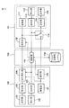
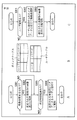
- FIG. 2 shows a configuration example of a collaborative processing system installed in the city of FIG.
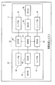
- the communication device 11 includes a sensor unit 31, an instruction unit 32, a transmission unit 33, and a receiving unit 34.
- the sensor unit 31 senses a physical quantity such as light, and outputs the physical quantity to be sent to another communication device 12 or the like.
- the output (sensor output) of the sensor unit 31 is supplied to the sending unit 52.
- the instruction unit 32 instructs, for example, the sensor output of the sensor unit 41 included in the other communication device 12 according to the user's operation or the like. That is, the instruction unit 32 generates instruction information corresponding to an instruction such as a sensor output of the sensor unit 41 included in the other communication device 12 in accordance with a user operation or the like, and supplies the instruction information to the transmission unit 33.
- the transmission unit 33 transmits instruction information from the instruction unit 32 to the control unit 51.
- the receiving unit 34 receives a sensor output instructed according to the instruction information transmitted to the control unit 51, for example, from the sending unit 53.
- the communication device 12 is configured in the same manner as the communication device 11.
- the communication device 12 includes a sensor unit 41, an instruction unit 42, a transmission unit 43, and a receive unit 44 similar to the sensor unit 31, the instruction unit 32, the transmission unit 33, and the receive unit 34, respectively.
- the sensor output of the sensor unit 41 is supplied to the sending unit 53.
- the receiving part 44 receives the sensor output from the sending part 52, when the sensor output instruct
- the control device 13 includes a control unit 51 and sending units 52 and 53.
- the control unit 51 receives instruction information transmitted from the transmission unit 33 of the communication device 11, instruction information transmitted from the transmission unit 43 of the communication device 12, and transmission units of other communication devices constituting the collaborative processing system. In accordance with the transmitted instruction information, provision of sensor output by the sending units 52 and 53 is controlled.
- the sending unit 52 outputs the sensor output of the sensor unit 31 of the communication device 11 to another communication device (for example, the communication device 12 or other communication device constituting the collaborative processing system) according to the control of the control unit 51. ).
- the sending unit 53 sends the sensor output of the sensor unit 41 of the communication device 12 to another communication device (for example, the communication device 11 or other communication device constituting the collaborative processing system) according to the control of the control unit 51. ) To provide.
- the sending unit 52 that provides the sensor output of the sensor unit 31 of the communication device 11 to another communication device can be provided in the communication device 11 instead of the control device 13.
- the sending unit 53 that provides the sensor output of the sensor unit 41 of the communication device 12 to another communication device can be provided in the communication device 12 instead of the control device 13.
- processing similar to that performed by the communication device 11 is also performed by other communication devices including the communication device 12 that constitute the collaborative processing system.
- the first and second processes are performed.
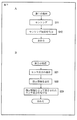
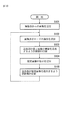
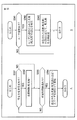
- FIG. 3A is a flowchart for explaining the first processing.
- step S11 the sensor unit 31 senses a physical quantity such as light, and the process proceeds to step S12.
- step S12 the sensor unit 31 outputs a sensing result obtained by sensing a physical quantity as a sensor output.
- the sensor output of the sensor unit 31 is supplied to the sending unit 52.
- FIG. 3B is a flowchart for explaining the second process.
- step S21 the instruction unit 32 instructs the sensor output or the like of another communication device in accordance with a user operation or the like. That is, for example, the instruction unit 32 generates instruction information corresponding to an instruction such as sensor output of the sensor unit 41 included in the communication device 12 and supplies the instruction information to the transmission unit 33, and the process proceeds from step S21 to step S22. .
- step S22 the transmission unit 33 transmits the instruction information from the instruction unit 32 to the control unit 51, and the process proceeds to step S23.
- step S23 the receiving unit 34 receives a sensor output instructed in accordance with the instruction information transmitted from the transmitting unit 33 to the control unit 51.
- control unit 51 receives the instruction information and provides a sensor output to the communication device 11 according to the instruction information. Take control.
- the control unit 51 detects the sensor of the sensor unit 41 of the communication device 12.
- the sending unit 53 is caused to provide the sensor device 41 with the sensor output of the sensor unit 41.
- step S23 the receiving unit 34 receives the sensor output provided from the sending unit 53, for example, as described above.
- FIG. 4 shows an example of a town where a collaborative processing system is installed.
- the town shown in FIG. 4 is, for example, a town as a resort area, and four hotels HA, HB, HC, and HD and a control center are constructed.
- Hotel HA has multiple guest rooms HA1, HA2, ....
- the hotel HB has a plurality of guest rooms HB1, HB2,...
- the hotel HC has a plurality of guest rooms HC1, HC2,...
- the hotel HD has a plurality of guest rooms HD1, HD2,. ⁇ ⁇ Are provided.
- Hotel HA (rooms HA1, HA2, ...) is built in a position where you can see the actual mountain view, and Hotel HB is built in a position where you can see the actual river view. ing.
- Hotel HC is constructed in a position where the actual sea view can be seen, and Hotel HD is constructed in a position where the actual city view can be seen.
- Hotel HA is the actual scenery that can be seen from other hotels, that is, the actual river view that can be seen from Hotel HB, the actual sea view that can be seen from Hotel HC, and It is in a location where you cannot see the actual city view from Hotel HD.
- Hotel HB is also the actual mountain view that can be viewed from Hotel HA, the actual sea view that can be viewed from Hotel HC, and the actual city view that can be viewed from Hotel HD. It is a location that cannot be seen.
- Hotel HC is also the actual mountain view that can be seen from Hotel HA, the actual river view that can be seen from Hotel HB, and the actual city view that can be seen from Hotel HD.
- the location where you can not see the scenery, the location of Hotel HD, the actual mountain view that can be seen from Hotel HA, the actual river view that can be seen from Hotel HB, and the view from Hotel HC The location is such that you can not see the actual sea view.
- the collaborative processing system installed in the city, through the collaborative processing, in either of the hotel HA or HD (in the guest room), the mountain scenery that would have been able to be seen if staying at the hotel HA, the hotel The view of the river you could have seen if you stayed at the HB, the view of the sea that you could have seen if you stayed at the Hotel HC, and the view of the river if you stayed at the Hotel HD You can see any of the scenery of the Deaf City.
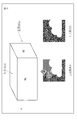
- FIG. 5 schematically shows a configuration example of the guest room HA1 of the hotel HA.
- the wall surface on which the actual mountain scenery can be viewed is the display unit 115.
- the entire wall surface may be the display unit 115, or a part of the wall surface may be the display unit 115.
- a part of the wall surface is used as the display unit 115, for example, a part of the wall surface that originally becomes a window can be used as the display unit 115.
- the wall surface used as the display unit 115 is not limited to one wall surface on which the actual mountain scenery can be seen, but the other wall surface may be the same display unit as the display unit 115. it can.
- the wall surface of the guest room HA1 from which the actual mountain scenery can be seen is the display unit 115, and the display unit 115 is used.
- This wall is also called a display wall.
- the display unit 115 displays an image, and is installed so that the display surface for displaying the image is on the indoor side of the guest room HA1.
- the display unit 115 can display an image and can be transparent.
- the operation modes of the display unit 115 include an image display mode and a transparent mode.
- a mode in which the display unit 115 displays an image as appropriate is referred to as an image display mode
- a mode in which the display unit 115 is transparent is referred to as a window mode.
- the display unit 115 In the window mode, since the display unit 115 becomes transparent, as shown in FIG. 5A, an actual mountain scenery can be viewed from the guest room HA1 through the transparent display unit 115. Therefore, in the window mode, the display unit 115 functions as a window.
- the display unit 115 displays an image taken by a camera or the like.
- an imaging unit 111 that captures an image and outputs an image signal, such as a camera, is installed on the back surface of the display unit 115 (display wall surface).
- the back surface of the display unit 115 is a surface on the back side of the front surface when a display surface on which an image is displayed is the front surface.
- the imaging unit 111 may be installed at a position where it is possible to capture a scene image that can be seen from the room HA1.
- it may be installed at a position near the display unit 115 on the back side of the display unit 115.
- a position close to the display unit 115 on the back surface of the display unit 115 and the back side of the display unit 115 is referred to as a substantially back surface of the display unit 115 as appropriate.
- the display unit 115 can display an image corresponding to an image signal obtained as a result of the imaging unit 111 performing imaging. Further, the display unit 115 can display other images.
- guest rooms other than guest room HA1 that is, guest rooms of hotel HA other than guest room HA1, and guest rooms of hotel HB to HD that are different from hotel HA are also configured in the same manner as guest room HA1 and are imaged.
- the image capturing unit similar to the unit 111 and the display unit similar to the display unit 115 are provided, and the image capturing unit is disposed almost on the back of the display unit.
- the image pickup unit is installed in a direction in which an actual scenery that can be viewed from the hotel HA can be picked up.
- the image pickup unit of the guest room HA1 of the hotel HA faces the image pickup unit of the hotel HB or HD. It is installed in a direction different from the direction in which it is located (imaging direction).
- an image captured by the imaging unit of the guest room of the hotel HA other than the guest room HA1 or the imaging unit of each guest room of the hotel HB or HD is displayed in accordance with, for example, an operation of a guest (user) of the guest room HA1. Can be displayed.
- the user can view a mountain view similar to viewing an actual mountain view in the window mode.
- the display unit 115 for example, as shown in FIG. 5B, when an image captured by any of the imaging units in the guest room of the hotel HB is displayed, the user stays in the hotel HB. If you don't, you can see the river scenery that you could't see, and you can enjoy the feeling of staying at Hotel HB.
- the display unit 115 for example, as shown in FIG. 5C, when an image captured by any imaging unit in the guest room of the hotel HC is displayed, the user stays at the hotel HC. You can see the sea view that you could't see without it, and you can enjoy the feeling of staying at Hotel HC.
- users can stay in any of the hotels HA or HD by realizing cooperation in which each of the hotels HA or HD cooperates and provides images of scenery that can be viewed from each other. Even so, you can see any of the scenery that you can see from each of the hotels HA or HD.
- both the hotels HA and HD can exhibit the same ability to attract customers, and as a result, the entire city can be developed.
- the display unit 115 displays an image picked up by the image pickup unit of the guest room of the hotel HB or HD different from the hotel HA, and has been picked up by the image pickup unit of the guest room of the hotel HA other than the guest room HA1. An image can be displayed.
- the display unit 115 is installed at a position different in height from the imaging unit of a guest room on a floor different from the floor of the guest room HA1, that is, the position where the imaging unit 111 of the guest room HA1 is installed.
- An image captured by the image capturing unit can be displayed.
- the display unit 115 can display an image picked up by the image pickup unit of the guest room on the top floor.
- the user staying in the guest room HA1 on the lower floor can enjoy the feeling as if staying in the guest room on the top floor.
- the display unit 115 can display an image captured by the imaging unit of the guest room of the hotel HA other than the guest room HA1.
- the display unit 115 can display an image captured by the imaging unit of the guest room in the corner room.
- the user staying in the guest room HA1 that is not a corner room can enjoy a feeling as if the user is staying in the guest room of the corner room.
- the angle of view (viewing angle) of the image is such that the user and the display wall surface can enjoy the feeling as if the user is looking at the actual scenery.
- the imaging unit 111 for example, an omnidirectional mirror using a hyperboloidal mirror can be employed.
- the installation of the imaging unit in addition to installing one imaging unit for each guest room, installing a plurality of imaging units in one guest room, for example, a plurality of adjacent two guest rooms, etc. It is possible to install one image pickup unit in a guest room (a plurality of guest rooms also serve as one image pickup unit).
- the display unit 115 for example, a liquid crystal display device that performs display using liquid crystal described in Japanese Patent Application Laid-Open No. 06-043478 can be used.
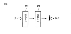
- FIG. 6 shows a configuration example of a liquid crystal display device used as the display unit 115.
- the liquid crystal display device includes two liquid crystal cells 151 and 152.
- the liquid crystal cell 151 changes its state between a light scattering state that scatters light, such as ground glass, and a light transmissive state that transmits light, such as transparent glass, by applying a voltage, for example.
- the liquid crystal cell 152 changes state between a light transmission state and a light shielding state that blocks light by applying a voltage, for example.
- the liquid crystal cell 152 has a function similar to that of a liquid crystal cell employed in a so-called liquid crystal TV (Television), and thus can control light passage (blocking) in units of pixels.
- liquid crystal cell 152 side is a display surface (front surface) on which an image is displayed
- liquid crystal cell 151 side is the back surface of the back side.
- the liquid crystal display device used as the display unit 115 is arranged with the liquid crystal cell 152 facing the indoor side of the guest room HA1 and the liquid crystal cell 151 facing the outdoor side of the guest room HA1 (outside the hotel HA).
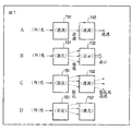
- the liquid crystal display device of FIG. 6 is in four states, a first, a second, a third, and a fourth.
- FIG. 7 shows the first to fourth states of the liquid crystal display device of FIG.
- the liquid crystal cells 151 and 152 are in a light transmission state, and the liquid crystal cell 151 side can be viewed from the liquid crystal cell 152 side.
- the liquid crystal cell 151 is in a light scattering state
- the liquid crystal cell 152 is in a light transmission state or a light shielding state in units of pixels according to an image signal.
- the liquid crystal cell 152 is in a light transmission state or a light shielding state in units of pixels according to the image signal, so that an image corresponding to the image signal is displayed using the scattered light from the liquid crystal cell 151 as a backlight. .
- the liquid crystal cell 151 is in a light scattering state, and the liquid crystal cell 152 is in a light transmission state.
- the liquid crystal display device functions as an illumination device that illuminates the interior of the cabin HA1.
- the liquid crystal cell 152 is in a light shielding state, and the liquid crystal display device functions as a curtain, a shutter, or the like that shields light from the outside.
- the liquid crystal cell 151 may be in either a light scattering state or a light transmission state.
- the cabin HA1 The brightness of the interior of the room can be adjusted.
- the liquid crystal display device used as the display unit 115 is in the first state in the window mode.
- the liquid crystal display device used as the display unit 115 is in the second state in the image display mode and displays an image.
- a projector that displays an image using the display wall surface as a screen can be adopted as the display unit 115.
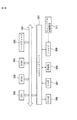
- FIG. 8 shows a first configuration example of the collaborative processing system applied to the town of FIG.
- the collaborative processing system includes a plurality of communication devices 101 and 102 and a control device 103.
- the communication device 101 is installed in the guest room HA1 of the hotel HA, and the communication device 102 is one of other guest rooms other than the guest room HA1, for example, installed in the guest room HB1 (FIG. 4) of the hotel HB. Yes.
- the same communication devices as the communication devices 101 and 102 are installed in the guest rooms of the hotel HA other than the guest room HA1, the guest rooms of the hotel HB other than the guest room HB1, the guest rooms of the hotel HC, and the guest rooms of the hotel HD.
- the explanation is omitted.
- control device 103 can be installed in a control center independent of the hotel HA or HD, or can be installed in the hotel HA or HB, for example, integrated with the communication device 101 or 102.
- control device 103 can be shared by the communication devices 101 and 102 and other communication devices constituting the collaborative processing system.
- the communication apparatus 101 includes an imaging unit 111, an instruction unit 112, a transmission unit 113, a reception unit 114, a display unit 115, and a switching unit 116.
- the imaging unit 111 corresponds to the sensor unit 31 in FIG.
- the imaging unit 111 captures an image (senses light) and outputs an image signal (first image signal). Note that the image signal output by the imaging unit 111 is supplied to the switching unit 116 and the sending unit 132.
- the instruction unit 112 corresponds to the instruction unit 32 in FIG.
- the instruction unit 112 instructs, for example, an image signal (second image signal) output from an imaging unit of another communication device, such as the imaging unit 121 of the communication device 102, according to a user operation or the like. That is, the instruction unit 112 generates instruction information corresponding to an instruction such as an image signal output by the imaging unit of another communication apparatus in accordance with a user operation or the like, and supplies the instruction information to the transmission unit 113.
- the instruction unit 112 generates instruction information representing a necessary instruction according to a user operation or the like, and supplies the instruction information to the transmission unit 113.
- the transmission unit 113 corresponds to the transmission unit 33 in FIG.
- the transmission unit 113 transmits the instruction information from the instruction unit 112 to the control unit 131 and supplies the instruction information to the switching unit 116.
- the receiving unit 114 corresponds to the receiving unit 34 in FIG.
- the receiving unit 114 outputs an image signal output from the imaging unit of another communication device, that is, an image output from the imaging unit 121 of the communication device 102 and transmitted via the sending unit 133 and the switching unit 116, for example.
- the signal is received and supplied to the display unit 115.
- reception unit 114 receives the image signal output from the imaging unit 111 via the switching unit 116 and supplies the image signal to the display unit 115.
- the display unit 115 displays an image signal from the reception unit 114, that is, an image signal output from the imaging unit of another communication apparatus or an image corresponding to the image signal output from the imaging unit 111.
- the switching unit 116 selects an image signal output by the imaging unit of another communication apparatus or an image signal output by the imaging unit 111 according to the instruction information from the transmission unit 113 and supplies the image signal to the reception unit 114.
- the switching unit 116 is supplied with an image signal output from the imaging unit 111 and an image signal output from the imaging unit of another communication device, such as an image signal output from the imaging unit 121 of the communication device 102. Is done.
- instruction information is supplied from the transmission unit 113 to the switching unit 116.
- the instruction information from the transmission unit 113 represents an instruction of an image signal of an image to be displayed on the display unit 115, and the switching unit 116 outputs an image output by the imaging unit of another communication device according to the instruction information.
- a signal or an image signal output from the imaging unit 111 is selected and supplied to the receiving unit 114.
- the image signal output by the imaging unit 121 of the communication device 102 among the image signals output by the imaging units of other communication devices is transmitted from the transmission unit 133. It has become.
- the communication device 102 is configured similarly to the communication device 101.
- the communication apparatus 102 includes an imaging unit 121, an instruction unit 122, a transmission unit 123, and a reception unit similar to the imaging unit 111, the instruction unit 112, the transmission unit 113, the reception unit 114, the display unit 115, and the switching unit 116, respectively. 124, a display unit 125, and a switching unit 126.
- an image signal as a sensor output of the imaging unit 121 is supplied to the transmission unit 133.
- the image signal output from the imaging unit 111 of the communication apparatus 101 among the image signals output from the imaging units of other communication devices is transmitted from the transmission unit 132 to the switching unit 126. It has become.
- the control device 103 includes a control unit 131, sending units 132 and 133, and a storage unit 134.
- the control unit 131 corresponds to the control unit 51 in FIG.
- the control unit 131 follows the instruction information transmitted from the transmission unit 113 of the communication apparatus 101, the instruction information transmitted from the transmission unit 123 of the communication apparatus 102, and the information stored in the storage unit 134 according to the information stored in the storage unit 134.
- the provision of image signals as sensor outputs by the sending units 132 and 133 is controlled.
- the sending unit 132 corresponds to the sending unit 52 in FIG.
- the sending unit 132 configures another communication device (for example, the communication device 102 or a collaborative processing system) for the communication device 101 with the image signal as the sensor output of the imaging unit 111 of the communication device 101 under the control of the control unit 131. Provide (send) to other communication devices.
- another communication device for example, the communication device 102 or a collaborative processing system
- the sending unit 133 corresponds to the sending unit 53 in FIG.
- the sending unit 133 sends the sensor output of the imaging unit 121 of the communication device 102 to another communication device (for example, the communication device 101 or other communication device constituting the collaborative processing system) according to the control of the control unit 131. ) To provide.
- the storage unit 134 stores information necessary for the control unit 131 to perform processing.
- the sending unit 132 that provides an image signal output from the imaging unit 111 of the communication device 101 to another communication device can be provided in the communication device 101 instead of the control device 103.
- the sending unit 133 that provides an image signal output from the imaging unit 121 of the communication device 102 to another communication device can be provided in the communication device 102 instead of the control device 103.
- processing similar to that performed by the communication apparatus 101 is also performed by other communication apparatuses that form the collaborative processing system including the communication apparatus 102.
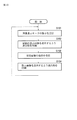
- FIG. 9A is a flowchart for explaining processing of the communication apparatus 101 in FIG.
- step S101 the imaging unit 111 starts capturing an image and outputting an image signal to the sending unit 132, and the process proceeds to step S102.
- the sending unit 132 receives the image signal from the imaging unit 111 and temporarily stores it in a built-in memory (not shown) as necessary. Furthermore, the sending unit 132 transmits the image signal (including the image signal stored in the built-in memory) from the imaging unit 111 to another communication device such as the communication device 102 according to the control of the control unit 131.
- step S102 the display unit 115 sets the operation mode to the window mode, and the process proceeds to step S103. That is, the display unit 115 sets the default operation mode to the window mode.
- step S103 the instruction unit 112 determines whether or not the user of the guest room HA1 (FIG. 4) of the hotel HA in which the communication device 101 is installed has operated the operation mode to be the image display mode.
- step S103 If it is determined in step S103 that the user has not performed an operation so that the operation mode is the image display mode, the process returns to step S102.
- step S104 the display unit 115 sets the operation mode to the image display mode.
- step S104 the display unit 115 or a display such as a TV (Television) (not shown) displays image candidates to be displayed in the image display mode, and the process proceeds to step S105.
- TV Television
- control unit 131 based on the instruction information transmitted from the transmission unit 113 in the past, the user ID (Identification) for identifying the user and the meta of the image displayed on the display unit 115 according to the user's operation.
- a table in which data is associated is stored in the storage unit 134.
- the instruction unit 112 generates instruction information for instructing the user ID of the user according to, for example, an operation of an employee of the hotel HA or an operation of a user staying in the guest room HA1, and the image is set as the operation mode.
- the information indicating that the display mode is instructed is supplied to the transmission unit 113.
- the transmission unit 113 transmits the instruction information from the instruction unit 112 to the control unit 131, and the control unit 131 receives the instruction information transmitted from the transmission unit 113 as described above.
- control unit 131 confirms whether or not the user ID represented by the instruction information from the transmission unit 113, that is, the user ID of the user staying in the guest room HA1 is registered in the table stored in the storage unit 134.
- the control unit 131 transmits the image signal output by the imaging unit 111, and the transmission unit 133 receives the image signal output by the imaging unit 121.
- image signals of metadata matching the metadata associated with the user ID of the user staying in the guest room HA1 from the image signals stored in the similar sending unit Selects one or more, the image corresponding to the image signals, as candidates of images to be displayed in image display mode, it generates a candidate screen which includes image of the candidate.
- FIG. 9B shows an example of a candidate screen.
- the image candidates to be displayed in the image display mode are displayed in a reduced state.
- the control unit 131 captures the image.
- the sending unit 133 that receives the image signal output from the imaging unit 121, and other similar sending units, for example, an image Select a plurality of top image signals that are often displayed in the display mode, and select images corresponding to the plurality of image signals as image candidates to be displayed in the image display mode. Generating a candidate screen which includes image complement.
- the control unit 131 transmits the candidate screen generated as described above to the communication apparatus 101 via the transmission unit 133 or the like.
- the candidate screen transmitted from the control unit 131 as described above is received by the receiving unit 114 via the switching unit 116 and displayed on the display unit 115.
- step S105 the instruction unit 112 waits for the user staying in the guest room HA1 to perform an operation of selecting an image to be displayed in the image display mode from the images of the candidate screens, and then instructs the instruction information. Is supplied to the transmission unit 113.
- step S105 the transmission unit 113 transmits the instruction information from the instruction unit 112 including the user ID of the user staying in the guest room HA1 to the control unit 131, and the process proceeds to step S106.
- control unit 131 receives the instruction information from the transmission unit 113, associates the metadata of the image indicated by the instruction information with the user ID included in the instruction information, and stores the table in the storage unit 134. Register with.
- the user ID and metadata registered in the table of the storage unit 134 are referred to when the control unit 131 next generates a candidate screen.
- image metadata is included in, for example, an image signal output by the imaging unit 111 or the like.
- the control unit 131 further controls a transmission unit that stores an image signal of an image indicated by the instruction information from the instruction unit 112, that is, for example, the transmission unit 133, and the image signal is transmitted to the communication apparatus 101. Send it.
- step S106 the reception unit 114 receives the image signal transmitted from the transmission unit 133 or the like via the switching unit 116, and supplies the image signal to the display unit 115 in the image display mode for display.
- the user staying in the guest room HA1 can perform an operation of selecting, from the guest room HA1, an image of the scenery that can be viewed at present as an image to be displayed in the image display mode.
- the instruction unit 112 When an operation for selecting an image of a view that can be currently viewed from the guest room HA1 as an image to be displayed in the image display mode is performed, the instruction unit 112 instructs an image of the view that can be viewed at present from the guest room HA1.
- the instruction information is supplied to the switching unit 116 via the transmission unit 113.
- the switching unit 116 selects an image signal output from the imaging unit 111 and sends it to the reception unit 114. Supply.
- the display unit 115 displays an image corresponding to the image signal output from the imaging unit 111, that is, an image of a landscape that can be viewed from the guest room HA1.
- the switching unit 116 receives an image signal transmitted from the control device 103. Is supplied to the receiving unit 114.
- the display unit 115 displays an image corresponding to an image signal output from the imaging unit of the communication device in another guest room other than the guest room HA1, that is, an image of a landscape that can be viewed from another guest room.
- step S106 the process proceeds to step S107, and the instruction unit 112 determines whether or not the user of the guest room HA1 of the hotel HA has performed an operation to set the operation mode to the window mode.
- step S107 If it is determined in step S107 that the user has performed an operation so that the operation mode is the window mode, the process returns to step S102.
- step S107 If it is determined in step S107 that the user has not performed an operation to set the operation mode to the window mode, the process proceeds to step S108, and the user of the guest room HA1 of the hotel HA is in the image display mode.
- the instruction unit 112 determines whether an operation has been performed to change the image to be displayed.
- step S108 If it is determined in step S108 that the user has not performed an operation to change the image displayed in the image display mode, the process returns to step S106.
- step S108 If it is determined in step S108 that the user has performed an operation to change the image to be displayed in the image display mode, the instruction unit 112 provides instruction information for instructing the user ID of the user staying in the guest room HA1. It produces
- the transmission unit 113 transmits the instruction information from the instruction unit 112 to the control unit 131, and the control unit 131 generates a candidate screen as described above based on the instruction information transmitted from the transmission unit 113. Then, the data is transmitted to the communication apparatus 101. In step S104, as described above, the candidate screen from the control unit 131 is displayed, and the same processing is repeated thereafter.
- the instruction unit 112 generates instruction information for instructing an image (an image signal) satisfying a predetermined condition in accordance with a user operation or the like, and thereby an image satisfying the predetermined condition is selected as a candidate.
- An image displayed on the screen or an image displayed in the image display mode can be used.
- an image displayed in the image display mode may be an image captured at a predetermined time, an image including a predetermined object, or the like. it can.
- the instruction unit 112 instructs an image captured in the early morning as an image to be displayed in the image display mode in accordance with the user's operation
- the user performs an early morning at a time other than the early morning. You can see the scenery (view the image of the scenery in the early morning).
- the instruction unit 112 instructs an image including a predetermined object such as the sea as an image to be displayed in the image display mode in accordance with the user's operation
- the user starts from the guest room HA1. You can see the sea view that you can't see.
- the instruction unit 112 can instruct an image to be displayed in the image display mode based on an instruction for an image that has been performed in the past according to an operation of a user who has stayed in the guest room HA1.
- a plurality of images with the highest number of instructions are displayed as images. Instructing an image candidate to be displayed in the display mode, and instructing an image to be displayed in the image display mode from a candidate screen generated by the control unit 131 according to the instruction according to a user operation Can do.
- imaging time information such as the time when an image was captured (imaging time) and the objects included in the image are included in the image signal output by the imaging unit 111 and other imaging units as image metadata.
- the image signal output from the imaging unit of the communication device installed in the guest room of the hotel HA or HD constructed in a certain city is transmitted to the communication device 101 installed in the guest room HA1, and communication is performed.
- the device 101 an image corresponding to the image signal is displayed on the display unit 115, but the display unit 115 can also display an image captured in another city.
- the communication device 101 can display an image corresponding to the image signal on the display unit 115.
- step S121 the control device 103 waits for the start of the supply of the image signal from the imaging unit of the communication device configuring the collaborative processing system, and starts receiving the image signal.
- step S101 of FIG. 9A the imaging unit 111 starts capturing an image and outputting an image signal to the sending unit 132.
- the imaging unit 121 starts capturing an image and outputting an image signal to the transmission unit 133.
- the sending unit 132 receives and stores the image signal output from the imaging unit 111.
- the sending unit 133 also receives and stores the image signal output from the imaging unit 121.
- a sending unit (not shown) that receives an image signal output by the imaging unit of another communication apparatus receives and stores the image signal.
- step S104 of FIG. 9A instruction information including information indicating that the image display mode is instructed is transmitted from the transmission unit 113 of the communication apparatus 101 to the control unit 131 as the operation mode.
- the process proceeds from step S121 to step S122, and the control unit 131 receives instruction information from the transmission unit 113, and the process proceeds to step S123.
- step S123 the control unit 131 generates a candidate screen (FIG. 9B) according to the instruction information received in step S122, and transmits the candidate screen to the communication apparatus 101 as described in FIG.
- the transmission unit 133 is controlled.
- step S ⁇ b> 105 of FIG. 9A the instruction information generated in response to the user's operation for selecting an image to be displayed in the image display mode from the images on the candidate screen is displayed on the communication device 101.
- the process proceeds from step S123 to step S124 after waiting for transmission from the transmission unit 113 to the control unit 131.
- the control unit 131 receives instruction information from the transmission unit 113, and the process proceeds to step S125. Proceed to
- step S125 in accordance with the instruction information received in step S124, the control unit 131 controls, for example, the transmission unit 133 so as to transmit the image signal of the image instructed by the instruction information, and the processing is performed in step S122.
- the control unit 131 controls, for example, the transmission unit 133 so as to transmit the image signal of the image instructed by the instruction information, and the processing is performed in step S122.
- the sending unit 133 transmits, for example, an image signal output by the imaging unit 121 or the like to the communication apparatus 101 as an image signal of an image instructed by the instruction information according to the control of the control unit 131.
- FIG. 11 shows a second configuration example of the cooperative processing system applied to the town of FIG.
- the sending unit 132 is provided in the communication device 101 instead of the control device 103, and the sending unit 133 is provided in the communication device 102 instead of the control device 103. Except for this, the configuration is the same as in FIG.
- FIG. 12A is a flowchart for explaining processing of the communication apparatus 101 in FIG.
- steps S131 to S138 the same processing as that of steps S101 to S108 of FIG. 9A is performed.
- step S131 the imaging unit 111 starts capturing an image and outputting an image signal to the sending unit 132, and the process proceeds to step S132.
- the sending unit 132 receives and stores the image signal from the imaging unit 111.
- step S132 as in step S102 of FIG. 9A, the display unit 115 sets the operation mode to the window mode, and the process proceeds to step S133.
- step S133 as in step S103 of FIG. 9A, the instruction unit 112 determines whether the user of the guest room HA1 (FIG. 4) of the hotel HA has performed an operation to set the operation mode to the image display mode.
- step S133 If it is determined in step S133 that the user has not performed an operation so that the operation mode is the image display mode, the process returns to step S132.
- step S133 If it is determined in step S133 that the user has performed an operation to set the operation mode to the image display mode, the process proceeds to step S134, and the display unit 115 changes the operation mode to the same as step S104 in FIG. 9A.
- step S134 As an image display mode, a candidate screen on which image candidates to be displayed in the image display mode are arranged is displayed, and the process proceeds to step S135.
- B in FIG. 12 shows an example of a candidate screen displayed in step S134.
- the candidate screen of B in FIG. 12 is the same as the candidate screen of FIG. 9B, and description thereof is omitted.
- steps S135 to S138 the same processing as in steps S105 to S108 in FIG. 9A is performed.
- control device 103 processing similar to steps S122 to S125 in FIG. 10 is performed.
- step S151 the control unit 131 receives instruction information from the transmission unit 113, and the process proceeds to step S152.
- step S152 the control unit 131 generates a candidate screen (B in FIG. 12) according to the instruction information received in step S151, and controls the sending unit 133, for example, so as to transmit the candidate screen.
- step S152 the instruction information generated according to the user's operation for selecting an image to be displayed in the image display mode from the images on the candidate screen is transmitted from the transmission unit 113 of the communication apparatus 101, and The process proceeds from step S152 to step S153, the control unit 131 receives instruction information from the transmission unit 113, and the process proceeds to step S154.
- step S154 the control unit 131 controls the sending unit 133, for example, to transmit the image signal of the image instructed by the instruction information in accordance with the instruction information received in step S153, and the processing is performed in step S151.
- the sending unit 133 sends the image signal output from the imaging unit 121 or the image signal stored in the storage unit 134 to the communication apparatus 101 as an image signal of an image instructed by the instruction information. Send.
- control unit 131 performs the processing illustrated in FIGS. 10 and 13 for the communication device 102 and other communication devices configuring the collaborative processing system in addition to the communication device 101.
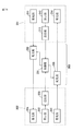
- FIG. 14 shows a third configuration example of the cooperative processing system applied to the town of FIG.
- the collaborative processing system includes a plurality of communication devices 201 and 202 and a control device 203.
- the communication device 201 is installed in the guest room HA1 of the hotel HA, and the communication device 202 is one of the other guest rooms other than the guest room HA1, for example, in the guest room HB1 (FIG. 4) of the hotel HB. Yes.
- the same communication devices as the communication devices 201 and 202 are installed in the guest rooms of the hotel HA other than the guest room HA1, the guest rooms of the hotel HB other than the guest room HB1, the guest rooms of the hotel HC, and the guest rooms of the hotel HD. The explanation is omitted.
- control device 203 can be installed in a control center independent of the hotel HA or HD, or can be installed in the hotel HA or HB, for example, integrated with the communication device 201 or 202.
- control device 203 can be shared by the communication devices 201 and 202 and the other communication devices constituting the collaborative processing system.
- the communication device 201 includes a light collecting unit 211, an instruction unit 212, a transmission unit 213, and a light receiving unit 214.
- the condensing unit 211 corresponds to the sensor unit 31 of FIG.
- the condensing unit 211 condenses sunlight (senses light) and causes the light distribution unit 232 to enter (supply) it.
- the instruction unit 212 corresponds to the instruction unit 32 of FIG.
- the instruction unit 212 instructs, for example, light that is a sensor output of the light collecting unit 221 included in the other communication device 202 in accordance with a user operation or the like. That is, the instruction unit 212 generates instruction information corresponding to an instruction such as light of the light collecting unit 221 included in another communication device 202 according to a user operation or the like, and supplies the instruction information to the transmission unit 213.
- the transmission unit 213 corresponds to the transmission unit 33 in FIG.
- the transmission unit 213 transmits instruction information from the instruction unit 212 to the control unit 231.
- the light receiving unit 214 corresponds to the receiving unit 34 in FIG.
- the light receiving unit 214 provides sensor output instructed according to the instruction information transmitted to the control unit 231, that is, for example, light output from the light collecting unit 221 included in another communication device 202. Light is received from the light unit 233.
- the communication device 202 is configured similarly to the communication device 201.
- the communication device 202 includes a light collecting unit 221, an instruction unit 222, a transmission unit 223, and a light receiving unit 224 that are similar to the light collecting unit 211, the instruction unit 212, the transmission unit 213, and the light receiving unit 214, respectively.
- the light collecting unit 221, an instruction unit 222, a transmission unit 223, and a light receiving unit 224 that are similar to the light collecting unit 211, the instruction unit 212, the transmission unit 213, and the light receiving unit 214, respectively.
- the light that is the sensor output of the light collecting unit 221 is supplied to the light distribution unit 233.
- the light receiving unit 224 is a sensor output that is instructed according to the instruction information transmitted to the control unit 231, for example, the light collected by the light collecting unit 211 of the communication device 201 from the light distribution unit 232. receive.
- the control device 203 includes a control unit 231 and light distribution units 232 and 233.
- the control unit 231 corresponds to the control unit 51 in FIG.
- the control unit 231 follows the instruction information transmitted from the transmission unit 213 of the communication apparatus 201 or the instruction information transmitted from the transmission unit 223 of the communication apparatus 202, that is, the sensor output by the light distribution units 232 and 233, that is, the collecting point.
- the provision of light collected by the light unit 211 and light collected by the light collecting unit 221 is controlled.
- the light distribution unit 232 corresponds to the sending unit 52 in FIG.
- the light distribution unit 232 configures another communication device (for example, the communication device 202 or a collaborative processing system) for the communication device 201 using the light collected by the light collecting unit 221 of the communication device 201 under the control of the control unit 231. To other communication devices).
- another communication device for example, the communication device 202 or a collaborative processing system
- the light distribution unit 233 corresponds to the transmission unit 53 in FIG.
- the light distribution unit 233 configures another communication device (for example, the communication device 201 or a collaborative processing system) for the communication device 202 using the light collected by the light collecting unit 221 of the communication device 202 according to the control of the control unit 231. To other communication devices).
- another communication device for example, the communication device 201 or a collaborative processing system
- the light collected by the condensing unit 211 of the communication device 201 installed in the guest room HA1 of the hotel HA is incident on the light distribution unit 232, and at the hotel HB.
- the light condensed by the condensing unit 221 of the communication device 202 installed in the guest room HB1 enters the light distribution unit 233.
- the instruction unit 212 collects the communication device 202 according to the operation of the user. Instruction information for instructing the light collected by the light unit 221 is generated and supplied to the transmission unit 213.
- the transmission unit 213 transmits instruction information from the instruction unit 212 to the control unit 231.
- the control unit 231 receives the instruction information transmitted from the transmission unit 213 of the communication apparatus 201, and controls the provision of light to the communication apparatus 201 according to the instruction information.
- control unit 231 controls the light distribution unit 233 on which the light collected by the light collecting unit 221 of the communication device 202 is incident, and the light collected by the light collecting unit 221 is transmitted to the communication device. 201 to provide.
- the light receiving unit 214 receives light provided from the light distribution unit 233.
- the light received by the light receiving unit 214 of the communication device 201 is used to adjust the display of images and the brightness of illumination in the guest room HA1.
- the hotel HA and HB for example, when the hotel HB has a better sunlight, the light collected at the hotel HB is divided and given to the hotel HA. Any of the HBs can provide a similar environment for light.
- the light distribution unit 232 that provides the light collected by the light collecting unit 211 of the communication device 201 to another communication device can be provided in the communication device 201 instead of the control device 203.
- the light distribution unit 233 that provides the light collected by the light collecting unit 221 of the communication device 202 to another communication device can be provided in the communication device 202 instead of the control device 203.
- condensing unit 211 In addition to providing one condensing unit 211 in the guest room HA1, it is possible to provide one in a plurality of guest rooms in the hotel HA or one in the hotel HA.
- the condensing part 221 is also the same.
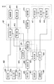
- FIG. 15 shows a fourth configuration example of the collaborative processing system applied to the town of FIG.
- the collaborative processing system includes a plurality of communication devices 301 and 302 and a control device 303.
- the communication device 301 is installed in the guest room HA1 (FIG. 4) of the hotel HA, and the communication device 302 is one of the other guest rooms other than the guest room HA1, for example, installed in the guest room HB1 of the hotel HB. Yes.
- the same communication devices as the communication devices 301 and 302 are installed in the guest rooms of the hotel HA other than the guest room HA1, the guest rooms of the hotel HB other than the guest room HB1, the guest rooms of the hotel HC, and the guest rooms of the hotel HD. The explanation is omitted.
- control device 303 can be installed in a control center independent of the hotel HA or HD, or can be installed in the hotel HA or HB, for example, integrated with the communication device 301 or 302.
- control device 303 can be shared by the communication devices 301 and 302 and other communication devices constituting the collaborative processing system.
- the communication device 301 includes a light collecting unit 311, an instruction unit 312, a transmission unit 313, a light receiving unit 314, a display unit 315, a power storage unit 316, a light amount detection unit 317, and a light distribution unit 332.
- the condensing unit 311 corresponds to the sensor unit 31 in FIG.
- the condensing unit 311 condenses sunlight (senses light) and causes the light distribution unit 332 to be incident (supplied).
- the instruction unit 312 corresponds to the instruction unit 32 in FIG.
- the instruction unit 312 gives a predetermined instruction in accordance with, for example, a user operation, a light amount detected by the light amount detection unit 317, or the like. That is, the instruction unit 312 generates instruction information for performing a predetermined instruction in accordance with a user operation, a light amount detected by the light amount detection unit 317, and the like, and supplies the instruction information to the transmission unit 313.
- the transmission unit 313 corresponds to the transmission unit 33 in FIG.
- the transmission unit 313 transmits instruction information from the instruction unit 312 to the control unit 331.
- the light receiving unit 314 corresponds to the receiving unit 34 in FIG.
- the light receiving unit 314 provides the sensor output instructed according to the instruction information transmitted to the control unit 331, that is, for example, the light output from the light collecting unit 321 included in the other communication device 302.
- Light is received from the light unit 333 and supplied to the display unit 315.
- the light receiving unit 314 receives light provided from the light distribution unit 332 and supplies the light to the display unit 315.
- the display unit 315 displays an image using the light from the light receiving unit 314 and illuminates the room HA1.
- the power storage unit 316 uses electricity supplied from the light distribution unit 332 to generate electricity (electric power) obtained by performing photovoltaic power generation (a technique for converting light energy into electrical energy using the photoelectric effect of a silicon semiconductor). Is stored.
- the electric power stored in the power storage unit 316 is used in electrical products that perform image display, indoor lighting of the guest room HA1, and the like, as necessary.
- the light amount detection unit 317 detects the amount of light collected by the light collecting unit 311 and supplies it to the instruction unit 312.
- the light distribution unit 332 corresponds to the sending unit 52 in FIG.
- the light distribution unit 332 configures another communication device (for example, the communication device 302 or a collaborative processing system) with respect to the light collected by the light collecting unit 311 of the communication device 301 according to the control of the control unit 331.
- Other communication devices for example, the communication device 302 or a collaborative processing system
- the light receiving unit 314, or the power storage unit 316 is provided (distributed).
- the communication device 302 is configured similarly to the communication device 301.
- the communication device 302 is also provided with blocks corresponding to the display unit 315, the power storage unit 316, and the light amount detection unit 317.
- one or more communication devices such as the communication device 302 that are not all of the plurality of transmission devices that constitute the collaborative processing system are blocks corresponding to the display unit 315, the power storage unit 316, and the light amount detection unit 317. It is possible to configure without providing.
- the control device 303 includes a control unit 331.
- the control unit 331 corresponds to the control unit 51 in FIG.
- the control unit 331 follows the instruction information transmitted from the transmission unit 313 of the communication device 301, the instruction information transmitted from the transmission unit 323 of the communication device 302, etc., that is, the sensor output by the light distribution units 332 and 333, that is, The provision of light condensed by the light condensing unit 311 and light condensed by the light condensing unit 321 is controlled.
- the light distribution unit 332 that provides the light collected by the light collecting unit 311 of the communication device 301 to another communication device can be provided in the control device 303 instead of the communication device 301.
- the light distribution unit 333 that provides the light collected by the light collecting unit 311 of the communication device 302 to another communication device can be provided in the control device 303 instead of the communication device 302.
- condensing unit 311 In addition to providing one condensing unit 311 in the guest room HA1, it is possible to provide one in a plurality of guest rooms in the hotel HA or one in the hotel HA.
- the condensing part 321 is also the same.
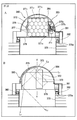
- FIG. 16 is a cross-sectional view illustrating a configuration example of the guest room HA1 in which the communication device 301 of FIG. 15 is installed.
- the condensing part 311 is installed in a favorable position per sun, such as the roof of the hotel HA or the rooftop.
- the condensing unit 311 condenses sunlight and supplies the light obtained by the condensing to the light distribution unit 332.
- the light quantity detection part 317 is attached to the position which can detect the light quantity of the light condensed by the condensing part 311.
- the light distribution unit 332 includes flat reflectors 342L and 342R, and distributes (distributes) the light collected by the light collecting unit 311 to another communication device, the daylighting unit 345, or the solar panel 341. To do.
- an optical fiber 343 connected to another communication device is provided on the left side of the light distribution unit 332, and a daylighting unit 345 is provided on the lower side of the light distribution unit 332.
- a solar panel 341 is provided on the right side of the light distribution unit 332.
- the light distribution unit 332 When distributing the light collected by the light collecting unit 311 to another communication device, the light distribution unit 332 reflects the light collected by the light collecting unit 311 to the left side. The light collected by the light unit 311 is emitted (provided) to the light receiving unit of another communication device such as the light receiving unit 324 (FIG. 15) of the communication device 302 via the optical fiber 343.
- the light distribution unit 332 distributes the light collected by the light collection unit 311 to the light collection unit 345, the light distribution unit 332 allows the light collected by the light collection unit 311 to pass downward.
- the light condensed by the condensing unit 311 is emitted to the daylighting unit 345.
- the light distribution unit 332 distributes the light collected by the light collection unit 311 to the solar panel 341
- the light distribution unit 332 reflects the light collected by the light collection unit 311 to the right side.
- the light collected by the light collecting unit 311 is emitted to the solar panel 341.
- the solar panel 341 performs photovoltaic power generation using the light from the light distribution unit 332 and supplies the electricity (electric power) obtained as a result to the power storage unit 316.
- the power storage unit 316 stores the power supplied from the solar panel 341 as described above.
- the daylighting unit 345 is configured by stacking a flat light output panel 346 and a similarly flat display unit 315 so as to form a gap therebetween. That is, the daylighting unit 345 has a structure in which a gap is sandwiched between the light output panel 346 and the display unit 315.
- the daylighting part 345 is provided under the light distribution part 332, and constitutes the wall surface of the guest room HA1 from which an actual mountain view can be seen.
- the daylighting unit 345 is installed such that the display unit 315 faces the indoor side of the guest room HA1 and the light output panel 346 faces the outdoor side (outside) of the guest room HA1.
- the daylighting unit 345 performs daylighting and uses the light obtained by the daylighting to display an image, illuminate the room HA1, etc.
- light distributed from the light distribution unit 332 enters the gap of the daylighting unit 345. Furthermore, light distributed from other communication devices, such as light collected by the light collecting unit 321 (FIG. 15) of the communication device 302 and distributed from the light distribution unit 333, in the gap of the daylighting unit 345. Enters through the optical fiber 344.
- the light incident on the gap of the daylighting unit 345 is, for example, parallel light.
- the light output panel 346 emits scattered light as light for displaying an image on the display unit 315 to the display unit 315.
- the light output panel 346 scatters light (parallel light) incident on the gap of the daylighting unit 345 and emits the resulting scattered light to the display unit 315.
- the light output panel 346 also emits light, scatters the light, and emits the light to the display unit 315.
- the display unit 315 is composed of, for example, the liquid crystal display device described with reference to FIGS. 6 and 7, and displays an image using light (scattered light) emitted from the light output panel 346 as a backlight.
- the display unit 315 also functions as a lighting device by adjusting the amount of light that the light output from the light output panel 346 enters into the cabin HA1 as described with reference to FIG.
- an operation mode in which the display unit 315 displays an image is referred to as an image mode
- an operation mode in which the display unit 315 functions as an illumination device is also referred to as an illumination mode.
- the guest room HA1 can be provided with a lighting unit 345 in which the display unit 315 operates in the image mode and a lighting unit 345 in which the display unit 315 operates in the illumination mode.
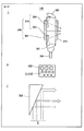
- FIG. 17 shows a configuration example of a sunlight lighting device used as the light collecting unit 311.
- a sunlight daylighting device 380 is disposed on the roof (rooftop) of a building and condenses sunlight indicated by an arrow A by passing through a lens holder 372 in which a large number of lenses are disposed.
- the condensed sunlight is reflected by the reflecting plate 373 and guided in the direction indicated by the arrow B to be guided into the building.
- FIG. 18 is a diagram showing a more detailed configuration example of the sunlight lighting device 380 of FIG.
- a in FIG. 18 is a front view of the sunlight collecting device 380 viewed from the front
- B in FIG. are the side views which looked at the sunlight lighting apparatus 380 from the side surface.
- Reflector 373 is provided on the rear of the lens holder 372, and reflects light lens 371 n is focused, leading to the building (light distributing unit 332).
- the lens holder 372 is rotatably held by a lens holder support member 377 so as to be rotatable around a horizontal axis 376.
- the lens holder 372 is driven by the motor 374 via the gears 375 1 and 375 2 and rotates (rotates) about the horizontal shaft 376.
- the lens holder 372 when the morning or evening or the like, a low sun, in the state shown by the solid line in B of FIG. 18, a solar L1 is focused by the lens 371 n, the reflection plate 373 When the sun is high, such as in the daytime, the light is reflected as shown by a chain line, and sunlight L2 is collected by the lens 371 n and reflected by the reflector 373 to enter the building. Lead.
- the lens holder support member 377 is integrally attached to the rotation base 378, and the roller 382 of the rotation base 378 is rotatably mounted on the rail 379a of the cylindrical fixed base 379, and the motor. 381 is rotated about the vertical axis YY.
- the sensor 383 detects the direction of the sun. Based on the direction of the sun detected by the sensor 383, the motors 374 and 381 are controlled so that the surface of the lens 371 n (surface perpendicular to the optical axis) of the lens holder 372 faces the direction of the sun. Be controlled.
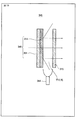
- FIG. 19 is a cross-sectional view showing a configuration example of the daylighting unit 345 of FIG.
- the daylighting unit 345 includes a display unit 315 disposed on the indoor side of the guest room HA1 and a light output panel 346 disposed on the outdoor side (outside).
- the light output panel 346 is configured by superposing a flat backlight portion 351 and a flat light receiving portion 314 in the same manner.
- the backlight part 351 is arrange
- the light receiving unit 314 is configured by the liquid crystal display device described with reference to FIGS. 6 and 7, for example, similarly to the display unit 315.
- the backlight unit 351 emits light serving as a backlight using the power stored in the power storage unit 316 as a power source.
- the display unit 315 displays an image using the light obtained by the daylighting of the daylighting unit 345 or the light emitted from the backlight unit 351 as a backlight, and also functions as an illumination device.
- the liquid crystal cell 152 (FIG. 6) of the liquid crystal display device as the light receiving unit 314 is in a light-shielding state.
- the fourth state (D in FIG. 7) is entered.
- the light receiving unit 314 blocks light incident from the backlight unit 351 side, receives light incident from the light distribution unit 332, and light incident from another communication device via the optical fiber 344, Reflected to the display unit 315 side.
- the liquid crystal cell 151 (FIG. 6) is in a light scattering state, and the liquid crystal cell 152 is in a light transmission state or a light shielding state in units of pixels according to an image signal. This is the second state (B in FIG. 7).
- the display unit 315 is a light scattering liquid crystal cell 151 that receives light reflected by the light receiving unit 314, light incident from the light distribution unit 332, and light incident from another communication device via the optical fiber 344.
- the liquid crystal cell 152 controls the scattering (transmission) of the scattered light obtained by the scattering and displays an image.
- the liquid crystal cell 151 (FIG. 6) in the liquid crystal display device as the light receiving unit 314 is in a light scattering state.
- the liquid crystal cell 152 will be in the 3rd state (C of FIG. 7) which will be in a light transmissive state.
- the light receiving unit 314 scatters light incident from the backlight unit 351 side and emits it to the display unit 315.
- the liquid crystal display device as the display unit 315 is in the second state (B in FIG. 7), for example, in the same manner as described above, and displays an image using the light from the light receiving unit 314 as a backlight.
- FIG. 20 is a diagram illustrating another configuration example of the daylighting unit 345 in FIG.
- a in FIG. 20 is a cross-sectional view showing another configuration example of the daylighting unit 345 in FIG.
- the light receiving unit 314 constituting the light output panel 346 is constituted by two triangular prisms 363 and 364 instead of the liquid crystal display device of FIG.
- a lens 361 is provided on the optical fiber 344 side of the daylighting unit 345, and a lens 362 is provided on the light distribution unit 332 (FIG. 16) side.
- the lens 361 collects light (parallel light) incident on the daylighting unit 345 from another communication device via the optical fiber 344 on the prism 363.
- the lens 362 collects light incident on the light collecting unit 345 from the light distribution unit 332 on the prism 364.
- the prismatic prism 363 is arranged so that one of its side surfaces is in contact with the backlight unit 351, receives light from the lens 361, and reflects it to the display unit 315 side.
- the triangular prism 364 is also disposed so that one of its side surfaces is in contact with the backlight unit 351, receives light from the lens 362, and reflects it to the display unit 315 side.
- the prism 363 is disposed at a position near the optical fiber 344 of the backlight unit 351 with the other one of the side surfaces directed toward the upper and lower middle points of the backlight unit 351.
- the prism 364 is arranged at a position near the light distribution part 332 (FIG. 16) of the backlight part 351 with the other one of the side faces directed to the upper and lower middle points of the backlight part 351.
- 20B shows a configuration example of the prism 363 viewed from the display unit 315 side.
- a circular reflector is provided on the surface of the prism 363 where the light from the lens 361 is collected, and the light from the lens 361 is received and reflected by the reflector.
- the area of the reflector on the upper and lower midpoints of the backlight unit 351 is larger, so that the reflector on the upper and lower midpoint of the backlight 351 has a larger area. A quantity of light is reflected.
- C in FIG. 20 schematically shows the amount of light reflected by the prism 363.
- the prism 363 reflects a larger amount of light as the position is closer to the upper and lower middle points of the backlight unit 351.
- the prism 364 is configured in the same manner as the prism 363.
- the display unit 315 displays an image using the light obtained by the daylighting of the daylighting unit 345 or the light emitted from the backlight unit 351 as a backlight, and Functions as a lighting device.
- the prism 363 serving as the light receiving unit 314 enters from another communication device via the optical fiber 344.
- the light collected by the lens 361 is received and reflected to the display unit 315 side.
- a prism 364 as the light receiving unit 314 receives light incident from the light distribution unit 332 and collected by the lens 362 and reflects it to the display unit 315 side.
- the liquid crystal cell 151 (FIG. 6) is in a light scattering state, and the liquid crystal cell 152 is in a light transmission state or a light shielding state in units of pixels according to an image signal. This is the second state (B in FIG. 7).
- the display unit 315 is a light scattering liquid crystal cell 151 that scatters the light reflected by the prisms 363 and 364 as the light receiving unit 314 and transmits (blocks) the scattered light obtained by the scattering to the liquid crystal cell. By controlling at 152, an image is displayed.
- the display unit 315 displays an image using the light emitted from the backlight unit 351 as the backlight, the light emitted from the backlight unit 351 enters the display unit 315.
- the liquid crystal display device as the display unit 315 is in the second state (B in FIG. 7), for example, in the same manner as described above, and displays an image using the light from the backlight unit 351 as the backlight. To do.
- the light distribution unit 332 is composed of flat reflectors 342 ⁇ / b> L and 342 ⁇ / b> R, and the light collected by the light collecting unit 311 Light is distributed (distributed) (provided) (guided) to the panel 341.
- the light distribution unit 332 supplies the light collected by the light collecting unit 311 to the daylighting unit 345 as an operation mode, a display mode, and an operation mode provided to another communication device as a light distribution.
- the mode and the operation mode provided to the solar panel 341 are referred to as a power storage mode, respectively.
- 21A shows a state of the light distribution unit 332 in the display mode.
- the flat reflectors 342L and 342R constituting the light distribution unit 332 are arranged, for example, at the same interval as the gap of the daylighting unit 345 (FIG. 16).
- the reflection plate 342L is disposed on the upper side of the light output panel 346 along the extension line of the light output panel 346 (FIG. 16) on the outdoor side of the light distribution unit 332, and the reflection plate 342R is provided with the light distribution.
- the unit 332 is arranged on the upper side of the display unit 315 along an extension line of the display unit 315 (FIG. 16) on the indoor side.
- the flat reflectors 342L and 342R are rotatable about the upper axis extending in the depth direction in the drawing as a rotation axis.
- the reflectors 342L and 342R constituting the light distribution unit 332 are rotated in a state parallel to the light output panel 346 (FIG. 16) and the display unit 315, respectively.
- the condensed light is provided (guided) to the daylighting unit 345 located on the lower side.
- the daylighting unit 345 uses the light provided from the light distribution unit 332 as described above to display an image on the display unit 315 as described with reference to FIGS. 19 and 20.
- 21B shows a state of the light distribution unit 332 in the light distribution mode.
- the right reflector 342R of the reflectors 342L and 342R constituting the light distributor 332 reflects the light collected by the condenser 311 to the left optical fiber 343 side. And the left reflector 342L is rotated so as not to prevent the light reflected by the reflector 342R from entering the optical fiber 343.
- the light condensed by the condensing unit 311 is reflected to the left by the reflecting plate 342R and enters the optical fiber 343.
- Other communication devices such as the communication device 302 (FIG. 15) enter the light distribution mode, and the light collected by the other communication devices is transmitted via the optical fiber 344 (FIG. 16).
- the daylighting unit 345 uses the light provided from the other communication device to display as described in FIG. 19 and FIG. An image is displayed on the unit 315.
- 21C shows a state of the light distribution unit 332 in the power storage mode.
- the left reflector 342L of the reflectors 342L and 342R constituting the light distribution part 332 reflects the light collected by the condenser 311 to the right solar panel 341 side. While being rotated, the right reflecting plate 342R is rotated so as not to prevent the light reflected by the reflecting plate 342L from entering the solar panel 341.
- the light collected by the light collecting unit 311 is reflected to the right side by the reflector 342L and enters the solar panel 341.
- the solar panel 341 generates power using the light provided from the light distribution unit 332 in this way.
- the power obtained by the power generation of the solar panel 341 is stored in the power storage unit 316, and the power stored in the power storage unit 316 is used for driving the backlight unit 351 (FIGS. 19 and 20) and other electrical products. Is done.
- FIG. 22A illustrates a case where the user performs an operation for specifying a device that uses light (hereinafter also referred to as an optical device) for use or an operation for adjusting the brightness of illumination. It is a flowchart explaining the process (collaboration control) of the control part 331 performed.
- a communication device that is provided with light from another communication device among a plurality of communication devices including the communication devices 301 and 302 that constitute the collaborative system is also referred to as a first device.
- a communication device that provides light to the camera is also referred to as a second device.
- the communication device 301 (FIG. 15) installed in the guest room HA1 It becomes a device.
- the default operation mode of the light distribution unit 332 is, for example, the display mode (A in FIG. 21).
- the default operation mode of the light distribution unit is the display mode.
- control unit 331 controls the operation modes of the light distribution unit 332 of the communication device 301 and the light distribution units of other communication devices constituting the collaborative processing system.
- the communication device 301 installed in the guest room HA1 becomes the first device, and the instruction unit 312 In response to the operation, instruction information is generated.
- the instruction unit 312 displays an instruction indicating the instruction of the optical device and a request for light. Generate information.
- the instruction unit 312 displays instruction information indicating the brightness instruction after the adjustment and the light request. Generate.
- the instruction information generated by the instruction unit 312 is transmitted from the transmission unit 313 to the control unit 331.
- step S201 the control unit 331 receives the instruction information indicating the light request from the transmission unit 313 of the communication device 301 that is the first device, and receives the information, and the process proceeds to step S202.
- step S202 based on the instruction information from the communication apparatus 301 as the first apparatus, the control unit 331 determines the optical device and brightness that are instructed according to the instruction information, that is, the optical device designated by the user of the guest room HA1. In addition, it is determined whether or not the light amount P1 necessary for the brightness of the adjusted illumination is insufficient with the light amount P2 of the light collected by the light condensing unit 311 of the communication device 301 as the first device.
- the light amount P2 of the light condensed by the light condensing unit 311 of the communication device 301 as the first device is detected by the light amount detecting unit 317 and included in the instruction information, so that the communication device as the first device. 301 is transmitted to the control unit 331 regularly or irregularly or in response to a request from the control unit 331.
- step S202 the optical device instructed in accordance with the instruction information from the communication device 301 as the first device and the light amount P1 necessary for the brightness are only the light amount P2 of the light collected by the light condensing unit 311. If it is determined that there is sufficient (when the expression P1 ⁇ P2 is satisfied), the process returns to step S201.
- the amount of light necessary for the brightness of the optical device specified by the user of the guest room HA1 and the adjusted illumination is only the light collected by the light collecting unit 311 of the communication device 301 installed in the guest room HA1. If it can be covered, the operation mode of the light distribution unit 332 of the communication device 301 that is the first device remains in the display mode, and the communication device 301 is caused by the communication device 301 that is the first device. The operation mode of the light distribution unit of another communication apparatus such as 302 is not changed.
- the light distribution unit 332 in the display mode provides the light collected by the light collecting unit 311 to the daylighting unit 345 as described with reference to FIG.
- the daylighting unit 345 provides the light distribution unit 332 as described with reference to FIG.
- the light condensed by the light condensing unit 311 is received, and an image is displayed on the display unit 315 in the image mode using the light as a backlight.
- the daylighting unit 345 provides the light collecting unit 332 provided as described in A of FIG.
- the light collected by the light unit 311 is received, and the amount of light incident on the interior of the cabin HA1 is adjusted in the display unit 315 in the illumination mode.
- step S202 the optical device instructed according to the instruction information from the communication device 301 as the first device and the amount of light necessary for brightness are insufficient for the amount of light collected by the condensing unit 311. If it is determined that the expression P1 ⁇ P2 does not hold, the process proceeds to step S203, and the control unit 331 other than the communication device 301 that is the first device, other communication devices configuring the collaborative processing system. Among these, it is determined whether or not there is a communication device that collects light having a light amount equal to or greater than a predetermined light amount threshold value and is in a power storage mode.
- control unit 331 controls the operation modes of the light distribution unit 332 of the communication device 301 and the light distribution units of other communication devices that form the collaborative processing system.
- Reference numeral 331 recognizes the operation mode of the light distribution unit of all the communication devices that constitute the collaborative processing system.
- the light amount detection unit 317 detects the light amount of the light collected by the light collecting unit 311, and the instruction unit 312 includes the light amount in the instruction information and transmits it.
- the data is transmitted to the control unit 331 via the unit 313 periodically or irregularly or in response to a request from the control unit 331.
- the instruction information including the amount of light collected by the other communication device is transmitted to the control unit 331. It has become.
- control unit 331 Based on the amount of light included in the instruction information transmitted from each communication device that constitutes the collaborative processing system, the control unit 331 is configured so that the amount of light collected by each communication device is greater than or equal to a predetermined light amount threshold. Recognize whether there is.
- control part 331 is the light quantity with which the recognition result of the operation mode of the light distribution part of each communication apparatus which comprises a cooperation processing system, and the light quantity of the light condensed by each communication apparatus are more than a predetermined light quantity threshold value. Based on the recognition result of whether or not there is, in step S203, other than the communication device 301 as the first device, other communication devices constituting the collaborative processing system collect light having a light amount equal to or greater than a predetermined light amount threshold. It is determined whether or not there is a communication device that is illuminated and is in the power storage mode.
- the predetermined light intensity threshold value used in the determination in step S203 is specified by, for example, the optical device or brightness that is instructed according to the instruction information from the communication device 301 as the first device, that is, the user of the cabin HA1. It is assumed that the value is equal to or greater than the light amount P1 required for the brightness of the optical device and the adjusted illumination.
- step S203 light other than the first communication device 301, which is a communication device that constitutes the collaborative processing system, collects light having a light amount equal to or greater than a predetermined light amount threshold value, and enters the power storage mode.
- the control unit 331 controls the light distribution unit 332 of the communication device 301 serving as the first device, and sets the operation mode of the light distribution unit 332 to the power storage mode.
- the light distribution unit 332 in the power storage mode provides the light collected by the light collecting unit 311 to the solar panel 341 as described in FIG. 21C, and the solar panel 341 Is used to store electric power in the power storage unit 316.
- backlight unit 351 (FIGS. 19 and 20) is driven by the power stored in power storage unit 316.
- the light emitted from the backlight unit 351 driven by the power stored in the power storage unit 316 is backed up.
- An image is displayed on the image mode display unit 315 as a light.
- the light emitted from the backlight unit 351 driven by the power stored in the power storage unit 316 is generated in the room HA1. Is adjusted in the display unit 315 in the illumination mode.
- step S203 light other than the first communication device 301 that collects light having a light amount equal to or greater than a predetermined light amount threshold is collected in other communication devices that form the collaborative processing system.
- a communication device that is, a communication device that can be a second device capable of providing a sufficient amount of light to another communication device (hereinafter, as appropriate, In the case where there is a possible communication device)
- the process proceeds to step S205, and the control unit 331 selects a communication device as the second device from the possible communication devices.
- control unit 331 can use the instruction information including the optical device instruction or the illumination brightness instruction transmitted from the communication apparatus 301 as the first apparatus.
- a communication device as the second device is selected from the communication devices.
- the second device (the light condensed by the light condensing unit) is instructed indirectly.
- step S205 after selecting the second device, the control unit 331 controls the second device to enter the light distribution mode.
- the control unit 331 controls the light distribution unit 333 of the communication device 302 that is the second device, and thereby the light distribution unit 333. Is set to the light distribution mode, and the light collected by the light collecting unit 321 is provided (light distribution) to the communication device 301 as the first device.
- the operation mode of the light distribution unit 333 is the light distribution mode
- the light collected by the light collection unit 321 is light as described in FIG. Light is distributed to the daylighting unit 345 (FIG. 16) of the communication device 301 as the first device via the fiber 344 (FIG. 16).
- the daylighting unit 345 distributes light from the light distribution unit 333 of the communication device 302 that is the second device.
- the light collected by the light collecting unit 321 of the communication device 302 is received by the light receiving unit 314 (FIGS. 16, 19, and 20), and the light is used as a backlight to the image mode display unit 315. An image is displayed.
- the daylighting unit 345 distributes light from the light distribution unit 333 of the communication device 302 that is the second device.
- the light condensed by the condensing unit 321 of the communication device 302 is received by the light receiving unit 314 (FIGS. 16, 19, and 20), and the light enters the room HA1 in the illumination mode display unit 315.
- the amount of light to be adjusted is adjusted.
- the control unit 331 collects the optical device instructed according to the instruction information or the light amount necessary for brightness by the condensing unit 311 of the communication device 301 as the first device. It is determined whether the amount of light that is being used is insufficient.
- the control unit 331 is a second device, for example, by controlling the light distribution unit 333 of the communication device 302 so that the operation mode is set to the light distribution mode, and the light is collected by the light collection unit 321 of the communication device 302.
- the communication device 301 that is the first device provides the received light.
- the light collection provided according to the control of the control unit 331 that controls the provision of the light condensed by the light collection unit 321 of the second device (other communication device).
- Light collected by the light unit 321 is received and used as light for illuminating the liquid crystal cells 151 and 152 constituting the display unit 315, thereby displaying images and brightness (illumination) in the room HA1. Adjustments are made.
- step S205 the control unit 331 sets the operation mode of the light distribution unit 332 of the communication device 301, which is the first device, to the power storage mode, and then from the instruction unit 312 via the transmission unit 313 to the light collection unit 311.
- the instruction information including the light amount P2 of the light collected in step S202 is transmitted, the light amount P1 required for the brightness of the optical device designated by the user of the guest room HA1 and the adjusted illumination, as in step S202.
- the control unit 331 controls the light distribution unit 332 of the communication device 301 which is the first device, and sets the operation mode to the display mode.
- the light distribution unit 332 in the display mode provides the light collected by the light collecting unit 311 to the daylighting unit 345 as described with reference to FIG.
- the daylighting unit 345 provides the light distribution unit 332 as described with reference to FIG.
- the light condensed by the light condensing unit 311 is received by the light receiving unit 314 (FIGS. 15, 19, and 20), and an image is displayed on the display unit 315 in the image mode using the light as a backlight. .
- the daylighting unit 345 provides the light collecting unit 332 provided as described in A of FIG.
- the light condensed by the light unit 311 is received by the light receiving unit 314 (FIGS. 15, 19, and 20), and the amount of light that enters the room of the cabin HA1 is adjusted in the display unit 315 in the illumination mode.
- control unit 331 sets the operation mode of the light distribution unit 332 of the communication device 301 serving as the first device according to the instruction information from the instruction unit 312 of the communication device 301 serving as the first device. 21A), the light collected by the light collecting unit 311 of the communication device 301 is converted into the light distribution unit 332 of the communication device 301, and the light receiving unit 314 of the light collecting unit 345 of the communication device 301 (FIG. 15, 19 and 20).
- the light distribution unit 332 of the communication device 301 that is the first device enters the display mode according to the instruction information generated by the instruction unit 312 of the communication device 301 (A in FIG. 21).
- the light condensed by the condensing unit 311 is distributed to the light receiving unit 314 (FIGS. 15, 19, and 20) of the light collecting unit 345 of the communication device 301.
- step S204 the light distribution unit 332 of the communication device 301 that is the first device responds to the instruction information generated by the instruction unit 312 of the communication device 301 in accordance with the storage mode (see FIG. 21C), the light collected by the light collecting unit 311 of the communication device 301 is distributed to the solar panel 341 (FIG. 16) of the communication device 301.
- control unit 331 sets the operation mode of the light distribution unit 333 of the communication device 302 serving as the second device to the light distribution mode (see FIG. 5) according to the instruction information from the instruction unit 312 of the communication device 301 serving as the first device. 21B), the light collected by the light collecting unit 321 of the communication device 302 onto the light distribution unit 333 of the communication device 302 is converted into the light receiving unit of the light collecting unit 345 of the communication device 301 which is another communication device. The light is distributed to 314 (FIGS. 15, 19, and 20).
- the light distribution unit 333 of the communication device 302 that is the second device responds to the instruction information generated by the instruction unit 312 of the communication device 301 that is another communication device for the communication device 302 according to the light distribution mode (see FIG. 21B), the light collected by the condensing unit 321 of the communication device 302 serving as the second device is converted into the light receiving unit 314 of the daylighting unit 345 of the communication device 301 serving as the other communication device (FIGS. 15 and 19). , FIG. 20).
- FIG. 22 is control performed according to the light quantity condensed by the condensing part of each communication apparatus which comprises the cooperation processing system of FIG. 15 including the condensing part 311 of the communication apparatus 301.
- FIG. It is a flowchart explaining the process (collaboration control) of the part 331.
- step S211 the control unit 331 controls the light distribution unit 332 of the communication device 301 (FIGS. 15 and 16), which is the first device, to change the operation mode to the default display mode (A in FIG. 21). Then, the process proceeds to step S212.
- step S212 the control unit 331 determines whether or not the amount of light collected by the condensing unit 311 of the communication device 301 serving as the first device is less than a predetermined light amount threshold.
- the light amount P2 of the light collected by the light collecting unit 311 of the communication device 301 serving as the first device is detected by the light amount detecting unit 317, and is indicated by the instruction unit 312. It is included in the instruction information so as to be transmitted from the communication device 301 (the transmission unit 313) as the first device to the control unit 331 periodically or irregularly or in response to a request from the control unit 331. It has become.
- step S212 the first device is used by using the instruction information including the light amount P2 of the light collected by the light collecting unit 311 transmitted from the communication device 301 as the first device to the control unit 331. It is determined whether the amount of light collected by the condensing unit 311 of the communication device 301 is less than a predetermined light amount threshold.
- the predetermined light amount threshold value used in the determination in step S212 and step S213 to be described later is, for example, the light amount of light that is predicted to be used in the cabin HA1, that is, for example, display in the image mode or the illumination mode.
- the amount of light that illuminates the unit 315 is a minimum amount of light.
- step S212 If it is determined in step S212 that the amount of light collected by the condensing unit 311 of the communication device 301 serving as the first device is not less than a predetermined light amount threshold, that is, for example, image mode or illumination. If a sufficient amount of light is collected by the light collecting unit 311 as the amount of light that illuminates the mode display unit 315, the process returns to step S211.
- a predetermined light amount threshold that is, for example, image mode or illumination.
- the light distribution of the communication device 301 serving as the first device is performed.
- the operation mode of the unit 332 remains the display mode.
- the operation mode of the light distribution unit of another communication device such as the communication device 302 is not changed.
- the light distribution unit 332 in the display mode provides the light collected by the light collecting unit 311 to the daylighting unit 345 as described with reference to FIG.
- the daylighting unit 345 the light collected from the light collecting unit 311 provided from the light distribution unit 332 is received by the light receiving unit 314 (FIGS. 15, 19, and 20), and the light is backlit. As described above, an image is displayed on the display unit 315 in the image mode, or the amount of light incident on the interior of the guest room HA1 is adjusted in the display unit 315 in the illumination mode.
- step S212 if it is determined in step S212 that the amount of light collected by the condensing unit 311 of the communication device 301 as the first device is not less than a predetermined light amount threshold, that is, for example, the image mode or If a sufficient amount of light cannot be collected by the condensing unit 311 as the amount of light that illuminates the display unit 315 in the illumination mode, the process proceeds to step S213.
- a predetermined light amount threshold that is, for example, the image mode or If a sufficient amount of light cannot be collected by the condensing unit 311 as the amount of light that illuminates the display unit 315 in the illumination mode.
- the instruction information that is generated by the instruction unit 312 and transmitted from the transmission unit 313 to the control unit 331 includes the light amount P2 of the light collected by the light collection unit 311. Is used to determine that the amount of light condensed by the light condensing unit 311 is less than a predetermined light amount threshold.
- the instruction unit 312 indicates that the light amount detected by the light amount detection unit 317 is less than the predetermined light amount threshold value or is not less than the predetermined light amount threshold value, and further, the transmission unit It can be said that 313 transmits instruction information corresponding to an instruction from the instruction unit 312.
- step S213 the control unit 331 collects light having a light amount equal to or greater than a predetermined light amount threshold value in other communication devices that constitute the collaborative processing system other than the communication device 301 that is the first device. And it is determined similarly to the case of step S203 of A of FIG. 22 whether the communication apparatus which is in electrical storage mode exists.
- step S213 light other than the first communication device 301 that collects light having a light amount equal to or greater than a predetermined light amount threshold among other communication devices that constitute the collaborative processing system, and enters the power storage mode. If it is determined that no communication device is present, that is, a communication device that can be a second device capable of providing a sufficient amount of light among other communication devices. When the device does not exist, the process proceeds to step S214, and the control unit 331 controls the light distribution unit 332 of the communication device 301 that is the first device, and sets the operation mode of the light distribution unit 332 to the power storage mode. .
- the light distribution unit 332 in the power storage mode provides the light collected by the light collecting unit 311 to the solar panel 341 as described in FIG. 21C, and the solar panel 341 Is used to store electric power in the power storage unit 316.
- backlight unit 351 (FIGS. 19 and 20) is driven by the power stored in power storage unit 316.
- step S213 light other than the first communication device 301 that collects light having a light amount equal to or greater than a predetermined light amount threshold value is collected in other communication devices that constitute the collaborative processing system, and When it is determined that there is a communication device in the mode, that is, the communication device can be a second device capable of providing a sufficient amount of light among other communication devices. If there is a communication device, the process proceeds to step S215, and the control unit 331 selects a communication device as the second device from the possible communication devices, as in step S205 of FIG. .
- step S215 the control unit 331 controls the second device to enter the light distribution mode.
- the control unit 331 controls the light distribution unit 333 of the communication device 302 that is the second device, and thereby the light distribution unit 333. Is set to the light distribution mode, and the light collected by the light collecting unit 321 is provided (light distribution) to the communication device 301 as the first device.
- the operation mode of the light distribution unit 333 is the light distribution mode
- the light collected by the light collecting unit 321 is light as described in FIG. Light is distributed to the daylighting unit 345 (FIG. 16) of the communication device 301 as the first device via the fiber 344 (FIG. 16).
- the daylighting unit 345 the light collected from the light collecting unit 321 of the communication device 302 and distributed from the light distribution unit 333 of the communication device 302 as the second device is received by the light receiving unit 314 (FIG. 16, FIG. 16). 19 and 20), the image is displayed on the display unit 315 in the image mode using the light as a backlight, or the amount of light incident on the interior of the guest room HA1 is the display unit 315 in the illumination mode. Adjusted in
- the instruction unit 312 instructs that the light amount detected by the light amount detection unit 317 is less than a predetermined light amount threshold value, and the transmission unit 313 displays the instruction unit.
- Instruction information corresponding to the instruction 312 is transmitted to the control unit 331.
- the control unit 331 determines whether the light amount collected by the light collecting unit 311 of the communication device 301 is a sufficient light amount.
- the control unit 331 controls the light distribution unit 333 of the communication device 302, which is the second device, for example.
- the operation mode is set as the light distribution mode, and the light collected by the light collecting unit 321 of the communication device 302 is provided to the communication device 301 which is the first device.
- the light collection provided according to the control of the control unit 331 that controls the provision of the light condensed by the light collection unit 321 of the second device (other communication device).
- Light collected by the light unit 321 is received and used as light for illuminating the liquid crystal cells 151 and 152 constituting the display unit 315, thereby displaying images and brightness (illumination) in the room HA1. Adjustments are made.
- step S215 the process similar to the process after step S205 of A of FIG. 22 is performed.
- the light amount detection unit 317 detects the light amount of the light collected by the light collection unit 311, and the instruction unit 312 determines the light amount as the instruction information.
- the information is transmitted to the control unit 331 via the transmission unit 313, while the control unit 331 determines whether the light amount included in the instruction information from the communication device 301 is equal to or greater than a predetermined light amount threshold value.
- the instruction unit 312 determines whether the light amount detected by the light amount detection unit 317 is equal to or greater than a predetermined light amount threshold, and includes the determination result in the instruction information. It is possible to transmit to the control unit 331. The same applies to other communication devices that constitute the collaborative processing system.
- the operation mode of the light distribution unit 333 of the communication device 302 that is the second device is set to the light distribution mode, and the light collected by the light collecting unit 321 of the communication device 302 is the communication device that is the first device.
- the communication device 301 serving as the first device has the light distributed from the communication device 302 serving as the second device and the communication device 301 serving as the first device.
- Light collected by the light collecting unit 311 and distributed (provided) to the daylighting unit 345 via the light distribution unit 332 can also be used as light for illuminating the display unit 315.
- FIG. 23 shows a fifth configuration example of the cooperative processing system applied to the town of FIG.
- the collaborative processing system includes a plurality of communication devices 401 and 402 and a control device 403.
- the communication device 401 is installed in the guest room HA1 (FIG. 4) of the hotel HA, and the communication device 402 is one of other guest rooms other than the guest room HA1, for example, installed in the guest room HB1 of the hotel HB. Yes.
- a communication device similar to the communication devices 401 and 402 is also installed in the guest room of the hotel HA other than the guest room HA1, the guest room of the hotel HB other than the guest room HB1, each guest room of the hotel HC, and each guest room of the hotel HD. The explanation is omitted.
- control device 403 can be installed in a control center independent of the hotel HA or HD, or can be installed in the hotel HA or HB, for example, integrated with the communication device 401 or 402.
- control device 403 can be shared by the communication devices 401 and 402 and other communication devices that constitute the collaborative processing system.
- the communication device 401 includes a light collecting unit 411, an imaging unit 412, a light distribution unit 413, a transmission unit 414, an instruction unit 415, a transmission unit 416, a light receiving unit 417, a reception unit 418, and a display unit 419.
- the condensing unit 411 and the imaging unit 412 correspond to the sensor unit 31 in FIG.
- the condensing unit 411 collects sunlight (senses light) and causes the light distribution unit 413 to be incident (supplied).
- the imaging unit 412 captures an image (senses light) and outputs an image signal.
- the image signal output from the imaging unit 412 is supplied to the sending unit 414.
- the light distribution unit 413 and the sending unit 414 correspond to the sending unit 52 in FIG.
- the light distribution unit 413 configures another communication device (for example, the communication device 402 or a collaborative processing system) for the communication device 401 using the light collected by the light collecting unit 411 of the communication device 401 under the control of the control unit 431. To distribute light to other communication devices).
- another communication device for example, the communication device 402 or a collaborative processing system
- the sending unit 414 provides (transmits) an image signal as a sensor output of the imaging unit 412 of the communication device 401 to other communication devices under the control of the control unit 431.
- the instruction unit 415 corresponds to the instruction unit 32 in FIG.
- the instruction unit 415 gives a predetermined instruction in response to a user operation. That is, the instruction unit 415 generates instruction information for performing an image signal output by an imaging unit of another communication device, such as the imaging unit 422 of the communication device 402, or other predetermined instructions, according to a user operation or the like. Then, the data is supplied to the transmission unit 416.
- the transmission unit 416 corresponds to the transmission unit 33 in FIG.
- the transmission unit 416 transmits instruction information from the instruction unit 415 to the control unit 431.
- the light receiving unit 417 and the receiving unit 418 correspond to the receiving unit 34 in FIG.
- the light receiving unit 417 provides sensor output instructed according to the instruction information transmitted to the control unit 431, that is, for example, light output from the light collecting unit 421 included in the other communication device 402. Light is received from the light portion 423 and supplied to the display portion 419.
- the receiving unit 418 receives and displays an image signal output from the imaging unit of another communication device, that is, an image signal output from the imaging unit 422 of the communication device 402 and transmitted via the sending unit 424, for example. Part 419.
- the display unit 419 uses the light from the light receiving unit 417 to display an image corresponding to the image signal from the receiving unit 418 and illuminates the room HA1.
- the display unit 419 can display an image corresponding to an image signal output by a tuner or a player (not shown).
- the communication device 402 is configured in the same manner as the communication device 401.
- the communication device 402 is the same as the light collecting unit 411, the imaging unit 412, the light distribution unit 413, the transmission unit 414, the instruction unit 415, the transmission unit 416, the light receiving unit 417, the reception unit 418, and the display unit 419.
- a light collecting unit 421, an imaging unit 422, a light distribution unit 423, a transmission unit 424, an instruction unit 425, a transmission unit 426, a light receiving unit 427, a reception unit 428, and a display unit 429 are configured.
- the light collected by the light collecting unit 411 of the communication device 401 among the light provided by the light distribution units of other communication devices is the light distribution unit 413. Provided (light distribution).
- the image signal output by the imaging unit 412 of the communication device 401 among the image signals output by the imaging units of other communication devices is provided from the transmission unit 414 to the reception unit 428 of the communication device 402 ( Send).
- the control device 403 includes a control unit 431 and a storage unit 432.
- the control unit 431 corresponds to the control unit 51 in FIG.
- the control unit 431 follows the instruction information transmitted from the transmission unit 416 of the communication device 401, the instruction information transmitted from the transmission unit 426 of the communication device 402, and the information stored in the storage unit 432.
- the light distribution unit 413, the transmission unit 414, the light distribution unit 423, the transmission unit 424, the light distribution unit of other communication devices, and the provision of light and image signals as sensor outputs by the transmission unit are controlled. .
- the storage unit 432 stores information necessary for the control unit 431 to perform processing.
- the light collecting unit 411 is configured in the same manner as the light collecting unit 311 described with reference to FIGS.
- the condensing part 421 is the same.
- the imaging unit 412 is installed at a position where it can capture an image of a landscape seen from the hotel HA (in the guest room HA1), similarly to the imaging unit 111 described with reference to FIGS.
- the imaging unit 422 is also installed at a position where a landscape image seen from the hotel HB can be taken.
- the light distribution unit 413 is configured similarly to the light distribution unit 332 described with reference to FIGS. 15, 16, and 21. The same applies to the light distribution unit 423.
- the light receiving unit 417 is configured in the same manner as the light receiving unit 314 described with reference to FIG. 15, FIG. 19, and FIG.
- the display unit 419 is configured in the same manner as the display unit 315 described with reference to FIGS. 15, 16, 19, and 20, and thus includes the liquid crystal display device described with reference to FIGS. ing.
- the communication device 401 is provided with a daylighting unit similar to the daylighting unit 345 described in FIG. 16, FIG. 19, and FIG.
- the display part 419 comprises the lighting part provided in the communication apparatus 401 similarly to the light-receiving part 314 and the display part 315 which comprise the lighting part 345 (FIG. 16, FIG. 19, FIG. 20).
- FIG. 24A is a flowchart for explaining one of the processes performed on the image by the control unit 431 in FIG.
- the imaging unit 412 captures an image and outputs an image signal obtained as a result to the transmission unit 414.
- the sending unit 414 receives the image signal from the imaging unit 412 and temporarily stores it in a built-in memory (not shown) as necessary. Further, the transmission unit 414 transmits the image signal (including the image signal stored in the built-in memory) from the imaging unit 412 to another communication device such as the communication device 402 according to the control of the control unit 431.
- Other communication devices including the communication device 402 configuring the collaborative processing system also capture an image and transmit an image signal obtained as a result according to the control of the control unit 431, similarly to the communication device 401.
- the communication device 402 if the sending unit 424 is transmitting an image signal of an image captured by the imaging unit 422 to the communication device 401 according to the control of the control unit 431, the communication device 401
- the reception unit 418 receives an image signal transmitted (provided) from the transmission unit 424 of the communication apparatus 402 and supplies the received image signal to the display unit 419.
- step S301 the control unit 431 determines whether there is an instruction (request) to change the image displayed on the display unit 419 of the communication device 401 (an imaging unit that is capturing the image).
- the user of the guest room HA1 changes the image displayed on the display unit 419 from the current image (for example, a landscape image seen from the hotel HB) to another image (for example, a landscape image seen from the hotel HC).
- the instruction unit 415 generates instruction information for instructing the changed image according to the operation of the user of the guest room HA1, and the instruction information includes the instruction information of the guest room HA1.
- the user ID of the user is supplied to the transmission unit 416.
- the transmission unit 416 transmits the instruction information from the instruction unit 415 to the control unit 431.
- step S301 it is determined whether or not the instruction information indicating the changed image is transmitted from the transmission unit 416 to the control unit 431.
- step S301 If it is determined in step S301 that the instruction information indicating the changed image has not been transmitted, that is, for example, the user of the guest room HA1 continues to display the image currently displayed on the display unit 419. If it is desired, the process skips step S302 and proceeds to step S303.
- step S301 If it is determined in step S301 that the instruction information for instructing the changed image has been transmitted from the transmission unit 416 to the control unit 431, the process proceeds to step S302.
- the image displayed on the display unit 419 is controlled (switched) from the image captured by the imaging unit 422, which is the current image, to the image indicated by the instruction information. Proceed to step S303.
- step S302 the control unit 431 stops the transmission of the image signal output from the imaging unit 422 to the communication device 401 by controlling the transmission unit 424 of the communication device 402.
- control unit 431 controls a transmission unit of a communication device (hereinafter also referred to as an instructed device) having an imaging unit that captures an image instructed by instruction information from the transmission unit 416 of the communication device 401.
- a transmission unit of a communication device hereinafter also referred to as an instructed device
- an imaging unit that captures an image instructed by instruction information from the transmission unit 416 of the communication device 401.
- the reception unit 418 receives the image signal output from the imaging unit of the instructed device and transmitted to the display unit 419.
- the display unit 419 displays an image corresponding to the image signal from the receiving unit 418, that is, an image after change designated by the instruction information.
- step S303 the control unit 431 determines whether a predetermined time has elapsed since the display of the image currently displayed on the display unit 419 of the communication device 401 is started.
- step S303 when it is determined that the predetermined time has not elapsed since the display of the image currently displayed on the display unit 419 is started, that is, the display of the image currently displayed on the display unit 419. Since the time has started, there is a possibility that the user of the guest room HA1 may change the image currently displayed on the display unit 419 to another image without being fond of it. If so, the process returns to step S301.
- Step S303 when it is determined that a predetermined time has elapsed since the display of the image currently displayed on the display unit 419 is started, that is, the user of the guest room HA1 displays on the display unit 419.
- the control unit 431 determines the user ID of the user of the guest room HA1 and the user. Is associated (linked) with the metadata of the image currently displayed on the display unit 419 and stored (accumulated) in the storage unit 432.
- control unit 432 displays the metadata of the image currently displayed on the display unit 419 and the user ID of the user of the guest room HA1 included in the instruction information transmitted from the transmission unit 416 that instructs the image.
- the information is registered in the table stored in the storage unit 432 in association with each other.
- the process of A in FIG. 24 is performed for all communication devices constituting the collaborative processing system in addition to the communication device 401.
- FIG. 24B shows an example of a table stored in the storage unit 432.
- the storage unit 432 stores two tables, a pointer table and a user table.
- the pointer table includes a camera ID and an imaging unit for identifying the imaging unit of each communication device that constitutes the collaborative processing system, including the imaging unit 412 of the communication device 401 and the imaging unit 422 of the communication device 402. Are registered in association with metadata of an image captured by the camera and a pointer for accessing an image signal output by the imaging unit (capturing the image).
- the metadata of the image registered in the pointer table for example, information of an object (for example, a building, a river, a bridge, the sea, a mountain, or the sun) reflected in the image can be employed. .
- the administrator of the collaborative processing system recognizes what kind of object appears in the image captured by the imaging unit 412. Yes. Therefore, the metadata of the pointer table is registered in the pointer table, for example, by the administrator of the collaborative processing system.
- the date and time when the image was captured, the season, and the like can be used as the metadata of the image registered in the pointer table.
- the pointer registered in the pointer table for example, information for accessing a memory (not shown) of the sending unit 414 that temporarily stores an image signal output by the imaging unit 412 can be employed.
- the image signal output by the imaging unit 412 can be supplied from the sending unit 414 to the control unit 431 and temporarily stored in a memory built in the control unit 431.
- the image signal is registered in the pointer table.
- the pointer information for accessing a storage area for storing an image signal output from the imaging unit 412 in a memory built in the control unit 431 can be employed.
- the pointer for example, information for accessing the imaging unit can be employed.
- the user ID and the metadata of the image displayed on the display unit 419 are registered in association with each other according to the user operation of the user ID.
- the user ID of the user in the guest room HA1 corresponds to the metadata of the image displayed on the display unit 419 according to the user's operation in step S304 of FIG. Attached and registered.
- the metadata of the image registered in the user table that is, for example, the user ID of the user in the guest room HA1 and the metadata of the image displayed on the display unit 419 according to the user's operation are, for example, a pointer table In FIG. 4, the image is recognized from the metadata associated with the camera ID of the image capturing unit that captures the image.
- FIG. 24C is a flowchart for explaining another process performed by the control unit 431 in FIG.
- the process of C in FIG. 24 is performed using a pointer table and a user table stored in the storage unit 432.
- the instruction unit 415 generates instruction information for instructing the user ID of the user according to the operation of the employee of the hotel HA or the operation of the user staying in the guest room HA1, and the transmission unit 416 To supply.
- the transmission unit 416 transmits the instruction information from the instruction unit 415 to the control unit 431, and the control unit 431 receives the instruction information indicating the user ID transmitted from the transmission unit 416 as described above. To do.
- control unit 431 Upon receiving the instruction information indicating the user ID, the control unit 431 determines whether or not there is a user history of the user ID specified by the instruction information in step S311, that is, the user table stored in the storage unit 432. Whether the user ID indicated by the instruction information is registered.
- step S311 when it is determined that the user ID indicated by the instruction information is not registered in the user table stored in the storage unit 432, that is, for example, the user of the user ID indicated by the instruction information is If this is the first time accommodation in the town of FIG. 4, the process ends by skipping steps S312 and S313.
- step S311 If it is determined in step S311 that the user ID indicated by the instruction information is registered in the user table stored in the storage unit 432, the process proceeds to step S312 and the control unit 431 In the table, metadata associated with the user ID indicated by the instruction information is selected as attention metadata.
- one metadata is randomly selected from the plurality of metadata, for example. Are selected as attention metadata.
- control unit 431 After selecting the metadata of interest, the control unit 431 further selects an imaging unit that captures an image having the metadata of interest (the same metadata as the metadata of interest) in step S312 with the user ID indicated by the instruction information.
- the user that is, in this case, is selected as an imaging unit that captures an image to be shown to the user in the guest room HA1 (hereinafter, also referred to as “target imaging unit”), and the process proceeds to step S313.
- control unit 431 selects a pointer associated with the target metadata in the pointer table as the target pointer.
- one pointer is randomly selected as the target pointer from among the plurality of pointers.
- step S313 the control unit 431 controls the transmission unit of the communication apparatus having the target imaging unit so as to provide the communication device 401 with the image signal output by the target imaging unit selected in step S312.
- control unit 431 accesses a sending unit (hereinafter, also referred to as a noticed sending unit) containing a memory indicated by the noticed pointer, and provides an image signal output by the imaging unit (the noticed imaging unit) provided by the noticed sending unit. Is transmitted to the communication device 401.
- the attention sending unit is controlled.
- the reception unit 418 receives the image signal output from the attention imaging unit and transmitted from the attention transmission unit as described above, and supplies the image signal to the display unit 419 to display the corresponding image. .
- the process of C in FIG. 24 is performed for all communication devices that constitute the collaborative processing system in addition to the communication device 401.
- the instruction unit 415 determines whether another communication device is in accordance with the operation of the user in the guest room HA1.
- the reception unit 418 receives the image signal output by the imaging unit of another communication apparatus, which is instructed according to the instruction information corresponding to the instruction of the instruction unit 415, and displays the image signal.
- the unit 419 displays an image corresponding to the image signal received by the receiving unit 418.
- control unit 431 the user ID of the user of the guest room HA1 and the metadata of the image displayed on the display unit 419 are registered in the user table in association with each other.
- the control unit 431 is transmitted as a specific user ID, for example, from the communication device 401 to the control unit 431 using the pointer table and the user table.
- the imaging unit (attention imaging unit) that captures an image having metadata (attention metadata) associated with the user ID of the user of the guest room HA1 indicated by the coming instruction information is selected, and the attention imaging unit outputs Controls the provision of image signals.
- control unit 431 controls the transmission unit (attention transmission unit) of the communication device having the attention imaging unit, and causes the communication device 401 to transmit the image signal output by the attention imaging unit.
- the receiving unit 418 receives the image signal from the attention sending unit and causes the display unit 419 to display a corresponding image.
- the user has previously stayed in one of the guest rooms of the hotel HA or HD, and performed an operation to instruct display of an image in which a predetermined object such as the sea is reflected, and the image is displayed. If you continue to display it in your favorite, when you stay in one of the hotels HA or HD again, you do not have to perform an operation to instruct the display of the image showing your favorite object. An image showing the object is displayed.
- the hotel side where the user has stayed before remembers the user and gives the user a sense of hospitality according to the user's preference. Can do.
- FIG. 25A is a flowchart for explaining one of the processes performed by the control unit 431 in FIG.
- the light collecting unit 411 collects sunlight and emits light obtained by the light collection to the light distribution unit 413.
- the light distribution unit 413 distributes (provides) the light from the light collecting unit 411 to other communication devices such as the communication device 402 in accordance with the control of the control unit 431.
- Other communication devices that constitute the collaborative processing system including the communication device 402, collect sunlight as well as the communication device 401, and distribute the resulting light according to the control of the control unit 431.
- the light distribution unit 423 distributes the light collected by the light collecting unit 421 to the communication device 401 according to the control of the control unit 431.
- the light receiving unit 417 receives light distributed from the light distribution unit 423 of the communication device 402 and supplies the light to the display unit 419.
- the light from the light receiving unit 417 is emitted as illumination of the cabin HA1.
- step S331 the control unit 431 determines whether or not there is an instruction (request) for changing the brightness of the illumination by the display unit 419 of the communication device 401.
- the instruction unit 415 In response to the operation of the user of HA1, instruction information for instructing the brightness after the change is generated, and the instruction information including the user ID of the user of the guest room HA1 is supplied to the transmission unit 416.
- the transmission unit 416 transmits the instruction information from the instruction unit 415 to the control unit 431.
- step S331 it is determined whether or not the instruction information indicating the changed brightness is transmitted from the transmission unit 416 to the control unit 431.
- step S331 If it is determined in step S331 that the instruction information for instructing the changed brightness has not been transmitted, that is, for example, the user of the guest room HA1 determines the brightness of the illumination by the display unit 419 as the current brightness. If it is desired to continue, the process skips step S332 and proceeds to step S333.
- step S331 If it is determined in step S331 that the instruction information indicating the changed brightness has been transmitted from the transmission unit 416 to the control unit 431, the process proceeds to step S332, and the control unit 431 Control is performed to switch (change) the brightness of illumination by the display unit 419 of 401 from the current brightness to the brightness indicated by the instruction information, and the process proceeds to step S333.
- step S332 the control unit 431 controls the display unit 419 of the communication device 401 by controlling the light distribution unit of one or more other necessary communication devices among the other communication devices excluding the communication device 401.
- the one or more other light distribution units of the communication device 401 (the transmission unit 416) transmit the brightness of the illumination.
- the light collected by the condensing unit of the communication device is distributed to the communication device 401.
- the instruction information for instructing the changed brightness transmitted from the communication device 401 to the control unit 431 is the condensing unit of one or more other communication devices for obtaining the changed brightness. It can be said that the light collected at is indirectly indicated.
- the light receiving unit 417 is distributed from the light distribution unit of one or more other communication devices as described above, and the light collection unit of one or more other communication devices indicated by the instruction information.
- the display unit 419 illuminates the interior of the guest room HA1 with the light. That is, the display unit 419 illuminates the room HA1 with the brightness indicated by the instruction information.
- step S333 the control unit 431 determines whether or not a predetermined time has elapsed since the lighting with the current brightness by the display unit 419 of the communication device 401 is started.
- step S333 when it is determined that a predetermined time has not elapsed since the display unit 419 started lighting at the current brightness, that is, the display unit 419 starts lighting at the current brightness. If the time has not elapsed so much and the user of guest room HA1 may change the brightness of the lighting without having to like the brightness of the current lighting, the process The process returns to step S331.
- Step S333 when it is determined that a predetermined time has elapsed since the start of lighting at the current brightness by the display unit 419, that is, the user of the guest room HA1 has the brightness of the current lighting. If the user likes and keeps the brightness for a long time, the process proceeds to step S334, and the control unit 431 changes the user ID of the user in the guest room HA1 according to the user's operation.
- the light amount information relating to the light amount necessary to obtain the brightness of the illuminated light is associated (linked) and stored (accumulated) in the storage unit 432.
- the control unit 431 based on the instruction information instructing the brightness after the change, the communication device 401.
- the light collected by the light collecting unit of the one or more other communication devices is distributed to the communication device 401, and the communication device 401 The light distributed in this way is received by the light receiving unit 417.
- the light receiving unit 417 is collected by the light collecting unit of one or more other communication devices that are indirectly instructed by instruction information generated in response to a user's operation to change the brightness of the illumination. Receives light.
- step S334 the control unit 431 associates the user ID of the user in the guest room HA1 with the light amount information related to the light amount of the light received by the light receiving unit 417 according to the user's operation (hereinafter referred to as the light amount). (Also referred to as an information table) is stored in the storage unit 432.
- the light amount information for example, information on the brightness after the change indicated by the instruction information, information (setting) of the light distribution unit controlled based on the instruction information, and the like can be adopted.
- processing of A in FIG. 25 is performed for all communication devices constituting the collaborative processing system in addition to the communication device 401.
- FIG. 25B is a flowchart for explaining another process performed by the control unit 431 in FIG. 23 regarding light.
- the instruction unit 415 generates instruction information for instructing the user ID of the user according to the operation of the employee of the hotel HA or the operation of the user staying in the guest room HA1, and the transmission unit 416 To supply.
- the transmission unit 416 transmits the instruction information from the instruction unit 415 to the control unit 431, and the control unit 431 receives the instruction information indicating the user ID transmitted from the transmission unit 416 as described above. To do.
- control unit 431 Upon receiving the instruction information indicating the user ID, the control unit 431 determines whether or not there is a user history of the user ID specified by the instruction information in step S341, that is, the light amount information stored in the storage unit 432 It is determined whether the user ID indicated by the instruction information is registered in the table.
- step S341 when it is determined that the user ID indicated by the instruction information is not registered in the light amount information table stored in the storage unit 432, that is, for example, the user with the user ID indicated by the instruction information is displayed. If this is the first time accommodation in the town of FIG. 4, the process ends by skipping steps S342 and S343.
- step S341 If it is determined in step S341 that the user ID indicated by the instruction information is registered in the light amount information table stored in the storage unit 432, the process proceeds to step S342, and the control unit 431 In the light amount information table, the light amount information associated with the user ID indicated by the instruction information is selected (detected) as the attention light amount information.
- one light amount information when there are a plurality of light amount information associated with the user ID indicated by the instruction information, one light amount information is, for example, from among the plurality of light amount information, Randomly selected as attention light quantity information.
- step S342 the process proceeds from step S342 to step S343, and the control unit 431 determines, among the other communication devices other than the communication device 401, according to the attention light amount information selected in step S342.
- the control unit 431 determines, among the other communication devices other than the communication device 401, according to the attention light amount information selected in step S342.
- the brightness of the illumination by the display unit 419 of the communication device 401 is instructed according to the operation performed in the past by the user of the guest room HA1.
- the communication device 401 distributes the light collected by the light condensing unit of the one or more other communication devices from the light distribution unit of the one or more other communication devices so that the brightness is high.
- the light receiving unit 417 collects light from the light collecting unit of another communication device indicated by the instruction information that is distributed from the light distribution unit of one or more other communication devices as described above.
- the display unit 419 illuminates the interior of the guest room HA1 with the received light. That is, the display unit 419 illuminates the interior of the guest room HA1 with the brightness instructed according to the operation performed in the past by the user of the guest room HA1.
- processing of B in FIG. 25 is performed for all communication devices constituting the collaborative processing system in addition to the communication device 401.
- the instruction unit 415 indirectly and others depending on the operation of the user of the guest room HA1.
- the light receiving unit 417 is instructed according to the instruction information corresponding to the instruction of the instructing unit 415, and is condensed by the condensing unit of another communication device.
- the display unit 419 illuminates the cabin HA1 with the light received by the light receiving unit 417.
- control unit 431 the user ID of the user of the guest room HA1 and the light amount information of the image displayed on the display unit 419 are registered in the light amount information table in association with each other.
- the control unit 431 uses the light amount information table to obtain, for example, instruction information transmitted from the communication device 401 to the control unit 431 as a specific user ID.
- the light amount information (attention light amount information) associated with the user ID of the user in the guest room HA1 is selected, and the light distribution unit of one or more other communication devices necessary according to the attention light amount information is selected. Control the offer.
- control unit 431 controls the light distribution unit of one or more other communication devices that are necessary, and distributes the light collected by the light collection unit of the one or more other communication devices to the communication device 401.
- the light receiving unit 417 receives light from the light distribution unit of one or more necessary other communication devices, and the display unit 419 illuminates the interior of the guest room HA1 with the light.
- the brightness of the lighting is adjusted to the user's favorite brightness without performing an operation for adjusting the brightness of the lighting.
- the hotel side where the user has stayed before remembers the user and gives the user a sense of hospitality according to the user's preference. Can do.
- the display unit 419 is applicable to a light source for displaying an image, that is, a backlight.
- the process of FIG. 25 can also be applied to the adjustment of the brightness of an image displayed on the display unit 419.
- FIG. 26A is a flowchart for explaining one of processes performed by the control unit 431 in FIG. 23 regarding images and light.
- the light collecting unit 411 collects sunlight and emits light obtained by the light collection to the light distribution unit 413.
- the light distribution unit 413 distributes (provides) the light from the light collecting unit 411 to other communication devices such as the communication device 402 in accordance with the control of the control unit 431.
- Other communication devices that constitute the collaborative processing system including the communication device 402, collect sunlight as well as the communication device 401, and distribute the resulting light according to the control of the control unit 431.
- the light distribution unit 423 distributes the light collected by the light collecting unit 421 to the communication device 401 according to the control of the control unit 431.
- the light receiving unit 417 receives light distributed from the light distribution unit 423 of the communication device 402 and supplies the light to the display unit 419.
- the user of the guest room HA1 has, for example, an image of a television broadcast program, an image capturing unit of each communication device including the image capturing unit 412 of the communication device 401, and an image capturing unit 422 of the communication device 402.
- the display unit 419 displays an image in accordance with an instruction from the user of the guest room HA1 using the light from the light receiving unit 417 as a backlight. Is displayed.
- step S361 the control unit 431 determines whether there is an instruction (request) to change the brightness of image display by the display unit 419 of the communication apparatus 401, that is, the amount of light of the backlight.
- the communication device 401 has the instruction unit 415
- instruction information for instructing the light amount of the backlight corresponding to the changed brightness is generated, and the user ID of the user in the guest room HA1 and the display unit 419 are included in the instruction information.
- the image including the metadata of the displayed image is supplied to the transmission unit 416.
- the transmission unit 416 transmits the instruction information from the instruction unit 415 to the control unit 431.
- the metadata of the image displayed on the display unit 419 that is included in the instruction information for example, information on the genre (for example, sports program or news program) of the television broadcast program as the image, Information on the object displayed in the image can be employed.
- the user ID of the user in the guest room HA1 is input to the instruction unit according to, for example, an operation of an employee of the hotel HA or a user who stays in the guest room HA1, and the metadata of the image is, for example, the image Are included in the image signal.
- step S361 it is determined whether or not the instruction information for instructing the light amount of the backlight is transmitted from the transmission unit 416 to the control unit 431.
- step S361 when it is determined that the instruction information for instructing the amount of light of the backlight has not been transmitted, that is, for example, the user of the guest room HA1 sets the display brightness of the image on the display unit 419 to the current brightness. If it is desired to continue, the process skips step S362 and proceeds to step S363.
- step S361 when it is determined that the instruction information for instructing the light amount of the backlight has been transmitted from the transmission unit 416 to the control unit 431, the process proceeds to step S362, and the control unit 431 includes the communication device 401. Control is performed to switch (change) the light amount of the backlight for displaying an image on the display unit 419 from the current light amount to the light amount indicated by the instruction information, and the process proceeds to step S363.
- step S362 the control unit 431 controls the display unit 419 of the communication device 401 by controlling the light distribution unit of one or more other necessary communication devices among the other communication devices excluding the communication device 401. From the light distribution unit of one or more other communication devices, the amount of light of the backlight for displaying an image becomes the amount of light indicated by the instruction information from the communication device 401 (the transmission unit 416). The light collected by the light collecting unit of one or more other communication devices is distributed to the communication device 401.
- the instruction information for instructing the light amount of the backlight transmitted from the communication device 401 to the control unit 431 is condensed by the condensing unit of another communication device to obtain the light amount of the backlight. It can be said that the light is indirectly indicated.
- the display unit 419 displays an image using the light as a backlight. That is, the display unit 419 displays an image with the brightness corresponding to the light amount instructed by the instruction information.
- step S363 the control unit 431 determines whether or not a predetermined time has elapsed after the display of the current light amount by the display unit 419 of the communication device 401 is started.
- step S363 when it is determined that a predetermined time has not elapsed since the display unit 419 started displaying the image with the current light amount, that is, the display unit 419 displayed the image with the current light amount. If the time has not elapsed since the start of the operation, the user in guest room HA1 may change the amount of backlight without having to like the brightness of the current image display. The process returns to step S361.
- Step S363 when it is determined that a predetermined time has elapsed since the display of the image with the current light amount by the display unit 419 is started, that is, the user of the guest room HA1 If the brightness of the display is liked and the amount of light from the backlight remains for a certain length of time, the process proceeds to step S364, and the control unit 431 controls the user ID of the user in the guest room HA1 and the user's operation.
- the light amount information relating to the light amount of the backlight changed according to the above and the metadata of the image displayed on the display unit 419 are associated (linked) and stored (accumulated) in the storage unit 432.
- the control unit 431 uses a command other than the communication device 401 based on the instruction information for instructing the light amount of the backlight.
- the light collected by the light collecting unit of the one or more other communication devices is distributed to the communication device 401 from the light distribution unit of the one or more other communication devices.
- the light distributed in this manner is received by the light receiving unit 417.
- the light receiving unit 417 receives the light collected by the light collecting unit of one or more other communication devices that is indirectly instructed by the instruction information in accordance with the user's operation to change the light amount of the backlight. Receive light.
- step S364 the control unit 431 uses the user ID of the user in the guest room HA1, the light amount information regarding the light amount of the light received by the light receiving unit 417 according to the user's operation, and the light of the light amount.
- the control unit 431 uses the user ID of the user in the guest room HA1, the light amount information regarding the light amount of the light received by the light receiving unit 417 according to the user's operation, and the light of the light amount.
- the backlight the table associated with the image metadata displayed on the display unit 419 (as the backlight)
- the associated table (hereinafter also referred to as a backlight table) is stored in the storage unit 432.
- the metadata of an image registered in the backlight table in association with the user ID is also referred to as registered metadata.
- the light amount information for example, information on the light amount of the backlight indicated by the instruction information, information (setting) of the light distribution unit controlled based on the instruction information, and the like can be adopted.
- FIG. 26B is a flowchart for explaining another process performed by the control unit 431 in FIG. 23 regarding images and light.
- the process in B of FIG. 26 is performed using the backlight table stored in the storage unit 432 in the process of A in FIG.
- the user of the guest room HA1 has, for example, an image capturing unit of each communication device that constitutes the collaborative processing system including an image of a television broadcast program, an image capturing unit 412 of the communication device 401, and an image capturing unit 422 of the communication device 402.
- the display unit 419 displays an image in accordance with an instruction from the user of the guest room HA1 using the light from the light receiving unit 417 as a backlight. Is displayed.
- the instruction unit 415 receives the user ID of the user and the metadata of the image displayed on the display unit 419 in response to an operation of an instruction to display the image content by the user of the guest room HA1. Instruction information to be instructed is generated and supplied to the transmission unit 416.
- the transmission unit 416 transmits the instruction information from the instruction unit 415 to the control unit 431, and the control unit 431 instructs the user ID and image metadata transmitted from the transmission unit 416 as described above.
- the instruction information to be received is received.
- control unit 431 Upon receiving the instruction information indicating the user ID and the image metadata, the control unit 431 determines whether or not there is a user history of the user ID specified by the instruction information in step S371, that is, in the storage unit 432. It is determined whether or not the user ID indicated by the instruction information is registered in the stored backlight table.
- step S371 when it is determined that the user ID indicated by the instruction information is not registered in the backlight table stored in the storage unit 432, that is, for example, the user of the user ID indicated by the instruction information If this is the first time accommodation in the town of FIG. 4, the process ends by skipping steps S372 and S373.
- step S371 If it is determined in step S371 that the user ID indicated by the instruction information is registered in the backlight table stored in the storage unit 432, the process proceeds to step S372, and the control unit 431 In the backlight table, one or more sets of light amount information and registered metadata associated with the user ID indicated by the instruction information are selected (detected) as the attention set, and the process proceeds to step S373.
- control unit 431 selects an attention set including registered metadata that matches the metadata of the image indicated by the instruction information from one or more attention sets, and sets the light amount information of the attention set. Select (detect) as attention light quantity information.
- the light receiving unit 417 collects light from the light collecting unit of another communication device indicated by the instruction information that is distributed from the light distribution unit of one or more other communication devices as described above.
- the display unit 419 receives the received light and displays an image using the light as a backlight. That is, the display unit 419 displays an image having metadata that matches the metadata of the image with the amount of light instructed according to the operation performed when the user of the guest room HA1 has viewed the image in the past. .
- the instruction unit 415 may indirectly perform other operations according to the operation of the user in the guest room HA1.
- the light receiving unit 417 is instructed according to the instruction information corresponding to the instruction of the instructing unit 415, and is condensed by the condensing unit of another communication device.
- the display unit 419 displays an image using the light received by the light receiving unit 417 as a backlight.
- the control unit 431 the user ID of the user of the guest room HA1, the metadata of the image displayed on the display unit 419 (registered metadata), and the backlight when the image is displayed are displayed in the backlight table.
- the light quantity information relating to the light quantity is registered in association with each other.
- the control unit 431 uses the backlight table to obtain instruction information transmitted from the communication apparatus 401 to the control unit 431 as a specific user ID, for example.
- One or more sets of registered metadata and light quantity information associated with the user ID of the user of the instructing guest room HA1 are selected, and the instruction information points out of the one or more sets of light quantity information.
- the attention light amount information is detected from the metadata, that is, the light amount information associated with the registered metadata that matches the metadata of the image displayed on the display unit 419.
- control unit 431 controls the provision of light by the light distribution unit of one or more other necessary communication devices according to the attention light quantity information.
- control unit 431 controls the light distribution unit of one or more other communication devices that are necessary, and distributes the light collected by the light collection unit of the one or more other communication devices to the communication device 401.
- the light receiving unit 417 receives light from the light distribution unit of one or more other necessary communication devices, and the display unit 419 uses the light as a backlight to display an image on the display unit 419. indicate.
- the backlight light amount is adjusted to the user's preferred light amount without performing an operation to adjust the backlight light amount.
- the adjustment of the light amount of the backlight is performed for each image (metadata) displayed on the display unit 419.
- the hotel side where the user has stayed before remembers the user and gives the user a sense of hospitality according to the user's preference. Can do.
- the light amount of the backlight is controlled.
- the light amount of the lighting device independent of the display unit 419 in the guest room HA1 can be controlled instead of the light amount of the backlight. Is possible.
- a display unit 419 including a lighting unit (not shown) including the lighting unit 345 including the lighting unit 345 including the lighting unit 345) illustrated in FIG.
- a display unit 419 including a lighting unit (not shown) including the lighting unit 345 including the lighting unit 345 including the lighting unit 345) illustrated in FIG.
- it can be provided on the ceiling.
- FIG. 27 shows a configuration example of the guest room HA1 in which the communication device 401 is installed as described above.
- FIG. 27A is a perspective view schematically showing a configuration example of the guest room HA1 in which the communication device 401 is installed, with the display unit 419 provided on the ceiling.
- the display unit 419 (including a lighting unit (not shown)) of the communication device 401 is provided on the ceiling with the display surface for displaying an image facing the indoor side of the guest room HA1.
- the display unit 419 provided on the ceiling for example, it is possible to display an image of an empty landscape that would be seen if the ceiling of the guest room HA1 was not present.
- FIG. 28B an image of a sky view in a state where the sun can be seen
- FIG. 28C the imaging unit of the communication device installed on the top floor of the hotel HA turns the sun into a cloud.
- An image of a sky landscape that is hidden and invisible is captured, and the display unit 419 displays an image of the sky landscape in which the sun is visible or the sun is hidden behind a cloud according to a user operation. It is possible to display an image of the sky landscape in the absence.
- the user can enjoy a feeling as if the user is in a roof balcony, for example.
- a user staying in a guest room other than the top floor can enjoy a feeling as if staying in a guest room on the top floor.
- the user can enjoy a feeling as if he / she is staying in a guest room on the ground floor.
- FIG. 28 shows a configuration example of an embodiment of a computer in which a program for executing the series of processes described above is installed.
- the program can be recorded in advance in a hard disk 505 or ROM 503 as a recording medium built in the computer.
- the program is stored temporarily on a removable recording medium 511 such as a flexible disk, a CD-ROM (Compact Disc Read Only Memory), an MO (Magneto Optical) disc, a DVD (Digital Versatile Disc), a magnetic disc, or a semiconductor memory. It can be stored permanently (recorded).
- a removable recording medium 511 can be provided as so-called package software.
- the program is installed on the computer from the removable recording medium 511 as described above, or transferred from the download site to the computer wirelessly via a digital satellite broadcasting artificial satellite, or LAN (Local Area Network),
- the program is transferred to a computer via a network such as the Internet, and the computer can receive the program transferred in this manner by the communication unit 508 and install it in the built-in hard disk 505.
- the computer has a CPU (Central Processing Unit) 502 built-in.
- An input / output interface 510 is connected to the CPU 502 via the bus 501, and the CPU 502 operates the input unit 507 including a keyboard, a mouse, a microphone, and the like by the user via the input / output interface 510.
- ROM Read Only Memory
- the CPU 502 also receives a program stored in the hard disk 505, a program transferred from a satellite or a network, received by the communication unit 508, installed in the hard disk 505, or a removable recording medium 511 installed in the drive 509.
- the program read and installed in the hard disk 505 is loaded into a RAM (Random Access Memory) 504 and executed.
- the CPU 502 performs processing according to the above-described flowchart or processing performed by the configuration of the above-described block diagram.
- the CPU 502 outputs the processing result from the output unit 506 configured with an LCD (Liquid Crystal Display), a speaker, or the like via the input / output interface 510, or from the communication unit 508 as necessary. Transmission and further recording on the hard disk 505 are performed.
- processing steps for describing a program for causing a computer to perform various types of processing do not necessarily have to be processed in time series according to the order described in the flowchart, but in parallel or individually. This includes processing to be executed (for example, parallel processing or processing by an object).
- the program may be processed by a single computer, or may be processed in a distributed manner by a plurality of computers. Furthermore, the program may be transferred to a remote computer and executed.
- control unit 431 configuring the control device 403 performs the processing of FIG. 24 for all communication devices configuring the collaborative processing system, but the processing of FIG.
- Each communication apparatus constituting the processing system can perform the communication apparatus itself (self) in a distributed manner while sharing the pointer table and the user table (B in FIG. 24).
Landscapes
- Business, Economics & Management (AREA)
- Tourism & Hospitality (AREA)
- Engineering & Computer Science (AREA)
- Human Resources & Organizations (AREA)
- Strategic Management (AREA)
- General Business, Economics & Management (AREA)
- Entrepreneurship & Innovation (AREA)
- Marketing (AREA)
- Theoretical Computer Science (AREA)
- Physics & Mathematics (AREA)
- Economics (AREA)
- General Physics & Mathematics (AREA)
- Health & Medical Sciences (AREA)
- General Health & Medical Sciences (AREA)
- Data Mining & Analysis (AREA)
- Primary Health Care (AREA)
- Operations Research (AREA)
- Quality & Reliability (AREA)
- Telephonic Communication Services (AREA)
- Management, Administration, Business Operations System, And Electronic Commerce (AREA)
- Two-Way Televisions, Distribution Of Moving Picture Or The Like (AREA)
Priority Applications (3)
| Application Number | Priority Date | Filing Date | Title |
|---|---|---|---|
| EP09708769A EP2249306A4 (en) | 2008-02-04 | 2009-02-04 | COMMUNICATION DEVICE, COMMUNICATION PROCESS AND PROGRAM |
| US12/865,047 US20100328092A1 (en) | 2008-02-04 | 2009-02-04 | Communication device, communication method and program |
| CN2009801072396A CN101965587A (zh) | 2008-02-04 | 2009-02-04 | 通信装置、通信方法和程序 |
Applications Claiming Priority (2)
| Application Number | Priority Date | Filing Date | Title |
|---|---|---|---|
| JP2008024092A JP5207030B2 (ja) | 2008-02-04 | 2008-02-04 | 通信装置、通信方法、及び、プログラム |
| JP2008-024092 | 2008-02-04 |
Publications (1)
| Publication Number | Publication Date |
|---|---|
| WO2009099081A1 true WO2009099081A1 (ja) | 2009-08-13 |
Family
ID=40952155
Family Applications (1)
| Application Number | Title | Priority Date | Filing Date |
|---|---|---|---|
| PCT/JP2009/051837 Ceased WO2009099081A1 (ja) | 2008-02-04 | 2009-02-04 | 通信装置、通信方法、及び、プログラム |
Country Status (5)
| Country | Link |
|---|---|
| US (1) | US20100328092A1 (enExample) |
| EP (1) | EP2249306A4 (enExample) |
| JP (1) | JP5207030B2 (enExample) |
| CN (1) | CN101965587A (enExample) |
| WO (1) | WO2009099081A1 (enExample) |
Families Citing this family (6)
| Publication number | Priority date | Publication date | Assignee | Title |
|---|---|---|---|---|
| JP2012155114A (ja) * | 2011-01-26 | 2012-08-16 | Sony Corp | 表示システムおよびバックライトシステム |
| JP5652297B2 (ja) * | 2011-03-30 | 2015-01-14 | 富士通株式会社 | 情報端末、情報漏洩防止方法および情報漏洩防止プログラム |
| JP2014093204A (ja) * | 2012-11-05 | 2014-05-19 | Sony Corp | 音響照明装置およびプログラム |
| KR101799293B1 (ko) * | 2013-05-29 | 2017-11-20 | 삼성전자주식회사 | 디스플레이 장치, 디스플레이 장치 제어 방법 및 컴퓨터 판독 가능한 기록 매체 |
| CN104060933B (zh) * | 2014-03-13 | 2015-12-30 | 上海快联门业有限公司 | 一种基于红外线侦测启闭状态的门窗 |
| US9857040B1 (en) * | 2015-08-20 | 2018-01-02 | X Development Llc | Kinematically linked optical components for light redirection |
Citations (8)
| Publication number | Priority date | Publication date | Assignee | Title |
|---|---|---|---|---|
| JPH0643478A (ja) | 1992-07-24 | 1994-02-18 | Sharp Corp | 液晶表示装置 |
| JPH09270204A (ja) | 1996-04-01 | 1997-10-14 | Rafuooles Eng Kk | 太陽光採光装置 |
| JP2001305473A (ja) | 2000-04-21 | 2001-10-31 | Matsushita Electric Works Ltd | 太陽光採光装置 |
| JP2002320214A (ja) * | 2001-04-19 | 2002-10-31 | Webstream:Kk | 視聴管理方法、視聴管理システム |
| JP2004120390A (ja) * | 2002-09-26 | 2004-04-15 | Fuji Photo Film Co Ltd | ライブ映像取得支援サービスサーバ |
| JP2005130163A (ja) * | 2003-10-23 | 2005-05-19 | Hagoromo:Kk | ライブ映像配信システム |
| JP2007108677A (ja) | 2005-09-14 | 2007-04-26 | Sony Corp | プロジェクタ、視聴覚システムおよび画像表示方法 |
| JP2007156562A (ja) * | 2005-11-30 | 2007-06-21 | Toshiba Corp | 擬似旅行体験システム |
Family Cites Families (10)
| Publication number | Priority date | Publication date | Assignee | Title |
|---|---|---|---|---|
| JPH09205602A (ja) * | 1996-01-29 | 1997-08-05 | Sony Corp | 疑似窓 |
| US20040230486A1 (en) * | 2003-05-15 | 2004-11-18 | Greenlee Garrett M. | System and method for creating a dynamic and interactive simulated remote-locale atmosphere |
| WO2005043932A2 (en) * | 2003-10-20 | 2005-05-12 | Johnson Research And Development Co., Inc. | Portable multimedia projection system |
| US20050280706A1 (en) * | 2004-08-25 | 2005-12-22 | Chiou-muh Jong | Method and apparatus to simulate an outdoor window for panorama viewing from a room |
| KR101087853B1 (ko) * | 2004-10-05 | 2011-11-30 | 엘지전자 주식회사 | 디지털 텔레비젼 시스템 및 그 운용 방법 |
| US20080062323A1 (en) * | 2004-11-03 | 2008-03-13 | Koninklijke Philips Electronics, N.V. | High Intensity Display Screen Based Electronic Window |
| US7469155B2 (en) * | 2004-11-29 | 2008-12-23 | Cisco Technology, Inc. | Handheld communications device with automatic alert mode selection |
| JP2007013694A (ja) * | 2005-06-30 | 2007-01-18 | Sony Corp | 双方向コミュニケーション装置及び接続方法 |
| DE202005011574U1 (de) * | 2005-07-22 | 2006-11-23 | Aeg Gesellschaft für Moderne Informationssysteme mbH | Flüssigkristallanzeige |
| JP2008109446A (ja) * | 2006-10-26 | 2008-05-08 | Funai Electric Co Ltd | 液晶テレビジョンおよび液晶表示装置 |
-
2008
- 2008-02-04 JP JP2008024092A patent/JP5207030B2/ja not_active Expired - Fee Related
-
2009
- 2009-02-04 CN CN2009801072396A patent/CN101965587A/zh active Pending
- 2009-02-04 WO PCT/JP2009/051837 patent/WO2009099081A1/ja not_active Ceased
- 2009-02-04 US US12/865,047 patent/US20100328092A1/en not_active Abandoned
- 2009-02-04 EP EP09708769A patent/EP2249306A4/en not_active Withdrawn
Patent Citations (8)
| Publication number | Priority date | Publication date | Assignee | Title |
|---|---|---|---|---|
| JPH0643478A (ja) | 1992-07-24 | 1994-02-18 | Sharp Corp | 液晶表示装置 |
| JPH09270204A (ja) | 1996-04-01 | 1997-10-14 | Rafuooles Eng Kk | 太陽光採光装置 |
| JP2001305473A (ja) | 2000-04-21 | 2001-10-31 | Matsushita Electric Works Ltd | 太陽光採光装置 |
| JP2002320214A (ja) * | 2001-04-19 | 2002-10-31 | Webstream:Kk | 視聴管理方法、視聴管理システム |
| JP2004120390A (ja) * | 2002-09-26 | 2004-04-15 | Fuji Photo Film Co Ltd | ライブ映像取得支援サービスサーバ |
| JP2005130163A (ja) * | 2003-10-23 | 2005-05-19 | Hagoromo:Kk | ライブ映像配信システム |
| JP2007108677A (ja) | 2005-09-14 | 2007-04-26 | Sony Corp | プロジェクタ、視聴覚システムおよび画像表示方法 |
| JP2007156562A (ja) * | 2005-11-30 | 2007-06-21 | Toshiba Corp | 擬似旅行体験システム |
Non-Patent Citations (1)
| Title |
|---|
| See also references of EP2249306A4 * |
Also Published As
| Publication number | Publication date |
|---|---|
| EP2249306A1 (en) | 2010-11-10 |
| CN101965587A (zh) | 2011-02-02 |
| JP5207030B2 (ja) | 2013-06-12 |
| JP2009187111A (ja) | 2009-08-20 |
| EP2249306A4 (en) | 2012-10-17 |
| US20100328092A1 (en) | 2010-12-30 |
Similar Documents
| Publication | Publication Date | Title |
|---|---|---|
| JP5207030B2 (ja) | 通信装置、通信方法、及び、プログラム | |
| JP6118006B1 (ja) | 情報通信方法、情報通信装置およびプログラム | |
| US20090174658A1 (en) | System and method of adjusting viewing angle for display based on viewer positions and lighting conditions | |
| JP6378511B2 (ja) | 情報通信方法、情報通信装置およびプログラム | |
| CN102027807A (zh) | 用于对照明和/或播放图像加以控制的方法及交互系统 | |
| CN1894962A (zh) | 具有多个图像尺寸的投影图像的投影仪和方法 | |
| US20110254877A1 (en) | Display system and device with sustainable power generation | |
| JP2003195845A (ja) | 画像表示方法 | |
| JPWO2014103156A1 (ja) | 情報通信方法 | |
| US20040140973A1 (en) | System and method of a video capture monitor concurrently displaying and capturing video images | |
| JP4843901B2 (ja) | 表示装置 | |
| JP5608307B1 (ja) | 情報通信方法 | |
| US20070273845A1 (en) | System and method for multi-directional positioning of projected images | |
| CN108989774A (zh) | 一种影像互动展示系统及方法 | |
| KR20170129536A (ko) | Vr 관광 망원경 및 그 제어 방법 | |
| JPH11345691A (ja) | 照明環境調整方法、照明環境調整システムおよび照明器具 | |
| KR101136670B1 (ko) | 영상 중계 시스템 및 그 방법 | |
| US20180199011A1 (en) | Systems and methods for documenting exhibit experiences | |
| KR20200100221A (ko) | 스마트 미러 시스템 | |
| KR20220159924A (ko) | 복수의 사용자 단말들을 제어하는 군중 제어 시스템 | |
| WO2020045141A1 (ja) | 情報処理装置、情報処理方法、及びプログラム | |
| KR20200100222A (ko) | 스마트 미러 시스템의 구동 방법 |
Legal Events
| Date | Code | Title | Description |
|---|---|---|---|
| WWE | Wipo information: entry into national phase |
Ref document number: 200980107239.6 Country of ref document: CN |
|
| 121 | Ep: the epo has been informed by wipo that ep was designated in this application |
Ref document number: 09708769 Country of ref document: EP Kind code of ref document: A1 |
|
| WWE | Wipo information: entry into national phase |
Ref document number: 12865047 Country of ref document: US Ref document number: 2009708769 Country of ref document: EP |
|
| NENP | Non-entry into the national phase |
Ref country code: DE |