WO2009093588A1 - 画像処理装置、画像信号補正方法、補正マトリクス算出方法及び撮像装置 - Google Patents
画像処理装置、画像信号補正方法、補正マトリクス算出方法及び撮像装置 Download PDFInfo
- Publication number
- WO2009093588A1 WO2009093588A1 PCT/JP2009/050809 JP2009050809W WO2009093588A1 WO 2009093588 A1 WO2009093588 A1 WO 2009093588A1 JP 2009050809 W JP2009050809 W JP 2009050809W WO 2009093588 A1 WO2009093588 A1 WO 2009093588A1
- Authority
- WO
- WIPO (PCT)
- Prior art keywords
- image
- color
- pixel
- correction matrix
- group
- Prior art date
- Legal status (The legal status is an assumption and is not a legal conclusion. Google has not performed a legal analysis and makes no representation as to the accuracy of the status listed.)
- Ceased
Links
Images


Classifications
-
- H—ELECTRICITY
- H04—ELECTRIC COMMUNICATION TECHNIQUE
- H04N—PICTORIAL COMMUNICATION, e.g. TELEVISION
- H04N17/00—Diagnosis, testing or measuring for television systems or their details
- H04N17/002—Diagnosis, testing or measuring for television systems or their details for television cameras
-
- H—ELECTRICITY
- H04—ELECTRIC COMMUNICATION TECHNIQUE
- H04N—PICTORIAL COMMUNICATION, e.g. TELEVISION
- H04N23/00—Cameras or camera modules comprising electronic image sensors; Control thereof
- H04N23/80—Camera processing pipelines; Components thereof
- H04N23/84—Camera processing pipelines; Components thereof for processing colour signals
- H04N23/85—Camera processing pipelines; Components thereof for processing colour signals for matrixing
Definitions
- the present invention relates to an image signal correction method for correcting a color image signal, a calculation method of a correction matrix used when correcting a color image signal, and an image processing apparatus and an imaging apparatus employing the image signal correction method.
- Japanese Patent No. 3755921 shoots one subject assuming a standard photographing environment, There is disclosed a method of performing correction by multiplying an image signal by a correction coefficient so that the output signal becomes uniform. Japanese Patent No. 3755921
- An object of the present invention is to provide an image processing apparatus, an image signal correction method, a correction matrix calculation method, and an imaging apparatus.
- a plurality of groups determined according to the arrangement of the color filters are acquired from the storage unit
- the image processing apparatus includes a correction unit that corrects an image signal of a type to be corrected by using the acquired correction matrix and all types of image signals of the pixels.
- a plurality of groups determined according to the arrangement of the color filters Among these, it is determined which group it belongs to, and a correction matrix corresponding to the group to which each pixel belongs is acquired from a storage unit that stores the group and the correction matrix in association with each other, and the acquired correction matrix And an image signal correction method for correcting the type of image signal to be corrected using the image signal of all types in each pixel.
- a correction matrix calculation method used when correcting a color image generated based on an output signal from an image sensor having a color filter of a predetermined arrangement, wherein the image sensor is When a color image is acquired by photographing a plurality of color charts having different spectral characteristics, and each pixel of the color image is divided into a plurality of groups determined according to the arrangement of the color filters, a plurality of types are obtained.
- This correction matrix calculation method calculates the correction matrix so that at least one type of image signal value for each color chart substantially matches between at least two groups.
- an image sensor having color filters in a predetermined arrangement and each pixel of a color image generated based on an output signal from the image sensor are determined according to the arrangement of the color filters.
- a determination unit that determines which group of the plurality of groups belongs, a storage unit that stores the group and the correction matrix in association with each other, and a correction matrix that corresponds to the group to which each of the pixels belongs.
- An imaging apparatus comprising: a correction unit that corrects an image signal of a type to be corrected using the correction matrix acquired from the storage unit and all types of image signals in the pixels. is there.
- image signals are corrected for pixels belonging to a group using a correction matrix associated with the group.
- the spectral characteristics representing the characteristics of the signal to be corrected can be flexibly corrected. Since sufficient correction can be performed for all target subjects, it is possible to correct noise caused by color mixing with high accuracy for all subjects to be photographed.
- FIG. 1 is a diagram illustrating a schematic configuration of an imaging apparatus according to a first embodiment of the present invention. It is the flowchart which showed the procedure of the image signal correction method which concerns on the 1st Embodiment of this invention. It is the figure which showed an example of the primary color filter which concerns on the 2nd Embodiment of this invention. It is the figure which showed an example of the image signal allocated to each pixel of a picked-up image when the image signal produced
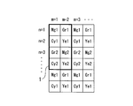
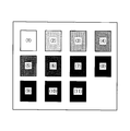
- FIG. 1 is a diagram illustrating an example of a complementary color filter that is two-dimensionally arranged in front of an image sensor such as a color CCD.
- the complementary color filter has a basic array 1 in which four color filters of magenta (Mg), green (Gr), cyan (Cy), and yellow (Ye) are regularly arranged. It is configured to be repeatedly arranged in the horizontal and vertical directions.
- Mg magenta
- Gr green
- Cy cyan
- Ye yellow
- the subscripts “1” and “2” are attached to each color filter depending on the arrangement of adjacent color filters. Filters with different subscripts have different spectral characteristics due to the influence of color mixing.
- Luminance signal Here, first, the influence of the complementary color filter shown in FIG. 1 on the luminance signal of each pixel of the captured image will be considered.
- the luminance signal of each pixel is created by the following equation (1) using the output signals of 2 ⁇ 2 color filters constituting the complementary color filter.
- Y (n, m) represents, for example, the luminance signal of the pixel (target pixel) in the nth row and mth column in the captured image
- CF (n, m) represents the color filter in the nth row and mth column. Represents the output signal.
- Y (n, m) [CF (n, m) + CF (n + 1, m)] + [CF (n, m + 1) + CF (n + 1, m + 1)] (1)
- the luminance signal of each pixel when the spectral characteristics of the filters of the same color are the same, the luminance signal of each pixel always has the same spectral characteristics regardless of the position on the captured image. Become. However, as shown by the subscript in FIG. 1, when the spectral characteristics of each color filter are affected by color mixing, the spectral characteristics of the luminance signal of each pixel change according to the position of the pixel on the captured image. It will be.
- the luminance signal Y (n, m) of the pixel (n, m) is expressed by the following equation (4).
- Y (n, m) [CF (n, m) + CF (n + 1, m)] + [CF (n, m + 1) + CF (n + 1, m + 1)] (4)
- the luminance signal Y of each pixel (1,1), (2,1), (3,1), (4,1) arranged in the first column in the captured image is as follows.
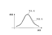
- FIG. 2 shows an example of spectral characteristics of the luminance signals Y (1,1) and Y (2,1) in the pixels (1,1) and (2,1).
- the spectral characteristic of the luminance signal changes depending on the position on the captured image.
- the luminance signal of the pixel (5, 1) in the first column and the fifth row is expressed by the following equation (5).
- the spectral characteristic of the luminance signal of the pixel (5, 1) is the same as that of Y (1, 1).
- the spectral characteristic of the luminance signal that appears in the eyes appears regularly.
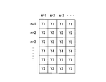
- the luminance signal Y (1,1) of the pixel (1,1) is Y1
- the luminance signal Y (2,1) of the pixel (2,1) is Y2
- the luminance signal Y ( 3 and 1) are defined as Y3
- the luminance signal Y (4,1) of the pixel (4,1) is defined as Y4
- the luminance signal of each pixel in the captured image is as shown in FIG.
- the color difference signal corresponding to the luminance signal Y (n, m) is expressed by either Cb (n, m) or Cr (n, m) in the following equation depending on the filter arrangement.
- the color difference signal when the combination of adjacent pixels in the vertical direction (each column) among the 2 ⁇ 2 pixels that generate the luminance signal Y is Mg and Cy and Gr and Ye is as follows ( 6) It is expressed by the formula.
- Cb [Mg + Cy]-[Gr + Ye] (6)
- the color difference signal C (1,1) corresponding to Y (1,1) is It becomes as follows.
- C (1,1) [Mg1 + Cy1] ⁇ [Gr1 + Ye1]
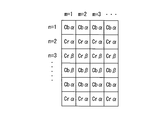
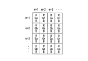
- a predetermined synchronization process is performed on the color difference signal, and as shown in FIG. Are assigned three image signals Y, Cb, and Cr.
- the subscripts 1 to 4 following Cb and Cr indicate the luminance signal corresponding to each color difference signal.
- the luminance / color noise that is a problem in the present embodiment is caused by the fact that the spectral characteristics differ depending on the position of the captured image. Therefore, in the image signal correction method according to the present embodiment, a set of horizontal lines having the same spectral characteristics of luminance and color difference signals is defined as one group, the entire image is divided into four groups, and each group is divided. In addition, luminance and color noise are reduced by correcting each signal.
- one of the four divided groups is a reference group (first group), the remaining three groups are target groups (second groups), and the signal values (Y, Cb) of the target groups are set.
- , Cr) is created for each target group so as to substantially match the signal values (Y, Cb, Cr) of the reference group. Then, by correcting the signal value of each target group using this correction matrix, the signals of each group are substantially matched. Thereby, it is possible to simultaneously correct luminance noise and color noise of the entire captured image.
- Expression (8) shows an example of a correction expression using a correction matrix.
- Y, Cb, and Cr are signal values before correction
- Y c , Cb c , and Cr c are signal values after correction.
- Y i T , Cb i T , and Cr i T represent signal values output from the reference group
- Y i o , Cb i o , and Cr i o are signals output from the target group.
- N represents the number of color charts.
- the correction coefficient is the spectral characteristics of each signal of the target group. Therefore, luminance noise and color noise can be corrected without depending on the subject.
- the correction matrix includes at least one type of image signal value in the reference group, that is, one of the luminance signal Y and the color difference signals Cb and Cr, and all types in the target group, that is, the luminance signal Y and the color difference signal.
- the relationship between Cb and Cr image signal values is defined.
- the correction matrix is a correction matrix in which at least one image signal value for each color chart among a plurality of types (luminance signal, color difference signal) is substantially matched between at least two groups.
- a correction matrix substantially matches the average spectral characteristics of the pixels belonging to the reference group and the average spectral characteristics of the pixels belonging to the target group if the image signal of the target group of the color image is corrected by the correction matrix. It can be made to.
- the correction matrix is calculated by taking the number of color charts necessary for ensuring the performance according to the predicted subject and performing the same calculation. Is possible.
- the correction matrix is calculated as a linear 3 ⁇ 3 matrix.
- the correction matrix includes a high-order term obtained by multiplying Y i o , Cb i o , and Cr i o by the least square method. It is also possible to apply the calculated nonlinear matrix coefficients. The calculation of the nonlinear matrix coefficient is performed as follows, for example.
- b 11 to b 36 represent coefficients of a 3 ⁇ 6 nonlinear matrix.
- B 11 to b 36 when the three equations (10) are minimized are calculated.
- the 3 ⁇ 6 nonlinear matrix coefficient is calculated in the above equation (10), it is also possible to apply a 3 ⁇ 9 nonlinear matrix coefficient including higher-order terms.
- the color difference signal is synchronized so that the generation patterns of the luminance noise and the color noise are the same.
- correction by the same method is possible by grouping a set of pixels having the same spectral characteristics of the luminance signal and the color difference signal as one group. .
- each color filter and the method of generating luminance / color difference signals change, the generation pattern of luminance / color noise due to the influence of mixed colors may change, and each group does not necessarily become a set of horizontal lines. Even in such a case, it is possible to perform grouping in advance according to the spectral characteristics of each pixel from the filter array and the calculation formula of each signal, and to perform correction by the same method.
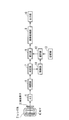
- FIG. 8 is a block diagram showing a schematic configuration of the imaging apparatus and the image processing apparatus according to the first embodiment of the present invention.
- the subject image formed by the lens system 2 is formed on the image pickup surface of the image pickup device 3, and after passing through each color filter, is converted into an electric signal.
- the image pickup device 3 is a single CCD having the color difference line sequential complementary color filter shown in FIG. Therefore, the image signal output from the image sensor 3 is a YCbCr signal.
- the image signal thus obtained is converted into a digital signal by the A / D converter 5.
- the interpolation unit 6 generates a YCbCr signal for each pixel on the image by a known synchronization process and outputs the YCbCr signal to the determination unit 7.
- the determination unit 7 determines which group of the plurality of groups determined according to the arrangement of the color filters belongs to each pixel of the input image.
- the determination unit 7 holds information in which the position of each pixel on the captured image is associated with the group, and groups each pixel based on this information.
- the signal of each grouped pixel is output to the correction unit 8.
- the lens system 2, the image sensor 3, and the A / D conversion unit 5 are removed from the image processing apparatus.
- the storage unit 13 stores a plurality of correction matrices in association with groups.
- the control unit 11 provides the selection unit 12 with information on the group to which each pixel input to the correction unit 8 belongs.
- the selection unit 12 reads out the correction matrix corresponding to the group to which the pixel belongs from the plurality of correction matrices stored in the storage unit 13, and outputs the read out correction matrix to the correction unit 8.
- the correction unit 8 corrects the pixel signal values (luminance signal and color difference signal) output from the determination unit 7 using the correction matrix given from the selection unit 12.
- the correction unit 8 corrects the pixel value of the type to be corrected using the correction matrix and all types of signal values in the pixel.
- all types of signal values constituting each pixel can be corrected. That is, in the present embodiment, both the luminance signal and the color difference signal are corrected.
- all kinds of signal values (( Here, correction is performed using a luminance signal and a color difference signal.
- the corrected signal value of each pixel is output to the image processing unit 9, subjected to predetermined image processing, then output to the output unit 10, and output as one image.
- each pixel is divided into a plurality of groups determined according to the arrangement of the complementary color filters.
- Each pixel value is corrected using a different correction matrix.
- the correction matrix of each group is calculated so that the signal values of all the groups become substantially the same value, so that the signal values after correction using the correction matrix can be made uniform. It becomes. Thereby, it is possible to eliminate variation in spectral characteristics over the entire image, and it is possible to eliminate noise caused by color mixing.
- processing by hardware is assumed, but it is not necessary to be limited to such a configuration.
- a configuration in which an image signal from the image sensor 3 is input to a PC as raw data without processing and processed by software separately is also possible.
- the program for realizing the image signal correction method according to the present embodiment is recorded on a computer-readable recording medium, and the CPU executes the program recorded on the recording medium, so that The image signal correction method is realized.
- FIG. 9 is a flowchart showing the procedure of the image signal correction method according to the first embodiment of the present invention.
- step SA2 unprocessed color image signals and information on a plurality of predetermined groups are input in step SA1.
- step SA2 a synchronization process is performed on the color image signal obtained in step SA1, and a luminance signal Y and color difference signals Cb and Cr are generated for all pixels of the color image.
- step SA3 a signal value for one pixel is read out from the image signal for one frame generated in step SA2.
- step SA4 which group of the plurality of groups in which the one pixel is captured in step SA1 is selected. It is judged whether it belongs to.
- step SA5 a correction matrix corresponding to the group to which this pixel belongs is selected from a plurality of previously stored matrices.
- step SA6 the signal value of the pixel is corrected using the selected correction matrix.
- step SA7 it is determined whether or not correction has been completed for all pixels for one frame.
- step SA7 when the above-described signal correction has not been completed for one frame of pixels ("NO” in step SA7), the process returns to step SA3 to read a new signal value for one pixel, and the signal of this pixel The above-described correction process is performed on the value. On the other hand, when the signal correction has been completed for one frame of pixels (“YES” in step SA7), the processing is terminated.
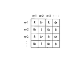
- FIG. 10 shows an example of primary color filters arranged two-dimensionally on a color CCD.
- Three primary colors of red (R), green (G), and blue (B) are arranged in a Bayer array.
- the green color filter is expressed as Gr and Gb due to the difference between the color filters adjacent in the horizontal direction, and these two have different spectral characteristics due to the influence of the color mixture.
- one of the three divided groups is a reference group
- the remaining two groups are target groups
- a correction matrix that substantially matches the signal value of the target group with the signal value of the reference group is set for each target group. To create. Then, by correcting the signal value of each target group using this correction matrix, the signals of each group are substantially matched.
- R, G, and B are signal values before correction
- R c , G c , and B c are signal values after correction.
- the correction matrix calculation method used in the equation (11) the method according to the first embodiment described above can be used.
- the imaging apparatus shown in FIG. 8 when a primary color filter is adopted instead of the single-plate CCD having the color difference line sequential complementary filter, the signal values of the pixels belonging to each group are converted into a correction matrix unique to that group. As in the case of using the color difference line sequential complementary color filter, it is possible to eliminate luminance noise and color noise.
Landscapes
- Engineering & Computer Science (AREA)
- Multimedia (AREA)
- Signal Processing (AREA)
- Health & Medical Sciences (AREA)
- Biomedical Technology (AREA)
- General Health & Medical Sciences (AREA)
- Color Television Image Signal Generators (AREA)
Priority Applications (1)
| Application Number | Priority Date | Filing Date | Title |
|---|---|---|---|
| US12/835,953 US8692910B2 (en) | 2008-01-23 | 2010-07-14 | Image processing device, image signal correction method, correction matrix calculation method, and imaging device |
Applications Claiming Priority (2)
| Application Number | Priority Date | Filing Date | Title |
|---|---|---|---|
| JP2008012983A JP5242180B2 (ja) | 2008-01-23 | 2008-01-23 | 画像処理装置、画像信号補正方法、補正マトリクス算出方法及び撮像装置 |
| JP2008-012983 | 2008-01-23 |
Related Child Applications (1)
| Application Number | Title | Priority Date | Filing Date |
|---|---|---|---|
| US12/835,953 Continuation US8692910B2 (en) | 2008-01-23 | 2010-07-14 | Image processing device, image signal correction method, correction matrix calculation method, and imaging device |
Publications (1)
| Publication Number | Publication Date |
|---|---|
| WO2009093588A1 true WO2009093588A1 (ja) | 2009-07-30 |
Family
ID=40901096
Family Applications (1)
| Application Number | Title | Priority Date | Filing Date |
|---|---|---|---|
| PCT/JP2009/050809 Ceased WO2009093588A1 (ja) | 2008-01-23 | 2009-01-21 | 画像処理装置、画像信号補正方法、補正マトリクス算出方法及び撮像装置 |
Country Status (3)
| Country | Link |
|---|---|
| US (1) | US8692910B2 (enExample) |
| JP (1) | JP5242180B2 (enExample) |
| WO (1) | WO2009093588A1 (enExample) |
Cited By (1)
| Publication number | Priority date | Publication date | Assignee | Title |
|---|---|---|---|---|
| US9507123B2 (en) | 2013-07-12 | 2016-11-29 | Panasonic Intellectual Property Management Co., Ltd. | Imaging apparatus |
Families Citing this family (4)
| Publication number | Priority date | Publication date | Assignee | Title |
|---|---|---|---|---|
| CN103621070B (zh) | 2011-06-30 | 2015-05-20 | 富士胶片株式会社 | 摄像装置及摄像装置的控制方法 |
| JP6034197B2 (ja) * | 2011-08-25 | 2016-11-30 | パナソニック インテレクチュアル プロパティ コーポレーション オブ アメリカPanasonic Intellectual Property Corporation of America | 画像処理装置、3次元撮像装置、画像処理方法、および画像処理プログラム |
| US9030580B2 (en) * | 2013-09-28 | 2015-05-12 | Ricoh Company, Ltd. | Color filter modules for plenoptic XYZ imaging systems |
| CN117616749A (zh) * | 2022-06-17 | 2024-02-27 | 北京小米移动软件有限公司 | 相机模组的色彩校正矩阵标定方法及装置 |
Citations (4)
| Publication number | Priority date | Publication date | Assignee | Title |
|---|---|---|---|---|
| JP2001320722A (ja) * | 2000-05-12 | 2001-11-16 | Canon Inc | 信号処理装置及び信号処理方法 |
| JP2005278004A (ja) * | 2004-03-26 | 2005-10-06 | Fuji Photo Film Co Ltd | 色シェーディング補正方法および固体撮像装置 |
| JP2007053479A (ja) * | 2005-08-16 | 2007-03-01 | Fujifilm Holdings Corp | 撮像装置の信号処理方法及び撮像装置 |
| JP2007228155A (ja) * | 2006-02-22 | 2007-09-06 | Olympus Imaging Corp | 電子撮像装置及び電子撮像方法 |
Family Cites Families (7)
| Publication number | Priority date | Publication date | Assignee | Title |
|---|---|---|---|---|
| JPH06292224A (ja) * | 1993-03-30 | 1994-10-18 | Sony Corp | 色信号補正装置及び方法 |
| JP3648316B2 (ja) * | 1996-01-18 | 2005-05-18 | チノン株式会社 | 撮像装置 |
| JPH09219866A (ja) * | 1996-02-13 | 1997-08-19 | Toshiba Corp | カラー固体撮像装置 |
| JP3755921B2 (ja) | 1996-02-29 | 2006-03-15 | 株式会社コダックデジタルプロダクトセンター | 撮像デバイスのラインノイズ除去方法及びそれを用いたラインノイズ除去装置 |
| JP5108172B2 (ja) | 2000-09-06 | 2012-12-26 | 株式会社ニコン | 画像データサイズ変換処理装置、電子スチルカメラ、および画像データサイズ変換処理用記録媒体 |
| JP4581633B2 (ja) * | 2004-10-29 | 2010-11-17 | 富士フイルム株式会社 | 色信号補正方法、装置及びプログラム |
| US7643072B2 (en) | 2005-08-16 | 2010-01-05 | Fujifilm Corporation | Signal processing method for image capturing apparatus, and image capturing apparatus including calculating image transfer efficiency |
-
2008
- 2008-01-23 JP JP2008012983A patent/JP5242180B2/ja active Active
-
2009
- 2009-01-21 WO PCT/JP2009/050809 patent/WO2009093588A1/ja not_active Ceased
-
2010
- 2010-07-14 US US12/835,953 patent/US8692910B2/en active Active
Patent Citations (4)
| Publication number | Priority date | Publication date | Assignee | Title |
|---|---|---|---|---|
| JP2001320722A (ja) * | 2000-05-12 | 2001-11-16 | Canon Inc | 信号処理装置及び信号処理方法 |
| JP2005278004A (ja) * | 2004-03-26 | 2005-10-06 | Fuji Photo Film Co Ltd | 色シェーディング補正方法および固体撮像装置 |
| JP2007053479A (ja) * | 2005-08-16 | 2007-03-01 | Fujifilm Holdings Corp | 撮像装置の信号処理方法及び撮像装置 |
| JP2007228155A (ja) * | 2006-02-22 | 2007-09-06 | Olympus Imaging Corp | 電子撮像装置及び電子撮像方法 |
Cited By (1)
| Publication number | Priority date | Publication date | Assignee | Title |
|---|---|---|---|---|
| US9507123B2 (en) | 2013-07-12 | 2016-11-29 | Panasonic Intellectual Property Management Co., Ltd. | Imaging apparatus |
Also Published As
| Publication number | Publication date |
|---|---|
| US20100277626A1 (en) | 2010-11-04 |
| US8692910B2 (en) | 2014-04-08 |
| JP5242180B2 (ja) | 2013-07-24 |
| JP2009177418A (ja) | 2009-08-06 |
Similar Documents
| Publication | Publication Date | Title |
|---|---|---|
| TWI504277B (zh) | 影像感測裝置、影像感測器的操作方法、串音修正方法以及偽色誤差修正方法 | |
| JP5672776B2 (ja) | 画像処理装置、および画像処理方法、並びにプログラム | |
| EP2211554B1 (en) | Image processing device, image processing method, and image processing program | |
| JP2009147489A (ja) | 固体撮像素子及びそれを用いた撮像装置 | |
| JP2008070853A (ja) | 画像配列データの補償方法 | |
| CN103416067B (zh) | 摄像装置 | |
| JP6074813B2 (ja) | カラーフィルタアレイ及び撮像素子 | |
| JP2000023174A (ja) | 画像処理装置及び画像処理方法 | |
| JP5242180B2 (ja) | 画像処理装置、画像信号補正方法、補正マトリクス算出方法及び撮像装置 | |
| EP2031881B1 (en) | Image pickup device and signal processing method | |
| KR100450132B1 (ko) | 화상처리장치 및 처리방법 | |
| JP5600813B2 (ja) | 画像処理装置及び撮像装置 | |
| JP5673186B2 (ja) | 撮像装置及び撮像装置の補間処理方法 | |
| JP2013172218A (ja) | 撮像装置、画像処理方法およびプログラム | |
| JP4486874B2 (ja) | 多分割読出ccdの補正近似直線群情報生成方法及び多分割読出ccdの補正処理装置製造方法 | |
| JP2009290568A (ja) | 撮像装置 | |
| JP5106221B2 (ja) | 撮像装置 | |
| US6674465B1 (en) | Image processing apparatus which does not generate a false signal even if unevenness of spectral sensitivities of the color filter occurs | |
| JP2007088640A (ja) | 固体撮像装置及び画像信号処理方法 | |
| KR20120042631A (ko) | 촬상 장치, 신호 처리 방법, 및 프로그램 | |
| JP2013219627A (ja) | 撮像装置及び撮像装置の制御方法 | |
| JP2009017513A (ja) | 撮像装置 | |
| JPH06197362A (ja) | 撮像装置 | |
| JP2008178010A (ja) | 撮像装置及び撮像装置の駆動方法 | |
| JP2006222537A (ja) | 画像処理装置及びその画像処理方法 |
Legal Events
| Date | Code | Title | Description |
|---|---|---|---|
| 121 | Ep: the epo has been informed by wipo that ep was designated in this application |
Ref document number: 09704339 Country of ref document: EP Kind code of ref document: A1 |
|
| NENP | Non-entry into the national phase |
Ref country code: DE |
|
| 122 | Ep: pct application non-entry in european phase |
Ref document number: 09704339 Country of ref document: EP Kind code of ref document: A1 |