WO2009090845A1 - 書類処理進捗管理システム - Google Patents
書類処理進捗管理システム Download PDFInfo
- Publication number
- WO2009090845A1 WO2009090845A1 PCT/JP2008/073620 JP2008073620W WO2009090845A1 WO 2009090845 A1 WO2009090845 A1 WO 2009090845A1 JP 2008073620 W JP2008073620 W JP 2008073620W WO 2009090845 A1 WO2009090845 A1 WO 2009090845A1
- Authority
- WO
- WIPO (PCT)
- Prior art keywords
- progress
- tag
- information
- control circuit
- work
- Prior art date
- Legal status (The legal status is an assumption and is not a legal conclusion. Google has not performed a legal analysis and makes no representation as to the accuracy of the status listed.)
- Ceased
Links
Images












Classifications
-
- G—PHYSICS
- G06—COMPUTING OR CALCULATING; COUNTING
- G06K—GRAPHICAL DATA READING; PRESENTATION OF DATA; RECORD CARRIERS; HANDLING RECORD CARRIERS
- G06K17/00—Methods or arrangements for effecting co-operative working between equipments covered by two or more of main groups G06K1/00 - G06K15/00, e.g. automatic card files incorporating conveying and reading operations
Definitions
- the present invention relates to a document processing progress management system provided with a tag label producing device for producing a RFID label having an RFID circuit element having an IC circuit unit for storing information and a tag side antenna for transmitting and receiving information.
- Patent Document 1 discloses a conventional technique of the RFID system.
- a RFID label RFID tag
- tag identification information tag identifier
- a plurality of readers sensors
- the locations of these readers are also registered in the database in advance.
- An object of the present invention is to provide a document processing progress management system capable of centrally managing the progress status of a plurality of work procedures and managing the progress status according to a specific case even when a specific case related to the progress occurs. There is to do.
- the document processing progress management system is a document processing progress of at least one event that is completed in advance by a plurality of work procedures set along a predetermined time interval.
- a database that stores and holds progress related information related to a progress schedule
- a first wireless tag that stores unique case information corresponding to a unique case related to the progress of the event
- a reader that acquires information via wireless communication, and when the reader acquires the unique case information of the first wireless tag, the progress-related information stored and held in the database is associated with the unique case
- database update means for changing is a document processing progress of at least one event that is completed in advance by a plurality of work procedures set along a predetermined time interval.
- progress-related information relating to the progress or schedule of document processing of at least one event is stored and held in a database.
- the progress related information corresponding to each event in this database is updated according to the actual progress of each event, it is possible to centrally manage the progress of document processing in each event using the progress related information. It becomes possible.
- the database update means can acquire the specific case information from the first wireless tag via the wireless communication by the reader.
- the progress related information stored and held in the database is changed to correspond to the unique case.
- the progress status of the event can be managed using the changed progress-related information while corresponding to the specific case.
- the first invention of the present application it is possible to centrally manage the progress of document processing in at least one event, and even when a specific case related to the progress occurs, the progress is made while responding to the specific case.
- the situation can be managed.
- the document processing progress management system is the document processing progress management system according to the first aspect, wherein when the reader acquires the unique case information of the first wireless tag, at least one unique case among a plurality of preset unique cases is obtained.
- the database further includes a unique case selection unit capable of selecting a case, and the database update unit changes the progress-related information stored and held in the database according to the content of the specific case selected by the specific case selection unit. It is characterized by doing.
- the unique case selection means selects at least one unique case from a plurality of preset unique cases, and this selection
- the database updating means changes the progress related information stored and held in the database according to the contents of the specific case.
- the database update unit acquires the specific case information of the first wireless tag with the reader, On the basis of the above, it is characterized by having schedule change means for changing schedule information relating to the length of the time section of the work procedure included in the progress related information stored and held in the database.
- the schedule changing means when the specific case information is acquired from the first wireless tag by the reader, the schedule changing means obtains schedule information regarding the length of the time division of the work procedure included in the progress related information stored and held in the database. change. As a result, even if it is necessary to change the originally scheduled schedule before or during the progress of the event, the progress of document processing in the event can be managed while corresponding to the changed schedule. .
- the unique case selection unit Based on a selection result, there is provided order change means for changing order information related to the order of the work procedures included in the progress related information stored and held in the database so as to correspond to the specific case.
- the order changing means uses the order information regarding the order of the work procedures included in the progress related information stored and held in the database as the unique case. Change to correspond.
- the order of document processing in the event can be managed while changing the order of the work procedures correspondingly.
- the document processing progress management system is the document processing progress management system according to the fourth aspect, wherein the order changing means changes the order information so that the progress returns from the corresponding work procedure to the preceding work procedure in the predetermined order. It has a return means.
- the return means when the unique case information is acquired from the first wireless tag by the reader, the return means changes the order information so that the progress returns from the corresponding work procedure to the previous work procedure in the predetermined order. .
- the progress of document processing in the event can be managed while returning the work procedure correspondingly.
- the order changing means skips the corresponding work procedure so that the progress proceeds to a subsequent work procedure in the predetermined order. It has a skip means for changing the order information.
- the skip means when the unique case information is acquired from the first wireless tag by the reader, the skip means skips the corresponding work procedure and advances the order information to the subsequent work procedure in the predetermined order. change.
- the progress of document processing in the event can be managed while skipping the work procedure correspondingly. it can.
- the document processing progress management system is the document processing progress management system according to the sixth aspect, wherein when the order change means changes the order information by the skip means, the work skipped from the corresponding work procedure as necessary. It has a skip complementing means for changing the order information so that the progress returns to the procedure.
- the work procedure is skipped from the corresponding work procedure by the skip complement means as necessary.
- the order information is changed so that the progress returns to the work procedure.
- the work procedure was skipped during the progress of the event and proceeded to the next work procedure, but when it was necessary to execute the skipped work procedure thereafter, the progress was returned to the work procedure skipped correspondingly.
- the progress of document processing in the event can be managed.
- the document processing progress management system is characterized in that, in the sixth or seventh aspect of the invention, when the order information is changed by the skip means, the information processing means further notifies the operator to that effect. To do.
- the notifying means when the order information is changed so that the corresponding work procedure is skipped by the skip means and the progress proceeds to the next work procedure, the notifying means notifies the operator to that effect. As a result, the work procedure was skipped during the progress of the event and proceeded to the next work procedure, but when the skipped work procedure needs to be executed after that, the operator forgets to execute the work procedure. Can be prevented.
- the document processing progress management system is the document processing progress management system according to any one of the second to eighth aspects, wherein the database update unit acquires the specific case information of the first wireless tag with the reader. Based on the selection result of the selection means, it has a state information adding means for adding work state information representing a work state in the corresponding work procedure to the progress related information stored and held in the database.
- the state information adding means when the unique case information is acquired from the first wireless tag by the reader, stores the work state information indicating the work state in the corresponding work procedure in the database and stores the progress related information. Append to This makes it possible to manage the progress of document processing in the event while the work procedure is put on hold in response to a need to hold the work procedure for some reason during the progress of the event. .
- a document processing progress management system is the document processing progress management system according to any one of the first to ninth aspects, wherein the event-related information is created corresponding to the work procedure for each event and corresponds to the event or the work procedure.
- the database update means stores the progress related information stored and held in the database when the event related information of the second wireless tag is acquired by the reader. It changes so that progress may progress to the said work procedure.
- the database update means stores the progress-related information stored and held in the database. Is changed so that the progress proceeds to a predetermined work procedure.
- the progress-related information corresponding to each event in the database is updated according to the actual progress status of each event, so the progress status of document processing in each event is centrally managed using the progress-related information. be able to.
- the document processing progress management system is characterized in that, in the tenth aspect, the document processing progress management system further comprises invalidating means for invalidating the second wireless tag so as not to update the progress.
- the database updating means stores the progress related information stored and held in the database even if the event related information of the second wireless tag is acquired by the reader. Do not update information. Thereby, when it becomes necessary to stop the progress of the event for some reason during the progress of the event, the progress can be stopped correspondingly, and the progress can be prevented from progressing thereafter.
- the document processing progress management system is the tenth or eleventh aspect of the present invention, wherein the progress of document processing in a plurality of the events is defined as the progress of a single event representing the plurality of events.
- the apparatus further includes representative tag determining means for determining a representative wireless tag corresponding to the single representative event.
- the representative tag determination means determines the representative wireless tag corresponding to a single event representing a plurality of events, thereby centrally managing the progress of document processing in a plurality of events as the progress of a single event. Can do.
- the representative tag determining means converts the plurality of second wireless tags respectively corresponding to the plurality of events into a single representative event. It is characterized by being unified as a corresponding wireless tag.
- the representative tag determining means unifies the plurality of second wireless tags corresponding to a plurality of events by the wireless tag determining means as wireless tags corresponding to a single representative event.
- the database updating means updates the progress related information of the corresponding single event even when the event related information of any one of the plurality of unified second wireless tags is read by the reader. To do. Therefore, when it is necessary to manage the progress of a plurality of events as a single event for some reason, it is possible to manage the progress of document processing in a single event corresponding to this.
- the representative tag determining means determines the representative wireless tag from the plurality of second wireless tags respectively corresponding to the plurality of events.
- the other second wireless tag is invalidated.
- the representative tag determining means determines a representative wireless tag from a plurality of second wireless tags corresponding to a plurality of events, and invalidates the other second wireless tags.
- the database update means updates the progress related information of the event corresponding to the representative wireless tag, and the invalidated second wireless tag
- the progress related information of the corresponding event is not updated. In this way, if it becomes necessary to manage the progress of multiple events as a single event for some reason, the progress of document processing in a single event should be managed accordingly. Can do.
- a document processing progress management system is the twelfth aspect of the present invention, for carrying a tag medium on which an RFID circuit element having an IC circuit section for storing information and a tag side antenna for transmitting and receiving information is arranged.
- Transport means printing means for performing predetermined printing on a tag medium transported by the transport means or a print medium bonded thereto, and tag access means for accessing the RFID circuit element
- the apparatus further comprises a tag label creating device for creating a wireless tag and a second wireless tag, wherein the representative tag determining means invalidates the plurality of second wireless tags respectively corresponding to the plurality of events, and the plurality of events. Or outputting a creation instruction signal for creating a single third wireless tag storing event-related information corresponding to the work procedure to the tag label producing device And features.
- the representative tag determining means invalidates the plurality of second wireless tags respectively corresponding to the plurality of events and creates a single third wireless tag corresponding to the plurality of events.
- a production instruction signal is output to the tag label production apparatus.
- the tag medium is conveyed by the conveying means, the predetermined printing is performed on the tag medium (or the medium to be printed) by the printing means, and the RFID tag circuit element provided in the tag medium is subjected.
- Access (information reading or information writing) by wireless communication is performed by the tag access means, and a third wireless tag is created.
- the database update means updates the progress related information of the corresponding single event when the event related information of the generated third wireless tag is acquired by the reader. In this way, if it becomes necessary to manage the progress of multiple events as a single event for some reason, the progress of document processing in a single event should be managed accordingly. Can do.
- the document processing progress management system is characterized in that, in any one of the first to fifteenth aspects, the database stores and holds information relating to the progress of document processing at the time of preparing the specification of the patent application. To do.
- the sixteenth invention of the present application it is possible to centrally manage the progress of document processing of specifications, etc. in a plurality of patent applications, and to change schedules (such as urgent applications) and work procedures (modified specifications) Even if a special case regarding progress occurs, such as re-delivery of the business), the progress status can be managed in correspondence with the special case.
- the progress status of a plurality of work procedures can be centrally managed, and the progress status can be managed according to the specific case even when a specific case related to the progress occurs.
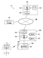
- FIG. 1 is a system configuration diagram showing a patent progress management system provided with a tag label producing apparatus of this embodiment.
- This patent progress management system PS shown in FIG. 1 includes a tag side antenna 151 for transmitting / receiving RFID tag information and an RFID circuit element To that is connected to the IC circuit unit 150 and can store RFID tag information.
- a tag label producing device 100 for producing a RFID label T having (see FIG. 4 described later), a server 200 and a PC (Personal Computer) 300 connected to the tag label producing device 100 via a wired or wireless communication line NW;
- the reader 300 is connected to the PC 300 and performs wireless communication with the created RFID label T and reads the RFID tag information from the IC circuit unit 150 of the RFID circuit element To.
- the PC 300 includes a display unit 301 such as a liquid crystal display and an operation unit 302 such as a keyboard and a mouse, and an operator browses information via the display unit 301 when performing each work process described later. Information can be input using the operation unit 302.
- a display unit 301 such as a liquid crystal display
- an operation unit 302 such as a keyboard and a mouse
- Information can be input using the operation unit 302.
- a plurality of PCs 300 are connected to the communication line NW, and operators of each PC 300 share the server 200 and the tag label producing apparatus 100. It is possible.
- FIG. 2 is a system configuration diagram showing the system configuration of the patent progress management system PS.
- the arrow shown in a figure shows an example of the flow of a signal, and does not limit the flow direction of a signal.
- the server 200 includes a control circuit 201 that controls the entire server 200, and an interface 202 that performs network communication between the control circuit 201 and the tag label producing apparatus 100 and the PC 300 via a communication line NW.
- Item information (invention name, representative inventor, etc.) of each patent application item (event), progress related information on progress or schedule of document processing, these item information and progress related information, and tag of RFID circuit element
- the database 203 (consisting of a hard disk or the like) in which information such as association information with ID (tag identification information) is stored.
- the progress related information stored and held in the database 203 includes schedule information related to the length of the time division of each work process of each patent case, and information indicating the progress status of each patent case. 201 is updated (details will be described later).
- the PC 300 inputs and outputs information to and from the display unit 301 for performing various displays, the operation unit 302 for an operator to input various operations, and the high-frequency circuit 402 of the reader 400, and controls the entire PC 300. And a control circuit 303, and an interface 304 for performing network communication with the control circuit 201 of the tag label producing apparatus 100 and the server 200 via the communication line NW.
- the reader 400 transmits a signal by wireless communication with the tag-side antenna 151 of the RFID circuit element To included in the RFID label T (including a later-described main tag label Ta, subordinate tag label Tc, and privileged tag label Ti). And the high-frequency circuit 402 that accesses the IC circuit unit 150 of the RFID circuit element To via the antenna 401 by wireless communication and processes the signal read from the RFID circuit element To. And have.
- FIG. 3 is a configuration diagram showing a detailed configuration of the tag label producing apparatus 100.
- the arrow shown in a figure shows an example of the flow of a signal, and does not limit the flow direction of a signal.
- the tag label producing apparatus 100 is a tag tape roll 104 (originally spiral, but simplified and concentrically shown) wound around a tag tape 103 (tag medium) provided with RFID circuit elements To at predetermined intervals.
- a tag tape roll holder portion 110 that can be attached / detached (or a cartridge equipped with the tag tape roll 104 can be attached / detached), and the tag tape 103 that is fed out from the tag tape roll 104 corresponds to the RFID circuit element To.
- a print head 105 (printing means) that performs predetermined printing in the area, an antenna 106 that transmits and receives information by wireless communication with the RFID circuit element To, the high-frequency circuit 101 and the control circuit 102, and the server 200. And an interface for performing network communication with the PC 300 via the communication line NW.
- the cutter 107 Opposite to the print head 105, the cutter 107 that cuts the tag tape 103 that has finished printing on the tag tape 103 and writing the information on the RFID circuit element To to a predetermined length and forms the RFID label T And a conveying device 109 (conveying means) that conveys the tag tape 103 under the control of the control circuit 102.
- the high frequency circuit 101 and the control circuit 102 generate access information to the IC circuit unit 150 of the RFID circuit element To and transmit it to the RFID circuit element To via the antenna 106, and the IC circuit part of the RFID circuit element To Information is written to 150.
- the high-frequency circuit 101 and the antenna 106 constitute tag access means for performing wireless communication access to the RFID tag circuit element described in the claims.
- the control circuit 102 of the tag label producing apparatus 100, the control circuit 201 of the server 200, and the control circuit 303 of the PC 300 are not particularly shown, but are so-called microcomputers, which are a central processing unit such as a CPU, ROM, and RAM.
- the predetermined processing procedure is performed according to a program stored in advance in the ROM while using the temporary storage function of the RAM.
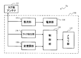
- FIG. 4 is a functional block diagram showing a functional configuration of the RFID circuit element To.
- the arrow shown in a figure shows an example of the flow of a signal, and does not limit the flow direction of a signal.
- the RFID circuit element To includes the tag antenna 151 that transmits and receives signals without contact with the device antenna (the antenna 106 of the RFID label producing apparatus 100 and the antenna 401 of the reader 400), and the tag side.
- the IC circuit unit 150 is connected to the antenna 151.
- the IC circuit unit 150 includes a rectification unit 153 that rectifies the interrogation wave received by the tag-side antenna 151, a power supply unit 154 that accumulates the energy of the interrogation wave rectified by the rectification unit 153, and serves as a drive power source.
- a clock extraction unit 156 that extracts a clock signal from the interrogation wave received by the tag side antenna 151 and supplies the clock signal to the control unit 155, a memory unit 157 that can store a predetermined information signal, and a connection to the tag side antenna 151
- the modulation / demodulation unit 158, and the control unit 155 for controlling the operation of the RFID circuit element To through the rectification unit 153, the clock extraction unit 156, the modulation / demodulation unit 158, and the like.
- the modulation / demodulation unit 158 demodulates the interrogation wave received from the tag-side antenna 151 from the device-side antenna, modulates the reply signal from the control unit 155, and transmits the response signal from the tag-side antenna 151. .
- the control unit 155 interprets the received signal demodulated by the modulation / demodulation unit 158, generates a return signal based on the information signal stored in the memory unit 157, and performs basic control such as returning by the modulation / demodulation unit 158. Execute proper control.
- the clock extraction unit 156 extracts a clock component from the received signal, and supplies a clock corresponding to the frequency of the clock component to the control unit 155.
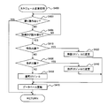
- FIG. 5 is a flowchart showing a control procedure performed by the control circuit 201 of the server 200.
- step S10 the control circuit 201 determines whether or not the tag ID has been read from the RFID label T. Specifically, the control circuit 201 transmits a control signal to the control circuit 303 of the PC 300 via the communication line NW, and the IC of the RFID tag circuit element To of the RFID label T via the high frequency circuit 402 and the antenna 401 of the reader 400. A reading signal for reading the tag ID stored in the circuit unit 150 is transmitted. Thereafter, the reply signal returned from the RFID circuit element To corresponding to the read signal is received via the antenna 401 and taken into the control circuit 303 via the high frequency circuit 402. This step is repeated until the control circuit 303 acquires the tag ID. If acquired, the determination is satisfied, and the routine goes to the next Step S15.
- step S15 the control circuit 201 receives and acquires the tag ID acquired from the RFID label T by the control circuit 303 of the PC 300 in step S15 via the communication line NW.
- Step S20 the control circuit 201 determines whether or not the RFID label T related to the tag ID acquired in Step S15 is the privileged tag label Ti.
- the privileged tag label Ti (first wireless tag) is a tag ID (single case information) corresponding to a specific case (schedule change, return of work process, etc., details will be described later) related to the progress of each patent case.
- the RFID tag label includes the RFID circuit element To stored in the memory unit 157 of the IC circuit unit 150.
- the privileged tag label Ti may be created by the tag label creating apparatus 100 included in the patent progress management system PS or may be created outside the system.
- the tag ID of the privileged tag label Ti is stored and held in the database 203 in association with the specific case, and the control circuit 201 searches the database 203 based on the tag ID acquired in step S15, and the wireless tag label T Is a privileged tag label Ti.
- Step S1000 the routine goes to Step S1000 to perform the normal mode processing (details will be described later with reference to FIG. 6). reference). Then, the process proceeds to step S30.
- the determination is satisfied, and the process proceeds to the next step S2000 to perform the singular mode processing (see FIG. 15 described later for details). Then, the process proceeds to step S30.
- the control circuit 201 determines whether to end the work. Specifically, when the operator closes the software for performing the above work on the PC 300 or turns off the power of the PC 300, it is determined that the work is finished. In other cases, the determination is not satisfied and the routine returns to the previous step S10. On the other hand, when the operation end operation as described above is performed, the determination is satisfied and this flow is ended.
- FIG. 6 is a flowchart showing a detailed procedure of details of the normal mode processing in step S1000.
- the control circuit 201 determines whether or not the work mode is the “label issue” mode.
- the work mode in the present embodiment is a “label issuance” mode for creating the RFID label T, a “progress update” mode for progressing the work process (work procedure), and a “progress update” mode for displaying the progress. "Progress list display” mode.
- the control circuit 201 transmits a control signal to the control circuit 303 of the PC 300 via the communication line NW to display a mode selection screen (see FIG. 7 described later) on the display unit 301, thereby Is performed based on a mode selection signal input using the operation unit 302 of the PC 300 based on the screen.
- step S100 to perform label issuance processing for creating the RFID label T (see FIG. 8 described later). Thereafter, this routine is terminated.
- the determination is not satisfied, and the routine goes to the next step S1020.
- step S1020 the control circuit 201 determines whether or not the work mode is the “progress update” mode. When the “progress update” mode is selected, the determination is satisfied, and the process proceeds to step S200 to perform a progress update process for progressing the work process (see FIG. 12 described later). Thereafter, this routine is terminated. On the other hand, if the “progress update” mode is not selected, the determination is not satisfied, and the routine goes to the next step S1030.
- step S1030 the control circuit 201 determines whether or not the work mode is the “progress list display” mode.
- the determination is satisfied, and the process proceeds to step S300, and a progress list display process for transmitting progress information and the like is performed to cause the PC 300 to display the progress list (described later). (See FIG. 13). Thereafter, this routine is terminated.
- the “progress list display” mode is not selected, the determination is not satisfied and this routine is terminated.
- step S200 when the event related information of the second wireless tag is acquired by the reader described in the claims, the progress related information stored and held in the database progresses to a predetermined work procedure.
- the database update means for changing is configured.
- FIG. 7 is a diagram illustrating an example of a mode selection screen displayed on the display unit 301 of the PC 300 by the control circuit 201 in the normal mode process.
- FIG. 8 is a flowchart showing a detailed procedure of the label issuing process in step S100.
- step S110 the control circuit 201 determines whether or not the RFID label T to be issued corresponds to a new case. This determination is an input signal indicating that the control circuit 201 is a new case input by the operator using the operation unit 302 of the PC 300 (for example, input by pressing a “new registration” button displayed on the screen). This is performed depending on whether or not is received via the communication line NW. If an input signal has been received (in the case of new registration), the determination is satisfied, and the routine goes to the next Step S600.
- step S600 the control circuit 201 performs a main tag label issuing process for creating the first RFID label T (hereinafter referred to as “main tag label Ta”) when registering a new case (see FIG. 9 described later).
- the main tag label Ta is used by being attached to a folder corresponding to each patent case. Note that the folder stores various documents (requests, claims (hereinafter also referred to as “claimed manuscript”), specification manuscripts, etc.) of the corresponding patent case (for example, a bag). Then, this routine ends.
- step S700 the control circuit 201 creates a RFID label T (hereinafter referred to as “subordinate tag label Tc”) that is scheduled to be created after the creation of the main tag label Ta for the case in which the main tag label Ta has already been created.
- the sub-tag label issuing process is performed (see FIG. 10 described later).
- the sub tag label Tc is created for each patent case when the IP officer receives a complaint manuscript from the patent office and when receiving a manuscript manuscript, and is attached to the manuscript manuscript and the manuscript manuscript, respectively. Used. Then, this routine ends.
- the main tag label Ta and the sub tag label Tc are created for each event described in the claims corresponding to the work procedure, and store the event-related information corresponding to the event or the work procedure. Configure.
- FIG. 9 is a flowchart showing a detailed procedure of the main tag label issuing process in step S600.
- step S610 the control circuit 201 transmits a control signal to the control circuit 303 of the PC 300 via the communication line NW, and causes the display unit 301 to display a case information input screen.
- the case information input screen is a screen for inputting case information when an IP person in charge registers a new patent case.
- the IP number application identification information
- control circuit 201 inputs the case information input by the intellectual property person in charge using the operation unit 302 of the PC 300 while referring to the above-described case information input screen via the communication line NW.
- the control circuit 201 determines whether or not to issue the main tag label Ta. In this determination, the control circuit 201 uses an issuance command signal (for example, input by pressing an “issue” button displayed on the screen) input by the IP person using the operation unit 302 of the PC 300 to the communication line NW. This is performed depending on whether or not the message is received via. If the issue command signal is not received, the determination is not satisfied and the process returns to step S620. On the other hand, if the issue command signal is received, the determination is satisfied, and the routine goes to the next Step S640.
- an issuance command signal for example, input by pressing an “issue” button displayed on the screen
- step S640 the control circuit 201 sets a tag ID (event related information) to be written to the RFID circuit element To of the main tag label Ta to be created.
- This setting is performed by the control circuit 201 reading an appropriate ID from the tag ID database stored in the database 203.
- a database for tag ID setting may be provided separately from the database 203.
- step S650 the control circuit 201 creates print information to be printed on the main tag label Ta to be created.
- the main tag label Ta is printed with the tag label usage (in the case of the main tag label Ta, “for folder”), the intellectual property number, the representative inventor, the agent, the title of the invention, and the like.
- the print information includes these pieces of information.
- control circuit 201 transmits the tag ID set in step S640 and the printing information created in step S650 to the control circuit 102 of the tag label producing apparatus 100 via the communication line NW.
- step S670 the control circuit 201 transmits a main tag label production completion signal (see step S840 in FIG. 11 described later) transmitted from the control circuit 102 when the production of the main tag label Ta is completed in the tag label production apparatus 100 to the communication line NW. It is determined whether or not the message has been received via. This step is repeated until a main tag label creation completion signal is received. If received, the determination is satisfied, and the routine goes to the next Step S680.
- a main tag label production completion signal (see step S840 in FIG. 11 described later) transmitted from the control circuit 102 when the production of the main tag label Ta is completed in the tag label production apparatus 100 to the communication line NW. It is determined whether or not the message has been received via. This step is repeated until a main tag label creation completion signal is received. If received, the determination is satisfied, and the routine goes to the next Step S680.
- step S680 the control circuit 201 registers the tag ID set in step S640, the case information input in step S620, and the print information created in step S650 in the database 203 in association with each other.
- the control circuit 201 sets the tag IDs of the subordinate tag labels Tc to be produced after the production of the produced main tag label Ta, that is, the tag IDs of the two subordinate tag labels Tc for the claim manuscript and the specification manuscript.
- the tag IDs for the sub tag label Tc (hereinafter referred to as “sub tag ID” as appropriate) are set in the same manner, and the tag ID for the main tag label Ta (hereinafter referred to as “main tag ID” as appropriate) registered in step S680. are registered in the database 203 in association with each other. Then, this routine ends.
- FIG. 10 is a flowchart showing a detailed procedure of the slave tag label issuing process in step S700.
- step S710 the control circuit 201 determines whether or not a case for creating the sub tag label Tc has been selected from the registered cases. In this determination, the control circuit 201 displays a case selection signal (for example, a list of registered cases, which is input by the intellectual property person using the operation unit 302 of the PC 300, and the intellectual property person (Input by selecting a specific case) is performed depending on whether or not it is received via the communication line NW. This step is repeated until a case selection signal is received. If it is received, the determination is satisfied, and the routine goes to the next Step S720.
- a case selection signal for example, a list of registered cases, which is input by the intellectual property person using the operation unit 302 of the PC 300, and the intellectual property person (Input by selecting a specific case) is performed depending on whether or not it is received via the communication line NW. This step is repeated until a case selection signal is received. If it is received, the determination is satisfied, and the routine goes to the next Step S720.
- step S720 the control circuit 201 determines whether or not to issue the sub tag label Tc.
- the control circuit 201 uses an issuance command signal (for example, input by pressing an “issue” button displayed on the screen) input by the IP person using the operation unit 302 of the PC 300 to the communication line NW. This is performed depending on whether or not the message is received via. This step is repeated until the issue command signal is received. If it is received, the determination is satisfied, and the routine goes to the next Step S730.
- an issuance command signal for example, input by pressing an “issue” button displayed on the screen
- step S730 the control circuit 201 determines whether or not the matter selected in step S710 has progressed to a predetermined work process.
- the work process of each case is an in-house meeting (process 1), a request form dispatch (process 2), a patent office meeting (process 3), a claim reception (process 4), an inventor complaint check (Step 5), IP claim check (Step 6), receipt of specification draft (Step 7), inventor specification check (Step 8), IP specification check (Step 9), application (Step 10), examination It is composed of 11 steps of claim (step 11) (see FIG. 14 to be described later), and it is determined whether or not it has progressed to the step of claim receipt (step 4) or specification document receipt (step 7). To do.
- step S740 to transmit a control signal to the control circuit 303 of the PC 300 to the display unit 301.
- a predetermined error display for example, “No complaint received”, “No draft document received”, etc.
- the determination is satisfied and the routine goes to the next step S750.
- step S750 the control circuit 201 creates the sub-tag label Tc to be created (if the work process has progressed to receipt of a complaint (step 4), it is a sub-tag label Tc for a complaint manuscript, and the work process is a specification original receipt ( If the process has progressed to step 7), the tag ID (event-related information) to be written in the RFID tag circuit element To of the sub-tag label Tc for the specification manuscript (the same applies hereinafter) is read from the database 203 and acquired (described above). As described above, these sub tag IDs are preset when the main tag label Ta is created and stored in the database 203).
- the control circuit 201 creates print information to be printed on the created sub tag label Tc.
- the sub tag label Tc like the main tag label Ta described above, uses the tag label (in the case of the sub tag label Tc, “for claims” or “for specification”), IP number, representative inventor The agent, the title of the invention, and the like are printed, and the print information includes such information.
- control circuit 201 transmits the tag ID acquired in step S750 and the print information created in step S760 to the control circuit 102 of the tag label producing apparatus 100 via the communication line NW.
- step S780 the control circuit 201 sends a slave tag label creation completion signal (see step S840 in FIG. 11 described later) transmitted from the control circuit 102 when the creation of the slave tag label Tc is completed in the tag label producing device 100 to the communication line NW. It is determined whether or not the message has been received via. This step is repeated until a sub-label label creation completion signal is received. If it is received, the determination is satisfied, and the routine goes to the next Step S790.
- a slave tag label creation completion signal (see step S840 in FIG. 11 described later) transmitted from the control circuit 102 when the creation of the slave tag label Tc is completed in the tag label producing device 100 to the communication line NW. It is determined whether or not the message has been received via. This step is repeated until a sub-label label creation completion signal is received. If it is received, the determination is satisfied, and the routine goes to the next Step S790.
- step S790 the control circuit 201 associates the tag ID acquired in step S750 with the case information and the print information created in step S760 and registers them in the database 203. Then, this routine ends.
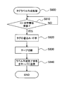
- FIG. 11 is a flowchart showing a control procedure executed by the control circuit 102 of the tag label producing apparatus 100.
- step S810 the control circuit 102 determines whether or not the tag ID and the print information are received from the control circuit 201 of the server 200 via the communication line NW (step S660 in FIG. 9, FIG. 10). (See middle step S770). This step is repeated until the tag ID and the print information are received. If received, the determination is satisfied, and the routine goes to the next Step S820.
- step S820 the control circuit 102 generates access information by the high frequency circuit 101, transmits the access information to the RFID circuit element To via the device-side antenna 106, and writes the tag ID received in step S810 to the IC circuit unit 150. I do. Further, printing is performed by the print head 105 based on the print information received in step S810.
- the control circuit 102 drives the cutter 107 to cut the tag tape 103, which has completed the above printing and information writing to the RFID circuit element To, into a predetermined length, and outputs one RFID circuit element.
- the RFID label T (the main tag label Ta and the sub tag label Tc) having To is created.
- the control circuit 102 transmits a label production completion signal indicating that the production of the RFID label T (the main tag label Ta or the sub tag label Tc) is completed to the control circuit 201 of the server 200 via the communication line NW. To do. And this flowchart is complete
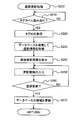
- FIG. 12 is a flowchart showing a detailed procedure of the progress update process in step S200.
- the work process of each case is in-house meeting (process 1), request form dispatch (process 2), patent office meeting (process 3), claim reception (process 4), inventor complaint check (process 5) ), Intellectual property claim check (step 6), receipt of specification draft (step 7), inventor specification check (step 8), intellectual property specification check (step 9), application (step 10), examination request (step) 11).
- the main tag label Ta is used for the steps 1 to 4
- the sub tag label Tc for the claim manuscript is used for the steps 5 to 6
- the main tag label Ta is used for the step 7, and the step 8 is used.
- Progressive updating is performed using the sub-tag label Tc for the specification document for .about.9, and the main tag label Ta for the subsequent steps 10 to 11.
- description will be made simply as the RFID label T without distinguishing the type of tag label.
- step S210 the control circuit 201 determines whether or not the tag ID has been read from the RFID label T. Specifically, the control circuit 201 transmits a control signal to the control circuit 303 of the PC 300 via the communication line NW, and the IC of the RFID tag circuit element To of the RFID label T via the high frequency circuit 402 and the antenna 401 of the reader 400. A reading signal for reading the tag ID stored in the circuit unit 150 is transmitted. Thereafter, it is determined whether the reply signal returned from the RFID circuit element To corresponding to the read signal is received via the antenna 401 and taken into the control circuit 303 via the high frequency circuit 402. This step is repeated until the tag ID is read. If the tag ID is read, the determination is satisfied, and the routine goes to the next Step S220.
- step S220 the control circuit 201 receives and acquires the tag ID acquired from the RFID label T by the control circuit 303 of the PC 300 in step S210 via the communication line NW.
- control circuit 201 searches the database 203 based on the tag ID acquired in step S220, and reads the case information and the progress related information of the patent case corresponding to the tag ID.
- the control circuit 201 transmits a control signal to the control circuit 303 of the PC 300 and updates the progress corresponding to the next work process to the display unit 301 based on the progress-related situation of the case read in step S230. Display the screen. For example, when the current progress is completed up to the patent office meeting (step 3), an update screen corresponding to the next complaint reception (step 4) is displayed.
- the control circuit 201 inputs the update information input by the IP person in charge using the operation unit 302 of the PC 300 while referring to the update screen via the communication line NW.
- the complaint receipt date entered by the person in charge of intellectual property is entered on the update screen corresponding to the complaint receipt (step 4).
- the control circuit 201 determines whether or not to update the progress. In this determination, the control circuit 201 uses an update command signal (for example, input by pressing an “update” button displayed on the screen) input by the intellectual property person using the operation unit 302 of the PC 300 to the communication line NW. This is performed depending on whether or not the message is received via. When the update command signal is not received (when updating is not performed), the determination is not satisfied and the process returns to step S250. On the other hand, when the update command signal is received (when updating is performed), the determination is satisfied, and the routine goes to the next Step S270.
- an update command signal for example, input by pressing an “update” button displayed on the screen
- step S270 the control circuit 201 registers the update information input in step S250 in the database 203 and updates the update related information. Then, this routine ends.
- the intellectual property person updates the progress using the primary tag label Ta in the steps 1 to 4, 7, 10, and 11 in which the intellectual property person manages the work, and the secondary tag label for the complaint manuscript.
- the subtag label Tc is attached to the claim manuscript so that the inventor updates the progress from step 5 to step 6 using the subtag label Tc attached to the manuscript at the end of the claim check.
- the person in charge of goods can update the progress from step 6 to step 7 using the sub tag label Tc.
- the sub tag label Tc for the specification document is issued, the sub tag label Tc attached to the specification document at the end of the specification check is used by the inventor by attaching the sub tag label Tc to the specification document.
- the progress is updated from step 8 to step 9, and the person in charge of intellectual property can update the progress from step 9 to step 10 using the sub tag label Tc.
- FIG. 13 is a flowchart showing a detailed procedure of the progress list display process in step S300.
- This progress list display can be displayed using either the primary tag label Ta or the secondary tag label Tc regardless of the progress of the project. Therefore, in the following description of FIG. 13, description will be made simply as the RFID label T without distinguishing the type of tag label.
- step S330 the control circuit 201 determines whether or not the tag ID has been read from the RFID label T. This step is repeated until the tag ID is read. If the tag ID is read, the determination is satisfied, and the routine goes to the next Step S340.
- step S340 the control circuit 201 receives and acquires the tag ID acquired from the RFID label T by the control circuit 303 of the PC 300 in step S330 via the communication line NW.
- the control circuit 201 searches the database 203 based on the tag ID acquired in the above step S340, and the case information and progress related information of the patent cases corresponding to the plurality of patent cases or tag IDs in charge by the person in charge. Read information.
- control circuit 201 transmits the case information and the progress related information read from the database 203 in the above step S350 to the control circuit 303 of the PC 300 via the communication line NW. Then, this routine ends.
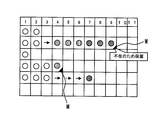
- FIG. 14 is a diagram illustrating an example of a progress list displayed on the display unit 301 of the PC 300 by the above control. Here, a case where a plurality of items are displayed in a list is shown.
- FIG. 14 in this example, there are 6 patent cases handled by the intellectual property person in charge, and the IP number, title of the invention, representative inventor, progress status, last process date, and progress graph are displayed for each case. Has been. As shown in FIG. 14, each patent case is completed by a plurality of work processes (11 processes) set along a predetermined time segment.
- a total procedure display part 310 composed of numbers from 1 to 11 representing all processes (11 processes) related to the patent project, and a symbol “ ⁇ ” for the completed processes among all the processes are attached.
- a completion procedure display section 320 is displayed.
- the progress of the case where the IP number is “2007-00002” has been completed up to the complaint check by the person in charge of the IP, and the specification manuscript from the current patent office has been completed. Waiting state.
- the process in which the arrow “ ⁇ ” is displayed in the completion procedure display unit 320 indicates that the execution of the work by the person in charge of intellectual property is omitted and skipped to the next process by a skip process described later. That is, for example, in the case of the reference number “2007-00002”, the patent office meeting (step 3) was omitted due to circumstances such as the participation of a patent office staff member in the in-house meeting (step 1). Show.
- each of the plurality of work steps in the present embodiment, each of steps 1 to 3, steps 4 to 6, steps 7 to 9, and steps 10 to 11). “)” Is displayed in different colors (the steps 10 to 11 are black circles although not shown). As a result, the person in charge of intellectual property can recognize the progress while visually distinguishing each of the plurality of work processes clearly.
- each work process has a schedule (see FIG. 19 described later), and if the progress does not proceed even after the due date, the display mode of the process is displayed. It changes (for example, the whole frame becomes red). As a result, the person in charge of intellectual property can visually recognize whether the progress is progressing according to the schedule for each of the plurality of patent cases. For example, when the operator moves the mouse to a work process that the operator wants to know, the schedule of the work process is displayed in a pop-up manner.
- the display of “ ⁇ ” indicating the completed process or “ ⁇ ” indicating the skip of the process in the completion procedure display unit 320 is not limited to this, and other display modes may be used.
- “ ⁇ ” indicating the completion process may be other symbols, characters, figures, etc.
- “ ⁇ ” indicating skip is different from other processes such as color difference, character difference, line difference, symbol addition, etc. Any display mode may be used.
- the completion procedure display unit 320 has different colors for each of the plurality of work steps.
- the present invention is not limited to this, and any display mode may be used as long as the characters are different, lines are different, symbols are added, and the like.
- the display modes are different from each other for each of the plurality of work processes.
- the display mode is not limited to this, and the display modes may be different for each item.
- FIG. 15 is a flowchart showing a detailed procedure of details of the singular mode processing in step S2000.
- step S2005 the control circuit 201 determines whether or not a case for performing the singular mode processing has been selected by the operator.
- This case selection may be performed by causing the reader 400 to read the main tag label Ta or the sub tag label Tc by the operator 400 when the above-described main tag label Ta or the sub tag label Tc has been created.
- Ta and Tc are not created, for example, the list of cases registered by the control circuit 201 is displayed on the display unit 301 of the PC 300, and the operator uses the operation unit 302 to select a specific case from the list. You may make it perform by selecting and inputting.
- the control circuit 201 repeats this step until the case selection is performed, and when it is received, the determination is satisfied, and the process proceeds to the next step S2010.
- the control circuit 201 determines whether or not the singular case mode is the “schedule change” mode.
- the unique case mode in the present embodiment is a “schedule change” mode for changing the schedule relating to the length of the time division of each work process of each patent item, and the work process (work procedure) is a previous work "Return” mode for returning to the process, "Skip” mode for skipping a predetermined work process (work procedure) and proceeding to the next work process, progress to the work process skipped in the above "Skip" mode "Skip complement” mode for returning the status, "status information addition” mode for adding the status information indicating the work status in the corresponding work process to the progress related information, and making it impossible to update the progress by the primary tag label Ta and the secondary tag label Tc "Update stop" mode to invalidate the primary tag label Ta and secondary tag label Tc, a single patent by merging multiple patent cases Is that of "projects merge” mode to manage as the progress of the matter.
- the control circuit 201 transmits a control signal to the control circuit 303 of the PC 300 via the communication line NW and causes the display unit 301 to display a unique case selection screen W1 (see FIG. 16 described later). , Based on the mode selection signal input by the operator using the operation unit 302 of the PC 300 based on the screen. If the “schedule change” mode is selected, the determination is satisfied, and the process proceeds to step S400 to perform a schedule change process for changing the schedule of each patent case (see FIG. 17 described later). Thereafter, this routine is terminated. On the other hand, if the “schedule change” mode is not selected, the determination is not satisfied and the routine goes to the next step S2020.
- step S2020 the control circuit 201 determines whether or not the singular case mode is the “return” mode. If the “return” mode is selected, the determination is satisfied, and the process proceeds to step S500, where a return process for returning the work process to the previous work process is performed (see FIG. 20 described later). Thereafter, this routine is terminated. On the other hand, if the “return” mode is not selected, the determination is not satisfied and the routine goes to the next step S2030.
- step S2030 the control circuit 201 determines whether or not the singular case mode is the “skip” mode. If the “skip” mode is selected, the determination is satisfied and the routine goes to Step S800, where a skip process is performed in which a predetermined work process is skipped and progress is advanced to the next work process (see FIG. 22 described later). . Thereafter, this routine is terminated. On the other hand, if the “skip” mode is not selected, the determination is not satisfied and the routine goes to the next step S2040.
- step S2040 the control circuit 201 determines whether or not the singular case mode is the “skip complement” mode.
- the determination is satisfied, the process proceeds to step S900, and a skip complement process for returning the progress to the work process skipped in the “skip” mode is performed (see FIG. 24 described later). Thereafter, this routine is terminated.
- the “skip complement” mode is not selected, the determination is not satisfied and the routine goes to the next step S2050.
- step S2050 the control circuit 201 determines whether or not the unique case mode is the “state information addition” mode. If the “addition of status information” mode is selected, the determination is satisfied and the routine goes to Step S1100, where a status information addition process for adding information representing the work status in the corresponding work process to the progress related information is performed (described later). FIG. 26). Thereafter, this routine is terminated. On the other hand, if the “status information addition” mode is not selected, the determination is not satisfied and the routine goes to the next step S2060.
- step S2060 the control circuit 201 determines whether or not the singular case mode is the “update stop” mode. If the “update stop” mode is selected, the determination is satisfied and the routine goes to Step S1200, where update stop processing for invalidating the progress update by the main tag label Ta and the sub tag label Tc is performed (see FIG. 29 described later). . Thereafter, this routine is terminated. On the other hand, if the “update stop” mode is not selected, the determination is not satisfied, and the routine goes to the next step S2070.
- step S2070 the control circuit 201 determines whether or not the unique case mode is the “matter merge” mode. If the “matter merger” mode is selected, the determination is satisfied and the process moves to step S1300, where a plurality of patent cases are merged to perform a case merge process for managing the progress of a single patent case. (See FIG. 31 described later). Thereafter, this routine is terminated. On the other hand, if the “matter merge” mode is not selected, the determination is not satisfied and this routine is terminated.
- the step S400 constitutes a schedule changing means for changing the schedule information regarding the length of the time division of the work procedure included in the progress related information stored and held in the database described in the claims.
- Step S500 constitutes a return means for changing the order information so that the progress returns from the corresponding work procedure to the preceding work procedure in the predetermined order, and step S800 skips the corresponding work procedure and the predetermined order.
- the skip means for changing the order information is configured so that the progress proceeds to the subsequent work procedure in step S900, and step S900 is skipped from the corresponding work procedure if necessary when the order information is changed by the skip means.
- the skip complementing means for changing the order information is configured so that the progress returns to the work procedure, and these steps S500, S800, and S900 are the order of the work procedure included in the progress related information stored and held in the database.
- the order change means is configured to change the order information related to the case so as to correspond to the singular case.
- step S1100 constitutes state information adding means for adding work state information representing the work state in the corresponding work procedure to the progress related information stored and held in the database
- step S1200 includes the second wireless tag, An invalidating means for invalidating the update so as to make progress update impossible is configured.
- step S400, step S500, step S800, step S900, step S1100, step S1200, and step S1300 together with step S200 described above constitute database update means for changing the progress related information to correspond to the singular case. To do.
- FIG. 16 is a diagram illustrating an example of a specific case selection screen W1 (single case selection means) that the control circuit 201 displays on the display unit 301 of the PC 300 in the specific mode processing.
- FIG. 17 is a flowchart showing a detailed procedure of the schedule change process in step S400.
- step S403 the control circuit 201 determines whether a return operation has been performed by the operator. In this determination, the control circuit 201 transmits a control signal to the control circuit 303 of the PC 300 via the communication line NW to display a schedule change screen (see FIG. 18 described later) on the display unit 301. Based on the operation input signal input using the operation unit 302 of the PC 300 based on the above. If a return operation has been performed, the determination is satisfied and this routine is terminated. On the other hand, if the return operation has not been performed, the process proceeds to the next step S405.
- step S405 the control circuit 201 determines whether the reader 400 has read the tag ID from the privileged tag label Ti. If the tag ID of the privileged tag label Ti has not been read, the determination is not satisfied and the routine returns to the previous step S403. On the other hand, when the tag ID of the privileged tag label Ti is read, the determination is satisfied, and the routine goes to the next Step S410.
- step S410 the control circuit 201 determines whether the patent case is an express application.
- three types of schedules for a patent matter in particular, an “urgent application” that is an urgent application, an “urgent application” that is more urgent than normal, and an “ordinary application” that is an ordinary schedule.
- the mode is set in advance (see FIGS. 18 and 19 described later).
- the control circuit 201 transmits a control signal to the control circuit 303 of the PC 300 via the communication line NW and determines the schedule change screen (described later in FIG. 18). Reference) is displayed, and based on the schedule change signal input by the operator using the operation unit 302 of the PC 300 based on the screen.
- Step S420 the schedule information included in the progress related information of the case that is the schedule change target is changed to a schedule corresponding to the express application. Thereafter, the process proceeds to step S470.
- step S410 the determination is not satisfied, and the routine goes to the next step S430.
- step S430 the control circuit 201 determines whether the patent case is an urgent application. If “rush application” is selected, the determination is satisfied, and the process proceeds to step S440, where the schedule information included in the progress related information of the case whose schedule is to be changed is changed to a schedule corresponding to the rush application. Thereafter, the process proceeds to step S470. On the other hand, if “rush application” is not selected in step S430, the determination is not satisfied and the routine goes to the next step S450.
- step S450 the control circuit 201 sets the schedule information included in the progress related information of the patent case as a schedule corresponding to the normal application (that is, the schedule is not changed).
- step S470 the control circuit 201 sets the schedule information corresponding to the express application changed in step S420, the schedule information corresponding to the rush application changed in step S440, or the normal application set in step S450.
- Schedule information is registered in the database 203. Then, this routine ends.
- the schedule of “normal application” is automatically set when “express application” and “rush application” are not selected, but it is determined whether or not “normal application” is selected by the operator.
- the schedule of “normal application” may be used.
- the user can select from three types of schedule modes. However, more types of schedule modes are prepared so that more detailed schedule changes are possible.
- the operator may input a predetermined time limit (for example, application time limit), and the schedule mode may be automatically selected (or set) according to the time limit.
- the privilege tag label Ti is read in order to confirm the change schedule (update the database 203).
- the present invention is not limited to this, and the operator operates a decision button or the like displayed on the selection screen.
- the change schedule may be fixed by (the same applies below).
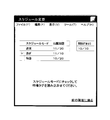
- FIG. 18 is a diagram illustrating an example of a schedule selection screen displayed on the display unit 301 of the PC 300 by the control circuit 201 in the schedule change process.
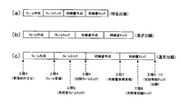
- FIG. 19 is a diagram showing an example of the schedule contents of the three types of schedule modes, “express application”, “rush application”, and “normal application”.
- “Claim creation” is the time division from the above-mentioned patent office meeting (step 3) to the claim reception (step 4), and “claim check” is known from the claim reception (step 4). This represents the time division until the goods claim check (process 6).
- “specification creation” is a time segment from the end of the IP claim check (step 6) to the receipt of the specification original (step 7), and “specification check” is the specification original receipt (step 7).
- To IP specification check (step 9) is completed, and the time segment from application (step 10) to application is shown.
- the schedule mode of “express application” and “rush application” the time division defined for each work process is shortened as compared with the case of “normal application”, and as a result, the overall schedule is reduced. It has been shortened.
- the schedule can be changed during the progress after the progress has progressed. It is. For example, if progress is made in the schedule for regular application until IP claim check (step 6), but then a sudden announcement is made and the application needs to be rushed, then the privilege tag label
- the schedule change By entering the singular mode processing using Ti and performing the above-described schedule change, it is possible to change to the schedule of the urgent application or the express application for the subsequent work procedure.
- FIG. 20 is a flowchart showing a detailed procedure of the return processing in step S500.
- step S501 the control circuit 201 determines whether a return operation has been performed by the operator. In this determination, the control circuit 201 transmits a control signal to the control circuit 303 of the PC 300 via the communication line NW to cause the display unit 301 to display a return screen (see FIG. 21 described later). Based on the operation input signal input using the operation unit 302 of the PC 300. If a return operation has been performed, the determination is satisfied and this routine is terminated. On the other hand, if the return operation has not been performed, the process proceeds to the next step S503.
- step S503 the control circuit 201 determines whether the reader 400 has read the tag ID from the privileged tag label Ti. If the tag ID of the privileged tag label Ti has not been read, the determination is not satisfied and the routine returns to the previous step S501. On the other hand, when the tag ID of the privilege tag label Ti is read, the determination is satisfied, and the routine goes to the next Step S505.
- step S505 the control circuit 201 determines whether or not to return the work process to the in-house meeting (process 1). In this determination, the control circuit 201 transmits a control signal to the control circuit 303 of the PC 300 via the communication line NW to cause the display unit 301 to display a return screen (see FIG. 21 described later). Based on the selection input signal representing the work process of the return destination selected and input using the operation unit 302 of the PC 300. If “in-house meeting” is selected, the determination is satisfied and the routine goes to Step S510, where the control circuit 201 uses the order information related to the order of the work processes included in the progress related information of the target case as the corresponding work process. Changes are made so that progress returns from in-progress work processes to in-house meetings (process 1). Thereafter, the process proceeds to step S515. On the other hand, if “in-house meeting” is not selected in step S505, the determination is not satisfied and the routine goes to the next step S515.
- step S515 the control circuit 201 determines whether or not to return the work process to the request form dispatch (process 2). If “Send Request” is selected, the determination is satisfied and the routine goes to Step S520, where the control circuit 201 uses the sequence information related to the sequence of the work processes included in the progress related information of the target case as the corresponding work. Change is made so that the progress returns from the process (work process in progress) to the dispatch of the request form (process 2). Thereafter, the process proceeds to step S525. On the other hand, if “Send request” is not selected in step S515, the determination is not satisfied and the routine goes to the next step S525.
- step S525 the control circuit 201 determines whether or not to return the work process to the patent office meeting (process 3).
- the determination is satisfied and the process proceeds to step S530, and the control circuit 201 corresponds to the order information regarding the order of the work processes included in the progress related information of the target case. Change is made so that the progress returns from the work process (work process in progress) to the patent office meeting (process 3). Thereafter, the process proceeds to step S535.
- step S525 On the other hand, if “patent office meeting” is not selected in step S525, the determination is not satisfied, and the routine goes to the next step S535.
- step S535 the control circuit 201 determines whether or not to return the work process to claim reception (process 4). If “claim receipt” is selected, the determination is satisfied and the routine goes to Step S540, where the control circuit 201 uses the order information regarding the order of the work steps included in the progress related information of the target case as the corresponding work step. Changes are made so that the progress returns from (in-progress work process) to claim reception (process 4). Thereafter, the process proceeds to step S545. On the other hand, if “claim receipt” is not selected in step S535, the determination is not satisfied and the routine goes to the next step S545.
- step S545 the control circuit 201 determines whether or not to return the work process to the inventor claim check (process 5). If “inventor claim check” is selected, the determination is satisfied and the process proceeds to step S550, and the control circuit 201 corresponds to the order information regarding the order of the work steps included in the progress related information of the target case. Changes are made so that the progress returns from the work process (work process in progress) to the inventor claim check (process 5). Thereafter, the process proceeds to step S555. On the other hand, if “inventor claim check” is not selected in step S545, the determination is not satisfied and the routine goes to the next step S555.
- Step S555 the control circuit 201 determines whether or not to return the work process to the intellectual property claim check (process 6). If “Intellectual Property Claim Check” is selected, the determination is satisfied and the routine goes to Step S560, where the control circuit 201 corresponds to the order information regarding the order of the work steps included in the progress related information of the target case. Change is made so that the progress returns from the work process (work process in progress) to the IP claim check (process 6). Thereafter, the process proceeds to step S565. On the other hand, if “IP complaint check” is not selected in step S555, the determination is not satisfied, and the routine goes to the next step S565.
- step S565 the control circuit 201 determines whether or not to return the work process to receipt of the specification document (process 7). If “description document receipt” is selected, the determination is satisfied and the process proceeds to step S570, and the control circuit 201 corresponds to the order information regarding the order of the work processes included in the progress related information of the target case. Changes are made so that the progress returns from the work process (work process in progress) to receipt of the specification document (process 7). Thereafter, the process proceeds to step S575. On the other hand, if “Receive specification document” is not selected in step S565, the determination is not satisfied and the routine goes to the next step S575.
- step S575 the control circuit 201 determines whether or not to return the work process to the inventor specification check (process 8).
- the determination is satisfied and the process proceeds to step S580, and the control circuit 201 corresponds to the order information related to the order of the work processes included in the progress related information of the target case.
- the work process is changed so that the progress returns to the inventor specification check (process 8).
- the process proceeds to step S585.
- the “inventor specification check” is not selected in step S575, the determination is not satisfied and the routine goes to the next step S585.
- step S585 the control circuit 201 determines whether or not to return the work process to the IP statement check (process 9).
- IP statement check the determination is satisfied and the process proceeds to step S590, and the control circuit 201 corresponds to the order information regarding the order of the work processes included in the progress related information of the target case. Change to return the progress from the work process (work process in progress) to the IP statement check (process 9). Thereafter, the process proceeds to step S595.
- step S585 the determination is not satisfied and the routine goes to the next step S595.
- step S595 the control circuit 201 is included in the progress related information of the target case changed in step S510, step S520, step S530, step S540, step S550, step S560, step S570, step S580, or step S590.
- the order information of the work processes to be performed is registered in the database 203. Then, this routine ends.
- FIG. 21 is a diagram illustrating an example of a return screen displayed on the display unit 301 of the PC 300 by the control circuit 201 in the return process.
- the above-described work steps 1 to 9 are displayed on the return screen.
- the operator uses the operation unit 302 to check a check box for a desired work process, thereby selecting a work process to be returned.
- the specification document receipt (step 7) is selected.
- the specification document is once delivered and the inventor specification check (step 8) or the intellectual property specification check (step 9).
- Progress is made, but when a revised matter arises and the revised specification manuscript is delivered again from the patent office, such progress can be made by returning the progress to the specification manuscript receipt (step 7). It is possible to manage the progress of documents according to specific cases.
- step 5 the inventor's claim check (step 5) is completed and the progress has been made to the intellectual property claim check (step 6). It is possible to manage the progress according to various unique cases, such as returning to the person complaint check (step 5). Note that when the return screen is displayed but the return processing is not performed, the operator performs a return operation using the operation unit 302 (the mouse pointer is clicked on the “return to previous screen” portion in the figure). Etc.) and the return process is canceled.
- FIG. 22 is a flowchart showing a detailed procedure of the skip process in step S800.
- step S801 the control circuit 201 determines whether a return operation has been performed by the operator. In this determination, the control circuit 201 transmits a control signal to the control circuit 303 of the PC 300 via the communication line NW to display a skip screen (see FIG. 23 described later) on the display unit 301, and the operator displays the screen on the screen. Based on the operation input signal input using the operation unit 302 of the PC 300. If a return operation has been performed, the determination is satisfied and this routine is terminated. On the other hand, if the return operation has not been performed, the process proceeds to the next step S803.
- step S803 the control circuit 201 determines whether the reader 400 has read the tag ID from the privileged tag label Ti. If the tag ID of the privileged tag label Ti has not been read, the determination is not satisfied and the routine returns to the previous step S801. On the other hand, when the tag ID of the privilege tag label Ti is read, the determination is satisfied, and the routine goes to the next Step S805.
- step S805 the control circuit 201 determines whether to skip (skip) the work process of the in-house meeting (process 1). In this determination, the control circuit 201 transmits a control signal to the control circuit 303 of the PC 300 via the communication line NW to display a skip screen (see FIG. 23 described later) on the display unit 301, and the operator displays the screen on the screen. On the basis of the selection input signal indicating the work process to be skipped, which is selected and input using the operation unit 302 of the PC 300. If “in-house meeting” is selected, the determination is satisfied and the routine goes to Step S810, where the control circuit 201 uses the order information regarding the order of the work processes included in the progress related information of the target case as the corresponding work process.
- step 1 The in-house meeting (step 1) is skipped, and the request work is sent out (step 2), which is the next work step, so that the progress proceeds. Thereafter, the process proceeds to step S815. On the other hand, if “in-house meeting” is not selected in step S805, the determination is not satisfied and the routine goes to the next step S815.
- Step S815 the control circuit 201 determines whether to skip (skip) the work process of sending the request form (process 2). If “Send Request” is selected, the determination is satisfied and the routine goes to Step S820, where the control circuit 201 uses the order information regarding the order of the work steps included in the progress related information of the target case as the corresponding work.
- the request form dispatch (process 2) which is a process, is skipped, and a change is made so that progress proceeds to the patent office meeting (process 3), which is the next work process. Thereafter, the process proceeds to step S825.
- step S815 the determination is not satisfied and the routine goes to the next step S825.
- the control circuit 201 determines whether to skip (skip) the work process of the patent office meeting (step 3). If “Patent Office Meeting” is selected, the determination is satisfied and the routine goes to Step S830, where the control circuit 201 corresponds to the order information regarding the order of the work processes included in the progress related information of the target case.
- the patent office meeting (process 3), which is a work process, is skipped, and a change is made so that the progress proceeds to the claim reception (process 4) which is the next work process. Thereafter, the process proceeds to step S835.
- the determination is not satisfied and the routine goes to the next step S835.
- step S835 the control circuit 201 determines whether or not to skip (skip) the work process of claim reception (process 4). If “claim receipt” is selected, the determination is satisfied and the routine goes to Step S840, where the control circuit 201 uses the order information regarding the order of the work processes included in the progress related information of the target case as the corresponding work process. Is changed so that the progress proceeds to the inventor claim check (step 5) which is the next work step. Thereafter, the process proceeds to step S845. On the other hand, if “claim receipt” is not selected in step S835, the determination is not satisfied and the routine goes to the next step S845.
- step S845 the control circuit 201 determines whether to skip (skip) the work process of the inventor claim check (process 5). If “inventor claim check” is selected, the determination is satisfied and the routine goes to Step S850, where the control circuit 201 corresponds to the order information related to the order of the work steps included in the progress related information of the target case.
- the inventor's claim check (step 5), which is a work process, is skipped, and a change is made so that progress advances to the intellectual property claim check (step 6), which is the next work process. Thereafter, the process proceeds to step S855.
- step S845 the determination is not satisfied and the routine goes to the next step S855.
- step S855 the control circuit 201 determines whether to skip (skip) the work process of the intellectual property claim check (process 6). If “IP complaint check” is selected, the determination is satisfied and the routine goes to Step S860, where the control circuit 201 responds to the order information related to the order of the work processes included in the progress related information of the target case.
- the intellectual property claim check (step 6), which is a work process, is skipped, and a change is made so that the progress proceeds to the specification original receipt (step 7) which is the next work process. Thereafter, the process proceeds to step S865.
- step S855 the determination is not satisfied and the routine goes to the next step S865.
- step S865 the control circuit 201 determines whether or not to skip (skip) the work process of receipt of the specification document (process 7). If “description document receipt” is selected, the determination is satisfied and the routine goes to Step S870, where the control circuit 201 corresponds to the sequence information related to the order of the work processes included in the progress related information of the target case.
- the specification document receipt (step 7), which is a work process, is skipped and the inventor specification check (step 8), which is the next work process, is changed so as to progress. Thereafter, the process proceeds to step S876.
- step S865 the determination is not satisfied and the routine goes to the next step S875.
- step S875 the control circuit 201 determines whether or not to skip the work process of the inventor specification check (process 8).
- the determination is satisfied and the process proceeds to step S880, and the control circuit 201 corresponds to the order information related to the order of the work processes included in the progress related information of the target case.
- the inventor specification check (step 8), which is the work process to be performed, is skipped, and the progress is advanced to the IP specification check (step 9), which is the next work process. Thereafter, the process proceeds to step S885.
- step S875 the determination is not satisfied and the routine goes to the next step S885.
- step S885 the control circuit 201 determines whether or not to skip (skip) the work procedure of the IP statement check (step 9).
- IP statement check the determination is satisfied and the process proceeds to step S890, and the control circuit 201 handles the order information regarding the order of the work processes included in the progress related information of the target case.
- the IP specification check step 9
- step 10 the application is changed to progress to the application (process 10), which is the next work process. Thereafter, the process proceeds to step S895.
- step S885 the determination is not satisfied and the routine goes to the next step S895.
- step S895 the control circuit 201 is included in the progress related information of the target case changed in step S810, step S820, step S830, step S840, step S850, step S860, step S870, step S880, or step S890.
- the order information of the work processes to be performed is registered in the database 203. Then, this routine ends.
- step S840 step S850
- step S905 step S910
- FIG. 23 is a diagram illustrating an example of a skip screen displayed on the display unit 301 of the PC 300 by the control circuit 201 in the skip process.
- the above-described work steps 1 to 9 are displayed on the skip screen.
- the operator selects a work process to be skipped by checking a check box of a desired work process using the operation unit 302.
- the three work steps of claim receipt (step 4), inventor claim check (step 5), and intellectual property claim check (step 6) are selected.
- the person in charge of the claim check does not exist for a long time, skip the above three work steps when the claim check process is skipped and the claim check is performed at the time of checking the specification document. Therefore, it is possible to manage the progress of the document according to such a specific case.
- the skip screen is displayed but skip processing is not performed, the operator performs a return operation using the operation unit 302 (the mouse pointer is clicked with the “return to the previous screen” portion in the figure). Etc.), the skip processing is canceled.
- FIG. 24 is a flowchart showing a detailed procedure of the skip complement process in step S900.
- step S901 the control circuit 201 determines whether a return operation has been performed by the operator. In this determination, the control circuit 201 transmits a control signal to the control circuit 303 of the PC 300 via the communication line NW to display a skip complement screen (see FIG. 25 described later) on the display unit 301, and the operator selects the screen. Based on the operation input signal input using the operation unit 302 of the PC 300 based on the above. If a return operation has been performed, the determination is satisfied and this routine is terminated. On the other hand, if the return operation has not been performed, the process proceeds to the next step S903.
- step S903 the control circuit 201 determines whether or not the reader 400 has read the tag ID from the privileged tag label Ti. If the tag ID of the privileged tag label Ti has not been read, the determination is not satisfied and the routine returns to the previous step S901. On the other hand, when the tag ID of the privileged tag label Ti is read, the determination is satisfied, and the routine goes to the next Step S905.
- step S905 when the in-house meeting (step 1) work process is skipped in the skip process, the control circuit 201 determines whether or not to skip the process. In this determination, the control circuit 201 transmits a control signal to the control circuit 303 of the PC 300 via the communication line NW to display a skip complement screen (see FIG. 25 described later) on the display unit 301, and the operator selects the screen. Based on the selection input signal indicating the work process to be skipped complemented and input using the operation unit 302 of the PC 300. If “in-house meeting” is selected, the determination is satisfied and the routine goes to Step S910, where the control circuit 201 uses the order information regarding the order of the work processes included in the progress related information of the target case as the corresponding work process.
- step S915. Changes are made so that progress returns from in-progress work processes to in-house meetings (process 1). Thereafter, the process proceeds to step S915. On the other hand, if “in-house meeting” is not selected in step S905, the determination is not satisfied and the routine goes to the next step S915.
- step S915 the control circuit 201 determines whether or not the process is skip-complemented when the work process of sending the request form (process 2) is skipped in the skip process. If “Send Request” is selected, the determination is satisfied and the routine goes to Step S920, where the control circuit 201 uses the order information related to the order of the work steps included in the progress related information of the target case as the corresponding work. Change is made so that the progress returns from the process (work process in progress) to the dispatch of the request form (process 2). Thereafter, the process proceeds to step S925. On the other hand, if “Send request” is not selected in step S915, the determination is not satisfied and the routine goes to the next step S925.
- step S925 when the work process of the patent office meeting (step 3) is skipped in the skip process, the control circuit 201 determines whether or not to skip the step.
- the determination is satisfied and the process proceeds to step S930, and the control circuit 201 corresponds to the order information regarding the order of the work processes included in the progress related information of the target case. Change is made so that the progress returns from the work process (work process in progress) to the patent office meeting (process 3). Thereafter, the process proceeds to step S935.
- step S925 On the other hand, if “patent office meeting” is not selected in step S925, the determination is not satisfied and the routine goes to the next step S935.
- step S935 the control circuit 201 determines whether or not the process is skip-complemented when the work process of the claim reception (process 4) is skipped in the skip process. If “claim receipt” is selected, the determination is satisfied and the routine goes to Step S940, where the control circuit 201 uses the order information regarding the order of the work processes included in the progress related information of the target case as the corresponding work process. Changes are made so that the progress returns from (in-progress work process) to claim reception (process 4). Thereafter, the process proceeds to step S945. On the other hand, if “claim receipt” is not selected in step S935, the determination is not satisfied and the routine goes to the next step S945.
- Step S945 when the work process of the inventor claim check (step 5) is skipped in the skip processing, the control circuit 201 determines whether or not to skip the step. If “inventor claim check” is selected, the determination is satisfied and the routine goes to Step S950, where the control circuit 201 corresponds to the order information related to the order of the work steps included in the progress related information of the target case. Changes are made so that the progress returns from the work process (work process in progress) to the inventor claim check (process 5). Thereafter, the process proceeds to step S955. On the other hand, if “inventor claim check” is not selected in step S945, the determination is not satisfied and the routine goes to the next step S955.
- step S955 when the work process of the intellectual property claim check (step 6) is skipped in the skip processing, the control circuit 201 determines whether or not to skip the step. If “IP complaint check” is selected, the determination is satisfied and the routine goes to Step S960, where the control circuit 201 corresponds to the sequence information related to the order of the work processes included in the progress related information of the target case. Change is made so that the progress returns from the work process (work process in progress) to the IP claim check (process 6). Thereafter, the process proceeds to step S965. On the other hand, if “IP complaint check” is not selected in step S955, the determination is not satisfied and the routine goes to the next step S965.
- step S965 the control circuit 201 determines whether or not the process is skip-complemented when the work process of receipt of the specification document (process 7) is skipped in the skip process. If “description document receipt” is selected, the determination is satisfied and the process proceeds to step S970, and the control circuit 201 corresponds to the order information regarding the order of the work steps included in the progress related information of the target case. Changes are made so that the progress returns from the work process (work process in progress) to receipt of the specification document (process 7). Thereafter, the process proceeds to step S975. On the other hand, if “Receive specification document” is not selected in step S965, the determination is not satisfied and the routine goes to the next step S975.
- step S975 when the work process of the inventor specification check (step 8) is skipped in the skip processing, the control circuit 201 determines whether or not to skip the step.
- “inventor specification check” is selected, the determination is satisfied and the process proceeds to step S980, and the control circuit 201 handles the order information regarding the order of the work processes included in the progress related information of the target case. The work process is changed so that the progress returns to the inventor specification check (process 8). Thereafter, the process proceeds to step S985.
- the “inventor specification check” is not selected in step S975, the determination is not satisfied and the routine goes to the next step S985.
- step S985 when the IP statement check (step 9) work step is skipped in the skip processing, the control circuit 201 determines whether or not to skip the step.
- IP statement check the determination is satisfied and the process proceeds to step S990, and the control circuit 201 handles the order information regarding the order of the work processes included in the progress related information of the target case. Change to return the progress from the work process (work process in progress) to the IP statement check (process 9). Thereafter, the process proceeds to step S995.
- step S985 On the other hand, if “IP statement check” is not selected in step S985, the determination is not satisfied and the routine goes to the next step S995.
- step S995 the control circuit 201 is included in the progress related information of the target case changed in step S910, step S920, step S930, step S940, step S950, step S960, step S970, step S980, or step S990.
- the order information of the work processes to be performed is registered in the database 203. Then, this routine ends.
- FIG. 25 is a diagram illustrating an example of a skip complement screen that the control circuit 201 displays on the display unit 301 of the PC 300 in the skip complement process.
- the above-described work steps 1 to 9 are displayed on the skip complement screen.
- the operator selects a work process to be skipped by checking a check box of a desired work process using the operation unit 302.
- the inventor specification check (step 8) is selected. This is because the inventor specification check (step 8) is performed due to the fact that the inventor is absent for a long time at the time of the specification check. If the inventor has returned and the progress has been advanced, the inventor has returned to the inventor specification check (step 8) to complete the skip and complete the skip. It is possible to manage the progress status. If the skip complement screen is displayed but skip complement processing is not performed, the operator performs a return operation using the operation unit 302 (move the mouse pointer to the “return to previous screen” portion in the figure). Click), the skip complement process is canceled.
- FIG. 26 is a flowchart showing a detailed procedure of the state information addition process in step S1100.
- step S1101 the control circuit 201 determines whether a return operation has been performed by the operator. In this determination, the control circuit 201 transmits a control signal to the control circuit 303 of the PC 300 via the communication line NW to cause the display unit 301 to display a state addition screen (see FIG. 27 described later). Based on the operation input signal input using the operation unit 302 of the PC 300 based on the above. If a return operation has been performed, the determination is satisfied and this routine is terminated. On the other hand, if the return operation has not been performed, the process proceeds to the next step S1103.
- step S1103 the control circuit 201 determines whether the reader 400 has read the tag ID from the privileged tag label Ti. If the tag ID of the privileged tag label Ti has not been read, the determination is not satisfied and the routine returns to the previous step S1101. On the other hand, when the tag ID of the privilege tag label Ti is read, the determination is satisfied, and the routine goes to the next Step S1105.
- step S1105 the control circuit 201 determines whether or not to add state information to the in-house meeting (step 1). In this determination, the control circuit 201 transmits a control signal to the control circuit 303 of the PC 300 via the communication line NW to cause the display unit 301 to display a state addition screen (see FIG. 27 described later). Based on the selection input signal representing the work process to which the state information addition target is selected and input using the operation unit 302 of the PC 300. If “in-house meeting” is selected, the determination is satisfied and the process proceeds to step S1110, and the control circuit 201 inputs the in-house meeting that is input by the operator on the status addition screen to the progress-related information of the target case. It changes so that the additional information showing the working state of (process 1) may be added. Thereafter, the process proceeds to step S1115. On the other hand, if “in-house meeting” is not selected in step S1105, the determination is not satisfied and the routine goes to the next step S1115.
- step S1115 the control circuit 201 determines whether or not to add status information to the request form dispatch (step 2). If “Request Shipment” is selected, the determination is satisfied and the routine goes to Step S1120, where the control circuit 201 adds the request input by the operator on the status addition screen to the progress related information of the target case. It changes so that the additional information showing the work state of document dispatch (process 2) may be added. Thereafter, the process proceeds to step S1125. On the other hand, if “Send request” is not selected in step S1115, the determination is not satisfied and the routine goes to the next step S1125.
- step S1125 the control circuit 201 determines whether or not to add status information to the patent office meeting (step 3). If “Patent Office Meeting” is selected, the determination is satisfied and the routine goes to Step S1130, where the control circuit 201 inputs the progress-related information of the target case by the operator on the status addition screen. It changes so that the additional information showing the working state of a patent office meeting (process 3) may be added. Thereafter, the process proceeds to step S1135. On the other hand, if “patent office meeting” is not selected in step S1125, the determination is not satisfied, and the routine goes to the next step S1135.
- step S1135 the control circuit 201 determines whether or not to add state information to the claim reception (step 4). If “claim received” is selected, the determination is satisfied, and the process proceeds to step S1140, where the control circuit 201 adds the patent complaint that has been input by the operator on the status addition screen to the progress related information of the target case. It changes so that the additional information showing the work state of reception (process 4) may be added. Thereafter, the process proceeds to step S1145. On the other hand, if “claim receipt” is not selected in step S1135, the determination is not satisfied, and the routine goes to the next step S1145.
- step S1145 the control circuit 201 determines whether or not to add state information to the inventor claim check (step 5). If “inventor claim check” is selected, the determination is satisfied and the routine goes to Step S1150, where the control circuit 201 inputs the progress related information of the target case into the status addition screen by the operator. It changes so that the additional information showing the work state of an inventor claim check (process 5) may be added. Thereafter, the process proceeds to step S1155. On the other hand, if “inventor claim check” is not selected in step S1145, the determination is not satisfied and the routine goes to the next step S1155.
- step S1155 the control circuit 201 determines whether or not to add state information to the intellectual property claim check (step 6). If “Intellectual Property Complaint Check” is selected, the determination is satisfied and the routine goes to Step S1160, where the control circuit 201 inputs the progress related information of the target case into the status addition screen by the operator. It changes so that the additional information showing the work state of an intellectual property claim check (process 6) may be added. Thereafter, the process proceeds to step S1165. On the other hand, if “IP complaint check” is not selected in step S1155, the determination is not satisfied and the routine goes to the next step S1165.
- step S1165 the control circuit 201 determines whether or not to add status information to the specification document receipt (step 7). If “description document receipt” is selected, the determination is satisfied and the routine goes to Step S1170, where the control circuit 201 inputs the progress-related information of the target case by the operator on the status addition screen. Changes are made to add additional information indicating the work status of receipt of the specification document (step 7). Thereafter, the process proceeds to step S1175. On the other hand, if “description document receipt” is not selected in step S1165, the determination is not satisfied and the routine goes to the next step S1175.
- step S1175 the control circuit 201 determines whether or not to add state information to the inventor specification check (step 8).
- the determination is satisfied and the process proceeds to step S1180, and the control circuit 201 inputs the progress related information of the target case on the state addition screen by the operator.
- the additional information indicating the work state of the inventor specification check (step 8) is changed. Thereafter, the process proceeds to step S1185.
- step S1175 the determination is not satisfied and the routine goes to the next step S1185.
- step S1185 the control circuit 201 determines whether or not to add state information to the intellectual property specification check (step 9). If “IP statement check” is selected, the determination is satisfied, and the process proceeds to step S1190, where the control circuit 201 inputs the progress related information of the target case by the operator on the state addition screen. Then, it is changed so as to add additional information indicating the work state of the IP statement check (step 9). Thereafter, the process proceeds to step S1195. On the other hand, if “IP statement check” is not selected in step S1185, the determination is not satisfied and the routine goes to the next step S1195.
- step S1195 the control circuit 201 executes each work added to the progress related information of the target case in step S1110, step S1120, step S1130, step S1140, step S1150, step S1160, step S1170, step S1180, or step S1190.
- Process state information is registered in the database 203. Then, this routine ends.
- FIG. 27 is a diagram illustrating an example of a state addition screen displayed on the display unit 301 of the PC 300 by the control circuit 201 in the state information addition process.
- a work state input column for inputting a work state and the above-described work steps 1 to 9 are displayed.
- the operator uses the operation unit 302 to check a check box of a desired work process, thereby selecting a work process to be added with state information and inputting a work state in the work state input field.
- “Pending due to absence of IP person in charge” is entered in the work status input field, and IP statement check (step 9) is selected. This is known at the time of statement check. If the specification cannot be checked due to the absence of the person in charge of the goods, the status of the IP statement check (step 9) can be put on hold to clarify the reason and hold the progress.
- FIG. 28 is a diagram illustrating an example of display in the progress list display when the state information is added by the state information addition process.
- the identification mark M is displayed in the work process to which the status information is added.
- the state information of the process is displayed in a pop-up manner.
- the operator may be prompted to reconfirm the working state by changing the display mode of the corresponding work process or displaying a separate warning.
- FIG. 29 is a flowchart showing a detailed procedure of the update stop process in step S1200.
- step S1210 the control circuit 201 determines whether the reader 400 has read the tag ID from the privileged tag label Ti. This step is repeated until the tag ID of the privileged tag label Ti is read. If the tag ID of the privileged tag label Ti is read, the determination is satisfied, and the routine goes to the next Step S1220.
- step S1220 the control circuit 201 invalidates the main tag label Ta and the sub tag label Tc so that the progress update by the main tag label Ta and the sub tag label Tc is impossible.
- the association information stored in the database 203 between the tag IDs of the main tag label Ta and the sub tag label Tc corresponding to the case that is the update stop target, and the case information and the progress related information of the case Change and register so that there is no more.
- the control circuit 201 stores the case information and the progress related information of the corresponding case based on the acquired tag ID. Since it becomes impossible to read from, update is impossible. Then, this routine ends.
- FIG. 30 is a diagram illustrating an example of an update stop screen displayed on the display unit 301 of the PC 300 by the control circuit 201 in the update stop process.
- the update stop screen is displayed to prompt the operator to read the privilege tag label Ti.
- the operator performs a return operation using the operation unit 302 (move the mouse pointer to “return to the previous screen” in the figure).
- the update stop process is canceled when clicked.
- the update stop process is performed, for example, in the case of an ongoing project, when a very close prior art is found by prior art search, etc. and the application is abandoned. It is possible to manage the progress of documents according to such anomalous cases.
- FIG. 31 is a flowchart showing the detailed procedure of the case merging process in step S1300.
- step S1310 the control circuit 201 transmits a control signal to the control circuit 303 of the PC 300 via the communication line NW to display a case merge screen (see FIG. 32 described later) on the display unit 301.
- the case information for example, IP number
- the case to be merged which is input using the operation unit 302 of the PC 300, is input via the communication line NW.
- the control circuit 201 determines whether the reader 400 has read the tag ID from the privileged tag label Ti. If the tag ID of the privileged tag label Ti is not read, the determination is not satisfied and the process returns to step S1310. On the other hand, if the tag ID of the privileged tag label Ti is read, the determination is satisfied, and the routine goes to the next Step S1330.
- step S1330 the control circuit 201 handles the case that is the target of the singular mode process (the case selected in the above-described step S2005, hereinafter referred to as “current case” as appropriate) and the case input in step S1310. (Hereinafter referred to as “consolidated project” where appropriate) and the progress status is managed as a single project, a representative wireless tag for progress management is determined.
- the main tag label Ta and the sub tag label Tc corresponding to both the current case and the merged case are determined as representative wireless tags (in other words, the main tag label Ta and the sub tag label corresponding to the current case and the merged case, respectively). Tc is unified as corresponding to the current case).
- the database so that the tag IDs of the primary tag label Ta and the secondary tag label Tc respectively corresponding to the two cases of the current case and the merged case are associated with the case information and the progress related information of the current case that is the representative case.
- the association information stored in 203 is changed.
- the changed information is registered in the database 203, and this routine is terminated.
- the control circuit 201 Updates the case information and the progress related information of the case corresponding only to the current case. As a result, it is possible to manage the progress status as a single case with the merged case merged with the current case.
- step S1330 is a representative when managing the progress of document processing in a plurality of events described in the claims as a single event representing a plurality of events.
- the representative tag determining means for determining the representative wireless tag corresponding to the event is configured.
- FIG. 32 is a diagram illustrating an example of a case merging screen that the control circuit 201 displays on the display unit 301 of the PC 300 in the case merging process.
- a case information input column for inputting case information (intellectual property number in this example) is displayed.
- the operator selects item to be merged with the current item by inputting item information of a desired item using the operation unit 302.
- the case merge screen is displayed but the case merge processing is not performed, the operator performs a return operation using the operation unit 302 (move the mouse pointer to the “return to previous screen” portion in the figure). Clicking etc.) cancels the merge process.
- the above-mentioned case consolidation processing is performed, for example, when filing an application claiming priority under the Paris Convention or domestic priority based on a plurality of filings.
- merging it is possible to manage the progress of documents according to such anomalous cases.
- progress-related information related to the progress or schedule of document processing of at least one patent application case is stored and held in the database 203.
- the progress related information corresponding to each case in the database 203 can be centrally managed using the progress related information. Can do.
- the reader 400 acquires information from the privileged tag label Ti via wireless communication, thereby controlling the control circuit 201 of the server 200.
- the progress related information stored and held in the database 203 is changed to correspond to the unique case.
- the progress status of the event can be managed using the changed progress-related information while corresponding to the specific case.
- the tag ID of the privileged tag label Ti is acquired by the reader 400
- at least one unique case is selected from a plurality of specific cases preset in the unique case selection screen W1
- the control circuit 201 of the server 200 changes the progress related information stored and held in the database 203 according to the content of the selected unique case.
- progress related information can be changed according to the desired specific case selected by the operator from various specific cases, so the progress of document processing in the event can be managed while corresponding to the desired specific case can do.
- the control circuit 201 of the server 200 performs the work included in the progress related information stored and held in the database 203 in the schedule change process in step S400. Change the schedule information regarding the length of the time division of the process. As a result, even if it is necessary to change the originally scheduled schedule before or during the progress of the matter, the progress of document processing in the event can be managed while corresponding to the changed schedule. .
- the control circuit 201 of the server 200 when the tag ID is acquired from the privileged tag label Ti by the reader 400, the control circuit 201 of the server 200 performs the return processing, skip processing, or skip complement processing in step S500, step S800, or step S900.
- the order information regarding the order of the work procedures included in the progress related information stored and held in the database 203 is changed so as to correspond to the unique case.
- the progress of document processing in the event can be managed while changing the order of the work procedures correspondingly.
- the control circuit 201 of the server 200 progresses from the corresponding work process to the previous work process in a predetermined order in the return processing in step S500. Change the order information so that.
- the progress of document processing in the event can be managed while returning the work process correspondingly.
- the control circuit 201 of the server 200 skips the corresponding work process in the skip process of step S800, and the subsequent work process in a predetermined order.
- the order information is changed so that the progress proceeds.
- the order information is changed so that the control circuit 201 of the server 200 skips the corresponding work process in the skip process of step S800 and progresses to the next work process
- the order information is changed so that the progress returns to the work process skipped from the corresponding work process in the skip complementing process in step S900.
- the work process was skipped during the progress of the project and proceeded to the next work process, but when it was necessary to execute the skipped work process, the progress was returned to the work process skipped correspondingly.
- the control circuit 201 of the server 200 obtains the work state information indicating the work state in the corresponding work process in the state information addition process in step S1100. , Added to the progress related information stored and held in the database 203. This makes it possible to manage the progress of document processing in a case while the work procedure is put on hold in response to a need to suspend the work process due to some reason during the progress of the case. .
- the control circuit 201 of the server 200 performs step S200.
- the progress update process the progress related information stored and held in the database 203 is changed so that the progress proceeds to a predetermined work process.
- the progress related information corresponding to each case in the database 203 is updated according to the actual progress of each case, so the progress of document processing in each case is centrally managed using the progress related information. can do.
- the control circuit 201 of the server 200 invalidates the primary tag label Ta and the secondary tag label Tc in the update stop process in step S1200
- the control circuit 201 of the server 200 uses the reader 400 to execute the primary tag label Ta. Even if the tag ID of the sub tag label Tc is acquired, the progress related information stored and held in the database 203 is not updated. Thereby, when it becomes necessary to stop the progress of the case for some reason during the progress of the case, it is possible to stop the progress correspondingly and prevent the progress from progressing thereafter.
- control circuit 201 of the server 200 determines a representative wireless tag corresponding to a single case that represents a plurality of cases in step S1330, whereby the progress of document processing in the plurality of cases. Can be centrally managed as the progress of a single event.
- the control circuit 201 of the server 200 sets the main tag label Ta and the sub tag label Tc corresponding to a plurality of cases in step S1330 to the main tag label Ta and the sub tag corresponding to a single representative case. It unifies as a tag label Tc. Thereby, the control circuit 201 of the server 200 reads the tag ID of the primary tag label Ta or the secondary tag label Tc corresponding to any of the primary tag label Ta and the secondary tag label Tc of a plurality of unified cases by the reader 400. Even in this case, the progress related information of the corresponding single case is updated. Therefore, when it is necessary to manage the progress of a plurality of events as a single event for some reason, it is possible to manage the progress of document processing in a single event corresponding to this.
- the database 203 stores and holds progress-related information related to the progress of document processing at the time of creating a specification for a patent application project.
- the database 203 stores and holds progress-related information related to the progress of document processing at the time of creating a specification for a patent application project.
- FIG. 33 is a diagram illustrating an example of the notification screen W2 that is displayed on the display unit 301 of the PC 300 by the control circuit 201.
- the notification screen W2 (notification means) prompts the operator to select whether or not to perform skip complementation by displaying a message for confirming whether or not to perform skip complementation. .
- This screen is displayed, for example, when logging in to the patent progress management system PS. If the operator causes the privileged tag label Ti to be read by the reader 400, the process directly proceeds to the skip complement process in step S900 described above. On the other hand, when the operator causes the operator tag label other than the privileged tag label Ti, the main tag label Ta, or the sub tag label Tc to be read, the process proceeds to the normal mode process of step S1000 described above.
- the notification screen W2 notifies the operator to that effect.
- the work process was skipped during the progress of the project and proceeded to the next work process, but the operator forgets to execute the work process when it becomes necessary to execute the skipped work process. Can be prevented.
- the control circuit 201 of the server 200 determines both the current case and the merged case in step S1330 during the case merging process.
- the main tag label Ta and the sub tag label Tc corresponding to the project are determined as the representative wireless tags and the wireless tags are unified, the present invention is not limited to this. That is, for example, out of the main tag label Ta and the sub tag label Tc corresponding to the current case and the merged case, the main tag label Ta and the sub tag label Tc corresponding to one case may be represented, and the other may be invalidated.
- the control circuit 201 of the server 200 acquires the tag ID of the representative primary tag label Ta or secondary tag label Tc by the reader 400 in the progress update process of step S200
- the progress related information of the corresponding case is acquired.
- the tag ID of the invalidated main tag label Ta or subordinate tag label Tc is acquired by the reader 400, the progress related information of the corresponding item is not updated.
- the main tag label Ta and the sub tag label Tc corresponding to both the current case and the merged case are determined as the representative wireless tags, respectively.
- the present invention is not limited to this. That is, for example, a new primary tag label Ta and secondary tag label Tc corresponding to a single case after the merger are created, and the primary tag label Ta and secondary tag label Tc corresponding to both the original current case and the secondary case are invalidated, respectively. You may make it do.
- the control circuit 201 of the server 200 invalidates all the main tag labels Ta and sub tag labels Tc corresponding to each of the plurality of cases in step S1330 during the case merging process, A creation instruction signal for creating a new primary tag label Ta ′ and a secondary tag label Tc ′ (not shown) corresponding to the case is output to the tag label creation device 100.
- the tag label producing apparatus 100 the tag tape 103 is conveyed by the conveying device 109, predetermined printing is performed on the tag tape 103 by the print head 105, and the tag circuit 103 is provided with the RFID tag circuit element To.
- the RFID label T formed in a label shape is used as the RFID tag.
- the present invention is not limited to this, and information can be transmitted / received to / from the outside via wireless communication such as an IC card. If so, other tag media may be used.
- the tag ID is stored in the RFID circuit element To of each RFID label T, and the information associated with the tag ID is retrieved from the database 203, read out, and used.
- the unique case information itself (schedule change, return, skip, etc.) is stored in the RFID tag circuit element To of the privileged tag label Ti, and the event related information itself (case information etc.) is stored in the RFID circuit of the primary tag label Ta and the secondary tag label Tc. You may make it memorize
- the work process has 11 items.
- the present invention is not limited to this, and the items may be appropriately replaced or added.
- the claims and the specification manuscript are received separately from the patent office, but may be received together as a patent specification.
- the work process is up to the request for examination, but subsequent processes such as an interim procedure such as submission of an opinion or amendment and a trial procedure such as a request for appeal against decision of rejection may be added.
- the document processing progress management system is applied to the patent progress management system for managing the patent progress, and the process proceeds by checking the content of the document related to the patent application.
- the present invention can also be applied to a case where the process is advanced by painting or writing a document when the process is divided for document processing, for example, illustration creation.
- the case where the PC 300 as the progress display device is applied to a patent progress management system that manages the progress of patent cases has been described as an example, but the present invention is not limited thereto. That is, for example, processing management of various approval documents, progress management from acquisition of fixed assets to disposal (estimate, application, slip, delivery note, acceptance, disposal application, etc.), management of multiple workflows in the project, and construction Any system that manages the progress of events completed by a plurality of work procedures, such as process management in the field, can be applied to other systems.
- the wireless communication performed between the RFID tag circuit element To of the RFID label T and the antenna 401 of the reader 400 has not been particularly described.
- information transmission / reception is performed by radio wave communication using the UHF band.
- a coiled loop antenna may be used as the antenna 401 of the reader 400 and the tag-side antenna 151 on the RFID tag circuit element To side, and magnetic induction (electromagnetic induction, magnetic coupling, or other electromagnetic fields may be performed using the HF band.
- Information transmission / reception may be performed using a non-contact method performed in the same manner.
- the RFID label T is created by cutting the tag tape 103 that has been printed and accessed (written) to the RFID circuit element To by the cutter 107 is described as an example. Absent. That is, in the case where a label mount (so-called die-cut label) previously separated into a predetermined size corresponding to the label is continuously arranged on the tape fed out from the roll, even if it is not cut by the cutter 107, After the tag tape 103 is discharged from the discharge port, the RFID label label T may be created by removing only the label mount (the one with the already accessed RFID tag circuit element To and the corresponding printing) from the tape. The present invention is also applicable to such a case.
- the tag tape 103 is wound around the reel member to form the tag tape roll 104 (or the cartridge including the tag tape roll 104), and the tag tape 103 is fed out from the roll 104.
- this is not a limitation.
- a long flat paper-like or strip-like tape or sheet in which at least one RFID circuit element To is arranged (the one formed by cutting a tape wound around a roll and cutting it to an appropriate length) are stacked in a predetermined storage unit (for example, stacked in a tray shape) to form a cartridge, and the cartridge is attached to the cartridge holder on the tag label producing apparatus side, and is transported and transported from the storage unit.
- the RFID label T may be created by printing and writing.
- a structure in which the roll is directly detachably attached to the tag label producing apparatus side, or a long flat paper-like or strip-like tape or sheet is transferred one by one from the outside of the tag label producing apparatus by a predetermined feeder mechanism. It is also possible to supply the inside of the apparatus, and it is not limited to a tag label producing apparatus main body side such as a tag tape roll 104 (or a cartridge including the tag tape roll 104). It is also conceivable to provide the tag tape roll 104 as a mold or an integrated mold. In this case, the same effect is obtained.
- a method for directly printing on a tag tape (so-called non-laminate type) is used, but the present invention is not limited to this, and a cover film (printed object) different from the tag tape 103 provided with the RFID circuit element To is used.
- the present invention may be applied to a method (so-called laminate type) in which printing is performed on a medium) and these are bonded together.
- FIG. 11 is a diagram illustrating an example of a notification screen that is displayed on a display unit of a PC by a control circuit in a modification in which there is a skipped process.
- Tag label production apparatus 101 High frequency circuit (tag access means) 103 Tag tape (tag medium) 105 Print head (printing means) 106 Antenna (tag access means) 109 Conveying device (conveying means) 150 IC Circuit Unit 151 Tag Side Antenna 203 Database 400 Reader PS Patent Progress Management System (Document Processing Progress Management System) Ta Main tag label (second radio tag) Tc Secondary tag label (second wireless tag) Ti Privilege tag label (1st wireless tag) To RFID circuit element Ta 'Main tag label (third RFID tag) Tc 'Secondary tag label (third radio tag) W1 Singular case selection screen (Singular case selection means) W2 notification screen (notification means)
Landscapes
- Physics & Mathematics (AREA)
- General Physics & Mathematics (AREA)
- Engineering & Computer Science (AREA)
- Theoretical Computer Science (AREA)
- Management, Administration, Business Operations System, And Electronic Commerce (AREA)
Abstract
【課題】複数の作業手順の進捗状況を一元管理すると共に、進捗に関する特異事例が生じた場合にも、特異事例に応じて進捗状況を管理することができる書類処理進捗管理システムを提供する。 【解決手段】予め、所定順序の時間区分に沿って設定された複数の作業工程により完遂される少なくとも1つの特許出願案件の書類処理の進捗又は進捗予定に関する進捗関連情報を格納保持するデータベース203と、案件の進捗に関わる特異事例に対応するタグIDを記憶する特権タグラベルTiと、特権タグラベルTiに記憶されたタグIDを無線通信を介し取得するリーダ400と、リーダ400で特権タグラベルTiのタグIDを取得した場合に、データベース203に格納保持された進捗関連情報を、特異事例に対応するように変更するサーバ200の制御回路201とを有する。
Description
本発明は、情報を記憶するIC回路部と情報を送受信するタグ側アンテナとを備えた無線タグ回路素子を有する無線タグラベルを作成するためのタグラベル作成装置を備えた書類処理進捗管理システムに関する。
近年、所定の無線タグ情報を記憶するIC回路部とこのIC回路部に接続されて情報の送受信を行うアンテナとを備えた無線タグ回路素子を有する小型の無線タグとリーダ(読み取り装置)/ライタ(書き込み装置)との間で非接触で情報の読み取り/書き込みを行うRFID(Radio Frequency Identification)システムが提唱されており、様々な分野において実用化されつつある。
上記RFIDシステムの従来技術として、例えば特許文献1に記載のものがある。この従来技術では、書類に無線タグラベル(RFIDタグ)を取り付けると共に、その無線タグラベルが有する無線タグ回路素子のタグ識別情報(タグ識別子)と書類情報とを関連付けてデータベースに格納する。さらに、ワークフローの領域近辺に複数のリーダ(センサ)が設けられており、これら各リーダの場所も事前にデータベースに登録されている。これにより、書類に取り付けられた無線タグラベルのタグ識別情報がリーダで読み取られると、そのタグ識別情報と書類情報、及び場所が対応付けられ、書類の場所が把握できるようになっている。このようにして、書類の物理的な動きを追跡可能としている。
一般に業務の進行においては、複数の作業手順が並行して進捗する。したがって、業務を効果的に管理するには、複数の作業手順の進捗状況を一元管理する必要がある。このとき、上記従来技術のシステムでは、業務の進行に伴って作成される書類の物理的な動きを追跡することは可能であるが、その書類の動きにより作業手順が進捗しても、その進捗状況を把握することができなかった。
さらには、作業手順の進捗において、スケジュール変更や予定された作業手順の変更(手順の追加・削除・順番変更等)などの進捗に関する特異事例が生じた場合にも、これに対応して進捗状況を管理することができなかった。
本発明の目的は、複数の作業手順の進捗状況を一元管理すると共に、進捗に関する特異事例が生じた場合にも、特異事例に応じて進捗状況を管理することができる書類処理進捗管理システムを提供することにある。
上記目的を達成するために、第1の発明の書類処理進捗管理システムは、予め、所定順序の時間区分に沿って設定された複数の作業手順により完遂される少なくとも1つの事象の書類処理の進捗又は進捗予定に関する進捗関連情報を格納保持するデータベースと、前記事象の進捗に関わる特異事例に対応する特異事例情報を記憶する第1無線タグと、前記第1無線タグに記憶された前記特異事例情報を無線通信を介し取得するリーダと、前記リーダで前記第1無線タグの特異事例情報を取得した場合に、前記データベースに格納保持された前記進捗関連情報を、前記特異事例に対応するように変更するデータベース更新手段とを有することを特徴とする。
本願第1発明の書類処理進捗管理システムでは、少なくとも1つの事象の書類処理の進捗又は進捗予定に関する進捗関連情報が、データベースに格納保持されている。このデータベース中の各事象に対応する進捗関連情報を、各事象の実際の進捗状況に合わせて更新することで、当該進捗関連情報を用いて各事象における書類処理の進捗状況を一元管理することが可能となる。
一方、スケジュール変更や作業手順の変更等の事象の進捗に関わる特異事例が発生した場合には、リーダで第1無線タグから無線通信を介して特異事例情報を取得することで、データベース更新手段が、データベースに格納保持された進捗関連情報を特異事例に対応するように変更する。これにより、変更された進捗関連情報を用いて、特異事例に対応しつつ事象の進捗状況を管理することができる。
このように、本願第1発明によれば、少なくとも1つの事象における書類処理の進捗状況を一元管理することができ、且つ、進捗に関する特異事例が生じた場合にも、特異事例に対応しつつ進捗状況を管理することができる。
第2発明の書類処理進捗管理システムは、上記第1発明において、前記リーダで前記第1無線タグの特異事例情報を取得した場合に、予め設定された複数の特異事例の中から少なくとも1つの特異事例を選択可能な特異事例選択手段をさらに有し、前記データベース更新手段は、前記特異事例選択手段で選択された前記特異事例の内容に応じ、前記データベースに格納保持された前記進捗関連情報を変更することを特徴とする。
本願第2発明においては、リーダで第1無線タグの特異事例情報を取得した場合に、特異事例選択手段が予め設定された複数の特異事例の中から少なくとも1つの特異事例を選択し、この選択された特異事例の内容に応じ、データベース更新手段がデータベースに格納保持された進捗関連情報を変更する。これにより、種々の特異事例の中から操作者が選択した所望の特異事例に応じて進捗関連情報を変更することができるので、所望の特異事例に対応しつつ事象における書類処理の進捗状況を管理することができる。
第3発明の書類処理進捗管理システムは、上記第2発明において、前記データベース更新手段は、前記リーダで前記第1無線タグの特異事例情報を取得した場合に、前記特異事例選択手段の選択結果に基づき、前記データベースに格納保持された前記進捗関連情報に含まれる前記作業手順の前記時間区分の長さに関するスケジュール情報を変更するスケジュール変更手段を有することを特徴とする。
本願第3発明においては、リーダにより第1無線タグから特異事例情報を取得すると、スケジュール変更手段が、データベースに格納保持された進捗関連情報に含まれる作業手順の時間区分の長さに関するスケジュール情報を変更する。これにより、事象の進捗進行前又は進捗途中で当初予定したスケジュールを変更する必要が生じた場合であっても、当該変更したスケジュールに対応しつつ事象における書類処理の進捗状況を管理することができる。
第4発明の書類処理進捗管理システムは、上記第2又は第3発明において、前記データベース更新手段は、前記リーダで前記第1無線タグの特異事例情報を取得した場合に、前記特異事例選択手段の選択結果に基づき、前記データベースに格納保持された前記進捗関連情報に含まれる前記作業手順の順序に関する順序情報を、前記特異事例に対応するように変更する順序変更手段を有することを特徴とする。
本願第4発明においては、リーダにより第1無線タグから特異事例情報を取得すると、順序変更手段が、データベースに格納保持された進捗関連情報に含まれる作業手順の順序に関する順序情報を、特異事例に対応するように変更する。これにより、事象の進捗途中で作業手順の順序を変更する必要が生じた場合に、これに対応して作業手順の順序を変更しつつ、事象における書類処理の進捗状況を管理することができる。
第5発明の書類処理進捗管理システムは、上記第4発明において、前記順序変更手段は、対応する作業手順から前記所定順序におけるその前段の作業手順に進捗が戻るように、前記順序情報を変更する差し戻し手段を有することを特徴とする。
本願第5発明においては、リーダにより第1無線タグから特異事例情報を取得すると、差し戻し手段が、対応する作業手順から所定順序におけるその前段の作業手順に進捗が戻るように、順序情報を変更する。これにより、事象の進捗途中で作業手順を差し戻す必要が生じた場合に、これに対応して作業手順を差し戻しつつ、事象における書類処理の進捗状況を管理することができる。
第6発明の書類処理進捗管理システムは、上記第4又は第5発明において、前記順序変更手段は、対応する作業手順を飛ばして前記所定順序におけるその後段の作業手順に進捗が進むように、前記順序情報を変更するスキップ手段を有することを特徴とする。
本願第6発明においては、リーダにより第1無線タグから特異事例情報を取得すると、スキップ手段が、対応する作業手順を飛ばして所定順序におけるその後段の作業手順に進捗が進むように、順序情報を変更する。これにより、事象の進捗途中で作業手順を飛ばして次の作業手順に進む必要が生じた場合に、これに対応して作業手順をスキップさせつつ、事象における書類処理の進捗状況を管理することができる。
第7発明の書類処理進捗管理システムは、上記第6発明において、前記順序変更手段は、前記スキップ手段で前記順序情報を変更した場合に、必要に応じ、対応する作業手順から前記飛ばされた作業手順に進捗が戻るように、前記順序情報を変更するスキップ補完手段を有することを特徴とする。
本願第7発明においては、スキップ手段で対応する作業手順を飛ばして次の作業手順に進捗が進むように順序情報を変更した場合に、必要に応じ、スキップ補完手段で対応する作業手順から飛ばされた作業手順に進捗が戻るように、順序情報を変更する。これにより、事象の進捗途中で作業手順を飛ばして次の作業手順に進めたが、その後飛ばした作業手順を実行する必要が生じた場合に、これに対応して飛ばした作業手順に進捗を戻しつつ、事象における書類処理の進捗状況を管理することができる。
第8発明の書類処理進捗管理システムは、上記第6又は第7発明において、前記スキップ手段で前記順序情報を変更した場合に、その旨を操作者に報知する報知手段をさらに有することを特徴とする。
本願第8発明においては、スキップ手段で対応する作業手順を飛ばして次の作業手順に進捗が進むように順序情報を変更した場合に、報知手段がその旨を操作者に報知する。これにより、事象の進捗途中で作業手順を飛ばして次の作業手順に進めたが、その後飛ばした作業手順を実行する必要が生じた場合に、操作者がその作業手順を実行することを忘れるのを防止することができる。
第9発明の書類処理進捗管理システムは、上記第2乃至第8発明のいずれかにおいて、前記データベース更新手段は、前記リーダで前記第1無線タグの特異事例情報を取得した場合に、前記特異事例選択手段の選択結果に基づき、対応する作業手順における作業状態を表す作業状態情報を、前記データベースに格納保持された前記進捗関連情報に付加する状態情報付加手段を有することを特徴とする。
本願第9発明においては、リーダにより第1無線タグから特異事例情報を取得すると、状態情報付加手段が、対応する作業手順における作業状態を表す作業状態情報を、データベースに格納保持された進捗関連情報に付加する。これにより、事象の進捗途中で何らかの事情により作業手順を保留する必要が生じた場合等に、これに対応して作業手順を保留状態にしつつ、事象における書類処理の進捗状況を管理することができる。
第10発明の書類処理進捗管理システムは、上記第1乃至第9発明のいずれかにおいて、各事象ごとに前記作業手順に対応して作成され、前記事象又は前記作業手順に対応する事象関連情報を記憶する第2無線タグをさらに有し、前記データベース更新手段は、前記リーダで前記第2無線タグの事象関連情報を取得した場合に、前記データベースに格納保持された前記進捗関連情報を、所定の前記作業手順まで進捗が進行するように変更することを特徴とする。
本願第10発明においては、各事象ごとに作業手順に対応して作成された第2無線タグに対し、リーダで事象関連情報を取得すると、データベース更新手段が、データベースに格納保持された進捗関連情報を、所定の作業手順まで進捗が進行するように変更する。これにより、データベース中の各事象に対応する進捗関連情報が各事象の実際の進捗状況に合わせてそれぞれ更新されるので、当該進捗関連情報を用いて各事象における書類処理の進捗状況を一元管理することができる。
第11発明の書類処理進捗管理システムは、上記第10発明において、前記第2無線タグを、前記進捗の更新を不可能とするように無効化する無効化手段をさらに有することを特徴とする。
本願第11発明においては、無効化手段で第2無線タグを無効化した場合、データベース更新手段は、リーダで第2無線タグの事象関連情報を取得しても、データベースに格納保持された進捗関連情報の更新を行わない。これにより、事象の進捗途中で何らかの事情により事象の進捗を停止する必要が生じた場合に、これに対応して進捗を停止し、その後進捗が進行しないようにすることができる。
第12発明の書類処理進捗管理システムは、上記第10又は第11発明において、複数の前記事象における書類処理の進捗状況を、前記複数の事象を代表する単一の前記事象の進捗状況として管理する場合に、前記代表である単一の事象に対応する代表無線タグを決定する代表タグ決定手段をさらに有することを特徴とする。
代表タグ決定手段で、複数の事象を代表する単一の事象に対応する代表無線タグを決定することにより、複数の事象における書類処理の進捗状況を単一の事象の進捗状況として一元管理することができる。
第13発明の書類処理進捗管理システムは、上記第12発明において、前記代表タグ決定手段は、前記複数の事象にそれぞれ対応する複数の前記第2無線タグを、前記代表である単一の事象に対応する無線タグとして単一化することを特徴とする。
本願第13発明においては、代表タグ決定手段が、複数の事象に対応する複数の第2無線タグを、代表である単一の事象に対応する無線タグとして無線タグ決定手段で単一化する。これにより、データベース更新手段は、単一化された複数の第2無線タグのうちいずれの無線タグの事象関連情報をリーダで読み取った場合にも、対応する単一の事象の進捗関連情報を更新する。したがって、何らかの事情により複数の事象の進捗を単一の事象として一元管理する必要が生じた場合に、これに対応して単一の事象における書類処理の進捗状況として管理することができる。
第14発明の書類処理進捗管理システムは、上記第12発明において、前記代表タグ決定手段は、前記複数の事象にそれぞれ対応する複数の前記第2無線タグの中から前記代表無線タグを決定すると共に、その他の前記第2無線タグを無効化することを特徴とする。
本願第14発明においては、代表タグ決定手段が、複数の事象に対応する複数の第2無線タグの中から代表無線タグを決定すると共に、その他の第2無線タグを無効化する。これにより、データベース更新手段は、決定された代表無線タグの事象関連情報をリーダで取得した場合には、代表無線タグに対応する事象の前記進捗関連情報を更新し、無効化された第2無線タグの事象関連情報をリーダで取得した場合には、対応する事象の前記進捗関連情報を更新しない。このようにすることで、何らかの事情により複数の事象の進捗を単一の事象として一元管理する必要が生じた場合に、これに対応して単一の事象における書類処理の進捗状況として管理することができる。
第15発明の書類処理進捗管理システムは、上記第12発明において、情報を記憶するIC回路部と情報を送受信するタグ側アンテナとを備えた無線タグ回路素子が配置されたタグ媒体を搬送するための搬送手段、前記搬送手段で搬送されるタグ媒体又はこれに貼り合わされる被印字媒体に所定の印字を行う印字手段、前記無線タグ回路素子にアクセスを行うタグアクセス手段を有し、前記第1無線タグ及び第2無線タグを作成するタグラベル作成装置をさらに有し、前記代表タグ決定手段は、前記複数の事象にそれぞれ対応する複数の前記第2無線タグを無効化すると共に、前記複数の事象又は前記作業手順に対応する事象関連情報を記憶する単一の第3無線タグを作成するための作成指示信号を前記タグラベル作成装置に出力することを特徴とする。
本願第15発明においては、代表タグ決定手段が、複数の事象にそれぞれ対応する複数の第2無線タグを無効化すると共に、複数の事象に対応する単一の第3無線タグを作成するための作成指示信号をタグラベル作成装置に出力する。その結果、タグラベル作成装置は、搬送手段でタグ媒体が搬送され、このタグ媒体(又は被印字媒体)に対し印字手段で所定の印字が行われ、タグ媒体に備えられた無線タグ回路素子に対しタグアクセス手段で無線通信によるアクセス(情報読み取り又は情報書き込み)が行われ、第3無線タグを作成する。これにより、データベース更新手段は、作成された第3無線タグの事象関連情報をリーダで取得した場合に、対応する単一の事象の前記進捗関連情報を更新する。このようにすることで、何らかの事情により複数の事象の進捗を単一の事象として一元管理する必要が生じた場合に、これに対応して単一の事象における書類処理の進捗状況として管理することができる。
第16発明の書類処理進捗管理システムは、上記第1乃至第15発明のいずれかにおいて、前記データベースは、特許出願の明細書作成時における書類処理の進捗状況に関する情報を格納保持することを特徴とする。
本願第16発明においては、複数の特許出願における明細書等の書類処理の進捗状況を一元管理することができ、且つ、スケジュール変更(急ぎの出願等)や作業手順の変更(修正後の明細書の再納入等)等、進捗に関する特異事例が生じた場合にも、特異事例に対応して進捗状況を管理することができる。
本発明によれば、複数の作業手順の進捗状況を一元管理すると共に、進捗に関する特異事例が生じた場合にも、特異事例に応じて進捗状況を管理することができる。
以下、本発明の一実施の形態を図面を参照しつつ説明する。本実施形態は、本発明の書類処理進捗管理システムを特許進捗を管理する特許進捗管理システムに適用した例である。
図1は、本実施形態のタグラベル作成装置を備えた特許進捗管理システムを表すシステム構成図である。
図1に示すこの特許進捗管理システムPSは、無線タグ情報の送受信を行うためのタグ側アンテナ151及びこれに接続され無線タグ情報を記憶可能なIC回路部150により構成される無線タグ回路素子To(後述の図4参照)を有する無線タグラベルTを作成するタグラベル作成装置100と、このタグラベル作成装置100と有線あるいは無線による通信回線NWを介して接続されたサーバ200及びPC(Personal Computer)300と、このPC300に接続され、作成された上記無線タグラベルTと無線通信を行い無線タグ回路素子ToのIC回路部150から無線タグ情報の読み取りを行うリーダ400とを有している。上記PC300は、液晶ディスプレイ等の表示部301及びキーボードやマウス等の操作部302を有しており、後述する各作業工程を行う際に操作者が表示部301を介して情報を閲覧したり、操作部302を用いて情報の入力を行うことが可能である。なお、ここでは煩雑防止のためPC300を1台のみ図示しているが、実際には複数のPC300が通信回線NWに接続されており、各PC300の操作者がサーバ200及びタグラベル作成装置100を共有可能となっている。
図2は、上記特許進捗管理システムPSのシステム構成を表すシステム構成図である。なお、図中に示す矢印は信号の流れの一例を示すものであり、信号の流れ方向を限定するものではない。
上記サーバ200は、サーバ200全体の制御を行う制御回路201と、この制御回路201と上記タグラベル作成装置100やPC300との間で通信回線NWを介して行われるネットワーク通信を行うためのインターフェース202と、各特許出願案件(事象)の案件情報(発明の名称、代表発明者等)や、書類処理の進捗又は進捗予定に関する進捗関連情報、これら案件情報及び進捗関連情報と無線タグ回路素子ToのタグID(タグ識別情報)との関連付け情報等の情報が格納されるデータベース203(ハードディスク等で構成される)とを有している。上記データベース203に格納保持された進捗関連情報には、各特許案件の各作業工程の時間区分の長さに関するスケジュール情報や、各特許案件の進捗状況を表す情報が含まれており、上記制御回路201によって更新されるようになっている(詳細は後述)。
上記PC300は、各種表示を行う上記表示部301と、操作者が各種操作入力を行うための上記操作部302と、上記リーダ400の高周波回路402と情報の入出力を行うと共に、PC300全体の制御を行う制御回路303と、この制御回路303と上記タグラベル作成装置100や上記サーバ200の制御回路201と通信回線NWを介して行われるネットワーク通信を行うためのインターフェース304とを有する。
上記リーダ400は、無線タグラベルT(後述する主タグラベルTa、従タグラベルTc、及び特権タグラベルTiを含む。以下同様)に備えられる無線タグ回路素子Toのタグ側アンテナ151との間で無線通信により信号の授受を行うアンテナ401と、このアンテナ401を介し上記無線タグ回路素子ToのIC回路部150へ無線通信によりアクセスし、その無線タグ回路素子Toから読み出された信号を処理する上記高周波回路402とを有している。
図3は、上記タグラベル作成装置100の詳細構成を表す構成図である。なお、図中に示す矢印は信号の流れの一例を示すものであり、信号の流れ方向を限定するものではない。
タグラベル作成装置100は、所定間隔で無線タグ回路素子Toが備えられたタグテープ103(タグ媒体)を巻回したタグテープロール104(本来は渦巻き状であるが簡略化して同心円で図示している)を着脱可能な(又はタグテープロール104を備えたカートリッジを着脱可能な)タグテープロールホルダ部110と、このタグテープロール104から繰り出されたタグテープ103のうち上記無線タグ回路素子Toに対応した領域に所定の印字を行う印字ヘッド105(印字手段)と、無線タグ回路素子Toとの間で無線通信により情報の送受信を行うアンテナ106と、高周波回路101及び制御回路102と、上記サーバ200及びPC300との間で通信回線NWを介して行われるネットワーク通信を行うためのインターフェース108と、タグテープ103への印字及び無線タグ回路素子Toへの上記情報書き込みが終了したタグテープ103を所定の長さに切断して無線タグラベルTとするカッタ107と、印字ヘッド105に対向して設けられ、制御回路102により制御されてタグテープ103を搬送する搬送装置109(搬送手段)とを有する。
高周波回路101及び制御回路102は、無線タグ回路素子ToのIC回路部150へのアクセス情報を生成し、アンテナ106を介して無線タグ回路素子Toへ送信し、無線タグ回路素子ToのIC回路部150へ情報書き込みを行う。なお、上記高周波回路101及びアンテナ106が、特許請求の範囲各項記載の無線タグ回路素子に無線通信によるアクセスを行うタグアクセス手段を構成する。
なお、上記タグラベル作成装置100の制御回路102、サーバ200の制御回路201、及びPC300の制御回路303は、特に図示はしないが、いわゆるマイクロコンピュータであり、中央演算処理装置であるCPU、ROM、RAM等から構成され、RAMの一時記憶機能を利用しつつROMに予め記憶されたプログラムに従って所定の処理手順を行うようになっている。
図4は、上記無線タグ回路素子Toの機能的構成を表す機能ブロック図である。なお、図中に示す矢印は信号の流れの一例を示すものであり、信号の流れ方向を限定するものではない。
この図4において、無線タグ回路素子Toは、装置側アンテナ(無線タグラベル作成装置100のアンテナ106やリーダ400のアンテナ401)と非接触で信号の送受信を行う上記タグ側アンテナ151と、このタグ側アンテナ151に接続された上記IC回路部150とを有している。
IC回路部150は、タグ側アンテナ151により受信された質問波を整流する整流部153と、この整流部153により整流された質問波のエネルギを蓄積し駆動電源とするための電源部154と、上記タグ側アンテナ151により受信された質問波からクロック信号を抽出して制御部155に供給するクロック抽出部156と、所定の情報信号を記憶し得るメモリ部157と、上記タグ側アンテナ151に接続された変復調部158と、上記整流部153、クロック抽出部156、及び変復調部158等を介して上記無線タグ回路素子Toの作動を制御するための上記制御部155とを備えている。
変復調部158は、タグ側アンテナ151により受信された上記装置側アンテナからの質問波の復調を行い、また、上記制御部155からの返信信号を変調し、タグ側アンテナ151より応答波として送信する。
制御部155は、上記変復調部158により復調された受信信号を解釈し、上記メモリ部157において記憶された情報信号に基づいて返信信号を生成し、上記変復調部158により返信する制御等の基本的な制御を実行する。
クロック抽出部156は受信した信号からクロック成分を抽出し、当該クロック成分の周波数に対応したクロックを制御部155に供給する。
図5は、上記サーバ200の制御回路201によって行われる制御手順を表すフローチャートである。
まずステップS10では、制御回路201は、無線タグラベルTからタグIDの読み取りを行ったか否かを判定する。具体的には、制御回路201は通信回線NWを介してPC300の制御回路303に制御信号を送信し、リーダ400の高周波回路402及びアンテナ401を介し、無線タグラベルTの無線タグ回路素子ToのIC回路部150に記憶されたタグIDを読み取るための読み取り信号を送信させる。その後、上記読み取り信号に対応し無線タグ回路素子Toから返信されたリプライ信号がアンテナ401を介し受信され、高周波回路402を介し制御回路303へ取り込まれる。制御回路303がタグIDを取得するまで本ステップを繰り返し、取得した場合には判定が満たされて次のステップS15に移る。
ステップS15では、制御回路201は、上記ステップS15においてPC300の制御回路303が無線タグラベルTから取得したタグIDを、通信回線NWを介して受信し取得する。
ステップS20では、制御回路201は、上記ステップS15で取得したタグIDに係る無線タグラベルTが特権タグラベルTiであるか否かを判定する。ここで、特権タグラベルTi(第1無線タグ)とは、各特許案件の進捗に関わる特異事例(スケジュール変更や作業工程の差し戻し等。詳細は後述)に対応するタグID(特異事例情報)を上記IC回路部150のメモリ部157に記憶した無線タグ回路素子Toを有する無線タグラベルである。なお、この特権タグラベルTiは、特許進捗管理システムPSが有するタグラベル作成装置100で作成してもよいし、システム外で作成したものを用いてもよい。この特権タグラベルTiのタグIDは、上記特異事例と対応付けられてデータベース203に格納保持されており、制御回路201は、上記ステップS15で取得したタグIDに基づきデータベース203を検索し、無線タグラベルTが特権タグラベルTiであるか否かを判定する。
特権タグラベルTiでない場合(例えば操作者の識別情報が記憶された操作者タグラベルが読み取られた場合)には、判定が満たされずにステップS1000に移り、通常モード処理を行う(詳細は後述の図6参照)。そして、ステップS30に移る。一方、特権タグラベルTiである場合には、判定が満たされて次のステップS2000に移り、特異モード処理を行う(詳細は後述の図15参照)。そして、ステップS30に移る。
次のステップS30では、制御回路201は作業を終了するか否かを判定する。具体的には、操作者がPC300において上記作業を行うためのソフトウェアを閉じたり、PC300の電源を落としたりした場合に作業終了と判定する。それ以外の場合には、判定が満たされずに先のステップS10に戻る。一方、上記のような作業終了操作がなされた場合には、判定が満たされて本フローを終了する。
なお、上記フローチャートは本発明を上記フローに示す手順に限定するものではなく、発明の趣旨及び技術的思想を逸脱しない範囲内で手順の追加・削除又は順番の変更等をしてもよい。
図6は、上記ステップS1000の通常モード処理の詳細の詳細手順を表すフローチャートである。
まずステップS1010では、制御回路201は、作業モードが「ラベル発行」モードであるか否かを判定する。ここで、本実施形態における作業モードとは、無線タグラベルTを作成させるための「ラベル発行」モード、作業工程(作業手順)を進捗させるための「進捗更新」モード、進捗を表示させるための「進捗一覧表示」モードのことである。これら作業モードの判定は、制御回路201が、通信回線NWを介してPC300の制御回路303に制御信号を送信して表示部301にモード選択画面(後述の図7参照)を表示させ、操作者がその画面に基づいてPC300の操作部302を用いて入力したモード選択信号に基づき行う。「ラベル発行」モードが選択されている場合には、判定が満たされてステップS100に移り、無線タグラベルTの作成を行うラベル発行処理を行う(後述の図8参照)。その後、本ルーチンを終了する。一方、「ラベル発行」モードが選択されていない場合には、判定が満たされずに次のステップS1020に移る。
ステップS1020では、制御回路201は、作業モードが「進捗更新」モードであるか否かを判定する。「進捗更新」モードが選択されている場合には、判定が満たされてステップS200に移り、作業工程を進捗させる進捗更新処理を行う(後述の図12参照)。その後、本ルーチンを終了する。一方、「進捗更新」モードが選択されていない場合には、判定が満たされずに次のステップS1030に移る。
ステップS1030では、制御回路201は、作業モードが「進捗一覧表示」モードであるか否かを判定する。「進捗一覧表示」モードが選択されている場合には、判定が満たされてステップS300に移り、PC300に進捗一覧表示を行わせるために進捗情報等を送信する進捗一覧表示処理を行う(後述の図13参照)。その後、本ルーチンを終了する。一方、「進捗一覧表示」モードが選択されていない場合には、判定が満たされずに本ルーチンを終了する。
上記において、ステップS200は、特許請求の範囲に記載のリーダで第2無線タグの事象関連情報を取得した場合に、データベースに格納保持された進捗関連情報を、所定の作業手順まで進捗が進行するように変更するデータベース更新手段を構成する。
なお、上記フローチャートは本発明を上記フローに示す手順に限定するものではなく、発明の趣旨及び技術的思想を逸脱しない範囲内で手順の追加・削除又は順番の変更等をしてもよい。
図7は、上記通常モード処理において、制御回路201がPC300の表示部301に表示させるモード選択画面の一例を表す図である。
図7に示すように、通常モード処理においては「ラベル発行」モード、「進捗更新」モード、及び「進捗一覧表示」モードの3つの作業モードがあり、この選択画面において、操作者が操作部302を用いて所望の作業モードを選択する(例えばマウスポインタを合わせてクリックする等)と、作業モードが選択入力される。
図8は、上記ステップS100のラベル発行処理の詳細手順を表すフローチャートである。
まずステップS110において、制御回路201は、発行する無線タグラベルTが新規案件に対応するものであるか否かを判定する。この判定は、制御回路201が、操作者がPC300の操作部302を用いて入力した新規案件である旨の入力信号(例えば画面に表示された「新規登録」ボタンを押すことにより入力される)を通信回線NWを介して受信したか否かによって行われる。入力信号を受信した場合(新規登録である場合)には、判定が満たされて次のステップS600に移る。
ステップS600では、制御回路201は新規案件を登録する際の最初の無線タグラベルT(以下、「主タグラベルTa」と記載する)を作成するための主タグラベル発行処理を行う(後述の図9参照)。この主タグラベルTaは、各特許案件に対応するフォルダに取り付けて使用される。なお、フォルダは対応する特許案件の各種書類(依頼書や特許請求の範囲(以下、「クレーム原稿」ともいう)、明細書原稿等)を格納するものである(例えば包袋)。そして、本ルーチンを終了する。
一方、上記ステップS110において入力信号を受信していない場合(新規登録でない場合)には、判定が満たされずにステップS700に移る。このステップS700では、制御回路201は、既に主タグラベルTaが作成された案件について主タグラベルTaの作成後に作成が予定された無線タグラベルT(以下、「従タグラベルTc」と記載する)を作成するための従タグラベル発行処理を行う(後述の図10参照)。本実施形態では、従タグラベルTcは、各特許案件につき知財担当者が特許事務所からクレーム原稿を受領した際及び明細書原稿を受領した際に作成され、それぞれクレーム原稿及び明細書原稿に取り付けて使用される。そして、本ルーチンを終了する。
なお、上記主タグラベルTa及び従タグラベルTcは、特許請求の範囲各項記載の各事象ごとに作業手順に対応して作成され、事象又は作業手順に対応する事象関連情報を記憶する第2無線タグを構成する。
また、上記フローチャートは本発明を上記フローに示す手順に限定するものではなく、発明の趣旨及び技術的思想を逸脱しない範囲内で手順の追加・削除又は順番の変更等をしてもよい。
図9は、上記ステップS600の主タグラベル発行処理の詳細手順を表すフローチャートである。
まずステップS610では、制御回路201は、通信回線NWを介してPC300の制御回路303に制御信号を送信し、表示部301に案件情報入力画面を表示させる。案件情報入力画面は知財担当者が新規に特許案件を登録する際に案件情報を入力する画面であり、知財整理番号(出願識別情報)、発明のタイトル、代表発明者、発注する代理人(特許事務所)、登録日等の入力欄を有している。
次のステップS620では、制御回路201は、知財担当者が上記案件情報入力画面を参照しつつPC300の操作部302を用いて入力した案件情報を、通信回線NWを介して入力する。
次のステップS630では、制御回路201は主タグラベルTaの発行を行うか否かを判定する。この判定は、制御回路201が、知財担当者がPC300の操作部302を用いて入力した発行指令信号(例えば画面に表示された「発行」ボタンを押すことにより入力される)を通信回線NWを介して受信したか否かによって行われる。発行指令信号を受信しない場合には判定が満たされずに上記ステップS620に戻る。一方、発行指令信号を受信した場合には判定が満たされて次のステップS640に移る。
ステップS640では、制御回路201は作成する主タグラベルTaの無線タグ回路素子Toに書き込むタグID(事象関連情報)を設定する。この設定は、制御回路201が上記データベース203に格納されたタグIDデータベースから適宜のIDを読み出すことにより行う。なお、タグID設定用のデータベースをデータベース203とは別に設けるようにしてもよい。
ステップS650では、制御回路201は作成する主タグラベルTaに印字する印字情報を作成する。本実施形態では、主タグラベルTaにはタグラベルの用途(主タグラベルTaの場合には「フォルダ用」)、知財整理番号、代表発明者、代理人、及び発明のタイトル等が印字されるようになっており、上記印字情報はこれらの情報を含むようになっている。
次のステップS660では、制御回路201は、上記ステップS640で設定したタグID及び上記ステップS650で作成した印字情報を、通信回線NWを介してタグラベル作成装置100の制御回路102に送信する。
ステップS670では、制御回路201は、タグラベル作成装置100において主タグラベルTaの作成が完了した際に制御回路102から送信される主タグラベル作成完了信号(後述の図11中ステップS840参照)を通信回線NWを介して受信したか否かを判定する。主タグラベル作成完了信号を受信するまで本ステップを繰り返し、受信した場合には判定が満たされて次のステップS680に移る。
ステップS680では、制御回路201は、上記ステップS640で設定したタグIDとステップS620で入力した案件情報、及びステップS650で作成した印字情報とを関連付けてデータベース203に登録する。
次のステップS690では、制御回路201は作成した主タグラベルTaの作成後に作成が予定される従タグラベルTc、すなわちクレーム原稿用及び明細書原稿用の2つの従タグラベルTcのタグIDを上記ステップS640と同様にして設定し、これらの従タグラベルTc用のタグID(以下、適宜「従タグID」と記載)を上記ステップS680で登録した主タグラベルTa用のタグID(以下、適宜「主タグID」と記載)と関連付けてデータベース203に登録する。そして、本ルーチンを終了する。
なお、上記フローチャートは本発明を上記フローに示す手順に限定するものではなく、発明の趣旨及び技術的思想を逸脱しない範囲内で手順の追加・削除又は順番の変更等をしてもよい。
図10は、上記ステップS700の従タグラベル発行処理の詳細手順を表すフローチャートである。
まずステップS710では、制御回路201は、登録された案件の中から従タグラベルTcを作成する案件が選択されたか否かを判定する。この判定は、制御回路201が、知財担当者がPC300の操作部302を用いて入力した案件選択信号(例えば登録された案件一覧を画面に表示し、知財担当者がその一覧の中から特定の案件を選択することにより入力される)を通信回線NWを介して受信したか否かによって行われる。案件選択信号を受信するまで本ステップを繰り返し、受信したら判定が満たされて次のステップS720に移る。
ステップS720では、制御回路201は、従タグラベルTcの発行を行うか否かを判定する。この判定は、制御回路201が、知財担当者がPC300の操作部302を用いて入力した発行指令信号(例えば画面に表示された「発行」ボタンを押すことにより入力される)を通信回線NWを介して受信したか否かによって行われる。発行指令信号を受信するまで本ステップを繰り返し、受信した場合には判定が満たされて次のステップS730に移る。
ステップS730では、制御回路201は、上記ステップS710で選択された案件が所定の作業工程まで進捗しているか否かを判定する。具体的には、本実施形態では各案件の作業工程は社内打合せ(工程1)、依頼書発送(工程2)、特許事務所打合せ(工程3)、クレーム受領(工程4)、発明者クレームチェック(工程5)、知財クレームチェック(工程6)、明細書原稿受領(工程7)、発明者明細書チェック(工程8)、知財明細書チェック(工程9)、出願(工程10)、審査請求(工程11)の11工程から構成されており(後述の図14参照)、このうちのクレーム受領(工程4)又は明細書原稿受領(工程7)の工程まで進捗しているか否かを判定する。クレーム受領(工程4)又は明細書原稿受領(工程7)まで進捗していない場合には、判定が満たされずにステップS740に移り、PC300の制御回路303に制御信号を送信して表示部301に所定のエラー表示(例えば「クレームを受領していません」「明細書原稿を受領していません」等)を行わせる。一方、クレーム受領(工程4)又は明細書原稿受領(工程7)まで進捗している場合には、判定が満たされて次のステップS750に移る。
ステップS750では、制御回路201は、作成する従タグラベルTc(作業工程がクレーム受領(工程4)まで進捗している場合にはクレーム原稿用の従タグラベルTcであり、作業工程が明細書原稿受領(工程7)まで進捗している場合には明細書原稿用の従タグラベルTcである。以下同様)の無線タグ回路素子Toに書き込むタグID(事象関連情報)を、データベース203から読み出し取得する(前述したように、これら従タグIDは主タグラベルTa作成時に予め設定され、データベース203に格納されている)。
次のステップS760では、制御回路201は、作成する従タグラベルTcに印字する印字情報を作成する。本実施形態では、従タグラベルTcには上述した主タグラベルTaと同様に、タグラベルの用途(従タグラベルTcの場合には「クレーム用」又は「明細書用」)、知財整理番号、代表発明者、代理人、及び発明のタイトル等が印字されるようになっており、上記印字情報はこれらの情報を含むようになっている。
次のステップS770では、制御回路201は、上記ステップS750で取得したタグID及び上記ステップS760で作成した印字情報を、通信回線NWを介してタグラベル作成装置100の制御回路102に送信する。
ステップS780では、制御回路201は、タグラベル作成装置100において従タグラベルTcの作成が完了した際に制御回路102から送信される従タグラベル作成完了信号(後述の図11中ステップS840参照)を通信回線NWを介して受信したか否かを判定する。従タグラベル作成完了信号を受信するまで本ステップを繰り返し、受信した場合には判定が満たされて次のステップS790に移る。
ステップS790では、制御回路201は、上記ステップS750で取得したタグIDと、案件情報及びステップS760で作成した印字情報とを関連付けてデータベース203に登録する。そして、本ルーチンを終了する。
なお、上記フローチャートは本発明を上記フローに示す手順に限定するものではなく、発明の趣旨及び技術的思想を逸脱しない範囲内で手順の追加・削除又は順番の変更等をしてもよい。
図11はタグラベル作成装置100の制御回路102によって実行される制御手順を表すフローチャートである。
図11において、まずステップS810において、制御回路102は、通信回線NWを介してサーバ200の制御回路201からタグID及び印字情報を受信したか否かを判定する(図9中ステップS660、図10中ステップS770参照)。タグID及び印字情報を受信するまで本ステップを繰り返し、受信したら判定が満たされて次のステップS820に移る。
ステップS820では、制御回路102は、高周波回路101によりアクセス情報を生成して装置側アンテナ106を介して無線タグ回路素子Toへ送信し、IC回路部150へ上記ステップS810で受信したタグIDの書き込みを行う。また、上記ステップS810で受信した印字情報に基づいた印字ヘッド105による印字を行う。
次のステップS830では、制御回路102は、カッタ107を駆動させて上記印字及び無線タグ回路素子Toへの情報書き込みが終了したタグテープ103を所定の長さに切断し、1つの無線タグ回路素子Toを備えた無線タグラベルT(主タグラベルTa、従タグラベルTc)を作成する。
次のステップS840では、制御回路102は無線タグラベルT(主タグラベルTa又は従タグラベルTc)の作成が完了した旨を表すラベル作成完了信号を、通信回線NWを介してサーバ200の制御回路201に送信する。そして、本フローチャートを終了する。
なお、上記フローチャートは本発明を上記フローに示す手順に限定するものではなく、発明の趣旨及び技術的思想を逸脱しない範囲内で手順の追加・削除又は順番の変更等をしてもよい。
図12は、上記ステップS200の進捗更新処理の詳細手順を表すフローチャートである。なお、前述したように各案件の作業工程は社内打合せ(工程1)、依頼書発送(工程2)、特許事務所打合せ(工程3)、クレーム受領(工程4)、発明者クレームチェック(工程5)、知財クレームチェック(工程6)、明細書原稿受領(工程7)、発明者明細書チェック(工程8)、知財明細書チェック(工程9)、出願(工程10)、審査請求(工程11)の11工程から構成されているが、本実施形態では工程1~4については主タグラベルTa、工程5~6についてはクレーム原稿用の従タグラベルTc、工程7については主タグラベルTa、工程8~9については明細書原稿用の従タグラベルTc、その後の工程10~11については主タグラベルTaを用いて進捗更新を行うようになっている。以下の図12の説明においては、タグラベルの種類を区別せずに単に無線タグラベルTとして説明する。
まずステップS210では、制御回路201は、無線タグラベルTからタグIDの読み取りを行ったか否かを判定する。具体的には、制御回路201は通信回線NWを介してPC300の制御回路303に制御信号を送信し、リーダ400の高周波回路402及びアンテナ401を介し、無線タグラベルTの無線タグ回路素子ToのIC回路部150に記憶されたタグIDを読み取るための読み取り信号を送信させる。その後、上記読み取り信号に対応し無線タグ回路素子Toから返信されたリプライ信号がアンテナ401を介し受信され、高周波回路402を介し制御回路303へ取り込まれたかどうかを判定する。タグIDの読み取りを行うまで本ステップを繰り返し、読み取りを行った場合には判定が満たされて次のステップS220に移る。
ステップS220では、制御回路201は、上記ステップS210においてPC300の制御回路303が無線タグラベルTから取得したタグIDを、通信回線NWを介して受信し取得する。
次のステップS230では、制御回路201は上記ステップS220で取得したタグIDに基づきデータベース203を検索し、当該タグIDに対応する特許案件の案件情報及び進捗関連情報を読み出す。
次のステップS240では、制御回路201は、上記ステップS230で読み出した案件の進捗関連状況に基づき、PC300の制御回路303に制御信号を送信して表示部301に次の作業工程に対応する進捗更新画面の表示を行わせる。例えば、現在の進捗状況が特許事務所打合せ(工程3)まで終了している場合、次のクレーム受領(工程4)に対応する更新画面の表示を行う。
次のステップS250では、制御回路201は、知財担当者が上記更新画面を参照しつつPC300の操作部302を用いて入力した更新情報を、通信回線NWを介して入力する。例えば上記の例では、クレーム受領(工程4)に対応する更新画面において知財担当者が入力したクレーム受領日を入力する。
次のステップS260では、制御回路201は、進捗更新を行うか否かを判定する。この判定は、制御回路201が、知財担当者がPC300の操作部302を用いて入力した更新指令信号(例えば画面に表示された「更新」ボタンを押すことにより入力される)を通信回線NWを介して受信したか否かによって行われる。更新指令信号を受信しない場合(更新を行わない場合)には判定が満たされずに上記ステップS250に戻る。一方、更新指令信号を受信した場合(更新を行う場合)には判定が満たされて次のステップS270に移る。
ステップS270では、制御回路201は、上記ステップS250で入力した更新情報をデータベース203に登録し、更新関連情報を更新する。そして、本ルーチンを終了する。
以上のような制御により、知財担当者が作業を管理する工程1~4,7,10,11については知財担当者が主タグラベルTaを用いて進捗を更新し、クレーム原稿用の従タグラベルTcを発行した後は、その従タグラベルTcをクレーム原稿に取り付けることにより、発明者がクレームチェック終了時にクレーム原稿に取り付けられた従タグラベルTcを用いて進捗を工程5から工程6に更新し、知財担当者が従タグラベルTcを用いて進捗を工程6から工程7に更新することができる。同様に、明細書原稿用の従タグラベルTcを発行した後は、その従タグラベルTcを明細書原稿に取り付けることにより、発明者が明細書チェック終了時に明細書原稿に取り付けられた従タグラベルTcを用いて進捗を工程8から工程9に更新し、知財担当者が従タグラベルTcを用いて進捗を工程9から工程10に更新することができるようになっている。
なお、上記フローチャートは本発明を上記フローに示す手順に限定するものではなく、発明の趣旨及び技術的思想を逸脱しない範囲内で手順の追加・削除又は順番の変更等をしてもよい。
図13は、上記ステップS300の進捗一覧表示処理の詳細手順を表すフローチャートである。なお、この進捗一覧表示は案件の進捗に関わりなく主タグラベルTa又は従タグラベルTcのいずれを用いても表示することが可能となっている。したがって、以下の図13の説明においては、タグラベルの種類を区別せずに単に無線タグラベルTとして説明する。
まず、ステップS330では、制御回路201は、無線タグラベルTからタグIDの読み取りを行ったか否かを判定する。タグIDの読み取りを行うまで本ステップを繰り返し、読み取りを行った場合には判定が満たされて次のステップS340に移る。
ステップS340では、制御回路201は、上記ステップS330においてPC300の制御回路303が無線タグラベルTから取得したタグIDを、通信回線NWを介して受信し取得する。
次のステップS350では、制御回路201は、上記ステップS340で取得したタグIDに基づきデータベース203を検索し、担当者が担当する複数の特許案件又はタグIDに対応する特許案件の案件情報及び進捗関連情報を読み出す。
次のステップS360では、制御回路201は、上記ステップS350でデータベース203から読み出した案件情報及び進捗関連情報を通信回線NWを介してPC300の制御回路303に送信する。そして、本ルーチンを終了する。
なお、上記フローチャートは本発明を上記フローに示す手順に限定するものではなく、発明の趣旨及び技術的思想を逸脱しない範囲内で手順の追加・削除又は順番の変更等をしてもよい。
図14は上記制御によってPC300の表示部301に表示される進捗一覧表示の一例を表す図である。ここでは、複数の案件を一覧表示した場合を示している。
図14において、この例では知財担当者が担当する特許案件は6件あり、各案件について知財整理番号、発明のタイトル、代表発明者、進捗状態、最終工程日、及び進捗グラフがそれぞれ表示されている。この図14に示すように、各特許案件は、所定順序の時間区分に沿って設定された複数の作業工程(11工程)により完遂されるようになっている。
上記進捗グラフには、特許案件に係る全工程(11工程)を表す1~11までの数字からなる全手順表示部310と、この全工程のうち完了した工程について「○」の記号を付した完了手順表示部320とが表示されている。すなわち、この図に示す例では、例えば知財整理番号が「2007-00027」である案件の進捗状況は、知財担当者によるクレームチェックまで終了しており、現在特許事務所からの明細書原稿待ちの状態である。なお、完了手順表示部320において矢印「→」が表示された工程は、後述するスキップ処理により、知財担当者による作業の実行が省略され次の工程にスキップされたことを示す。すなわち、例えば上記整理番号「2007-00027」の案件においては、例えば社内打合せ(工程1)に特許事務所の所員も参加した等の事情により特許事務所打合せ(工程3)が省略されたことを示している。
また、上記進捗グラフにおいては、完了手順表示部320に示すように、複数の作業工程ごとに(本実施形態では工程1~3、工程4~6、工程7~9、工程10~11のそれぞれにおいて)互いに異なる色で「○」が表示されている(工程10~11については図示していないが黒丸となる)。これにより、知財担当者は、複数の作業工程それぞれについて互いに視覚的に明確に区別しつつ進捗状況を認識できるようになっている。
さらに、この図14では図示していないが、各作業工程にはスケジュール(後述の図19参照)が定められており、期日を超えても進捗が進行しない場合には、当該工程の表示態様が変わる(例えば枠内が全部赤色となる)ようになっている。これにより、知財担当者は、複数の特許案件それぞれについてスケジュール通りに進捗が進行しているかを視覚的に認識できるようになっている。なお、上記各作業工程のスケジュールは、例えば操作者がスケジュールを知りたい作業工程にマウスを合わせると、その工程のスケジュールがポップアップ表示されるようになっている。
なお、上記完了手順表示部320における完了工程を示す「○」や工程のスキップを示す「→」の表示は、これに限定するものではなく、その他の表示態様を用いてもよい。例えば完了工程を示す「○」についてはその他の記号や文字、図形等でもよく、またスキップを示す「→」については、色違い、文字違い、線違い、記号付加等、それ以外の工程と異なる表示態様であればよい。
また、上記では完了手順表示部320において複数の作業工程ごとに互いに異なる色となるようにしたが、これに限られず、文字違い、線違い、記号付加等、互いに異なる表示態様であればよい。さらには、上記では複数の作業工程ごとに互いに異なる表示態様としたが、これに限られず、案件ごとに表示態様を異ならせてもよい。
図15は、上記ステップS2000の特異モード処理の詳細の詳細手順を表すフローチャートである。
まずステップS2005では、制御回路201は、操作者により特異モード処理を行う案件が選択されたか否かを判定する。この案件選択は、前述した主タグラベルTa又は従タグラベルTcが作成されている場合には、操作者がこれら主タグラベルTa又は従タグラベルTcをリーダ400で読み取らせることにより行ってもよいし、これらタグラベルTa,Tcが作成されていない場合には、例えば制御回路201が登録された案件一覧をPC300の表示部301に表示させ、操作者がその一覧の中から特定の案件を操作部302を用いて選択入力することにより行うようにしてもよい。制御回路201は、案件選択が行われるまで本ステップを繰り返し、受信したら判定が満たされて次のステップS2010に移る。
次のステップS2010では、制御回路201は、特異事例モードが「スケジュール変更」モードであるか否かを判定する。ここで、本実施形態における特異事例モードとは、各特許案件の各作業工程の時間区分の長さに関するスケジュールを変更するための「スケジュール変更」モード、作業工程(作業手順)をそれ以前の作業工程に差し戻すための「差し戻し」モード、所定の作業工程(作業手順)を飛ばしてその次の作業工程に進捗を進めるための「スキップ」モード、上記「スキップ」モードでスキップした作業工程に進捗を戻す「スキップ補完」モード、対応する作業工程における作業状態を表す状態情報を進捗関連情報に付加する「状態情報付加」モード、主タグラベルTa及び従タグラベルTcによる進捗更新を不可能とするように主タグラベルTa及び従タグラベルTcを無効化する「更新ストップ」モード、複数の特許案件を併合して単一の特許案件の進捗状況として管理するための「案件併合」モードのことである。
これら特異事例モードの判定は、制御回路201が、通信回線NWを介してPC300の制御回路303に制御信号を送信して表示部301に特異事例選択画面W1(後述の図16参照)を表示させ、操作者がその画面に基づいてPC300の操作部302を用いて入力したモード選択信号に基づき行う。「スケジュール変更」モードが選択されている場合には、判定が満たされてステップS400に移り、各特許案件のスケジュールを変更するスケジュール変更処理を行う(後述の図17参照)。その後、本ルーチンを終了する。一方、「スケジュール変更」モードが選択されていない場合には、判定が満たされずに次のステップS2020に移る。
ステップS2020では、制御回路201は、特異事例モードが「差し戻し」モードであるか否かを判定する。「差し戻し」モードが選択されている場合には、判定が満たされてステップS500に移り、作業工程をそれ以前の作業工程に差し戻す差し戻し処理を行う(後述の図20参照)。その後、本ルーチンを終了する。一方、「差し戻し」モードが選択されていない場合には、判定が満たされずに次のステップS2030に移る。
ステップS2030では、制御回路201は、特異事例モードが「スキップ」モードであるか否かを判定する。「スキップ」モードが選択されている場合には、判定が満たされてステップS800に移り、所定の作業工程を飛ばしてその次の作業工程に進捗を進めるスキップ処理を行う(後述の図22参照)。その後、本ルーチンを終了する。一方、「スキップ」モードが選択されていない場合には、判定が満たされずに次のステップS2040に移る。
ステップS2040では、制御回路201は、特異事例モードが「スキップ補完」モードであるか否かを判定する。「スキップ補完」モードが選択されている場合には、判定が満たされてステップS900に移り、「スキップ」モードでスキップした作業工程に進捗を戻すスキップ補完処理を行う(後述の図24参照)。その後、本ルーチンを終了する。一方、「スキップ補完」モードが選択されていない場合には、判定が満たされずに次のステップS2050に移る。
ステップS2050では、制御回路201は、特異事例モードが「状態情報付加」モードであるか否かを判定する。「状態情報付加」モードが選択されている場合には、判定が満たされてステップS1100に移り、対応する作業工程における作業状態を表す情報を進捗関連情報に付加する状態情報付加処理を行う(後述の図26参照)。その後、本ルーチンを終了する。一方、「状態情報付加」モードが選択されていない場合には、判定が満たされずに次のステップS2060に移る。
ステップS2060では、制御回路201は、特異事例モードが「更新ストップ」モードであるか否かを判定する。「更新ストップ」モードが選択されている場合には、判定が満たされてステップS1200に移り、主タグラベルTa及び従タグラベルTcによる進捗更新を無効化する更新ストップ処理を行う(後述の図29参照)。その後、本ルーチンを終了する。一方、「更新ストップ」モードが選択されていない場合には、判定が満たされずに次のステップS2070に移る。
ステップS2070では、制御回路201は、特異事例モードが「案件併合」モードであるか否かを判定する。「案件併合」モードが選択されている場合には、判定が満たされてステップS1300に移り、複数の特許案件を併合して単一の特許案件の進捗状況として管理するための案件併合処理を行う(後述の図31参照)。その後、本ルーチンを終了する。一方、「案件併合」モードが選択されていない場合には、判定が満たされずに本ルーチンを終了する。
なお、上記ステップS400は、特許請求の範囲各項記載のデータベースに格納保持された進捗関連情報に含まれる作業手順の時間区分の長さに関するスケジュール情報を変更するスケジュール変更手段を構成する。また、ステップS500は、対応する作業手順から所定順序におけるその前段の作業手順に進捗が戻るように、順序情報を変更する差し戻し手段を構成し、ステップS800は、対応する作業手順を飛ばして所定順序におけるその後段の作業手順に進捗が進むように、順序情報を変更するスキップ手段を構成し、ステップS900は、スキップ手段で順序情報を変更した場合に、必要に応じ、対応する作業手順から飛ばされた作業手順に進捗が戻るように、順序情報を変更するスキップ補完手段を構成し、これらステップS500、ステップS800、及びステップS900は、データベースに格納保持された進捗関連情報に含まれる作業手順の順序に関する順序情報を、特異事例に対応するように変更する順序変更手段を構成する。
また、ステップS1100は、対応する作業手順における作業状態を表す作業状態情報を、データベースに格納保持された進捗関連情報に付加する状態情報付加手段を構成し、ステップS1200は、第2無線タグを、進捗の更新を不可能とするように無効化する無効化手段を構成する。
さらに、上記ステップS400、ステップS500、ステップS800、ステップS900、ステップS1100、ステップS1200、及びステップS1300は、前述したステップS200と共に、進捗関連情報を特異事例に対応するように変更するデータベース更新手段を構成する。
また、上記フローチャートは本発明を上記フローに示す手順に限定するものではなく、発明の趣旨及び技術的思想を逸脱しない範囲内で手順の追加・削除又は順番の変更等をしてもよい。
図16は、上記特異モード処理において、制御回路201がPC300の表示部301に表示させる特異事例選択画面W1(特異事例選択手段)の一例を表す図である。
図16に示すように、特異モード処理においては「スケジュール変更」モード、「差し戻し」モード、「スキップ」モード、「スキップ補完」モード、「状態情報付加」モード、「更新ストップ」モード、及び「案件併合」モードの7つの特異事例モードがあり、この選択画面において、操作者が操作部302を用いて所望の特異事例モードを選択する(例えばマウスポインタを合わせてクリックする等)と、特異事例モードが選択入力される。
図17は、上記ステップS400のスケジュール変更処理の詳細手順を表すフローチャートである。
まずステップS403では、制御回路201は、操作者により戻り操作が行われたか否かを判定する。この判定は、制御回路201が、通信回線NWを介してPC300の制御回路303に制御信号を送信して表示部301にスケジュール変更画面(後述の図18参照)を表示させ、操作者がその画面に基づいてPC300の操作部302を用いて入力した操作入力信号に基づき行う。戻り操作が行われた場合には、判定が満たされて本ルーチンを終了する。一方、戻り操作が行われていない場合には、次のステップS405に移る。
ステップS405では、制御回路201は、リーダ400で特権タグラベルTiからタグIDの読み取りを行ったか否かを判定する。特権タグラベルTiのタグIDの読み取りが行われていない場合には、判定が満たされずに先のステップS403に戻る。一方、特権タグラベルTiのタグIDの読み取りが行われた場合には、判定が満たされて次のステップS410に移る。
ステップS410では、制御回路201は、特許案件が特急出願であるか否かを判定する。ここで、本実施形態においては、特許案件について、特に急ぎの出願である「特急出願」、通常よりも急ぎである「急ぎ出願」、及び通常のスケジュールである「通常出願」の3種類のスケジュールモードが予め設定されている(後述の図18、図19参照)。特許案件が上記のどの出願に該当するかという判定は、制御回路201が、通信回線NWを介してPC300の制御回路303に制御信号を送信して表示部301にスケジュール変更画面(後述の図18参照)を表示させ、操作者がその画面に基づいてPC300の操作部302を用いて入力したスケジュール変更信号に基づき行う。「特急出願」が選択されている場合には、判定が満たされてステップS420に移り、スケジュール変更対象である案件の進捗関連情報に含まれるスケジュール情報を、特急出願に対応するスケジュールに変更する。その後、ステップS470に移る。一方、上記ステップS410において「特許出願」が選択されていない場合には、判定が満たされずに次のステップS430に移る。
ステップS430では、制御回路201は、特許案件が急ぎ出願であるか否かを判定する。「急ぎ出願」が選択されている場合には、判定が満たされてステップS440に移り、スケジュール変更対象である案件の進捗関連情報に含まれるスケジュール情報を、急ぎ出願に対応するスケジュールに変更する。その後、ステップS470に移る。一方、上記ステップS430において「急ぎ出願」が選択されていない場合には、判定が満たされずに次のステップS450に移る。
ステップS450では、制御回路201は、特許案件の進捗関連情報に含まれるスケジュール情報を通常出願に対応するスケジュールとする(すなわちスケジュールの変更を行わない)。
ステップS470では、制御回路201は、上記ステップS420で変更された特急出願に対応するスケジュール情報、上記ステップS440で変更された急ぎ出願に対応するスケジュール情報、又は上記ステップS450で設定された通常出願のスケジュール情報を、データベース203に登録する。そして、本ルーチンを終了する。
なお、上記フローチャートは本発明を上記フローに示す手順に限定するものではなく、発明の趣旨及び技術的思想を逸脱しない範囲内で手順の追加・削除又は順番の変更等をしてもよい。例えば、上記では「特急出願」及び「急ぎ出願」が選択されていない場合に自動的に「通常出願」のスケジュールとするようにしたが、操作者によって「通常出願」が選択されたか否かを判定し、「通常出願」が選択された場合に「通常出願」のスケジュールとするようにしてもよい。また、ここでは3種類のスケジュールモードの中から選択可能としたが、よりきめ細かなスケジュール変更が可能なように、さらに多くの種類のスケジュールモードを用意しておき、それらの中から選択可能としてもよいし、さらには操作者が所定の期限(例えば出願期限)を入力し、その期限に応じて自動的にスケジュールモードが選択される(あるいは設定される)ようにしてもよい。さらに、上記では変更スケジュールを確定(データベース203の更新)するために特権タグラベルTiを読み込ませるようにしたが、これに限られず、操作者が選択画面上に表示された決定ボタン等を操作することにより変更スケジュールを確定するようにしてもよい(以下同様)。
図18は、上記スケジュール変更処理において、制御回路201がPC300の表示部301に表示させるスケジュール選択画面の一例を表す図である。
図18に示すように、特許案件について「特急出願」、「急ぎ出願」、及び「通常出願」の3種類のスケジュールモードが予め用意されている。この図に示す例では事務所打合せ日の入力欄が設けられており、この入力欄に操作者が事務所打合せ日を入力すると、各スケジュールモードにおいて予定される出願期限がそれぞれ自動的に計算されて表示される。操作者は、これらを参照しつつ、操作部302を用いて所望のスケジュールモードのチェックボックスにチェックを行うことにより、スケジュールモードを選択する。なお、スケジュール選択画面を表示させたもののスケジュール変更処理を行わない場合には、操作者が操作部302を用いて戻り操作を行う(図中「前の画面に戻る」部分にマウスポインタを合わせてクリックする等)と、スケジュール変更処理がキャンセルされる。
図19は、上記「特急出願」、「急ぎ出願」、及び「通常出願」の3種類のスケジュールモードのスケジュール内容の一例を表す図である。
この図19において、「クレーム作成」は前述した特許事務所打合せ(工程3)、からクレーム受領(工程4)までの間の時間区分であり、「クレームチェック」はクレーム受領(工程4)から知財クレームチェック(工程6)までの時間区分を表している。同様に、「明細書作成」は知財クレームチェック(工程6)の終了から明細書原稿受領(工程7)までの間の時間区分であり、「明細書チェック」は明細書原稿受領(工程7)から知財明細書チェック(工程9)が終了し、出願(工程10)するまでの時間区分を表している。図19に示すように、「特急出願」、「急ぎ出願」のスケジュールモードでは、「通常出願」の場合に比べて各作業工程に対し定められる時間区分がそれぞれ短縮され、結果として全体のスケジュールが短縮されている。
なお、上記図18及び図19においては、案件の進捗が進行する前にスケジュールを変更する場合を示したが、本実施形態では、進捗が進行した後の進捗途中でスケジュールを変更することも可能である。例えば、知財クレームチェック(工程6)まで通常出願のスケジュールで進捗を進行させたが、その後急な発表をすることになり出願を急ぐ必要が生じたような場合には、その時点で特権タグラベルTiを用いて特異モード処理に入り、上述したスケジュール変更を行うことで、以降の作業手順について急ぎ出願又は特急出願のスケジュールに変更することも可能である。
図20は、上記ステップS500の差し戻し処理の詳細手順を表すフローチャートである。
まずステップS501では、制御回路201は、操作者により戻り操作が行われたか否かを判定する。この判定は、制御回路201が、通信回線NWを介してPC300の制御回路303に制御信号を送信して表示部301に差し戻し画面(後述の図21参照)を表示させ、操作者がその画面に基づいてPC300の操作部302を用いて入力した操作入力信号に基づき行う。戻り操作が行われた場合には、判定が満たされて本ルーチンを終了する。一方、戻り操作が行われていない場合には、次のステップS503に移る。
ステップS503では、制御回路201は、リーダ400で特権タグラベルTiからタグIDの読み取りを行ったか否かを判定する。特権タグラベルTiのタグIDの読み取りが行われていない場合には、判定が満たされずに先のステップS501に戻る。一方、特権タグラベルTiのタグIDの読み取りが行われた場合には、判定が満たされて次のステップS505に移る。
ステップS505では、制御回路201は、作業工程を社内打合せ(工程1)に差し戻す否かを判定する。この判定は、制御回路201が、通信回線NWを介してPC300の制御回路303に制御信号を送信して表示部301に差し戻し画面(後述の図21参照)を表示させ、操作者がその画面に基づいてPC300の操作部302を用いて選択入力した差し戻し先の作業工程を表す選択入力信号に基づき行う。「社内打合せ」が選択されている場合には、判定が満たされてステップS510に移り、制御回路201は、対象案件の進捗関連情報に含まれる作業工程の順序に関する順序情報を、対応する作業工程(進行中の作業工程)から社内打合せ(工程1)に進捗が戻るように変更する。その後、ステップS515に移る。一方、上記ステップS505において「社内打合せ」が選択されていない場合には、判定が満たされずに次のステップS515に移る。
次のステップS515では、制御回路201は、作業工程を依頼書発送(工程2)に差し戻す否かを判定する。「依頼書発送」が選択されている場合には、判定が満たされてステップS520に移り、制御回路201は、対象案件の進捗関連情報に含まれる作業工程の順序に関する順序情報を、対応する作業工程(進行中の作業工程)から依頼書発送(工程2)に進捗が戻るように変更する。その後、ステップS525に移る。一方、上記ステップS515において「依頼書発送」が選択されていない場合には、判定が満たされずに次のステップS525に移る。
次のステップS525では、制御回路201は、作業工程を特許事務所打合せ(工程3)に差し戻す否かを判定する。「特許事務所打合せ」が選択されている場合には、判定が満たされてステップS530に移り、制御回路201は、対象案件の進捗関連情報に含まれる作業工程の順序に関する順序情報を、対応する作業工程(進行中の作業工程)から特許事務所打合せ(工程3)に進捗が戻るように変更する。その後、ステップS535に移る。一方、上記ステップS525において「特許事務所打合せ」が選択されていない場合には、判定が満たされずに次のステップS535に移る。
次のステップS535では、制御回路201は、作業工程をクレーム受領(工程4)に差し戻す否かを判定する。「クレーム受領」が選択されている場合には、判定が満たされてステップS540に移り、制御回路201は、対象案件の進捗関連情報に含まれる作業工程の順序に関する順序情報を、対応する作業工程(進行中の作業工程)からクレーム受領(工程4)に進捗が戻るように変更する。その後、ステップS545に移る。一方、上記ステップS535において「クレーム受領」が選択されていない場合には、判定が満たされずに次のステップS545に移る。
次のステップS545では、制御回路201は、作業工程を発明者クレームチェック(工程5)に差し戻す否かを判定する。「発明者クレームチェック」が選択されている場合には、判定が満たされてステップS550に移り、制御回路201は、対象案件の進捗関連情報に含まれる作業工程の順序に関する順序情報を、対応する作業工程(進行中の作業工程)から発明者クレームチェック(工程5)に進捗が戻るように変更する。その後、ステップS555に移る。一方、上記ステップS545において「発明者クレームチェック」が選択されていない場合には、判定が満たされずに次のステップS555に移る。
次のステップS555では、制御回路201は、作業工程を知財クレームチェック(工程6)に差し戻す否かを判定する。「知財クレームチェック」が選択されている場合には、判定が満たされてステップS560に移り、制御回路201は、対象案件の進捗関連情報に含まれる作業工程の順序に関する順序情報を、対応する作業工程(進行中の作業工程)から知財クレームチェック(工程6)に進捗が戻るように変更する。その後、ステップS565に移る。一方、上記ステップS555において「知財クレームチェック」が選択されていない場合には、判定が満たされずに次のステップS565に移る。
次のステップS565では、制御回路201は、作業工程を明細書原稿受領(工程7)に差し戻す否かを判定する。「明細書原稿受領」が選択されている場合には、判定が満たされてステップS570に移り、制御回路201は、対象案件の進捗関連情報に含まれる作業工程の順序に関する順序情報を、対応する作業工程(進行中の作業工程)から明細書原稿受領(工程7)に進捗が戻るように変更する。その後、ステップS575に移る。一方、上記ステップS565において「明細書原稿受領」が選択されていない場合には、判定が満たされずに次のステップS575に移る。
次のステップS575では、制御回路201は、作業工程を発明者明細書チェック(工程8)に差し戻す否かを判定する。「発明者明細書チェック」が選択されている場合には、判定が満たされてステップS580に移り、制御回路201は、対象案件の進捗関連情報に含まれる作業工程の順序に関する順序情報を、対応する作業工程(進行中の作業工程)から発明者明細書チェック(工程8)に進捗が戻るように変更する。その後、ステップS585に移る。一方、上記ステップS575において「発明者明細書チェック」が選択されていない場合には、判定が満たされずに次のステップS585に移る。
次のステップS585では、制御回路201は、作業工程を知財明細書チェック(工程9)に差し戻す否かを判定する。「知財明細書チェック」が選択されている場合には、判定が満たされてステップS590に移り、制御回路201は、対象案件の進捗関連情報に含まれる作業工程の順序に関する順序情報を、対応する作業工程(進行中の作業工程)から知財明細書チェック(工程9)に進捗が戻るように変更する。その後、ステップS595に移る。一方、上記ステップS585において「知財明細書チェック」が選択されていない場合には、判定が満たされずに次のステップS595に移る。
ステップS595では、制御回路201は、上記ステップS510、ステップS520、ステップS530、ステップS540、ステップS550、ステップS560、ステップS570、ステップS580、又はステップS590で変更された、対象案件の進捗関連情報に含まれる作業工程の順序情報を、データベース203に登録する。そして、本ルーチンを終了する。
なお、上記フローチャートは本発明を上記フローに示す手順に限定するものではなく、発明の趣旨及び技術的思想を逸脱しない範囲内で手順の追加・削除又は順番の変更等をしてもよい。
図21は、上記差し戻し処理において、制御回路201がPC300の表示部301に表示させる差し戻し画面の一例を表す図である。
図21に示すように、差し戻し画面には前述した各作業工程1~9がそれぞれ表示されている。操作者は、操作部302を用いて所望の作業工程のチェックボックスにチェックを行うことにより、差し戻し先の作業工程を選択する。図に示す例では明細書原稿受領(工程7)が選択されているが、これは例えば一度明細書原稿が納入され、発明者明細書チェック(工程8)又は知財明細書チェック(工程9)まで進捗が進行したが、修正事項が生じ、再度特許事務所から修正した明細書原稿が納入されるような場合に、明細書原稿受領(工程7)に進捗を差し戻すことにより、このような特異事例に応じて書類の進捗状況の管理を可能とするものである。その他にも、例えば発明者クレームチェック(工程5)が終了して知財クレームチェック(工程6)まで進捗が進行したが、知財担当者が発明者に資料を要求するために、進捗を発明者クレームチェック(工程5)に差し戻す等、種々の特異事例に応じて進捗状況の管理が可能である。なお、差し戻し画面を表示させたものの差し戻し処理を行わない場合には、操作者が操作部302を用いて戻り操作を行う(図中「前の画面に戻る」部分にマウスポインタを合わせてクリックする等)と、差し戻し処理がキャンセルされる。
図22は、上記ステップS800のスキップ処理の詳細手順を表すフローチャートである。
まずステップS801では、制御回路201は、操作者により戻り操作が行われたか否かを判定する。この判定は、制御回路201が、通信回線NWを介してPC300の制御回路303に制御信号を送信して表示部301にスキップ画面(後述の図23参照)を表示させ、操作者がその画面に基づいてPC300の操作部302を用いて入力した操作入力信号に基づき行う。戻り操作が行われた場合には、判定が満たされて本ルーチンを終了する。一方、戻り操作が行われていない場合には、次のステップS803に移る。
ステップS803では、制御回路201は、リーダ400で特権タグラベルTiからタグIDの読み取りを行ったか否かを判定する。特権タグラベルTiのタグIDの読み取りが行われていない場合には、判定が満たされずに先のステップS801に戻る。一方、特権タグラベルTiのタグIDの読み取りが行われた場合には、判定が満たされて次のステップS805に移る。
ステップS805では、制御回路201は、社内打合せ(工程1)の作業工程をスキップする(飛ばす)か否かを判定する。この判定は、制御回路201が、通信回線NWを介してPC300の制御回路303に制御信号を送信して表示部301にスキップ画面(後述の図23参照)を表示させ、操作者がその画面に基づいてPC300の操作部302を用いて選択入力したスキップ対象の作業工程を表す選択入力信号に基づき行う。「社内打合せ」が選択されている場合には、判定が満たされてステップS810に移り、制御回路201は、対象案件の進捗関連情報に含まれる作業工程の順序に関する順序情報を、対応する作業工程である社内打合せ(工程1)を飛ばして次の作業工程である依頼書発送(工程2)に進捗が進むように変更する。その後、ステップS815に移る。一方、上記ステップS805において「社内打合せ」が選択されていない場合には、判定が満たされずに次のステップS815に移る。
次のステップS815では、制御回路201は、依頼書発送(工程2)の作業工程をスキップする(飛ばす)か否かを判定する。「依頼書発送」が選択されている場合には、判定が満たされてステップS820に移り、制御回路201は、対象案件の進捗関連情報に含まれる作業工程の順序に関する順序情報を、対応する作業工程である依頼書発送(工程2)を飛ばして次の作業工程である特許事務所打合せ(工程3)に進捗が進むように変更する。その後、ステップS825に移る。一方、上記ステップS815において「依頼書発送」が選択されていない場合には、判定が満たされずに次のステップS825に移る。
次のステップS825では、制御回路201は、特許事務所打合せ(工程3)の作業工程をスキップする(飛ばす)か否かを判定する。「特許事務所打合せ」が選択されている場合には、判定が満たされてステップS830に移り、制御回路201は、対象案件の進捗関連情報に含まれる作業工程の順序に関する順序情報を、対応する作業工程である特許事務所打合せ(工程3)を飛ばして次の作業工程であるクレーム受領(工程4)に進捗が進むように変更する。その後、ステップS835に移る。一方、上記ステップS825において「特許事務所打合せ」が選択されていない場合には、判定が満たされずに次のステップS835に移る。
次のステップS835では、制御回路201は、クレーム受領(工程4)の作業工程をスキップする(飛ばす)か否かを判定する。「クレーム受領」が選択されている場合には、判定が満たされてステップS840に移り、制御回路201は、対象案件の進捗関連情報に含まれる作業工程の順序に関する順序情報を、対応する作業工程であるクレーム受領(工程4)を飛ばして次の作業工程である発明者クレームチェック(工程5)に進捗が進むように変更する。その後、ステップS845に移る。一方、上記ステップS835において「クレーム受領」が選択されていない場合には、判定が満たされずに次のステップS845に移る。
次のステップS845では、制御回路201は、発明者クレームチェック(工程5)の作業工程をスキップする(飛ばす)か否かを判定する。「発明者クレームチェック」が選択されている場合には、判定が満たされてステップS850に移り、制御回路201は、対象案件の進捗関連情報に含まれる作業工程の順序に関する順序情報を、対応する作業工程である発明者クレームチェック(工程5)を飛ばして次の作業工程である知財クレームチェック(工程6)に進捗が進むように変更する。その後、ステップS855に移る。一方、上記ステップS845において「発明者クレームチェック」が選択されていない場合には、判定が満たされずに次のステップS855に移る。
次のステップS855では、制御回路201は、知財クレームチェック(工程6)の作業工程をスキップする(飛ばす)か否かを判定する。「知財クレームチェック」が選択されている場合には、判定が満たされてステップS860に移り、制御回路201は、対象案件の進捗関連情報に含まれる作業工程の順序に関する順序情報を、対応する作業工程である知財クレームチェック(工程6)を飛ばして次の作業工程である明細書原稿受領(工程7)に進捗が進むように変更する。その後、ステップS865に移る。一方、上記ステップS855において「知財クレームチェック」が選択されていない場合には、判定が満たされずに次のステップS865に移る。
次のステップS865では、制御回路201は、明細書原稿受領(工程7)の作業工程をスキップする(飛ばす)か否かを判定する。「明細書原稿受領」が選択されている場合には、判定が満たされてステップS870に移り、制御回路201は、対象案件の進捗関連情報に含まれる作業工程の順序に関する順序情報を、対応する作業工程である明細書原稿受領(工程7)を飛ばして次の作業工程である発明者明細書チェック(工程8)に進捗が進むように変更する。その後、ステップS876に移る。一方、上記ステップS865において「明細書原稿受領」が選択されていない場合には、判定が満たされずに次のステップS875に移る。
次のステップS875では、制御回路201は、発明者明細書チェック(工程8)の作業工程をスキップする(飛ばす)か否かを判定する。「発明者明細書チェック」が選択されている場合には、判定が満たされてステップS880に移り、制御回路201は、対象案件の進捗関連情報に含まれる作業工程の順序に関する順序情報を、対応する作業工程である発明者明細書チェック(工程8)を飛ばして次の作業工程である知財明細書チェック(工程9)に進捗が進むように変更する。その後、ステップS885に移る。一方、上記ステップS875において「発明者明細書チェック」が選択されていない場合には、判定が満たされずに次のステップS885に移る。
次のステップS885では、制御回路201は、知財明細書チェック(工程9)の作業工程をスキップする(飛ばす)か否かを判定する。「知財明細書チェック」が選択されている場合には、判定が満たされてステップS890に移り、制御回路201は、対象案件の進捗関連情報に含まれる作業工程の順序に関する順序情報を、対応する作業工程である知財明細書チェック(工程9)を飛ばして次の作業工程である出願(工程10)に進捗が進むように変更する。その後、ステップS895に移る。一方、上記ステップS885において「知財明細書チェック」が選択されていない場合には、判定が満たされずに次のステップS895に移る。
ステップS895では、制御回路201は、上記ステップS810、ステップS820、ステップS830、ステップS840、ステップS850、ステップS860、ステップS870、ステップS880、又はステップS890で変更された、対象案件の進捗関連情報に含まれる作業工程の順序情報を、データベース203に登録する。そして、本ルーチンを終了する。
なお、上記制御により、単一の作業工程のみでなく、複数の作業工程をスキップさせることも可能となっている。例えばクレーム受領(工程4)、発明者クレームチェック(工程5)、及び知財クレームチェック(工程6)の3つの作業工程が操作者により選択された場合には、ステップS840、ステップS850、及びステップS860における順序情報の変更がステップS895において全て反映されてデータベース203が更新されるようになっている。
また、上記フローチャートは本発明を上記フローに示す手順に限定するものではなく、発明の趣旨及び技術的思想を逸脱しない範囲内で手順の追加・削除又は順番の変更等をしてもよい。
図23は、上記スキップ処理において、制御回路201がPC300の表示部301に表示させるスキップ画面の一例を表す図である。
図23に示すように、スキップ画面には前述した作業工程1~9がそれぞれ表示されている。操作者は、操作部302を用いて所望の作業工程のチェックボックスにチェックを行うことにより、スキップ対象となる作業工程を選択する。図に示す例では、クレーム受領(工程4)、発明者クレームチェック(工程5)、及び知財クレームチェック(工程6)の3つの作業工程が選択されているが、これは例えば全体スケジュールの短縮あるいはクレームチェックを行う担当者が長期不在である等の事情により、クレームチェック工程をスキップさせて明細書原稿のチェック時に併せてクレームチェックを行うような場合に、上記3つの作業工程をスキップすることにより、このような特異事例に応じて書類の進捗状況の管理を可能とするものである。なお、スキップ画面を表示させたもののスキップ処理を行わない場合には、操作者が操作部302を用いて戻り操作を行う(図中「前の画面に戻る」部分にマウスポインタを合わせてクリックする等)と、スキップ処理がキャンセルされる。
図24は、上記ステップS900のスキップ補完処理の詳細手順を表すフローチャートである。
まずステップS901では、制御回路201は、操作者により戻り操作が行われたか否かを判定する。この判定は、制御回路201が、通信回線NWを介してPC300の制御回路303に制御信号を送信して表示部301にスキップ補完画面(後述の図25参照)を表示させ、操作者がその画面に基づいてPC300の操作部302を用いて入力した操作入力信号に基づき行う。戻り操作が行われた場合には、判定が満たされて本ルーチンを終了する。一方、戻り操作が行われていない場合には、次のステップS903に移る。
ステップS903では、制御回路201は、リーダ400で特権タグラベルTiからタグIDの読み取りを行ったか否かを判定する。特権タグラベルTiのタグIDの読み取りが行われていない場合には、判定が満たされずに先のステップS901に戻る。一方、特権タグラベルTiのタグIDの読み取りが行われた場合には、判定が満たされて次のステップS905に移る。
ステップS905では、制御回路201は、上記スキップ処理において社内打合せ(工程1)の作業工程がスキップされている場合に、当該工程をスキップ補完するか否かを判定する。この判定は、制御回路201が、通信回線NWを介してPC300の制御回路303に制御信号を送信して表示部301にスキップ補完画面(後述の図25参照)を表示させ、操作者がその画面に基づいてPC300の操作部302を用いて選択入力したスキップ補完対象の作業工程を表す選択入力信号に基づき行う。「社内打合せ」が選択されている場合には、判定が満たされてステップS910に移り、制御回路201は、対象案件の進捗関連情報に含まれる作業工程の順序に関する順序情報を、対応する作業工程(進行中の作業工程)から社内打合せ(工程1)に進捗が戻るように変更する。その後、ステップS915に移る。一方、上記ステップS905において「社内打合せ」が選択されていない場合には、判定が満たされずに次のステップS915に移る。
次のステップS915では、制御回路201は、上記スキップ処理において依頼書発送(工程2)の作業工程がスキップされている場合に、当該工程をスキップ補完するか否かを判定する。「依頼書発送」が選択されている場合には、判定が満たされてステップS920に移り、制御回路201は、対象案件の進捗関連情報に含まれる作業工程の順序に関する順序情報を、対応する作業工程(進行中の作業工程)から依頼書発送(工程2)に進捗が戻るように変更する。その後、ステップS925に移る。一方、上記ステップS915において「依頼書発送」が選択されていない場合には、判定が満たされずに次のステップS925に移る。
次のステップS925では、制御回路201は、上記スキップ処理において特許事務所打合せ(工程3)の作業工程がスキップされている場合に、当該工程をスキップ補完するか否かを判定する。「特許事務所打合せ」が選択されている場合には、判定が満たされてステップS930に移り、制御回路201は、対象案件の進捗関連情報に含まれる作業工程の順序に関する順序情報を、対応する作業工程(進行中の作業工程)から特許事務所打合せ(工程3)に進捗が戻るように変更する。その後、ステップS935に移る。一方、上記ステップS925において「特許事務所打合せ」が選択されていない場合には、判定が満たされずに次のステップS935に移る。
次のステップS935では、制御回路201は、上記スキップ処理においてクレーム受領(工程4)の作業工程がスキップされている場合に、当該工程をスキップ補完するか否かを判定する。「クレーム受領」が選択されている場合には、判定が満たされてステップS940に移り、制御回路201は、対象案件の進捗関連情報に含まれる作業工程の順序に関する順序情報を、対応する作業工程(進行中の作業工程)からクレーム受領(工程4)に進捗が戻るように変更する。その後、ステップS945に移る。一方、上記ステップS935において「クレーム受領」が選択されていない場合には、判定が満たされずに次のステップS945に移る。
次のステップS945では、制御回路201は、上記スキップ処理において発明者クレームチェック(工程5)の作業工程がスキップされている場合に、当該工程をスキップ補完するか否かを判定する。「発明者クレームチェック」が選択されている場合には、判定が満たされてステップS950に移り、制御回路201は、対象案件の進捗関連情報に含まれる作業工程の順序に関する順序情報を、対応する作業工程(進行中の作業工程)から発明者クレームチェック(工程5)に進捗が戻るように変更する。その後、ステップS955に移る。一方、上記ステップS945において「発明者クレームチェック」が選択されていない場合には、判定が満たされずに次のステップS955に移る。
次のステップS955では、制御回路201は、上記スキップ処理において知財クレームチェック(工程6)の作業工程がスキップされている場合に、当該工程をスキップ補完するか否かを判定する。「知財クレームチェック」が選択されている場合には、判定が満たされてステップS960に移り、制御回路201は、対象案件の進捗関連情報に含まれる作業工程の順序に関する順序情報を、対応する作業工程(進行中の作業工程)から知財クレームチェック(工程6)に進捗が戻るように変更する。その後、ステップS965に移る。一方、上記ステップS955において「知財クレームチェック」が選択されていない場合には、判定が満たされずに次のステップS965に移る。
次のステップS965では、制御回路201は、上記スキップ処理において明細書原稿受領(工程7)の作業工程がスキップされている場合に、当該工程をスキップ補完するか否かを判定する。「明細書原稿受領」が選択されている場合には、判定が満たされてステップS970に移り、制御回路201は、対象案件の進捗関連情報に含まれる作業工程の順序に関する順序情報を、対応する作業工程(進行中の作業工程)から明細書原稿受領(工程7)に進捗が戻るように変更する。その後、ステップS975に移る。一方、上記ステップS965において「明細書原稿受領」が選択されていない場合には、判定が満たされずに次のステップS975に移る。
次のステップS975では、制御回路201は、上記スキップ処理において発明者明細書チェック(工程8)の作業工程がスキップされている場合に、当該工程をスキップ補完するか否かを判定する。「発明者明細書チェック」が選択されている場合には、判定が満たされてステップS980に移り、制御回路201は、対象案件の進捗関連情報に含まれる作業工程の順序に関する順序情報を、対応する作業工程(進行中の作業工程)から発明者明細書チェック(工程8)に進捗が戻るように変更する。その後、ステップS985に移る。一方、上記ステップS975において「発明者明細書チェック」が選択されていない場合には、判定が満たされずに次のステップS985に移る。
次のステップS985では、制御回路201は、上記スキップ処理において知財明細書チェック(工程9)の作業工程がスキップされている場合に、当該工程をスキップ補完するか否かを判定する。「知財明細書チェック」が選択されている場合には、判定が満たされてステップS990に移り、制御回路201は、対象案件の進捗関連情報に含まれる作業工程の順序に関する順序情報を、対応する作業工程(進行中の作業工程)から知財明細書チェック(工程9)に進捗が戻るように変更する。その後、ステップS995に移る。一方、上記ステップS985において「知財明細書チェック」が選択されていない場合には、判定が満たされずに次のステップS995に移る。
ステップS995では、制御回路201は、上記ステップS910、ステップS920、ステップS930、ステップS940、ステップS950、ステップS960、ステップS970、ステップS980、又はステップS990で変更された、対象案件の進捗関連情報に含まれる作業工程の順序情報を、データベース203に登録する。そして、本ルーチンを終了する。
なお、上記制御により、単一の作業工程の補完のみでなく、複数の作業工程がスキップされている場合にはそれら複数の作業工程を補完させることも可能である。
また、上記フローチャートは本発明を上記フローに示す手順に限定するものではなく、発明の趣旨及び技術的思想を逸脱しない範囲内で手順の追加・削除又は順番の変更等をしてもよい。
図25は、上記スキップ補完処理において、制御回路201がPC300の表示部301に表示させるスキップ補完画面の一例を表す図である。
図25に示すように、スキップ補完画面には前述した作業工程1~9がそれぞれ表示されている。操作者は、操作部302を用いて所望の作業工程のチェックボックスにチェックを行うことにより、スキップ対象となる作業工程を選択する。図に示す例では、発明者明細書チェック(工程8)が選択されているが、これは例えば明細書チェック時に発明者が長期不在である等の事情により、発明者明細書チェック(工程8)をスキップさせて進捗を進行させていた場合に、発明者が戻ってきたために発明者明細書チェック(工程8)に進捗を戻してスキップ補完することにより、このような特異事例に応じて書類の進捗状況の管理を可能とするものである。なお、スキップ補完画面を表示させたもののスキップ補完処理を行わない場合には、操作者が操作部302を用いて戻り操作を行う(図中「前の画面に戻る」部分にマウスポインタを合わせてクリックする等)と、スキップ補完処理がキャンセルされる。
図26は、上記ステップS1100の状態情報付加処理の詳細手順を表すフローチャートである。
まずステップS1101では、制御回路201は、操作者により戻り操作が行われたか否かを判定する。この判定は、制御回路201が、通信回線NWを介してPC300の制御回路303に制御信号を送信して表示部301に状態付加画面(後述の図27参照)を表示させ、操作者がその画面に基づいてPC300の操作部302を用いて入力した操作入力信号に基づき行う。戻り操作が行われた場合には、判定が満たされて本ルーチンを終了する。一方、戻り操作が行われていない場合には、次のステップS1103に移る。
ステップS1103では、制御回路201は、リーダ400で特権タグラベルTiからタグIDの読み取りを行ったか否かを判定する。特権タグラベルTiのタグIDの読み取りが行われていない場合には、判定が満たされずに先のステップS1101に戻る。一方、特権タグラベルTiのタグIDの読み取りが行われた場合には、判定が満たされて次のステップS1105に移る。
ステップS1105では、制御回路201は、社内打合せ(工程1)に状態情報を付加するか否かを判定する。この判定は、制御回路201が、通信回線NWを介してPC300の制御回路303に制御信号を送信して表示部301に状態付加画面(後述の図27参照)を表示させ、操作者がその画面に基づいてPC300の操作部302を用いて選択入力した状態情報付加対象の作業工程を表す選択入力信号に基づき行う。「社内打合せ」が選択されている場合には、判定が満たされてステップS1110に移り、制御回路201は、対象案件の進捗関連情報に、上記状態付加画面において操作者により入力された、社内打合せ(工程1)の作業状態を表す付加情報を付加するように変更する。その後、ステップS1115に移る。一方、上記ステップS1105において「社内打合せ」が選択されていない場合には、判定が満たされずに次のステップS1115に移る。
次のステップS1115では、制御回路201は、依頼書発送(工程2)に状態情報を付加するか否かを判定する。「依頼書発送」が選択されている場合には、判定が満たされてステップS1120に移り、制御回路201は、対象案件の進捗関連情報に、上記状態付加画面において操作者により入力された、依頼書発送(工程2)の作業状態を表す付加情報を付加するように変更する。その後、ステップS1125に移る。一方、上記ステップS1115において「依頼書発送」が選択されていない場合には、判定が満たされずに次のステップS1125に移る。
次のステップS1125では、制御回路201は、特許事務所打合せ(工程3)に状態情報を付加するか否かを判定する。「特許事務所打合せ」が選択されている場合には、判定が満たされてステップS1130に移り、制御回路201は、対象案件の進捗関連情報に、上記状態付加画面において操作者により入力された、特許事務所打合せ(工程3)の作業状態を表す付加情報を付加するように変更する。その後、ステップS1135に移る。一方、上記ステップS1125において「特許事務所打合せ」が選択されていない場合には、判定が満たされずに次のステップS1135に移る。
次のステップS1135では、制御回路201は、クレーム受領(工程4)に状態情報を付加するか否かを判定する。「クレーム受領」が選択されている場合には、判定が満たされてステップS1140に移り、制御回路201は、対象案件の進捗関連情報に、上記状態付加画面において操作者により入力された、特許クレーム受領(工程4)の作業状態を表す付加情報を付加するように変更する。その後、ステップS1145に移る。一方、上記ステップS1135において「クレーム受領」が選択されていない場合には、判定が満たされずに次のステップS1145に移る。
次のステップS1145では、制御回路201は、発明者クレームチェック(工程5)に状態情報を付加するか否かを判定する。「発明者クレームチェック」が選択されている場合には、判定が満たされてステップS1150に移り、制御回路201は、対象案件の進捗関連情報に、上記状態付加画面において操作者により入力された、発明者クレームチェック(工程5)の作業状態を表す付加情報を付加するように変更する。その後、ステップS1155に移る。一方、上記ステップS1145において「発明者クレームチェック」が選択されていない場合には、判定が満たされずに次のステップS1155に移る。
次のステップS1155では、制御回路201は、知財クレームチェック(工程6)に状態情報を付加するか否かを判定する。「知財クレームチェック」が選択されている場合には、判定が満たされてステップS1160に移り、制御回路201は、対象案件の進捗関連情報に、上記状態付加画面において操作者により入力された、知財クレームチェック(工程6)の作業状態を表す付加情報を付加するように変更する。その後、ステップS1165に移る。一方、上記ステップS1155において「知財クレームチェック」が選択されていない場合には、判定が満たされずに次のステップS1165に移る。
次のステップS1165では、制御回路201は、明細書原稿受領(工程7)に状態情報を付加するか否かを判定する。「明細書原稿受領」が選択されている場合には、判定が満たされてステップS1170に移り、制御回路201は、対象案件の進捗関連情報に、上記状態付加画面において操作者により入力された、明細書原稿受領(工程7)の作業状態を表す付加情報を付加するように変更する。その後、ステップS1175に移る。一方、上記ステップS1165において「明細書原稿受領」が選択されていない場合には、判定が満たされずに次のステップS1175に移る。
次のステップS1175では、制御回路201は、発明者明細書チェック(工程8)に状態情報を付加するか否かを判定する。「発明者明細書チェック」が選択されている場合には、判定が満たされてステップS1180に移り、制御回路201は、対象案件の進捗関連情報に、上記状態付加画面において操作者により入力された、発明者明細書チェック(工程8)の作業状態を表す付加情報を付加するように変更する。その後、ステップS1185に移る。一方、上記ステップS1175において「発明者明細書チェック」が選択されていない場合には、判定が満たされずに次のステップS1185に移る。
次のステップS1185では、制御回路201は、知財明細書チェック(工程9)に状態情報を付加するか否かを判定する。「知財明細書チェック」が選択されている場合には、判定が満たされてステップS1190に移り、制御回路201は、対象案件の進捗関連情報に、上記状態付加画面において操作者により入力された、知財明細書チェック(工程9)の作業状態を表す付加情報を付加するように変更する。その後、ステップS1195に移る。一方、上記ステップS1185において「知財明細書チェック」が選択されていない場合には、判定が満たされずに次のステップS1195に移る。
ステップS1195では、制御回路201は、上記ステップS1110、ステップS1120、ステップS1130、ステップS1140、ステップS1150、ステップS1160、ステップS1170、ステップS1180、又はステップS1190で対象案件の進捗関連情報に付加された各作業工程の状態情報を、データベース203に登録する。そして、本ルーチンを終了する。
なお、上記フローチャートは本発明を上記フローに示す手順に限定するものではなく、発明の趣旨及び技術的思想を逸脱しない範囲内で手順の追加・削除又は順番の変更等をしてもよい。
図27は、上記状態情報付加処理において、制御回路201がPC300の表示部301に表示させる状態付加画面の一例を表す図である。
図27に示すように、状態付加画面には、作業状態を入力する作業状態入力欄と、前述した作業工程1~9がそれぞれ表示されている。操作者は、操作部302を用いて所望の作業工程のチェックボックスにチェックを行うことにより、状態情報付加対象となる作業工程を選択すると共に、作業状態入力欄に作業状態を入力する。図に示す例では、作業状態入力欄に「知財担当者不在のため保留」と入力されると共に、知財明細書チェック(工程9)が選択されているが、これは明細書チェック時に知財担当者が不在であることにより明細書のチェックができない場合に、知財明細書チェック(工程9)を保留状態とすることにより、理由を明確にして進捗を保留させておくことができ、このような特異事例に応じて書類の進捗状況の管理を可能とするものである。なお、状態付加画面を表示させたものの状態情報付加処理を行わない場合には、操作者が操作部302を用いて戻り操作を行う(図中「前の画面に戻る」部分にマウスポインタを合わせてクリックする等)と、状態情報付加処理がキャンセルされる。
図28は、上記状態情報付加処理により状態情報を付加した場合の、進捗一覧表示における表示の一例を表す図である。
この図28に示す例では、状態情報付加処理により状態情報を付加した後に、前述した通常モード処理に入り進捗一覧表示を行うと、状態情報を付加した作業工程には識別マークMが表示される。そして、操作者が当該識別マークMが付与された作業工程にマウスを合わせると、その工程の状態情報がポップアップ表示される。なお、各作業工程の期限を併せて表示するようにしてもよい。また、所定期間経過後に、対応する作業工程の表示態様を変化させたり別途警告表示を行う等により、操作者に対し作業状態の再確認を促すようにしてもよい。
図29は、上記ステップS1200の更新ストップ処理の詳細手順を表すフローチャートである。
まずステップS1210では、制御回路201は、リーダ400で特権タグラベルTiからタグIDの読み取りを行ったか否かを判定する。特権タグラベルTiのタグIDの読み取りが行われるまで本ステップを繰り返し、特権タグラベルTiのタグIDの読み取りが行われた場合には、判定が満たされて次のステップS1220に移る。
ステップS1220では、制御回路201は、主タグラベルTa及び従タグラベルTcによる進捗更新を不可能とするように主タグラベルTa及び従タグラベルTcを無効化する。具体的には、データベース203に格納された、更新ストップ対象である案件に対応する主タグラベルTa及び従タグラベルTcのタグIDと、当該案件の案件情報及び進捗関連情報との関連付け情報を、その関連付けがなくなるように変更し、登録する。これにより、その後前述した進捗更新処理において主タグラベルTa又は従タグラベルTcの情報読み取りが行われても、制御回路201は、取得したタグIDに基づき対応する案件の案件情報及び進捗関連情報をデータベース203から読み出すことができなくなるため、更新が不可能となる。そして、本ルーチンを終了する。
なお、上記フローチャートは本発明を上記フローに示す手順に限定するものではなく、発明の趣旨及び技術的思想を逸脱しない範囲内で手順の追加・削除又は順番の変更等をしてもよい。
図30は、上記更新ストップ処理において、制御回路201がPC300の表示部301に表示させる更新ストップ画面の一例を表す図である。この図30に示すように、更新ストップ画面には、操作者に特権タグラベルTiの読み取りを促す表示が行われる。なお、更新ストップ画面を表示させたものの更新ストップ処理を行わない場合には、操作者が操作部302を用いて戻り操作を行う(図中「前の画面に戻る」部分にマウスポインタを合わせてクリックする等)と、更新ストップ処理がキャンセルされる。
上記更新ストップ処理は、例えば進捗途中の案件において、先行技術調査等により極めて近い先行技術が発見され出願を断念する場合等に行われるものであり、このような場合に更新ストップすることにより、このような特異事例に応じて書類の進捗状況の管理を可能とするものである。
図31は、上記ステップS1300の案件併合処理の詳細手順を表すフローチャートである。
ますステップS1310では、制御回路201は、通信回線NWを介してPC300の制御回路303に制御信号を送信して表示部301に案件併合画面(後述の図32参照)を表示させ、操作者がその画面に基づいてPC300の操作部302を用いて入力した、併合する案件の案件情報(例えば知財整理番号)を通信回線NWを介して入力する。
次のステップS1320では、制御回路201は、リーダ400で特権タグラベルTiからタグIDの読み取りを行ったか否かを判定する。特権タグラベルTiのタグIDの読み取りが行われない場合には、判定が満たされずに上記ステップS1310に戻る。一方、特権タグラベルTiのタグIDの読み取りが行われた場合には、判定が満たされて次のステップS1330に移る。
ステップS1330では、制御回路201は、特異モード処理の処理対象となっている案件(前述のステップS2005で選択された案件。以下適宜「カレント案件」と記載する)と、上記ステップS1310で入力した案件(以下適宜「併合案件」と記載する)とを併合して単一の案件として進捗状況を管理するにあたり、進捗管理を行うための代表無線タグを決定する。ここでは、カレント案件と併合案件の両案件に対応する主タグラベルTa及び従タグラベルTcをそれぞれ代表無線タグに決定する(言い換えれば、カレント案件と併合案件とのそれぞれに対応する主タグラベルTa及び従タグラベルTcをカレント案件に対応するものとして単一化する)。具体的には、カレント案件及び併合案件の2つの案件にそれぞれ対応する主タグラベルTa及び従タグラベルTcのタグIDが、代表案件であるカレント案件の案件情報及び進捗関連情報に関連付けられるように、データベース203に格納された関連付け情報を変更する。そして、次のステップS1340で、変更した情報をデータベース203に登録し、本ルーチンを終了する。
上記制御により、案件併合処理を行った後、前述した進捗更新処理において上記カレント案件及び併合案件の2つの案件にそれぞれ対応した主タグラベルTa又は従タグラベルTcの情報読み取りが行われると、制御回路201は、カレント案件のみに対応する案件の案件情報及び進捗関連情報を更新する。その結果、併合案件をカレント案件に併合した状態で、単一の案件として進捗状況を管理することができる。
なお、上記ステップS1330は、特許請求の範囲各項記載の複数の事象における書類処理の進捗状況を、複数の事象を代表する単一の事象の進捗状況として管理する場合に、代表である単一の事象に対応する代表無線タグを決定する代表タグ決定手段を構成する。
また、上記フローチャートは本発明を上記フローに示す手順に限定するものではなく、発明の趣旨及び技術的思想を逸脱しない範囲内で手順の追加・削除又は順番の変更等をしてもよい。
図32は、上記案件併合処理において、制御回路201がPC300の表示部301に表示させる案件併合画面の一例を表す図である。
図32に示すように、案件併合画面には、案件情報(この例では知財整理番号)を入力するための案件情報入力欄が表示されている。操作者は、操作部302を用いて所望の案件の案件情報の入力を行うことにより、カレント案件に併合する併合案件の選択を行う。なお、上記では2件の案件を併合する場合を例にとって説明したが、これに限られず、3件以上の案件を併合することも可能である。なお、案件併合画面を表示させたものの案件併合処理を行わない場合には、操作者が操作部302を用いて戻り操作を行う(図中「前の画面に戻る」部分にマウスポインタを合わせてクリックする等)と、案件併合処理がキャンセルされる。
上記案件併合処理は、例えば複数の出願案件を基礎としてパリ条約上の優先権又は国内優先権を主張した出願を行うような場合等に行われるものであり、このような場合に対応する案件の併合を行うことにより、このような特異事例に応じて書類の進捗状況の管理を可能とするものである。
以上説明した実施形態の特許進捗管理システムPSにおいては、少なくとも1つの特許出願案件の書類処理の進捗又は進捗予定に関する進捗関連情報が、データベース203に格納保持されている。このデータベース203中の各案件に対応する進捗関連情報を、各案件の実際の進捗状況に合わせて更新することで、当該進捗関連情報を用いて各案件における書類処理の進捗状況を一元管理することができる。
一方、スケジュール変更や作業手順の変更等の案件の進捗に関わる特異事例が発生した場合には、リーダ400で特権タグラベルTiから無線通信を介して情報を取得することで、サーバ200の制御回路201が、データベース203に格納保持された進捗関連情報を特異事例に対応するように変更する。これにより、変更された進捗関連情報を用いて、特異事例に対応しつつ事象の進捗状況を管理することができる。
このように、本実施形態の特許進捗管理システムPSによれば、少なくとも1つの案件における書類処理の進捗状況を一元管理することができ、且つ、進捗に関する特異事例が生じた場合にも、特異事例に対応しつつ進捗状況を管理することができる。
また、本実施形態では特に、リーダ400で特権タグラベルTiのタグIDを取得した場合に、特異事例選択画面W1で予め設定された複数の特異事例の中から少なくとも1つの特異事例を選択し、この選択された特異事例の内容に応じ、サーバ200の制御回路201がデータベース203に格納保持された進捗関連情報を変更する。これにより、種々の特異事例の中から操作者が選択した所望の特異事例に応じて進捗関連情報を変更することができるので、所望の特異事例に対応しつつ事象における書類処理の進捗状況を管理することができる。
また、本実施形態では特に、リーダ400により特権タグラベルTiからタグIDを取得すると、サーバ200の制御回路201がステップS400のスケジュール変更処理において、データベース203に格納保持された進捗関連情報に含まれる作業工程の時間区分の長さに関するスケジュール情報を変更する。これにより、案件の進捗進行前又は進捗途中で当初予定したスケジュールを変更する必要が生じた場合であっても、当該変更したスケジュールに対応しつつ事象における書類処理の進捗状況を管理することができる。
また、本実施形態では特に、リーダ400により特権タグラベルTiからタグIDを取得すると、サーバ200の制御回路201がステップS500、ステップS800、又はステップS900の差し戻し処理、スキップ処理、又はスキップ補完処理において、データベース203に格納保持された進捗関連情報に含まれる作業手順の順序に関する順序情報を、特異事例に対応するように変更する。これにより、事象の進捗途中で作業手順の順序を変更する必要が生じた場合に、これに対応して作業手順の順序を変更しつつ、事象における書類処理の進捗状況を管理することができる。
また、本実施形態では特に、リーダ400により特権タグラベルTiからタグIDを取得すると、サーバ200の制御回路201がステップS500の差し戻し処理において、対応する作業工程から所定順序におけるその前段の作業工程に進捗が戻るように、順序情報を変更する。これにより、案件の進捗途中で作業工程を差し戻す必要が生じた場合に、これに対応して作業工程を差し戻しつつ、事象における書類処理の進捗状況を管理することができる。
また、本実施形態では特に、リーダ400により特権タグラベルTiからタグIDを取得すると、サーバ200の制御回路201がステップS800のスキップ処理において、対応する作業工程を飛ばして所定順序におけるその後段の作業工程に進捗が進むように、順序情報を変更する。これにより、案件の進捗途中で作業工程を飛ばして次の作業工程に進む必要が生じた場合に、これに対応して作業手順をスキップさせつつ、事象における書類処理の進捗状況を管理することができる。
また、本実施形態では特に、サーバ200の制御回路201がステップS800のスキップ処理で対応する作業工程を飛ばして次の作業工程に進捗が進むように順序情報を変更した場合に、必要に応じ、ステップS900のスキップ補完処理で対応する作業工程から飛ばされた作業工程に進捗が戻るように、順序情報を変更する。これにより、案件の進捗途中で作業工程を飛ばして次の作業工程に進めたが、その後飛ばした作業工程を実行する必要が生じた場合に、これに対応して飛ばした作業工程に進捗を戻しつつ、案件における書類処理の進捗状況を管理することができる。
また、本実施形態では特に、リーダ400により特権タグラベルTiからタグIDを取得すると、サーバ200の制御回路201がステップS1100の状態情報付加処理において、対応する作業工程における作業状態を表す作業状態情報を、データベース203に格納保持された進捗関連情報に付加する。これにより、案件の進捗途中で何らかの事情により作業工程を保留する必要が生じた場合等に、これに対応して作業手順を保留状態にしつつ、案件における書類処理の進捗状況を管理することができる。
また、本実施形態では特に、各案件ごとに作業工程に対応して作成された主タグラベルTa及び従タグラベルTcに対し、リーダ400でタグIDを取得すると、サーバ200の制御回路201がステップS200の進捗更新処理において、データベース203に格納保持された進捗関連情報を、所定の作業工程まで進捗が進行するように変更する。これにより、データベース203中の各案件に対応する進捗関連情報が各案件の実際の進捗状況に合わせてそれぞれ更新されるので、当該進捗関連情報を用いて各案件における書類処理の進捗状況を一元管理することができる。
また、本実施形態では特に、サーバ200の制御回路201がステップS1200の更新ストップ処理において、主タグラベルTa及び従タグラベルTcを無効化した場合、サーバ200の制御回路201が、リーダ400で主タグラベルTa及び従タグラベルTcのタグIDを取得しても、データベース203に格納保持された進捗関連情報の更新を行わない。これにより、案件の進捗途中で何らかの事情により案件の進捗を停止する必要が生じた場合に、これに対応して進捗を停止し、その後進捗が進行しないようにすることができる。
また、本実施形態では特に、サーバ200の制御回路201が、ステップS1330において複数の案件を代表する単一の案件に対応する代表無線タグを決定することにより、複数の案件における書類処理の進捗状況を単一の事象の進捗状況として一元管理することができる。
また、本実施形態では特に、サーバ200の制御回路201が、ステップS1330において複数の案件にそれぞれ対応する主タグラベルTa及び従タグラベルTcを、代表である単一の案件に対応する主タグラベルTa及び従タグラベルTcとして単一化する。これにより、サーバ200の制御回路201が、単一化された複数案件の主タグラベルTa及び従タグラベルTcのうちいずれの案件に対応する主タグラベルTa又は従タグラベルTcのタグIDをリーダ400で読み取った場合にも、対応する単一の案件の進捗関連情報を更新する。したがって、何らかの事情により複数の事象の進捗を単一の事象として一元管理する必要が生じた場合に、これに対応して単一の事象における書類処理の進捗状況として管理することができる。
また、本実施形態では特に、データベース203は、特許出願案件の明細書作成時における書類処理の進捗状況に関する進捗関連情報を格納保持する。これにより、複数の特許出願案件における明細書等の書類処理の進捗状況を一元管理することができ、且つ、スケジュール変更(特急出願、急ぎ出願等)や作業工程の変更(修正後の明細書の再納入など)等、進捗に関する特異事例が生じた場合にも、特異事例に対応して進捗状況を管理することができる。
なお、本発明は、上記実施形態に限られるものではなく、その趣旨及び技術的思想を逸脱しない範囲内で種々の変形が可能である。以下、そのような変形例を順を追って説明する。
(1)スキップした工程があることを報知する場合
上記実施形態では特に記載しなかったが、スキップ処理においてスキップさせた作業工程がある場合に、その旨を操作者に報知し、スキップ補完するか否かを確認するようにしてもよい。
上記実施形態では特に記載しなかったが、スキップ処理においてスキップさせた作業工程がある場合に、その旨を操作者に報知し、スキップ補完するか否かを確認するようにしてもよい。
図33は、制御回路201がPC300の表示部301に表示させる、上記報知画面W2の一例を表す図である。この図33に示すように、報知画面W2(報知手段)はスキップ補完するか否かを確認するためのメッセージを表示することにより、操作者に対しスキップ補完するか否かを選択するように促す。この画面は、例えば特許進捗管理システムPSへのログイン時等に表示される。操作者が特権タグラベルTiをリーダ400で読み取らせた場合には、前述したステップS900のスキップ補完処理に直接移行する。一方、操作者が特権タグラベルTi以外の操作者タグラベルや主タグラベルTa、又は従タグラベルTcを読み取らせた場合には、前述したステップS1000の通常モード処理に移行する。
本変形例においては、スキップ処理で対応する作業工程を飛ばして次の作業工程に進捗が進むように順序情報を変更した場合に、報知画面W2がその旨を操作者に報知する。これにより、案件の進捗途中で作業工程を飛ばして次の作業工程に進めたが、その後飛ばした作業工程を実行する必要が生じた場合に、操作者がその作業工程を実行することを忘れるのを防止することができる。
(2)複数の無線タグのうち1つを代表化し、その他を無効化する場合
上記実施形態では、サーバ200の制御回路201が、案件併合処理中のステップS1330において、カレント案件と併合案件の両案件に対応する主タグラベルTa及び従タグラベルTcをそれぞれ代表無線タグに決定して無線タグの単一化を行うようにしたが、これに限られない。すなわち、例えばカレント案件と併合案件にそれぞれ対応する主タグラベルTa及び従タグラベルTcのうち、一方の案件に対応する主タグラベルTa及び従タグラベルTcを代表化し、他方を無効化するようにしてもよい。
上記実施形態では、サーバ200の制御回路201が、案件併合処理中のステップS1330において、カレント案件と併合案件の両案件に対応する主タグラベルTa及び従タグラベルTcをそれぞれ代表無線タグに決定して無線タグの単一化を行うようにしたが、これに限られない。すなわち、例えばカレント案件と併合案件にそれぞれ対応する主タグラベルTa及び従タグラベルTcのうち、一方の案件に対応する主タグラベルTa及び従タグラベルTcを代表化し、他方を無効化するようにしてもよい。
この場合、サーバ200の制御回路201は、ステップS200の進捗更新処理において、代表化された主タグラベルTa又は従タグラベルTcのタグIDをリーダ400で取得した場合には、対応する案件の進捗関連情報を更新し、無効化された主タグラベルTa又は従タグラベルTcのタグIDをリーダ400で取得した場合には、対応する案件の進捗関連情報を更新しない。このようにすることで、何らかの事情により複数の案件の進捗を単一の案件として一元管理する必要が生じた場合に、これに対応して単一の案件における書類処理の進捗状況として管理することができる。
(3)新たに無線タグを作成する場合
上記実施形態では、案件併合処理において、カレント案件と併合案件の両案件に対応する主タグラベルTa及び従タグラベルTcをそれぞれ代表無線タグに決定して無線タグの単一化を行うようにしたが、これに限られない。すなわち、例えば併合後の単一の案件に対応する新規な主タグラベルTa及び従タグラベルTcを作成し、元のカレント案件と併合案件の両案件に対応する主タグラベルTa及び従タグラベルTcをそれぞれ無効化するようにしてもよい。
上記実施形態では、案件併合処理において、カレント案件と併合案件の両案件に対応する主タグラベルTa及び従タグラベルTcをそれぞれ代表無線タグに決定して無線タグの単一化を行うようにしたが、これに限られない。すなわち、例えば併合後の単一の案件に対応する新規な主タグラベルTa及び従タグラベルTcを作成し、元のカレント案件と併合案件の両案件に対応する主タグラベルTa及び従タグラベルTcをそれぞれ無効化するようにしてもよい。
本変形例においては、サーバ200の制御回路201が、案件併合処理中のステップS1330において、複数案件のそれぞれに対応する主タグラベルTa及び従タグラベルTcを全て無効化すると共に、併合後の単一の案件に対応する新規な主タグラベルTa′及び従タグラベルTc′(図示せず)を作成するための作成指示信号をタグラベル作成装置100に出力する。その結果、タグラベル作成装置100は、搬送装置109でタグテープ103が搬送され、このタグテープ103に対し印字ヘッド105で所定の印字が行われ、タグテープ103に備えられた無線タグ回路素子Toに対し高周波回路101及びアンテナ106で無線通信によるアクセス(情報読み取り又は情報書き込み)が行われ、主タグラベルTa′及び従タグラベルTc′(第3無線タグ)を作成する。これにより、サーバ200の制御回路201は、ステップS200の進捗更新処理において、作成された主タグラベルTa′又は従タグラベルTc′のタグIDをリーダ400で取得した場合に、対応する単一の案件の進捗関連情報を更新する。このようにすることで、何らかの事情により複数の案件の進捗を単一の案件として一元管理する必要が生じた場合に、これに対応して単一の案件における書類処理の進捗状況として管理することができる。
(4)その他
上記実施形態では、無線タグとしてラベル状に形成した無線タグラベルTを用いるようにしたが、これに限られず、例えばICカード等、無線通信を介して外部と情報の送受信が可能であれば、他のタグ媒体を用いてもよい。
上記実施形態では、無線タグとしてラベル状に形成した無線タグラベルTを用いるようにしたが、これに限られず、例えばICカード等、無線通信を介して外部と情報の送受信が可能であれば、他のタグ媒体を用いてもよい。
また上記実施形態では、各無線タグラベルTの無線タグ回路素子ToにはタグIDを記憶させておき、これと関連付けられた情報をデータベース203から検索し、読み出して用いるようにしたが、これに限られない。すなわち、特異事例情報そのもの(スケジュール変更、差し戻し、スキップ等)を特権タグラベルTiの無線タグ回路素子Toに記憶させ、事象関連情報そのもの(案件情報等)を主タグラベルTa及び従タグラベルTcの無線タグ回路素子Toに記憶させるようにしてもよい。
また、上記実施形態では作業工程を11項目としたが、これに限定するものではなく、適宜項目を置換又は付加等してもよい。例えば、上記では特許事務所よりクレームと明細書原稿を別々に受領するようにしたが、まとめて特許明細書として受領するようにしてもよい。また例えば、上記では作業工程を審査請求までとしているが、意見書又は補正書提出等の中間手続き、及び拒絶査定不服審判請求などの審判手続き等、その後の工程を加えてもよい。
また、上記では、書類処理進捗管理システムを特許進捗を管理する特許進捗管理システムに適用し、特許出願に係る書類についてその内容をチェックすることにより工程が進む場合を例示したが、その他の種類の書類処理、例えばイラスト作成について工程分けがされているような場合に、書類について色を塗ったり書き込みを行ったりすることにより工程が進むような場合についても適用可能である。
さらに、上記では捗表示装置としてのPC300を特許案件の進捗管理を行う特許進捗管理システムに適用した場合を例にとって説明したが、これに限られない。すなわち、例えば種々の稟議書の処理管理、固定資産の取得から廃棄までの進捗管理(見積もり、申請書、伝票、納品書、検収、廃棄申請等)、プロジェクトにおける複数のワークフローの管理、さらには工事現場における工程管理等、複数の作業手順により完遂される事象の進捗状況を管理するシステムであれば、他のシステムにも適用可能である。
また、以上においては、無線タグラベルTの無線タグ回路素子Toとリーダ400のアンテナ401との間で行われる無線通信について特に説明しなかったが、例えばUHF帯を用いた電波通信により情報送受信を行ってもよいし、リーダ400のアンテナ401及び無線タグ回路素子To側のタグ側アンテナ151としてコイル状のループアンテナを用い、HF帯を用いて磁気誘導(電磁誘導、磁気結合、その他電磁界を介して行われる非接触方式を含む)により情報送受信を行うようにしてもよい。
また、以上においては、印字及び無線タグ回路素子Toへのアクセス(書き込み)の終了したタグテープ103をカッタ107で切断して無線タグラベルTを作成した場合を例にとって説明したが、これに限られない。すなわち、ラベルに対応した所定の大きさに予め分離されたラベル台紙(いわゆるダイカットラベル)がロールから繰り出されるテープ上に連続配置されているような場合には、カッタ107で切断しなくても、タグテープ103が排出口から排出されてきた後にラベル台紙(アクセス済みの無線タグ回路素子Toが備えられかつ対応する印字がなされたもの)のみをテープから剥がして無線タグラベルTを作成しても良く、本発明はこのようなものに対しても適用できる。
さらに、以上は、タグテープ103がリール部材の周りに巻回されてタグテープロール104(又はタグテープロール104を備えたカートリッジ)を構成し、このロール104からタグテープ103が繰り出される場合を例にとって説明したが、これに限られない。例えば、無線タグ回路素子Toが少なくとも一つ配置された長尺平紙状あるいは短冊状のテープやシート(ロールに巻回されたテープを繰り出した後に適宜の長さに切断して形成したものを含む)を、所定の収納部にスタックして(例えばトレイ状のものに平積み積層して)カートリッジ化し、このカートリッジをタグラベル作成装置側のカートリッジホルダに装着して、上記収納部から移送、搬送して印字及び書き込みを行い無線タグラベルTを作成するようにしてもよい。
さらには上記ロールを直接タグラベル作成装置側に着脱可能に装着する構成や、長尺平紙状あるいは短冊状のテープやシートをタグラベル作成装置外より1枚ずつ所定のフィーダ機構によって移送しタグラベル作成装置内へ供給する構成も考えられ、さらにはタグテープロール104(又はこれを備えたカートリッジ)のようなタグラベル作成装置本体側に着脱可能なものにも限られず、装置本体側に着脱不能のいわゆる据え付け型あるいは一体型としてタグテープロール104を設けることも考えられる。この場合も同様の効果を得る。
また、以上においては、タグテープに直接印字を行う方式(いわゆるノンラミネートタイプ)であったが、これに限られず、無線タグ回路素子Toを備えたタグテープ103とは別のカバーフィルム(被印字媒体)に印字を行ってこれらを貼り合わせる方式(いわゆるラミネートタイプ)に本発明を適用してもよい。
また、以上既に述べた以外にも、上記実施形態や各変形例による手法を適宜組み合わせて利用しても良い。
その他、一々例示はしないが、本発明は、その趣旨を逸脱しない範囲内において、種々の変更が加えられて実施されるものである。
100 タグラベル作成装置
101 高周波回路(タグアクセス手段)
103 タグテープ(タグ媒体)
105 印字ヘッド(印字手段)
106 アンテナ(タグアクセス手段)
109 搬送装置(搬送手段)
150 IC回路部
151 タグ側アンテナ
203 データベース
400 リーダ
PS 特許進捗管理システム(書類処理進捗管理システム)
Ta 主タグラベル(第2無線タグ)
Tc 従タグラベル(第2無線タグ)
Ti 特権タグラベル(第1無線タグ)
To 無線タグ回路素子
Ta′ 主タグラベル(第3無線タグ)
Tc′ 従タグラベル(第3無線タグ)
W1 特異事例選択画面(特異事例選択手段)
W2 報知画面(報知手段)
101 高周波回路(タグアクセス手段)
103 タグテープ(タグ媒体)
105 印字ヘッド(印字手段)
106 アンテナ(タグアクセス手段)
109 搬送装置(搬送手段)
150 IC回路部
151 タグ側アンテナ
203 データベース
400 リーダ
PS 特許進捗管理システム(書類処理進捗管理システム)
Ta 主タグラベル(第2無線タグ)
Tc 従タグラベル(第2無線タグ)
Ti 特権タグラベル(第1無線タグ)
To 無線タグ回路素子
Ta′ 主タグラベル(第3無線タグ)
Tc′ 従タグラベル(第3無線タグ)
W1 特異事例選択画面(特異事例選択手段)
W2 報知画面(報知手段)
Claims (16)
- 予め、所定順序の時間区分に沿って設定された複数の作業手順により完遂される少なくとも1つの事象の書類処理の進捗又は進捗予定に関する進捗関連情報を格納保持するデータベース(203)と、
前記事象の進捗に関わる特異事例に対応する特異事例情報を記憶する第1無線タグ(Ti)と、
前記第1無線タグ(Ti)に記憶された前記特異事例情報を無線通信を介し取得するリーダ(400)と、
前記リーダ(400)で前記第1無線タグ(Ti)の特異事例情報を取得した場合に、前記データベース(203)に格納保持された前記進捗関連情報を、前記特異事例に対応するように変更するデータベース更新手段(S200,S400,S500,S800,S900,S1100,S1200,S1300)と
を有することを特徴とする書類処理進捗管理システム(PS)。 - 前記リーダ(400)で前記第1無線タグ(Ti)の特異事例情報を取得した場合に、予め設定された複数の特異事例の中から少なくとも1つの特異事例を選択可能な特異事例選択手段(W1)をさらに有し、
前記データベース更新手段(S200,S400,S500,S800,S900,S1100,S1200,S1300)は、
前記特異事例選択手段(W1)で選択された前記特異事例の内容に応じ、前記データベース(203)に格納保持された前記進捗関連情報を変更する
ことを特徴とする請求項1記載の書類処理進捗管理システム(PS)。 - 前記データベース更新手段(S200,S400,S500,S800,S900,S1100,S1200,S1300)は、
前記リーダ(400)で前記第1無線タグ(Ti)の特異事例情報を取得した場合に、前記特異事例選択手段(W1)の選択結果に基づき、前記データベース(203)に格納保持された前記進捗関連情報に含まれる前記作業手順の前記時間区分の長さに関するスケジュール情報を変更するスケジュール変更手段(S400)を有する
ことを特徴とする請求項2記載の書類処理進捗管理システム(PS)。 - 前記データベース更新手段(S200,S400,S500,S800,S900,S1100,S1200,S1300)は、
前記リーダ(400)で前記第1無線タグ(Ti)の特異事例情報を取得した場合に、前記特異事例選択手段(W1)の選択結果に基づき、前記データベース(203)に格納保持された前記進捗関連情報に含まれる前記作業手順の順序に関する順序情報を、前記特異事例に対応するように変更する順序変更手段(S500,S800,S900)を有する
ことを特徴とする請求項2又は請求項3記載の書類処理進捗管理システム(PS)。 - 前記順序変更手段(S500,S800,S900)は、
対応する作業手順から前記所定順序におけるその前段の作業手順に進捗が戻るように、前記順序情報を変更する差し戻し手段(S500)を有する
ことを特徴とする請求項4記載の書類処理進捗管理システム(PS)。 - 前記順序変更手段(S500,S800,S900)は、
対応する作業手順を飛ばして前記所定順序におけるその後段の作業手順に進捗が進むように、前記順序情報を変更するスキップ手段(S800)を有する
ことを特徴とする請求項4又は請求項5記載の書類処理進捗管理システム(PS)。 - 前記順序変更手段(S500,S800,S900)は、
前記スキップ手段で前記順序情報を変更した場合に、必要に応じ、対応する作業手順から前記飛ばされた作業手順に進捗が戻るように、前記順序情報を変更するスキップ補完手段(S900)を有する
ことを特徴とする請求項6記載の書類処理進捗管理システム(PS)。 - 前記スキップ手段(S800)で前記順序情報を変更した場合に、その旨を操作者に報知する報知手段(W2)をさらに有する
ことを特徴とする請求項6又は請求項7記載の書類処理進捗管理システム(PS)。 - 前記データベース更新手段(S200,S400,S500,S800,S900,S1100,S1200,S1300)は、
前記リーダ(400)で前記第1無線タグ(Ti)の特異事例情報を取得した場合に、前記特異事例選択手段(W1)の選択結果に基づき、対応する作業手順における作業状態を表す作業状態情報を、前記データベース(203)に格納保持された前記進捗関連情報に付加する状態情報付加手段(S1100)を有する
ことを特徴とする請求項2乃至請求項8のいずれか1項記載の書類処理進捗管理システム(PS)。 - 各事象ごとに前記作業手順に対応して作成され、前記事象又は前記作業手順に対応する事象関連情報を記憶する第2無線タグ(Ta,Tc)をさらに有し、
前記データベース更新手段(S200)は、
前記リーダ(400)で前記第2無線タグ(Ta,Tc)の事象関連情報を取得した場合に、前記データベース(203)に格納保持された前記進捗関連情報を、所定の前記作業手順まで進捗が進行するように変更する
ことを特徴とする請求項1乃至請求項9のいずれか1項記載の書類処理進捗管理システム(PS)。 - 前記第2無線タグ(Ta,Tc)を、前記進捗の更新を不可能とするように無効化する無効化手段(S1200)をさらに有する
ことを特徴とする請求項10記載の書類処理進捗管理システム(PS)。 - 複数の前記事象における書類処理の進捗状況を、前記複数の事象を代表する単一の前記事象の進捗状況として管理する場合に、前記代表である単一の事象に対応する代表無線タグ(Ta,Tc)を決定する代表タグ決定手段(S1330)をさらに有する
ことを特徴とする請求項10又は請求項11記載の書類処理進捗管理システム(PS)。 - 前記代表タグ決定手段(S1330)は、
前記複数の事象にそれぞれ対応する複数の前記第2無線タグ(Ta,Tc)を、前記代表である単一の事象に対応する無線タグとして単一化する
ことを特徴とする請求項12記載の書類処理進捗管理システム(PS)。 - 前記代表タグ決定手段(S1330)は、
前記複数の事象にそれぞれ対応する複数の前記第2無線タグ(Ta,Tc)の中から前記代表無線タグ(Ta,Tc)を決定すると共に、その他の前記第2無線タグ(Ta,Tc)を無効化する
ことを特徴とする請求項12記載の書類処理進捗管理システム(PS)。 - 情報を記憶するIC回路部(150)と情報を送受信するタグ側アンテナ(151)とを備えた無線タグ回路素子(To)が配置されたタグ媒体(103)を搬送するための搬送手段(109)、前記搬送手段(109)で搬送されるタグ媒体(103)又はこれに貼り合わされる被印字媒体に所定の印字を行う印字手段(105)、前記無線タグ回路素子(To)にアクセスを行うタグアクセス手段(101,106)を有し、前記第1無線タグ(Ti)及び第2無線タグ(Ta,Tc)を作成するタグラベル作成装置(100)をさらに有し、
前記代表タグ決定手段(S1330)は、
前記複数の事象にそれぞれ対応する複数の前記第2無線タグ(Ta,Tc)を無効化すると共に、前記複数の事象又は前記作業手順に対応する事象関連情報を記憶する単一の第3無線タグ(Ta′,Tc′)を作成するための作成指示信号を前記タグラベル作成装置(100)に出力する
ことを特徴とする請求項12記載の書類処理進捗管理システム(PS)。 - 前記データベース(203)は、
特許出願の明細書作成時における書類処理の進捗状況に関する情報を格納保持する
ことを特徴とする請求項1乃至請求項15のいずれか1項記載の書類処理進捗管理システム(PS)。
Applications Claiming Priority (2)
| Application Number | Priority Date | Filing Date | Title |
|---|---|---|---|
| JP2008005273A JP2009169566A (ja) | 2008-01-15 | 2008-01-15 | 書類処理進捗管理システム |
| JP2008-005273 | 2008-01-15 |
Publications (1)
| Publication Number | Publication Date |
|---|---|
| WO2009090845A1 true WO2009090845A1 (ja) | 2009-07-23 |
Family
ID=40885243
Family Applications (1)
| Application Number | Title | Priority Date | Filing Date |
|---|---|---|---|
| PCT/JP2008/073620 Ceased WO2009090845A1 (ja) | 2008-01-15 | 2008-12-25 | 書類処理進捗管理システム |
Country Status (2)
| Country | Link |
|---|---|
| JP (1) | JP2009169566A (ja) |
| WO (1) | WO2009090845A1 (ja) |
Citations (9)
| Publication number | Priority date | Publication date | Assignee | Title |
|---|---|---|---|---|
| JP2001325559A (ja) * | 2000-05-16 | 2001-11-22 | Canon Inc | 情報処理装置及び方法並びにプログラム記憶媒体 |
| JP2002120475A (ja) * | 2000-10-16 | 2002-04-23 | Hitachi Ltd | 紙製品、書類管理方法、書類管理システム、事務用品および事務機器 |
| JP2003196444A (ja) * | 2001-09-27 | 2003-07-11 | Daiko:Kk | 事件管理方法、事件管理プログラム、記録媒体、及び事件管理システム |
| JP2004240852A (ja) * | 2003-02-07 | 2004-08-26 | Canon Inc | ワークフローシステム |
| JP2006189930A (ja) * | 2004-12-28 | 2006-07-20 | Canon Marketing Japan Inc | 承認業務支援システム、承認業務支援装置及び承認業務支援プログラム |
| JP2007128128A (ja) * | 2005-11-01 | 2007-05-24 | Hitachi Systems & Services Ltd | ワークフロー管理システム |
| JP2007200147A (ja) * | 2006-01-27 | 2007-08-09 | Hitachi Ltd | 情報処理システム、利用者端末及び情報処理装置の制御方法 |
| JP2007316683A (ja) * | 2006-05-23 | 2007-12-06 | Hitachi Ltd | 電子決裁処理方法及び電子決裁処理システム |
| JP2007323427A (ja) * | 2006-06-01 | 2007-12-13 | Hitachi Ltd | 業務フロー管理装置、業務フロー管理方法、プログラム |
-
2008
- 2008-01-15 JP JP2008005273A patent/JP2009169566A/ja active Pending
- 2008-12-25 WO PCT/JP2008/073620 patent/WO2009090845A1/ja not_active Ceased
Patent Citations (9)
| Publication number | Priority date | Publication date | Assignee | Title |
|---|---|---|---|---|
| JP2001325559A (ja) * | 2000-05-16 | 2001-11-22 | Canon Inc | 情報処理装置及び方法並びにプログラム記憶媒体 |
| JP2002120475A (ja) * | 2000-10-16 | 2002-04-23 | Hitachi Ltd | 紙製品、書類管理方法、書類管理システム、事務用品および事務機器 |
| JP2003196444A (ja) * | 2001-09-27 | 2003-07-11 | Daiko:Kk | 事件管理方法、事件管理プログラム、記録媒体、及び事件管理システム |
| JP2004240852A (ja) * | 2003-02-07 | 2004-08-26 | Canon Inc | ワークフローシステム |
| JP2006189930A (ja) * | 2004-12-28 | 2006-07-20 | Canon Marketing Japan Inc | 承認業務支援システム、承認業務支援装置及び承認業務支援プログラム |
| JP2007128128A (ja) * | 2005-11-01 | 2007-05-24 | Hitachi Systems & Services Ltd | ワークフロー管理システム |
| JP2007200147A (ja) * | 2006-01-27 | 2007-08-09 | Hitachi Ltd | 情報処理システム、利用者端末及び情報処理装置の制御方法 |
| JP2007316683A (ja) * | 2006-05-23 | 2007-12-06 | Hitachi Ltd | 電子決裁処理方法及び電子決裁処理システム |
| JP2007323427A (ja) * | 2006-06-01 | 2007-12-13 | Hitachi Ltd | 業務フロー管理装置、業務フロー管理方法、プログラム |
Also Published As
| Publication number | Publication date |
|---|---|
| JP2009169566A (ja) | 2009-07-30 |
Similar Documents
| Publication | Publication Date | Title |
|---|---|---|
| JP4984156B2 (ja) | タグラベル作成装置、書類処理進捗管理システム | |
| US20100238491A1 (en) | Print management apparatus, print management method and recording medium | |
| US7843590B2 (en) | Information management method and information management system | |
| EP2166498A1 (en) | Document management system | |
| JP4614144B2 (ja) | 無線タグ識別情報管理システム | |
| JP2018129103A (ja) | 記録システム及び記録方法 | |
| US20090174531A1 (en) | Apparatus for communicating with RFID tag, processing device for communication with RFID tag, RFID tag, and RFID tag communication system | |
| US8300261B2 (en) | Systems and methods for retrieving printable media templates | |
| JP4582506B2 (ja) | 情報提供システム | |
| JP2009169566A (ja) | 書類処理進捗管理システム | |
| WO2009147972A1 (ja) | タグラベル作成システム、操作端末、及び記録媒体 | |
| JP5521770B2 (ja) | 情報処理装置およびプログラム | |
| US20180253712A1 (en) | Printing apparatus, control method of printing apparatus, and printing system | |
| JP2015170216A (ja) | 情報処理装置及び印刷装置及びそれらの制御方法、並びに、印刷システム | |
| US11822836B2 (en) | Non-transitory computer-readable recording medium for purchasing consumables | |
| JP5215160B2 (ja) | 情報処理装置、その制御方法及びプログラム | |
| JP2009070049A (ja) | 進捗表示装置及び進捗管理システム | |
| JP2006268650A (ja) | 消耗品情報提供システム及び画像形成装置及び消耗品情報提供方法 | |
| JP2007011790A (ja) | 電子文書管理システムおよびその方法 | |
| JP6536016B2 (ja) | 印刷装置、印刷処理方法、プログラム、及び、印刷システム | |
| JP4831331B2 (ja) | 無線タグ並びに無線タグ作成端末及び無線タグ読み取り端末 | |
| JP2004178324A (ja) | 情報処理システム | |
| JP2006243928A (ja) | 情報伝達媒体回覧システム、情報伝達媒体回覧方法、及び情報伝達媒体回覧プログラム | |
| JP2006027083A (ja) | プリント出力管理システム | |
| JP2005071091A (ja) | 固定資産管理装置、固定資産管理システム、方法、プログラム、及び記録媒体 |
Legal Events
| Date | Code | Title | Description |
|---|---|---|---|
| 121 | Ep: the epo has been informed by wipo that ep was designated in this application |
Ref document number: 08870890 Country of ref document: EP Kind code of ref document: A1 |
|
| NENP | Non-entry into the national phase |
Ref country code: DE |
|
| 122 | Ep: pct application non-entry in european phase |
Ref document number: 08870890 Country of ref document: EP Kind code of ref document: A1 |