WO2008104058A1 - Gasification system with processed feedstock/char conversion and gas reformulation - Google Patents
Gasification system with processed feedstock/char conversion and gas reformulation Download PDFInfo
- Publication number
- WO2008104058A1 WO2008104058A1 PCT/CA2008/000355 CA2008000355W WO2008104058A1 WO 2008104058 A1 WO2008104058 A1 WO 2008104058A1 CA 2008000355 W CA2008000355 W CA 2008000355W WO 2008104058 A1 WO2008104058 A1 WO 2008104058A1
- Authority
- WO
- WIPO (PCT)
- Prior art keywords
- chamber
- gas
- feedstock
- primary
- syngas
- Prior art date
Links
Classifications
-
- C—CHEMISTRY; METALLURGY
- C01—INORGANIC CHEMISTRY
- C01B—NON-METALLIC ELEMENTS; COMPOUNDS THEREOF; METALLOIDS OR COMPOUNDS THEREOF NOT COVERED BY SUBCLASS C01C
- C01B3/00—Hydrogen; Gaseous mixtures containing hydrogen; Separation of hydrogen from mixtures containing it; Purification of hydrogen
- C01B3/02—Production of hydrogen or of gaseous mixtures containing a substantial proportion of hydrogen
- C01B3/32—Production of hydrogen or of gaseous mixtures containing a substantial proportion of hydrogen by reaction of gaseous or liquid organic compounds with gasifying agents, e.g. water, carbon dioxide, air
- C01B3/34—Production of hydrogen or of gaseous mixtures containing a substantial proportion of hydrogen by reaction of gaseous or liquid organic compounds with gasifying agents, e.g. water, carbon dioxide, air by reaction of hydrocarbons with gasifying agents
- C01B3/342—Production of hydrogen or of gaseous mixtures containing a substantial proportion of hydrogen by reaction of gaseous or liquid organic compounds with gasifying agents, e.g. water, carbon dioxide, air by reaction of hydrocarbons with gasifying agents with the aid of electrical means, electromagnetic or mechanical vibrations, or particle radiations
-
- C—CHEMISTRY; METALLURGY
- C01—INORGANIC CHEMISTRY
- C01B—NON-METALLIC ELEMENTS; COMPOUNDS THEREOF; METALLOIDS OR COMPOUNDS THEREOF NOT COVERED BY SUBCLASS C01C
- C01B3/00—Hydrogen; Gaseous mixtures containing hydrogen; Separation of hydrogen from mixtures containing it; Purification of hydrogen
- C01B3/02—Production of hydrogen or of gaseous mixtures containing a substantial proportion of hydrogen
- C01B3/22—Production of hydrogen or of gaseous mixtures containing a substantial proportion of hydrogen by decomposition of gaseous or liquid organic compounds
-
- C—CHEMISTRY; METALLURGY
- C10—PETROLEUM, GAS OR COKE INDUSTRIES; TECHNICAL GASES CONTAINING CARBON MONOXIDE; FUELS; LUBRICANTS; PEAT
- C10J—PRODUCTION OF PRODUCER GAS, WATER-GAS, SYNTHESIS GAS FROM SOLID CARBONACEOUS MATERIAL, OR MIXTURES CONTAINING THESE GASES; CARBURETTING AIR OR OTHER GASES
- C10J3/00—Production of combustible gases containing carbon monoxide from solid carbonaceous fuels
- C10J3/02—Fixed-bed gasification of lump fuel
- C10J3/20—Apparatus; Plants
- C10J3/32—Devices for distributing fuel evenly over the bed or for stirring up the fuel bed
-
- C—CHEMISTRY; METALLURGY
- C10—PETROLEUM, GAS OR COKE INDUSTRIES; TECHNICAL GASES CONTAINING CARBON MONOXIDE; FUELS; LUBRICANTS; PEAT
- C10J—PRODUCTION OF PRODUCER GAS, WATER-GAS, SYNTHESIS GAS FROM SOLID CARBONACEOUS MATERIAL, OR MIXTURES CONTAINING THESE GASES; CARBURETTING AIR OR OTHER GASES
- C10J3/00—Production of combustible gases containing carbon monoxide from solid carbonaceous fuels
- C10J3/02—Fixed-bed gasification of lump fuel
- C10J3/20—Apparatus; Plants
- C10J3/34—Grates; Mechanical ash-removing devices
- C10J3/40—Movable grates
- C10J3/42—Rotary grates
-
- C—CHEMISTRY; METALLURGY
- C10—PETROLEUM, GAS OR COKE INDUSTRIES; TECHNICAL GASES CONTAINING CARBON MONOXIDE; FUELS; LUBRICANTS; PEAT
- C10J—PRODUCTION OF PRODUCER GAS, WATER-GAS, SYNTHESIS GAS FROM SOLID CARBONACEOUS MATERIAL, OR MIXTURES CONTAINING THESE GASES; CARBURETTING AIR OR OTHER GASES
- C10J3/00—Production of combustible gases containing carbon monoxide from solid carbonaceous fuels
- C10J3/46—Gasification of granular or pulverulent flues in suspension
- C10J3/48—Apparatus; Plants
- C10J3/482—Gasifiers with stationary fluidised bed
-
- C—CHEMISTRY; METALLURGY
- C10—PETROLEUM, GAS OR COKE INDUSTRIES; TECHNICAL GASES CONTAINING CARBON MONOXIDE; FUELS; LUBRICANTS; PEAT
- C10J—PRODUCTION OF PRODUCER GAS, WATER-GAS, SYNTHESIS GAS FROM SOLID CARBONACEOUS MATERIAL, OR MIXTURES CONTAINING THESE GASES; CARBURETTING AIR OR OTHER GASES
- C10J3/00—Production of combustible gases containing carbon monoxide from solid carbonaceous fuels
- C10J3/46—Gasification of granular or pulverulent flues in suspension
- C10J3/48—Apparatus; Plants
- C10J3/485—Entrained flow gasifiers
-
- C—CHEMISTRY; METALLURGY
- C10—PETROLEUM, GAS OR COKE INDUSTRIES; TECHNICAL GASES CONTAINING CARBON MONOXIDE; FUELS; LUBRICANTS; PEAT
- C10J—PRODUCTION OF PRODUCER GAS, WATER-GAS, SYNTHESIS GAS FROM SOLID CARBONACEOUS MATERIAL, OR MIXTURES CONTAINING THESE GASES; CARBURETTING AIR OR OTHER GASES
- C10J3/00—Production of combustible gases containing carbon monoxide from solid carbonaceous fuels
- C10J3/46—Gasification of granular or pulverulent flues in suspension
- C10J3/48—Apparatus; Plants
- C10J3/52—Ash-removing devices
- C10J3/523—Ash-removing devices for gasifiers with stationary fluidised bed
-
- C—CHEMISTRY; METALLURGY
- C10—PETROLEUM, GAS OR COKE INDUSTRIES; TECHNICAL GASES CONTAINING CARBON MONOXIDE; FUELS; LUBRICANTS; PEAT
- C10J—PRODUCTION OF PRODUCER GAS, WATER-GAS, SYNTHESIS GAS FROM SOLID CARBONACEOUS MATERIAL, OR MIXTURES CONTAINING THESE GASES; CARBURETTING AIR OR OTHER GASES
- C10J3/00—Production of combustible gases containing carbon monoxide from solid carbonaceous fuels
- C10J3/58—Production of combustible gases containing carbon monoxide from solid carbonaceous fuels combined with pre-distillation of the fuel
- C10J3/60—Processes
- C10J3/64—Processes with decomposition of the distillation products
- C10J3/66—Processes with decomposition of the distillation products by introducing them into the gasification zone
-
- C—CHEMISTRY; METALLURGY
- C10—PETROLEUM, GAS OR COKE INDUSTRIES; TECHNICAL GASES CONTAINING CARBON MONOXIDE; FUELS; LUBRICANTS; PEAT
- C10J—PRODUCTION OF PRODUCER GAS, WATER-GAS, SYNTHESIS GAS FROM SOLID CARBONACEOUS MATERIAL, OR MIXTURES CONTAINING THESE GASES; CARBURETTING AIR OR OTHER GASES
- C10J3/00—Production of combustible gases containing carbon monoxide from solid carbonaceous fuels
- C10J3/72—Other features
- C10J3/721—Multistage gasification, e.g. plural parallel or serial gasification stages
-
- C—CHEMISTRY; METALLURGY
- C10—PETROLEUM, GAS OR COKE INDUSTRIES; TECHNICAL GASES CONTAINING CARBON MONOXIDE; FUELS; LUBRICANTS; PEAT
- C10J—PRODUCTION OF PRODUCER GAS, WATER-GAS, SYNTHESIS GAS FROM SOLID CARBONACEOUS MATERIAL, OR MIXTURES CONTAINING THESE GASES; CARBURETTING AIR OR OTHER GASES
- C10J3/00—Production of combustible gases containing carbon monoxide from solid carbonaceous fuels
- C10J3/72—Other features
- C10J3/82—Gas withdrawal means
-
- F—MECHANICAL ENGINEERING; LIGHTING; HEATING; WEAPONS; BLASTING
- F23—COMBUSTION APPARATUS; COMBUSTION PROCESSES
- F23G—CREMATION FURNACES; CONSUMING WASTE PRODUCTS BY COMBUSTION
- F23G5/00—Incineration of waste; Incinerator constructions; Details, accessories or control therefor
- F23G5/02—Incineration of waste; Incinerator constructions; Details, accessories or control therefor with pretreatment
- F23G5/027—Incineration of waste; Incinerator constructions; Details, accessories or control therefor with pretreatment pyrolising or gasifying stage
-
- F—MECHANICAL ENGINEERING; LIGHTING; HEATING; WEAPONS; BLASTING
- F23—COMBUSTION APPARATUS; COMBUSTION PROCESSES
- F23G—CREMATION FURNACES; CONSUMING WASTE PRODUCTS BY COMBUSTION
- F23G5/00—Incineration of waste; Incinerator constructions; Details, accessories or control therefor
- F23G5/50—Control or safety arrangements
-
- F—MECHANICAL ENGINEERING; LIGHTING; HEATING; WEAPONS; BLASTING
- F23—COMBUSTION APPARATUS; COMBUSTION PROCESSES
- F23G—CREMATION FURNACES; CONSUMING WASTE PRODUCTS BY COMBUSTION
- F23G7/00—Incinerators or other apparatus for consuming industrial waste, e.g. chemicals
- F23G7/10—Incinerators or other apparatus for consuming industrial waste, e.g. chemicals of field or garden waste or biomasses
-
- F—MECHANICAL ENGINEERING; LIGHTING; HEATING; WEAPONS; BLASTING
- F23—COMBUSTION APPARATUS; COMBUSTION PROCESSES
- F23J—REMOVAL OR TREATMENT OF COMBUSTION PRODUCTS OR COMBUSTION RESIDUES; FLUES
- F23J7/00—Arrangement of devices for supplying chemicals to fire
-
- F—MECHANICAL ENGINEERING; LIGHTING; HEATING; WEAPONS; BLASTING
- F23—COMBUSTION APPARATUS; COMBUSTION PROCESSES
- F23L—SUPPLYING AIR OR NON-COMBUSTIBLE LIQUIDS OR GASES TO COMBUSTION APPARATUS IN GENERAL ; VALVES OR DAMPERS SPECIALLY ADAPTED FOR CONTROLLING AIR SUPPLY OR DRAUGHT IN COMBUSTION APPARATUS; INDUCING DRAUGHT IN COMBUSTION APPARATUS; TOPS FOR CHIMNEYS OR VENTILATING SHAFTS; TERMINALS FOR FLUES
- F23L15/00—Heating of air supplied for combustion
- F23L15/04—Arrangements of recuperators
-
- C—CHEMISTRY; METALLURGY
- C01—INORGANIC CHEMISTRY
- C01B—NON-METALLIC ELEMENTS; COMPOUNDS THEREOF; METALLOIDS OR COMPOUNDS THEREOF NOT COVERED BY SUBCLASS C01C
- C01B2203/00—Integrated processes for the production of hydrogen or synthesis gas
- C01B2203/02—Processes for making hydrogen or synthesis gas
- C01B2203/0205—Processes for making hydrogen or synthesis gas containing a reforming step
- C01B2203/0211—Processes for making hydrogen or synthesis gas containing a reforming step containing a non-catalytic reforming step
- C01B2203/0216—Processes for making hydrogen or synthesis gas containing a reforming step containing a non-catalytic reforming step containing a non-catalytic steam reforming step
-
- C—CHEMISTRY; METALLURGY
- C01—INORGANIC CHEMISTRY
- C01B—NON-METALLIC ELEMENTS; COMPOUNDS THEREOF; METALLOIDS OR COMPOUNDS THEREOF NOT COVERED BY SUBCLASS C01C
- C01B2203/00—Integrated processes for the production of hydrogen or synthesis gas
- C01B2203/02—Processes for making hydrogen or synthesis gas
- C01B2203/0266—Processes for making hydrogen or synthesis gas containing a decomposition step
- C01B2203/0272—Processes for making hydrogen or synthesis gas containing a decomposition step containing a non-catalytic decomposition step
-
- C—CHEMISTRY; METALLURGY
- C01—INORGANIC CHEMISTRY
- C01B—NON-METALLIC ELEMENTS; COMPOUNDS THEREOF; METALLOIDS OR COMPOUNDS THEREOF NOT COVERED BY SUBCLASS C01C
- C01B2203/00—Integrated processes for the production of hydrogen or synthesis gas
- C01B2203/08—Methods of heating or cooling
- C01B2203/0805—Methods of heating the process for making hydrogen or synthesis gas
- C01B2203/0861—Methods of heating the process for making hydrogen or synthesis gas by plasma
-
- C—CHEMISTRY; METALLURGY
- C01—INORGANIC CHEMISTRY
- C01B—NON-METALLIC ELEMENTS; COMPOUNDS THEREOF; METALLOIDS OR COMPOUNDS THEREOF NOT COVERED BY SUBCLASS C01C
- C01B2203/00—Integrated processes for the production of hydrogen or synthesis gas
- C01B2203/80—Aspect of integrated processes for the production of hydrogen or synthesis gas not covered by groups C01B2203/02 - C01B2203/1695
- C01B2203/84—Energy production
-
- C—CHEMISTRY; METALLURGY
- C10—PETROLEUM, GAS OR COKE INDUSTRIES; TECHNICAL GASES CONTAINING CARBON MONOXIDE; FUELS; LUBRICANTS; PEAT
- C10J—PRODUCTION OF PRODUCER GAS, WATER-GAS, SYNTHESIS GAS FROM SOLID CARBONACEOUS MATERIAL, OR MIXTURES CONTAINING THESE GASES; CARBURETTING AIR OR OTHER GASES
- C10J2200/00—Details of gasification apparatus
- C10J2200/09—Mechanical details of gasifiers not otherwise provided for, e.g. sealing means
-
- C—CHEMISTRY; METALLURGY
- C10—PETROLEUM, GAS OR COKE INDUSTRIES; TECHNICAL GASES CONTAINING CARBON MONOXIDE; FUELS; LUBRICANTS; PEAT
- C10J—PRODUCTION OF PRODUCER GAS, WATER-GAS, SYNTHESIS GAS FROM SOLID CARBONACEOUS MATERIAL, OR MIXTURES CONTAINING THESE GASES; CARBURETTING AIR OR OTHER GASES
- C10J2300/00—Details of gasification processes
- C10J2300/09—Details of the feed, e.g. feeding of spent catalyst, inert gas or halogens
- C10J2300/0913—Carbonaceous raw material
- C10J2300/0916—Biomass
-
- C—CHEMISTRY; METALLURGY
- C10—PETROLEUM, GAS OR COKE INDUSTRIES; TECHNICAL GASES CONTAINING CARBON MONOXIDE; FUELS; LUBRICANTS; PEAT
- C10J—PRODUCTION OF PRODUCER GAS, WATER-GAS, SYNTHESIS GAS FROM SOLID CARBONACEOUS MATERIAL, OR MIXTURES CONTAINING THESE GASES; CARBURETTING AIR OR OTHER GASES
- C10J2300/00—Details of gasification processes
- C10J2300/09—Details of the feed, e.g. feeding of spent catalyst, inert gas or halogens
- C10J2300/0913—Carbonaceous raw material
- C10J2300/093—Coal
-
- C—CHEMISTRY; METALLURGY
- C10—PETROLEUM, GAS OR COKE INDUSTRIES; TECHNICAL GASES CONTAINING CARBON MONOXIDE; FUELS; LUBRICANTS; PEAT
- C10J—PRODUCTION OF PRODUCER GAS, WATER-GAS, SYNTHESIS GAS FROM SOLID CARBONACEOUS MATERIAL, OR MIXTURES CONTAINING THESE GASES; CARBURETTING AIR OR OTHER GASES
- C10J2300/00—Details of gasification processes
- C10J2300/09—Details of the feed, e.g. feeding of spent catalyst, inert gas or halogens
- C10J2300/0913—Carbonaceous raw material
- C10J2300/094—Char
-
- C—CHEMISTRY; METALLURGY
- C10—PETROLEUM, GAS OR COKE INDUSTRIES; TECHNICAL GASES CONTAINING CARBON MONOXIDE; FUELS; LUBRICANTS; PEAT
- C10J—PRODUCTION OF PRODUCER GAS, WATER-GAS, SYNTHESIS GAS FROM SOLID CARBONACEOUS MATERIAL, OR MIXTURES CONTAINING THESE GASES; CARBURETTING AIR OR OTHER GASES
- C10J2300/00—Details of gasification processes
- C10J2300/09—Details of the feed, e.g. feeding of spent catalyst, inert gas or halogens
- C10J2300/0913—Carbonaceous raw material
- C10J2300/0946—Waste, e.g. MSW, tires, glass, tar sand, peat, paper, lignite, oil shale
-
- C—CHEMISTRY; METALLURGY
- C10—PETROLEUM, GAS OR COKE INDUSTRIES; TECHNICAL GASES CONTAINING CARBON MONOXIDE; FUELS; LUBRICANTS; PEAT
- C10J—PRODUCTION OF PRODUCER GAS, WATER-GAS, SYNTHESIS GAS FROM SOLID CARBONACEOUS MATERIAL, OR MIXTURES CONTAINING THESE GASES; CARBURETTING AIR OR OTHER GASES
- C10J2300/00—Details of gasification processes
- C10J2300/09—Details of the feed, e.g. feeding of spent catalyst, inert gas or halogens
- C10J2300/0953—Gasifying agents
- C10J2300/0956—Air or oxygen enriched air
-
- C—CHEMISTRY; METALLURGY
- C10—PETROLEUM, GAS OR COKE INDUSTRIES; TECHNICAL GASES CONTAINING CARBON MONOXIDE; FUELS; LUBRICANTS; PEAT
- C10J—PRODUCTION OF PRODUCER GAS, WATER-GAS, SYNTHESIS GAS FROM SOLID CARBONACEOUS MATERIAL, OR MIXTURES CONTAINING THESE GASES; CARBURETTING AIR OR OTHER GASES
- C10J2300/00—Details of gasification processes
- C10J2300/09—Details of the feed, e.g. feeding of spent catalyst, inert gas or halogens
- C10J2300/0953—Gasifying agents
- C10J2300/0973—Water
-
- C—CHEMISTRY; METALLURGY
- C10—PETROLEUM, GAS OR COKE INDUSTRIES; TECHNICAL GASES CONTAINING CARBON MONOXIDE; FUELS; LUBRICANTS; PEAT
- C10J—PRODUCTION OF PRODUCER GAS, WATER-GAS, SYNTHESIS GAS FROM SOLID CARBONACEOUS MATERIAL, OR MIXTURES CONTAINING THESE GASES; CARBURETTING AIR OR OTHER GASES
- C10J2300/00—Details of gasification processes
- C10J2300/16—Integration of gasification processes with another plant or parts within the plant
- C10J2300/1603—Integration of gasification processes with another plant or parts within the plant with gas treatment
- C10J2300/1606—Combustion processes
-
- C—CHEMISTRY; METALLURGY
- C10—PETROLEUM, GAS OR COKE INDUSTRIES; TECHNICAL GASES CONTAINING CARBON MONOXIDE; FUELS; LUBRICANTS; PEAT
- C10J—PRODUCTION OF PRODUCER GAS, WATER-GAS, SYNTHESIS GAS FROM SOLID CARBONACEOUS MATERIAL, OR MIXTURES CONTAINING THESE GASES; CARBURETTING AIR OR OTHER GASES
- C10J2300/00—Details of gasification processes
- C10J2300/16—Integration of gasification processes with another plant or parts within the plant
- C10J2300/1625—Integration of gasification processes with another plant or parts within the plant with solids treatment
- C10J2300/1628—Ash post-treatment
- C10J2300/1634—Ash vitrification
-
- C—CHEMISTRY; METALLURGY
- C10—PETROLEUM, GAS OR COKE INDUSTRIES; TECHNICAL GASES CONTAINING CARBON MONOXIDE; FUELS; LUBRICANTS; PEAT
- C10J—PRODUCTION OF PRODUCER GAS, WATER-GAS, SYNTHESIS GAS FROM SOLID CARBONACEOUS MATERIAL, OR MIXTURES CONTAINING THESE GASES; CARBURETTING AIR OR OTHER GASES
- C10J2300/00—Details of gasification processes
- C10J2300/16—Integration of gasification processes with another plant or parts within the plant
- C10J2300/164—Integration of gasification processes with another plant or parts within the plant with conversion of synthesis gas
- C10J2300/1643—Conversion of synthesis gas to energy
- C10J2300/165—Conversion of synthesis gas to energy integrated with a gas turbine or gas motor
-
- C—CHEMISTRY; METALLURGY
- C10—PETROLEUM, GAS OR COKE INDUSTRIES; TECHNICAL GASES CONTAINING CARBON MONOXIDE; FUELS; LUBRICANTS; PEAT
- C10J—PRODUCTION OF PRODUCER GAS, WATER-GAS, SYNTHESIS GAS FROM SOLID CARBONACEOUS MATERIAL, OR MIXTURES CONTAINING THESE GASES; CARBURETTING AIR OR OTHER GASES
- C10J2300/00—Details of gasification processes
- C10J2300/16—Integration of gasification processes with another plant or parts within the plant
- C10J2300/1671—Integration of gasification processes with another plant or parts within the plant with the production of electricity
- C10J2300/1675—Integration of gasification processes with another plant or parts within the plant with the production of electricity making use of a steam turbine
-
- C—CHEMISTRY; METALLURGY
- C10—PETROLEUM, GAS OR COKE INDUSTRIES; TECHNICAL GASES CONTAINING CARBON MONOXIDE; FUELS; LUBRICANTS; PEAT
- C10J—PRODUCTION OF PRODUCER GAS, WATER-GAS, SYNTHESIS GAS FROM SOLID CARBONACEOUS MATERIAL, OR MIXTURES CONTAINING THESE GASES; CARBURETTING AIR OR OTHER GASES
- C10J2300/00—Details of gasification processes
- C10J2300/16—Integration of gasification processes with another plant or parts within the plant
- C10J2300/1687—Integration of gasification processes with another plant or parts within the plant with steam generation
-
- C—CHEMISTRY; METALLURGY
- C10—PETROLEUM, GAS OR COKE INDUSTRIES; TECHNICAL GASES CONTAINING CARBON MONOXIDE; FUELS; LUBRICANTS; PEAT
- C10J—PRODUCTION OF PRODUCER GAS, WATER-GAS, SYNTHESIS GAS FROM SOLID CARBONACEOUS MATERIAL, OR MIXTURES CONTAINING THESE GASES; CARBURETTING AIR OR OTHER GASES
- C10J2300/00—Details of gasification processes
- C10J2300/18—Details of the gasification process, e.g. loops, autothermal operation
- C10J2300/1861—Heat exchange between at least two process streams
- C10J2300/1869—Heat exchange between at least two process streams with one stream being air, oxygen or ozone
-
- C—CHEMISTRY; METALLURGY
- C10—PETROLEUM, GAS OR COKE INDUSTRIES; TECHNICAL GASES CONTAINING CARBON MONOXIDE; FUELS; LUBRICANTS; PEAT
- C10J—PRODUCTION OF PRODUCER GAS, WATER-GAS, SYNTHESIS GAS FROM SOLID CARBONACEOUS MATERIAL, OR MIXTURES CONTAINING THESE GASES; CARBURETTING AIR OR OTHER GASES
- C10J2300/00—Details of gasification processes
- C10J2300/18—Details of the gasification process, e.g. loops, autothermal operation
- C10J2300/1861—Heat exchange between at least two process streams
- C10J2300/1884—Heat exchange between at least two process streams with one stream being synthesis gas
-
- F—MECHANICAL ENGINEERING; LIGHTING; HEATING; WEAPONS; BLASTING
- F23—COMBUSTION APPARATUS; COMBUSTION PROCESSES
- F23G—CREMATION FURNACES; CONSUMING WASTE PRODUCTS BY COMBUSTION
- F23G2202/00—Combustion
- F23G2202/10—Combustion in two or more stages
- F23G2202/102—Combustion in two or more stages with supplementary heating
-
- F—MECHANICAL ENGINEERING; LIGHTING; HEATING; WEAPONS; BLASTING
- F23—COMBUSTION APPARATUS; COMBUSTION PROCESSES
- F23G—CREMATION FURNACES; CONSUMING WASTE PRODUCTS BY COMBUSTION
- F23G2202/00—Combustion
- F23G2202/10—Combustion in two or more stages
- F23G2202/103—Combustion in two or more stages in separate chambers
-
- F—MECHANICAL ENGINEERING; LIGHTING; HEATING; WEAPONS; BLASTING
- F23—COMBUSTION APPARATUS; COMBUSTION PROCESSES
- F23G—CREMATION FURNACES; CONSUMING WASTE PRODUCTS BY COMBUSTION
- F23G2202/00—Combustion
- F23G2202/10—Combustion in two or more stages
- F23G2202/104—Combustion in two or more stages with ash melting stage
-
- F—MECHANICAL ENGINEERING; LIGHTING; HEATING; WEAPONS; BLASTING
- F23—COMBUSTION APPARATUS; COMBUSTION PROCESSES
- F23G—CREMATION FURNACES; CONSUMING WASTE PRODUCTS BY COMBUSTION
- F23G2203/00—Furnace arrangements
- F23G2203/80—Furnaces with other means for moving the waste through the combustion zone
- F23G2203/801—Furnaces with other means for moving the waste through the combustion zone using conveyors
- F23G2203/8013—Screw conveyors
-
- F—MECHANICAL ENGINEERING; LIGHTING; HEATING; WEAPONS; BLASTING
- F23—COMBUSTION APPARATUS; COMBUSTION PROCESSES
- F23G—CREMATION FURNACES; CONSUMING WASTE PRODUCTS BY COMBUSTION
- F23G2203/00—Furnace arrangements
- F23G2203/80—Furnaces with other means for moving the waste through the combustion zone
- F23G2203/803—Rams or pushers
-
- F—MECHANICAL ENGINEERING; LIGHTING; HEATING; WEAPONS; BLASTING
- F23—COMBUSTION APPARATUS; COMBUSTION PROCESSES
- F23G—CREMATION FURNACES; CONSUMING WASTE PRODUCTS BY COMBUSTION
- F23G2203/00—Furnace arrangements
- F23G2203/80—Furnaces with other means for moving the waste through the combustion zone
- F23G2203/805—Furnaces with other means for moving the waste through the combustion zone using a rotating hearth
-
- F—MECHANICAL ENGINEERING; LIGHTING; HEATING; WEAPONS; BLASTING
- F23—COMBUSTION APPARATUS; COMBUSTION PROCESSES
- F23G—CREMATION FURNACES; CONSUMING WASTE PRODUCTS BY COMBUSTION
- F23G2204/00—Supplementary heating arrangements
- F23G2204/10—Supplementary heating arrangements using auxiliary fuel
- F23G2204/103—Supplementary heating arrangements using auxiliary fuel gaseous or liquid fuel
-
- F—MECHANICAL ENGINEERING; LIGHTING; HEATING; WEAPONS; BLASTING
- F23—COMBUSTION APPARATUS; COMBUSTION PROCESSES
- F23G—CREMATION FURNACES; CONSUMING WASTE PRODUCTS BY COMBUSTION
- F23G2204/00—Supplementary heating arrangements
- F23G2204/20—Supplementary heating arrangements using electric energy
- F23G2204/201—Plasma
-
- Y—GENERAL TAGGING OF NEW TECHNOLOGICAL DEVELOPMENTS; GENERAL TAGGING OF CROSS-SECTIONAL TECHNOLOGIES SPANNING OVER SEVERAL SECTIONS OF THE IPC; TECHNICAL SUBJECTS COVERED BY FORMER USPC CROSS-REFERENCE ART COLLECTIONS [XRACs] AND DIGESTS
- Y02—TECHNOLOGIES OR APPLICATIONS FOR MITIGATION OR ADAPTATION AGAINST CLIMATE CHANGE
- Y02E—REDUCTION OF GREENHOUSE GAS [GHG] EMISSIONS, RELATED TO ENERGY GENERATION, TRANSMISSION OR DISTRIBUTION
- Y02E20/00—Combustion technologies with mitigation potential
- Y02E20/34—Indirect CO2mitigation, i.e. by acting on non CO2directly related matters of the process, e.g. pre-heating or heat recovery
-
- Y—GENERAL TAGGING OF NEW TECHNOLOGICAL DEVELOPMENTS; GENERAL TAGGING OF CROSS-SECTIONAL TECHNOLOGIES SPANNING OVER SEVERAL SECTIONS OF THE IPC; TECHNICAL SUBJECTS COVERED BY FORMER USPC CROSS-REFERENCE ART COLLECTIONS [XRACs] AND DIGESTS
- Y02—TECHNOLOGIES OR APPLICATIONS FOR MITIGATION OR ADAPTATION AGAINST CLIMATE CHANGE
- Y02P—CLIMATE CHANGE MITIGATION TECHNOLOGIES IN THE PRODUCTION OR PROCESSING OF GOODS
- Y02P20/00—Technologies relating to chemical industry
- Y02P20/141—Feedstock
- Y02P20/145—Feedstock the feedstock being materials of biological origin
-
- Y—GENERAL TAGGING OF NEW TECHNOLOGICAL DEVELOPMENTS; GENERAL TAGGING OF CROSS-SECTIONAL TECHNOLOGIES SPANNING OVER SEVERAL SECTIONS OF THE IPC; TECHNICAL SUBJECTS COVERED BY FORMER USPC CROSS-REFERENCE ART COLLECTIONS [XRACs] AND DIGESTS
- Y02—TECHNOLOGIES OR APPLICATIONS FOR MITIGATION OR ADAPTATION AGAINST CLIMATE CHANGE
- Y02W—CLIMATE CHANGE MITIGATION TECHNOLOGIES RELATED TO WASTEWATER TREATMENT OR WASTE MANAGEMENT
- Y02W10/00—Technologies for wastewater treatment
- Y02W10/30—Wastewater or sewage treatment systems using renewable energies
- Y02W10/37—Wastewater or sewage treatment systems using renewable energies using solar energy
Definitions
- This invention pertains to the field of gasification and in particular to a carbonaceous feedstock gasification system for the production of electricity,
- Gasification is a process that enables the production of a combustible or synthetic gas (e.g., H 2 , CO, CO 2 , CH 4 ) from carbon-based feedstock, referred to as carbonaceous feedstock.
- the gas can be used to generate electricity or as a basic raw material to produce chemicals and liquid fuels. This process enables the production of a gas that can be used for generation of electricity or as primary building blocks for manufacturers of chemicals and transportation fuels.
- Gasification is not an incineration or combustion process. Both incineration and combustion processes operate to thermally destroy the carbonaceous feedstock with excess oxygen to produce CO 2 , H 2 O, SO 2 , NO 2 and heat. Incineration also produces bottom ash and fly ash, which must be collected, treated, and disposed as hazardous waste in most cases. In contrast, gasification processes operate in the absence of oxygen or with a limited amount of oxygen and produce a raw gas composition comprising H 2 , CO, H 2 S and NH 2 . After clean-up, the primary gasification products are H 2 and CO. In contrast to incineration, which works with excess air to fully convert the input material into energy and ash, gasification converts carbonaceous materials into energy-rich fuels by heating the carbonaceous feedstock under controlled conditions.
- Gasification processes deliberately limit the conversion so that combustion does not take place directly.
- Gasification processes operate at substoichiometric conditions with the oxygen supply controlled (generally 35 percent of the O 2 theoretically required for complete combustion or less), enabling gasification to convert the carbonaceous feedstock into valuable intermediates that can be further processed for materials recycling or energy recovery.
- Some gasification processes also use indirect heating, avoiding combustion of the carbonaceous feedstock in the gasification reactor and avoiding the dilution of the product gas with nitrogen and excess CO 2 .
- such a gasification process consists of feeding carbon-containing materials into a heated chamber (the gasification reactor) along with a controlled and limited amount of oxygen and steam.
- the gasification reactor At the high operating temperature created by conditions in the gasification reactor, chemical bonds are broken by thermal energy and by partial oxidation, and inorganic mineral matter is fused or vitrified to form a molten glass-like substance called slag.
- Peat is the layer of vegetable material directly underlying the growing zone of a coal-forming environment. The vegetable material shows very little alternation and contains the roots of living plants.
- Lignite is geologically very young (less than 40,000 years). It can be soft, fibrous and contains large amounts, of moisture (typically around 70%) and has a low energy content (8 - 10 MJ/kg).
- Black coal ranges from 65-105 million years old to up to 260 million years old. These are harder, shinier, less than 3% moisture and can have energy contents up to about 24 - 28MJ/kg.
- Anthracite contains virtually no moisture and very low volatile content, so it burns with little or no smoke. It can have energy contents up to about 32MJ/kg.
- coal often contains sulfur compounds
- gases from the gasification zone may be purified to remove coal dust and fly ash and also many other impurities, e.g., vaporized ash, alkali, etc.
- biomass useful for gasification include pulp and paper waste, wood products such as shredded bark, wood chips or sawdust, sewage and sewage sludge, food waste, plant matter, rice straw, agricultural and animal waste, and cellulosic type industrial waste (e.g., construction wastes).
- biomass as used in the present context, is defined to include any substances of biological origin that can be utilized as an energy source or industrial raw material. Since biomass is produced by solar energy, and by the action of air, water, soil, or similar natural substances, it can be produced infinitely, and therefore provides an unlimited source of carbon for use in gasification processes for the production of synthesis gases.
- Plasma torch technology has also been employed in coal and biomass gasification processes.
- a plasma arc torch is created by the electrical dissociation and ionization of a working gas to establish high temperatures at the plasma arc centerline.
- Commercially-available plasma torches can develop suitably high flame temperatures for sustained periods at the point of application and are available in sizes from about 100 kW to over 6 MW in output power.
- Plasma is a high temperature luminous gas that is at least partially ionized, and is made up of gas atoms, gas ions, and electrons. Plasma can be produced with any gas in this manner. This gives excellent control over chemical reactions in the plasma as the gas might be neutral (for example, argon, helium, neon), reductive (for example, hydrogen, methane, ammonia, carbon monoxide), or oxidative (for example, oxygen, nitrogen, carbon dioxide). In the bulk phase, a plasma is electrically neutral. Thermal plasma can be created by passing a gas through an electric arc. The electric arc will rapidly heat the gas by resistive and radiative heating to a very high temperature within microseconds of passing through the arc.
- a typical plasma torch consists of an elongated tube through which the working gas is passed, with an electrode centered coaxially within the tube.
- a high direct current voltage is applied across the gap between the end of the center electrode as anode, and an external electrode as cathode.
- the current flowing through the gas in the gap between the anode and the cathode causes the formation of an arc of high temperature electromagnetic wave energy that is comprised of ionized gas molecules.
- Any gas or mixture of gases, including air, can be passed through the plasma torch.
- the gaseous product of the gasification of coal and biomass is called "synthesis gas” (or syngas), and contains carbon monoxide, hydrogen, carbon dioxide, gaseous sulfur compounds and particulates.
- Gasification is usually carried out at a temperature in the range of about 650 0 C to 1200 0 C, either at atmospheric pressure or, more commonly, at a high pressure of from about 20 to about 100 atmospheres.
- high temperature gasification the process generally involves the reaction of carbon with air, oxygen, steam, carbon dioxide, or a mixture of these gases at 1300F (700 0 C) or higher to produce a gaseous product.
- undesirable substances such as sulfur compounds and ash may be removed from the gas.
- the products of this process may include hydrocarbon gases (also called syngas), hydrocarbon liquids (oils) and processed feedstock/char (carbon black and ash), heat, and slag.
- the by-products of high temperature gasification is slag, a non-Ieachable, non- hazardous a glass-like material which consists of the inorganic materials, which do not vaporize.
- the mineral matter melts and is removed as molten slag, which forms a glassy substance upon quenching or cooling.
- This material is suitable for use as construction materials.
- the material may be crushed and incorporated into asphalt for use in roads and the like.
- the material may be utilized to replace cinder in cinder or building blocks, thereby minimizing absorption of water within the block.
- the material may be solidified to a final form which is suitable for disposal without health risks or risks to the environment.
- Gasification (the complete conversion of a carbonaceous feedstock to off-gas and then to syngas) can proceed at high temperature or low temperature, high pressure or low pressure and in one step or where the stages are separated to some degree under conditions (temperature, process additives) in a manner that certain reactions are favored over another. It can occur in one chamber, multiple regions within one chamber or multiple chambers. As the coal proceeds through a gasification reactor, physical, chemical, and thermal processes may occur sequentially or simultaneously, depending on the reactor design and the composition of the coal.
- Drying occurs as the feedstock is heated and its temperature increases, water is the first constituent to evolve.
- Processed feedstock/char comprises the residual solids consisting of organic and inorganic materials.
- the volatiles may include H 2 O, FI 2 , N 2 , O 2 , CO 2 , CO, CH 4 , H 2 S, NH 3 , C 2 H 6 and very low levels of unsaturated hydrocarbons such as acetylenes, olefins, aromatics and tars.
- Gasification products are the result of chemical reactions between carbon in the processed feedstock/char and steam, CO 2 , and H 2 in the vessel as well as the chemical reactions between the resulting gases.
- the gasification reaction is driven by heat (pyrolysis). This can be fueled by adding electricity or fossil fuels (e.g., propane) to heat the reaction chamber or adding air as a reactant to drive the exothermic gasification reaction, which provides heat to the reaction.
- Some gasification processes also use indirect heating, avoiding combustion of the coal in the gasification reactor and avoiding the dilution of the product gas with nitrogen and excess CO 2 .
- the invention provides a system designed for the complete conversion of carbonaceous feedstock into syngas and slag.
- the system comprises a primary chamber for the volatilization of feedstock generating a primary chamber gas (an offgas); a secondary chamber for the further conversion of processed feedstock to a secondary chamber gas (a syngas) and a residue; a gas- reformulating zone for processing gas generated within one or more of the chambers; and a melting chamber for vitrifying residue.
- the primary chamber comprises direct or indirect feedstock additive capabilities in order to adjust the carbon content of the feedstock
- the system also comprises a control system for use with the gasification system to monitor and regulate the different stages of the process to ensure the efficient and complete conversion of the carbonaceous feedstock into a syngas product.
- the control system also provides for the production of a syngas product having a consistent and/or specified composition.
- the control system comprises one or more sensing elements for monitoring and obtaining data regarding operating parameters within the system, and one or more response elements for adjusting operating conditions within the system.
- the sensing elements and the response elements are integrated within the system, and the response elements adjust the operating conditions within the system according to data obtained from the sensing elements.
- An object of the present invention is to provide gasification system with processed feedstock/char conversion and gas reformulation.
- a multi-chamber system for converting carbonaceous feedstock to syngas and slag comprising: one or more primary chambers for conversion of carbonaceous feedstock to a processed feedstock/char and a primary chamber gas, wherein each primary chamber comprises a feedstock inlet, a first air input means, an optional process additive input, a primary chamber gas outlet, and a processed feedstock/char outlet; one or more secondary chambers for conversion of processed feedstock/char to a residue and a secondary chamber gas, wherein each secondary chamber comprises a processed feedstock/char inlet for receiving processed feedstock/char from at least one of said primary chambers, a second air input means, an optional process additive input, a secondary chamber gas outlet, and a residue outlet; one or more gas reformulating chambers each comprising a gas reformulating zone, in fluid communication with at least one of said primary chamber and secondary chamber gas outlets for
- a multi-chamber system for converting carbonaceous feedstock to syngas and residue comprising: one or more primary chambers for conversion of said carbonaceous feedstock to processed feedstock/char and a primary chamber gas, each comprising a feedstock inlet, a primary chamber gas outlet, a first air input means and a processed feedstock/char outlet; one or more secondary chambers for conversion of said processed feedstock/char to a residue and a secondary chamber gas, each comprising a processed feedstock/char inlet for receiving processed feedstock/char from at least one of said primary chambers, a secondary chamber gas outlet, a second air input means and a residue outlet; wherein at least one of said primary chambers comprise a gas reformulating zone in fluid communication with at least one of said primary chamber and secondary chamber gas outlets for conversion of said primary chamber gas and said secondary chamber gas received therefrom to syngas, wherein said gas reformulating zone comprises a syngas outlet and one or more sources of reformulating heat, one or more melting chamber
- a multi-chamber system for converting carbonaceous feedstock to syngas and residue comprising: one or more primary chambers for conversion of said carbonaceous feedstock to processed feedstock/char and a primary chamber gas, each comprising a feedstock inlet, a primary chamber gas outlet, a first air input means and a processed feedstock/char outlet; one or more secondary chambers for conversion of said processed feedstock/char to a residue and a secondary chamber gas, each comprising a processed feedstock/char inlet for receiving processed feedstock/char from at least one of said primary chambers via their processed feedstock/char outlets, a secondary chamber gas outlet, a second air input means and a residue outlet; wherein at least one of said secondary chambers comprise a gas reformulating zone in fluid communication with at least one of said primary chamber and secondary chamber gas outlets for conversion of said primary chamber gas and said secondary chamber gas received therefrom to syngas, wherein said gas reformulating zone comprises a syngas outlet and one or more sources of reformul
- Figure 1 is a schematic diagram depicting one embodiment of the multi-chamber carbonaceous feedstock gasification system, in accordance with one embodiment of the invention.
- Figure 2 depicts is a schematic diagram depicting in cross section a chamber having a rotating arm solids removal device, in accordance with one embodiment of the invention.
- Figure 3 is a schematic diagram depicting a top view of the rotating arm solids removal device of Figure 2, in accordance with one embodiment of the invention.
- Figure 5 shows a cross-sectional view of a variation of a chamber using an extractor screw-based solids removal device, where the solid residue outlet is moved away from the main processing chamber to avoid direct drop, in accordance with one embodiment of the present invention.
- Figure 6 is a perspective, cut away view of a chamber having a pusher ram solids removal device, in accordance with one embodiment of the present invention.
- Figure 7 is a perspective, cut away view of a chamber using a pusher ram-based solids removal device, in accordance with one embodiment of the invention.
- Figure 8 shows a cross-sectional view of a variation of a chamber using pusher ram- based solids removal device, in accordance with one embodiment of the present invention.
- Figure 9 shows one embodiment of a horizontal primary chamber.
- Figure 10 is a schematic diagram of an entrained flow conversion chamber, in accordance with one embodiment of the invention.
- Figure 1 1 is a schematic diagram of a fluidized bed conversion chamber, in accordance with one embodiment of the invention.
- Figure 12 is a schematic diagram of a moving bed conversion chamber, in accordance with one embodiment of the invention.
- FIGS. 13A and 13B depict embodiments of rotating grates that can be used in a moving bed conversion chamber, in accordance with different embodiments of the present invention.
- Figure 14 is a schematic diagram of a moving bed conversion chamber in relation to a solid residue conditioning chamber and a gas reformulation chamber, in accordance with one embodiment of the invention.
- Figure 15 is a cross-sectional schematic of a cascade of a fixed-bed char conversion chamber relative to a plasma heated residue conditioning chamber.
- Figures 16A-F depict various impedance mechanisms for use in a fixed-bed char conversion chamber, in accordance with embodiments of the invention.
- Figure 17 is a schematic diagram depicting the recovery of heat from the syngas produced in the gas refining chamber using the heat recovery subsystem according to one embodiment of the instant invention.
- Figures 18 to 21 depict different combinations of the different function block processes of a facility for gasifying two feedstocks, wherein “1" depicts function block 1 (a volatilization chamber), “2” depicts function block 2 (a char conversion chamber), “3” depicts function block 3 (a solid residue conditioning chamber, and "4" depicts a function block 4 (a gas reformulating system).
- Figure 22 depicts an overview process flow diagram of a low-temperature gasification facility incorporating an exemplary gas conditioning system according to one embodiment of the invention, integrated with downstream gas engines.
- Figure 23 shows the layout of the storage building for the municipal solid waste.
- 23(A) shows the view of the waste handling system.
- 23(B) shows a schematic of the plastics handling system.
- Figure 24 is a perspective view of one embodiment of the gasifier, detailing the feedstock input, gas outlet, residue outlet, carrier-ram enclosure and access ports.
- Figure 25 is a side view of the gasifier illustrated in Figure 24 detailing the air boxes, residue can and dust collector.
- Figure 26 is a central longitudinal cross-sectional view through the gasifier illustrated in Figures 24 and 25, detailing the feedstock input, gas outlet, residue outlet, lateral transfer means, thermocouples and access ports.
- Figure 27 illustrates a blown up cross sectional view detailing the air boxes, carrier- ram fingers, residue extractor screw and serrated edge of step C.
- Figure 28 is a sectional view of the gasifier of Figures 24 and 25 detailing the refractory.
- Figure 29 details the air box assembly of Step A and B of the gasifier illustrated in Figures 24 to 28.
- Figure 30 illustrates a cross sectional view of the Step C air box of the gasifier illustrated in Figures 24 to 28.
- Figure 31 illustrates a cross sectional view of the gasifier of Figures 24 to 28 detailing an air box.
- Figure 32 details the dust seal of the multi-finger carrier-ram of the gasifier illustrated in Figures 24 to 28.
- FIG 33 showing the dust removal system of one embodiment of the gasifier illustrated in Figures 24 to 28 detailing the dust pusher, dust can attachment, shutter, operator handle and chain mechanism.
- Figure 36 is a perspective view of one embodiment of the multi-zone carbon converter detailing processed feedstock inputs and various ports.
- Figure 37(A) is a partial longitudinal-section view of one embodiment of the multi- zone carbon converter detailing various ports for process air, a start-up burner port, a port for gas from a hot gas generator, slag outlet and impediment.
- 37(B) is a cross- sectional view of the embodiment illustrated in 37(A) at level A-A.
- 37(C) is a top view of the impediment and supporting wedges.
- Figure 38 is a cross-sectional view through the multi-zone carbon converter of Figure 36 at torch level detailing the tangentially located air inputs and plasma torch.
- Figure 39 is a cross-sectional view through the multi-zone carbon converter of Figure 36 at burner level.
- Figure 41 is a view of the inner wall of the reformulating chamber.
- Figure 42 is a top-down view of the reformulating chamber showing the position of the torches, and the air and steam nozzles.
- Figure 43 shows the arrangement of the swirl inlets around the reformulating chamber.
- Figure 44 shows the attachment of a plasma torch on the reformulating chamber.
- Figure 45 A is a cross-sectional view of the reformulating chamber of Figure 40.
- 45(B) is a diagram illustrating the air-flow within a gasifier comprising the gas reformulating system of the invention including the reformulating chamber of Figure 40.
- 45(C) illustrates the injection of air from the air inputs into the reformulating chamber of Figure 40 and its effect on air-flow within.
- Figure 46 is a functional block diagram of the residue conditioning system.
- FIG 47 depicts a process flow diagram of the entire system, and in particular the gas conditioning system (GCS).
- GCS gas conditioning system
- Figure 48 is a more detailed drawing of the heat exchanger and shows the process air blower used for the control of the air input to the heat exchanger.
- Figure 49 depicts a dry injection system whereby activated carbon or other adsorbents is held in a storage hopper and is fed into the syngas stream by rotating screw.
- the syngas stream pipe is angled so that carbon not entrained in the gas stream rolls into the baghouse.
- Figure 50 presents an exemplary schematic diagram of the dry injection system in combination with the baghouse.
- Figure 51 presents an exemplary schematic diagram of the HCl scrubber and associated components.
- Figure 52 shows a system for collecting and storing waste water from the gas conditioning system.
- Figure 53 depicts a process flow diagram of an H 2 S removal process using a Thiopaq- based bioreactor, in accordance with one embodiment of the invention
- Figure 54 is an illustration of a gas homogenization system, in accordance with one embodiment of the invention, where gas is delivered from a single source to a single homogenization chamber and then delivered to multiple engines, each engine having its own gas/liquid separator and heater.
- Figure 55 is an illustration of a fixed-volume homogenization chamber, in accordance with an embodiment of the invention.
- Figure 56 is a high-level schematic diagram of a gasification system and control system thereof.
- Figure 57 is an alternative diagrammatic representation of the gasification and control systems of Figure 56.
- Figure 58 is a flow diagram of a control scheme for controlling the gasification system of Figures 56 and 57.
- Figure 59 is a flow diagram of an alternative control scheme for controlling the gasification system of Figures 56 and 57, wherein this system is further adapted for using process additive steam in a gasification process thereof.
- Figure 60 is a schematic representation of the upstream elements described in Example 2.
- Figure 61 is a schematic representation of the upstream elements described in Example 3.
- syngas refers to the product of a gasification process, and may include carbon monoxide, hydrogen, and carbon dioxide, in addition to other gaseous components such as methane and water.
- carbonaceous feedstock and “feedstock”, as used interchangeably herein, are defined to refer to carbonaceous material that can be used in the gasification process.
- suitable feedstock include, but are not limited to, coal, biomass, hazardous and non-hazardous waste materials, including municipal solid waste (MSW); wastes produced by industrial activity; biomedical wastes; carbonaceous material inappropriate for recycling, including non-recyclable plastics; sewage sludge; heavy oils; petroleum coke; heavy refinery residuals; refinery wastes; hydrocarbon contaminated solids; agricultural wastes; and any mixture thereof.
- the feedstock may be provided as a mixture of two or more of the above feedstocks in any relative proportion.
- “Coal” refers to coal of any grade or rank. This can include, but is not limited to, low grade, high sulfur coal that is not suitable for use in coal-fired power generators due to the production of emissions having high sulfur content.
- Biomass refers to any material of organic origin, including, but not limited to, pulp and paper waste, wood products such as shredded bark, wood chips or sawdust, sewage and sewage sludge, food waste, plant matter, rice straw, agricultural and animal waste, such as manure, cellulosic type industrial waste (e.g., construction waste), waste wood, fresh wood, remains from fruit, vegetable and grain processing, and grass.
- pulp and paper waste wood products such as shredded bark, wood chips or sawdust, sewage and sewage sludge, food waste, plant matter, rice straw, agricultural and animal waste, such as manure, cellulosic type industrial waste (e.g., construction waste), waste wood, fresh wood, remains from fruit, vegetable and grain processing, and grass.
- Primary feedstock refers to the main carbonaceous feedstock that undergoes the gasification process in the present system. Where only one feedstock is being gasified, it is referred to as the primary feedstock. Where more than one feedstock is being gasified, the feedstock that constitutes the major proportion of the combined feedstocks is the primary feedstock.
- Secondary feedstock refers to an auxiliary carbonaceous feedstock that undergoes gasification with the primary that is different from the primary feedstock.
- the secondary feedstock may be provided as a process additive to adjust the carbon content of the primary feedstock being gasified.
- Processed feedstock/char may include one or more of char, low and ultra-low volatile feedstocks with fixed carbon and ash components, the by-products of a carbonaceous feedstock gasification or pyrolysis process, products obtained from the incomplete combustion of carbonaceous feedstock, or the solids collected in gas conditioning and/or cleanup systems with the heat source inputs from plasma torch.
- Primary Chamber refers to the chamber that receives the carbonaceous feedstock and wherein the dominant process is drying and volatilization, i. e. stage I and stage Il of the gasification process.
- Secondary Chamber refers to the chamber that receives the processed feedstock from the primary chamber and substantially completes the carbon conversion process.
- Primary chamber gas refers to the gases produced in the primary chamber. These gases include the volatilized constituents of the feedstock, water vapour where the feedstock contained moisture, and possibly gaseous products of a small amount of carbon conversion. Also referred to as off-gas.
- Processed syngas refers to off-gas or syngas that has be further reformulated in a Gas Reformulating zone.
- Gas Reformulating Zone refers to a zone in which the off-gas and/or syngas are broken into their constituents and reformed into a desired product, including, for example, carbon monoxide and hydrogen.
- the Zone can be located within the primary, secondary or a dedicated gas reformulating chamber or a combination thereof.
- Controllable solids removal means refers to one or more devices for removing solids from a chamber in a controllable manner. Examples of such devices include, but are not limited to, rotating arms, rotating wheels, rotating paddles, moving shelves, pusher rams, screws, conveyors, and combinations thereof.
- sensing element is defined to describe any element of the system configured to sense a characteristic of a process, a process device, a process input or process output, wherein such characteristic may be represented by a characteristic value useable in monitoring, regulating and/or controlling one or more local, regional and/or global processes of the system.
- Sensing elements considered within the context of a gasification system may include, but are not limited to, sensors, detectors, monitors, analyzers or any combination thereof for the sensing of process, fluid and/or material temperature, pressure, flow, composition and/or other such characteristics, as well as material position and/or disposition at any given point within the system and any operating characteristic of any process device used within the system.
- sensing elements though each relevant within the context of a gasification system, may not be specifically relevant within the context of the present disclosure, and as such, elements identified herein as sensing elements should not be limited and/or inappropriately construed in light of these examples.
- response element is defined to describe any element of the system configured to respond to a sensed characteristic in order to operate a process device operatively associated therewith in accordance with one or more pre-determined, computed, fixed and/or adjustable control parameters, wherein the one or more control parameters are defined to provide a desired process result.
- Response elements considered within the context of a gasification system may include, but are not limited to static, pre-set and/or dynamically variable drivers, power sources, and any other element configurable to impart an action, which may be mechanical, electrical, magnetic, pneumatic, hydraulic or a combination thereof, to a device based on one or more control parameters.
- Process devices considered within the context of a gasification system, and to which one or more response elements may be operatively coupled may include, but are not limited to, material and/or feedstock input means, heat sources such as plasma heat sources, additive input means, various gas blowers and/or other such gas circulation devices, various gas flow and/or pressure regulators, and other process devices operable to affect any local, regional and/or global process within a gasification system.
- material and/or feedstock input means heat sources such as plasma heat sources, additive input means, various gas blowers and/or other such gas circulation devices, various gas flow and/or pressure regulators, and other process devices operable to affect any local, regional and/or global process within a gasification system.
- the system also comprises a control system for use with the gasification system to monitor and regulate the different stages of the process to ensure the efficient and complete conversion of the carbonaceous feedstock into a syngas product.
- the control system also provides for the production of a syngas product having a consistent and/or specified composition.
- the control system comprises one or more sensing elements for monitoring and obtaining data regarding operating parameters within the system, and one or more response elements for adjusting operating conditions within the system.
- the sensing elements and the response elements are integrated within the system, and the response elements adjust the operating conditions within the system according to data obtained from the sensing elements.
- the present carbonaceous feedstock gasification system allows for the gasification process to be carried out at lower temperatures than are typically required by prior art gasification systems.
- the feedstock is heated in the first, primary chamber at a relatively low temperature (e.g. less than about 800 0 C) with the main purpose being to remove any residual moisture and to volatilize quickly and efficiently the volatile components of the feedstock.
- the resulting processed feedstock product e.g., char
- the secondary chamber also includes means to ensure sufficient residence times for efficient and complete carbon conversion.
- Feedstocks suitable for undergoing gasiftcation in the present multi-chamber system include any carbon-containing material, including, for example, MSW, coal, biomass or mixtures thereof.
- the present system can be adapted or modified according to the requirements of the feedstock being gasified.
- a gasification system that is used primarily to gasify a feedstock having a high free carbon content may require a secondary chamber having a larger size than that required for a system for gasifying a lower carbon content feedstock.
- the chamber provided for the volatilization stage may be larger in size than that required for the volatilization of a corresponding amount of a feedstock having a lower volatile content.
- the present system can also be adapted to gasify a mixture of primary and secondary feedstocks in any proportion as may be desired.
- the secondary feedstock functions as a process additive to adjust the carbon content of the primary feedstock in order to modulate the carbon content to maintain a consistency in the final gas output.
- a high carbon secondary feedstock such as coal or plastics
- a high carbon process additive to increase the proportion of carbon in the feedstock.
- a high carbon feedstock such as coal
- a lower carbon secondary feedstock such as biomass
- the two feedstocks may be combined prior to their introduction into the primary chamber through a common feedstock inlet, or they may each be introduced separately to the primary chamber through dedicated primary and secondary feedstock inlets.
- the gaseous products of the processed feedstock/char conversion stage and the volatilization stage are directed to a gas reformulating zone, where they are subjected to further heating by a heat source such as plasma, optionally in the presence of steam, to produce a common gaseous stream of a hot syngas product.
- a heat source such as plasma
- only the offgas generated in the primary chamber is directed to a gas reformulating zone.
- the hot syngas product is then subjected to a cooling step prior to further cleaning and conditioning.
- the cooling step takes place in a heat recovery subsystem, whereby the heat from the hot syngas is optionally recovered for use in the gasification process or in downstream applications.
- the heat recovery subsystem can comprise a heat exchanger for transferring the sensible heat to a fluid for use elsewhere in the system.
- the heat recovery subsystem is a syngas-to-air heat exchanger (also referred to as a recuperator) that recovers sensible heat from the hot syngas and transfers it to ambient air to provide a heated air product.
- the heated air is optionally passed into the primary and/or secondary chambers to provide at least a portion of the heat required to drive one or more stages of the gasification process.
- the heat recovery subsystem optionally includes a heat recovery steam generator to generate steam, which can be used, for example, to drive a steam turbine, or as a process additive in the gasification reaction.
- the hot syngas is optionally passed through a gas quality conditioning subsystem (GQCS), where it is treated to remove contaminants, such as, particulate matter, heavy metals, and sulfur compounds.
- GQCS gas quality conditioning subsystem
- the syngas is optionally passed into a gas regulation and/or homogenization subsystem prior to use in a downstream application.
- the solid residue (ash) remaining after the processed feedstock/char to gas conversion is optionally passed from the secondary chamber into a solid residue conditioning chamber, where the ash is subjected to heating by a plasma heat source for melting/vitrification, and conversion to vitrified, non-leachable slag.
- Figure 1 depicts one embodiment of a multi-chamber carbonaceous feedstock gasification system.
- the feedstock and heated air inputs are introduced to the primary chamber, where the feedstock undergoes drying and volatilization.
- the resulting char is passed into a secondary chamber, where it is subjected to further heating with heated air inputs, optionally in the presence of steam additives.
- the carbon in the char is converted to a gaseous product, and the residual ash is passed into a plasma heated slag chamber, where it undergoes melting and vitrification.
- the gaseous products of the two stages are passed into a gas reformulation chamber, where it undergoes plasma heating, optionally in the presence of process additives such as air and/or steam to produce a hot syngas product.
- the hot syngas is passed through a heat exchanger where the sensible heat from the syngas is removed.
- the cooled syngas is passed into a further cooling system, such as a heat recovery steam generator or a dry quench step. Where a heat recovery steam generator is used to cool the syngas, the resulting steam product may be used in downstream applications such as in a steam turbine for generating electricity.
- Activated carbon is then injected into the further cooled syngas, which then undergoes a filtration step to remove particulate matter, for example, by being passed through a baghouse filter.
- the particulate matter removed from the syngas product is passed into the slag chamber, where it undergoes plasma melting with the ash product of the feedstock gasification.
- the filtered syngas product undergoes further cleaning and conditioning steps prior to being used in downstream applications.
- the system also optionally comprises a control system that monitors different operating parameters within the system, and adjusts various operating conditions of the gasification process.
- the control system provides for active control of the movement of the material through the different stages of the gasification process.
- the control system allows for regulation of the amount and rate of solid material (char) removal from the primary chamber into the secondary chamber.
- the control system also optionally provides for regulation of the rate of solid residue (ash) removal from the bottom of the secondary chamber.
- the control system therefore controls, for example, the solids removal means to regulate the movement of the material within the system.
- the gasification system comprises a horizontally oriented primary chamber comprising lateral transfer units
- the control system also controls the operation of the lateral transfer units to ensure that the material is moved efficiently through the primary chamber.
- Controlling the movement of material through the different stages of the system allows optimization of the various stages of the feedstock gasification process.
- the control system also provides for control of one or more of the primary and secondary feedstock input rate, the amount and location of the heated air inputs, the power and position of the plasma heat sources, and the amount and type of process additive inputs, as may be required to ensure that the carbonaceous feedstock to syngas conversion reaction is carried out completely and efficiently.
- Control of the primary and secondary feedstock inputs, as well as the heated air and optional steam process additive inputs ensures that the chemical species required for conversion of the feedstock to a consistent and/or specified syngas product are available.
- the present control system controls the above parameters according to information obtained by measuring parameters such as temperature, pressure and syngas composition, using sensing elements located as required throughout the system.
- the present invention therefore is a multi-chamber carbonaceous feedstock gasification system that offers advantages over single stage gasification systems as are known in the art.
- the multi-chamber system can provide for higher throughput due to fast pyrolysis and gasification of highly active matters (volatiles) in the first lower temperature stages, while also providing increased flexibility of the higher temperature secondary chamber operation mode by allowing for different designs, such as the incoiporation of moving or fluidized bed chambers, for example, for the processed feedstock/char conversion step
- the residence time of the material at each stage of the gasification process can also be controlled, for example, to ensure complete drying/volatilization in the primary chamber, or to optimize carbon conversion in the secondary chamber.
- the multi-chamber system also allows for greater fuel flexibility and ease of feedstock input.
- a multi-chamber system also provides controlled air allocation to the primary and secondary chambers, and therefore control over the operating temperature of these chambers, as well as more opportunities (entry points) for optimizing the composition of the product syngas (or cold gas efficiency) through the use of optional process additives, such as steam, air or high/low carbon secondary feedstocks.
- the present invention therefore provides a gasification system employing a multiple chamber system, with means for controlling the residence time of the materials at the different stages of the gasification process, thereby allowing for the optimization of the conversion of the feedstock to the gaseous products and slag.
- the invention provides a process of converting carbonaceous feedstock to syngas which is optimized by sequentially promoting drying, volatilization and char- to-ash conversion, and by reformulating the gaseous products resulting from the gasification stages using heat such as plasma heat, to form the hot syngas product.
- the resulting ash is converted to slag in a solid residue conditioning chamber.
- the material in the gasification system essentially passes through a series of regions, each of which provides a temperature range that promotes a certain stage of the gasification process.
- regions each of which provides a temperature range that promotes a certain stage of the gasification process.
- the number of regions can be as many or as few as desired. For ease of understanding, however, three stages of the gasification process are described in more detail below.
- the first stage of the gasification process is drying, which occurs mainly between 25 and 400 0 C. Some volatilization and some carbon-to-ash conversion may also take place at these lower temperatures.
- the second stage of the gasification process is volatilization, which occurs mainly between 400 and 700 0 C. A small degree (the remainder) of the drying operation as well as some carbon conversion will also take place at this temperature.
- Stage HI Char-to-Ash Conversion
- the third stage of the gasification process is that of carbon conversion with a lesser amount (the remainder) of volatilization, which takes place at a temperature range of between 600 and 1000 0 C.
- the major products are a solid residue (ash) and the gaseous products of carbon conversion.
- the main function of the primary chamber is to dry the feedstock and to volatilize the volatile components in the carbonaceous feedstock.
- the primary chamber is therefore used to drive off all the moisture and volatiles from the feed stream at relatively low processing temperatures in a fast and economical manner by using low quality heat such as preheated air.
- the air used in this step is pre-heated through heat exchange with sensible heat from the syngas prior to introduction to the chamber.
- the remaining processed feedstock/char (with the majority of moisture and volatiles removed) is subsequently directed to the secondary chamber by passive conveyance (e.g., by gravity), or by active conveyance means that allow for the controlled movement of the material to the next stage of the gasification process.
- the primary chamber is a chamber having a feedstock inlet through which the primary feedstock to be gasified is introduced.
- the secondary additive feedstock is combined with the primary feedstock prior to its entry into the primary chamber.
- the secondary additive feedstock is input into the primary chamber through a secondary feedstock inlet.
- the primary chamber also includes heated air inlets for the introduction of the heated air required to drive the drying and volatilization stages, a first chamber gas outlet through which the gases produced in the primary chamber exit, and a residue/processed feedstock/char outlet through which the resulting residue/processed feedstock/char product is passed out of the primary chamber prior to being passed into the secondary chamber.
- the gases produced in the primary chamber include the volatilized constituents of the feedstock, water vapour where the feedstock contained moisture, and gaseous products of a small amount of carbon conversion.
- the present system can also be adapted to gasify a mixture of feedstocks in any proportion as may be desired,
- the mixture of feedstocks is a combination of primary and secondary feedstocks.
- the secondary feedstock is provided as a process additive to adjust the carbon content of the primary feedstock being gasified.
- a high carbon feedstock such as coal or plastics
- a lower carbon secondary feedstock can be used to decrease the proportion of carbon in a high carbon primary feedstock if required.
- the two feedstocks are combined prior to their introduction into the primary chamber through a common feedstock inlet.
- each of the feedstocks is introduced separately to the primary chamber through dedicated primary and secondary feedstock inlets.
- the two feedstocks are fed into the primary chamber in alternation.
- each feedstock undergoes the initial volatilization stage separately, in respective primary chambers, and their respective processed feedstock/char products are combined in a common secondary chamber for conversion to a gaseous product and ash.
- the system comprises a material feeder subsystem adapted to the physical characteristics of the input feedstock in association with the feedstock inlet of the primary chamber.
- augers, rams, feedhoppers, rotary valves, or top gravity feeds are feeder systems that can be incorporated into the system to facilitate the introduction of the feedstock.
- the material feeder subsystem comprises an auger which feeds directly into the primary chamber feedstock inlet to provide a granular feed.
- the material feeder subsystem attached to the primary chamber may consist of a rectangular feedhopper and a hydraulic assisted ram. Limit switches on the feeder control the length of the ram stroke so that the amount of feedstock fed into the chamber with each stroke can be controlled.
- ⁇ pre-conditioning process for conditioning the feedstock in the feed system may also be utilized prior to being fed to the first chamber.
- the feedstock is prepared in order to control the particle size before feeding into the primary chamber.
- the feedstock undergoes a pre-drying step to remove excessive moisture before feeding into the primary chamber,
- heated air inputs provide the heat required for the drying and volatilization processes.
- the heated air inlets are located throughout the chamber at locations suitable for optimum exposure of the feedstock to the heated air to ensure sufficient heating of the feedstock to dry it and volatilize the volatile constituents.
- the heated air inlets are located in the walls of the chamber proximal to the base, to ensure that the hot air is passed into and over the pile of material for optimum exposure.
- the heated air inlets are located in the floor of the chamber, so that the hot air is passed up into the pile of material to ensure penetration into and through the pile of material.
- the heated air inlets arc located in the walls and floor of the chamber.
- the heated air used to drive the processes is preheated in a heat exchanger using sensible heat recovered from the hot syngas products of the carbonaceous feedstock gasification.
- the chamber can include access ports sized to accommodate various conventional burners, for example natural gas or propane burners, to pre-heat the chamber.
- the primary chamber can be of any shape and dimension suitable for low temperature gasification processes.
- the chamber is a vertically oriented chamber having a feedstock inlet located near the top and a processed feedstock/char outlet located near the bottom.
- the feedstock enters from the top and accumulates in a pile while being heated with hot air to drive the drying and volatilization processes. As the moisture and volatiles are driven off, the feedstock is gradually converted to char. The resulting processed feedstock/char is passed, actively or passively, out through the processed feedstock/char outlet located at the bottom of the primary chamber and into the secondary chamber.
- the pile of feedstock is gradually converted to processed feedstock/char by action of the heated air with no mechanical mixing or active movement of the solids through the chamber, and the processed feedstock/char product is allowed to passively drop from the primary chamber to the secondary chamber through an opening between the two chambers.
- the bottom of the chamber gradually slopes downward toward the processed feedstock/char outlet, whereby the material is passively drawn by gravity toward the processed feedstock/char outlet.
- the feedstock undergoes mechanical mixing by a mechanism such as rotating paddles, rotating wheels or rotating arms, which rotate horizontally to ensure optimal exposure to the heated air.
- a mechanism such as rotating paddles, rotating wheels or rotating arms, which rotate horizontally to ensure optimal exposure to the heated air.
- Such mixing means can also serve to actively convey the processed feedstock/char product towards the processed feedstock/char outlet in a controllable manner.
- the solids removal device is a rotating paddle with thin spokes which moves the processed feedstock/char toward the processed feedstock/char outlet and out of the chamber.
- Figure 2 depicts one embodiment of the invention in which the solids removal device comprises a rotating paddle 81 at the bottom of the primary chamber 20 which moves the processed feedstock/char out of the chamber 20 through a small processed feedstock/char outlet 70.
- a barrier 82 is placed over the processed feedstock/char outlet 70. Limit switches may be optionally used to control the speed of the bar rotation and thus the rate of removal of residue.
- Figure 3 is a top view of the rotating arm solids removal device depicted in Figure 2, showing the relationship between the barrier 82 and the processed feedstock/processed feedstock/char outlet 70.
- the solids removal device is a set of screws which move the out of the chamber.
- the bottom portions of the chamber walls are optionally made to slant towards the screws at the bottom of the chamber, so that the processed feedstock/processed feedstock/char may be directed towards the screws.
- Figure 4 depicts one embodiment of the invention in which the solids removal device comprises a set of extractor screws 83 at the bottom of the primary chamber 20 which moves the processed feedstock/char out of the chamber 20.
- Optional serration on the edge of the extractor screw flight helps in the breaking up of agglomerations that could otherwise result in jamming at the processed feedstock/char outlet 70.
- a barrier 82 is provided to avoid the passage of partially processed processed feedstock/char through the processed feedstock/char outlet 70 by a direct drop.
- a barrier is not required if the residue outlet 70 is moved away from the processing chamber 20, as for the embodiment shown in Figure 5.
- Limit switches may be optionally used to control the speed of the screws and thus the rate of removal of residue
- the solids removal device is a single thin ram which moves the processed feedstock/char toward the processed feedstock/char outlet and out of the chamber.
- the bottom portion of the side opposite to the ram is made slanting so that the processed feedstock/char may be directed towards the ram leaving space for the exit hole.
- Figures 6 and 7 depict embodiments in which the solids removal device comprises a single thin pusher ram 85 for the primary chamber 20 which moves the processed feedstock/char out of the chamber 20 through a small processed feedstock/char outlet 70.
- a barrier 82 may or may not be required as shown in Figure 8.
- Limit switches may be optionally used to control the length of the pusher ram stroke and thus the amount of processed feedstock/char moved with each stroke.
- the primary chamber is a horizontally oriented chamber having a feedstock inlet located at one end of the chamber, and a processed feedstock/char outlet located at an opposite end of the chamber.
- the chamber optionally comprises one or more means for laterally transporting solid material through the chamber from the feedstock inlet end toward the processed feedstock/char outlet end. Controlled lateral movement of material through the primary chamber via the use of one or more lateral transfer units allows for the optimization of the drying and volatilization stages of the gasification process that are carried out in the primary chamber, by controlling the residence time of the material at each stage.
- Figure 9A is a schematic depiction of a stepped floor horizontal primary chamber with arrows indicating the lateral movement of solids through the chamber.
- Figure 9B is a schematic depiction of a sloped floor horizontal primary chamber with arrows indicating the lateral movement of solids through the chamber.
- the lateral transfer unit is a screw mechanism located along the bottom of the primary chamber, whereby the material is transferred laterally by rotation of one or more screws toward the processed feedstock/char outlet. Controlled lateral movement by the screw-type lateral transfer units can be accomplished by varying the screw rotation speed.
- the lateral transfer units for example, the screws or rams, in addition to conveying the feedstock through the primary chamber, can also be configured to convey the processed feedstock/char product out of the processed feedstock/char outlet.
- the secondary chamber is used to effect conversion of the processed feedstock/char received from the primary chamber to a second chamber gas product and ash.
- the processed feedstock/char is subjected to a higher temperature in the secondary chamber than that used in the primary chamber. For example, temperatures as high as 1000 0 C (or even higher) may be employed, depending on the material's ash fusion temperature.
- the secondary chamber comprises a processed feedstock/char inlet proximal to the top of the secondary chamber through which processed feedstock/char from lhe primary chamber is received, one or more heated air inlets, a gas outlet, a solid residue (i.e., ash) outlet, one or more optional process additive (e.g., steam) inlets, and optionally means for controlling the residence time of the processed feedstock/char in the secondary chamber.
- the one or more air inlets are located proximal to the bottom of the chamber.
- the gases produced in the secondary chamber comprises the products of the carbon conversion reaction, as well as what amount of the volatile constituents remained in the processed feedstock/char product after the volatilization stage.
- the secondary chamber is a vertically oriented chamber.
- vertically oriented chambers known to be suitable for use in the present system include, but are not limited to, moving bed gasifiers, fixed bed gasifiers, entrained flow gasifiers and fluidized bed gasifiers.
- the gasifiers comprise heated air inlets located to provide optimal exposure of the processed feedstock/char to the heated air inputs and to ensure full coverage of heated air into the processing zone.
- the secondary chamber optionally comprises a mechanical mixing means for ensuring efficient exposure of the processed feedstock/char to heated air and any process additives as may be required to convert the processed feedstock/char to ash and the desired gaseous products.
- the mechanical mixing means can also prevent gas channeling and keep the material from agglomerating.
- the processing temperature is selected to be as high as possible to further maximize the yield of CO and H 2 , while still maintaining the processed feedstock/char at a temperature below its fusion temperature.
- the processed feedstock/char is received directly from the primary chamber, thereby minimizing heat loss during the transfer.
- the processed feedstock/char is heated, at least in part, by heated air introduced through heated air inlets.
- the air is preheated through heat exchange with sensible heat from the hot syngas product.
- the heated air inlets are strategically located in and around the chamber to ensure full coverage of heated air into the processing zone.
- the heat required for the processed feedstock/char conversion process is also provided, in part, by partial oxidation of the char.
- the heated air inputs in addition to providing sensible heat, also supply the oxygen required to convert carbon to gaseous CO and some CO2.
- the reaction of carbon with O2, whether resulting in the formation of CO or CO2, is exothermic. This exothermic reaction therefore also serves to provide a proportion of the heat required for the char-to-ash conversion.
- the char-to- ash conversion is therefore, in part, self-driving, but such reactions may also result in a non steady-state reaction resulting in an uncontrolled increase in temperature (e.g. approaching ash fusion temperature), which may result in undesired slagging in the secondary chamber.
- the amount of heated air input into the secondary chamber is controlled to avoid such uncontrolled increases in temperature.
- the type and quantity of the process additives are therefore selected to optimize the conversion of processed feedstock/char to a second chamber gas product and ash, while minimizing operating costs and maintaining adherence to regulatory authority emission limits.
- Steam input ensures sufficient free oxygen and hydrogen to maximize the conversion of the processed feedstock/char into the second chamber gas product having a heating value and ash.
- Air input assists in processing chemistry balancing to maximize carbon conversion to a fuel gas (minimize free carbon) and to maintain the optimum processing temperatures while minimizing the cost of input heat.
- the quantity of both additives is established and controlled as identified by the outputs for the feedstock being processed. The amount of air injection is established to ensure a maximum trade-off for relatively high cost of input heat while ensuring the overall process does not approach any of the undesirable process characteristics associated with incineration, and while meeting and bettering the emission standards of the local area.
- the heated air inlets are located proximal to the floor of the secondary chamber.
- the chamber can include access ports sized to accommodate various conventional burners, for example, natural gas or propane burners, to pre-heat the chamber.
- the heated air (and optional steam) inputs travel in a co- current flow relative to the processed feedstock/char inputs.
- the processed feedstock/char is at least partially suspended by the movement of the additives, thereby promoting a more distributed contact between the input and the char.
- the reaction occurs as the reactant material moves downward, driven by gravity, in the direction of travel of additives.
- the second chamber gas product exits through a gas outlet, and the resulting solid residue (ash) exits at the bottom through the solid residue outlet.
- the processed feedstock/char is suspended in the upward moving additives.
- the additives enter the secondary chamber at velocities that greatly overcome any gravitational force, and the processed feedstock/char bed moves in a much more turbulent manner thereby causing a more homogeneous reaction region and behaving in a fashion similar to that of a turbulent fluid even though the processed feedstock/char may in fact be solid.
- the heated air and steam additives enter the secondary chamber from the bottom and pass counter- current to the char.
- the resulting solid residue (ash) exits through the solid residue outlet and the second chamber gas product leaves the secondary chamber through the gas outlet at the top.
- the chamber 26 comprises a feedstock input proximal to the top of the secondary chamber, a plurality of heated air inlets, a gas outlet, a solid residue outlet and an actively controlled rotating grate at the base of the secondary chamber.
- Process additive inlets are also optionally provided for addition of steam into the secondary chamber.
- mixing mechanisms 27 may be used to promote enhanced interaction between the additives and the processed feedstock/char within the processing chamber.
- the resulting solid residue (ash) exits through the solid residue outlet and the second chamber gas product leaves the secondary chamber through the gas outlet at the top.
- Figures 13A and 13B depict embodiments of rotating grates that can be used in a moving-bed secondary chamber, in accordance with different embodiments of the present invention.
- Figure 14 schematically depicts one embodiment of a moving bed conversion chamber in relation to a solid residue conditioning chamber and a gas reformulation chamber.
- the conversion chamber comprises a processed feedstock / char input, heated air inlets, an agitator with externally mounted motor assembly, a solid residue outlet in communication with a plasma heated solid residue conditioning chamber, and a second chamber gas product outlet in communication with a plasma gas reformulation chamber.
- the gas reformulation chamber also receives a first chamber gas product from the volatilization chamber and converts the combined gas products to a syngas using plasma heat.
- the char conversion chamber comprises a rotating grate to regulate the flow of material from the carbon conversion zone to the solid residue conditioning chamber.
- Residual solid material enters the solid residue conditioning chamber and is heated with a plasma heat source to vitrify and blend the solid residue.
- the secondary chamber is a fixed-bed chamber.
- the processed feedstock/char enters the chamber from the top and rests on a surface through which the heated air inputs and optional steam (or other additives) are introduced.
- the gas inputs pass through the processed feedstock/char bed from the bottom in a counter-current fashion.
- the resulting solid residue (ash) exits through the solid residue outlet and the second chamber gas product leaves the secondary chamber through the gas outlet at the top.
- the secondary chamber is optionally provided with means for controlling the residence time of the processed feedstock/char in the secondary chamber. Controlling the residence time of the processed feedstock/char in the secondary chamber ensures that sufficient time is provided for optimal mixing of the char, heated air and optional steam, thereby providing for the maximum conversion of processed feedstock/char to the second chamber gas product and ash.
- the means for controlling the residence time of the processed feedstock/char in a fixed-bed secondary chamber is provided by any mechanism suitable for controllably conveying solids out of the chamber.
- the ash product is actively conveyed out of the chamber.
- Such mechanisms include, but are not limited to, any of the controllable solids removal means that may be employed to actively convey the processed feedstock/char product out of the primary chamber.
- the means for controlling the residence time of the processed feedstock/char in the secondary chamber can comprise screws, pusher rams, horizontal rotating paddles, horizontal rotating arms, or horizontal rotating wheels.
- the means for controlling the residence time of the processed feedstock/char in the secondary chamber is any of the devices used for solids removal as depicted in any of Figures 2 to 9.
- Figure 15 depicts one embodiment of a fixed-bed secondary chamber comprising a rotating wheel solids removal device and the relationship of the secondary chamber to a solid residue conditioning chamber.
- the ash product is removed in a continuous manner at a rate appropriate to ensure that a sufficient residence time for carbon conversion is achieved.
- the ash product is removed on an intermittent basis, once a sufficient residence time for carbon conversion has been achieved.
- the means for controlling the residence time of the processed feedstock/char in the secondary chamber is provided by any mechanism which impedes the progress of the processed feedstock/char out of the chamber, thereby retaining solids in the chamber for a residence time sufficient to ensure conversion of the processed feedstock/char to the second chamber gas product and ash.
- the means for controlling the residence time of the processed feedstock/char in the secondary chamber can comprise an impedance mechanism upon or in which the processed feedstock/char is retained for a sufficient time to ensure processed feedstock/char conversion prior to the ash product being passed out of the secondary chamber.
- the impedance mechanism limits or regulates the movement of material out of the secondary chamber by either partially or intermittently occluding solid residue outlet or by forming a reservoir in which the processed feedstock/char temporarily accumulates.
- the impedance mechanism is mounted at the bottom of the secondary chamber and can be of any physical barrier of suitable shape or design, including but not limited to dome shaped, pyramidal shaped, grates, moving grates, brick grate, plurality of ceramic balls, plurality of tubes etc.
- the shape and size of the impedance mechanism may in part be dictated by shape and orientation of the chamber.
- the impedance mechanism is a solid refractory dome (145) mounted by wedge-shaped mounting bricks (150) at the bottom of the secondary chamber.
- the solid refractory dome is sized such that there is a gap (155) between the outside edge of the dome and the inner wall of the chamber.
- the refractory dome further comprises a plurality of holes (160).
- the impedance mechanism comprises a solid refractory brick grate.
- the refractory brick grate (245) is provided with gaps (255) between the individual bricks to allow for communication between the carbon conversion chamber and the solid residue conditioning chamber.
- the impedance mechanism comprises a grate structure manufactured from refractory-lined tubes (345) mounted within a mounting ring (350), which is mounted at the bottom of the secondary chamber.
- the impedance mechanism is a solid refractory pyramid (145) mounted by mounting bricks at the bottom of the secondary chamber.
- the impedance mechanism comprises a plurality of ceramic balls.
- the impedance mechanism comprises a domed cogwheel.
- the impedance mechanism and any associated mounting elements must be able to effectively operate in the harsh conditions of the secondary chamber and in particular must be able to operate at high temperatures. Accordingly, the impedance mechanism is constructed of materials designed to withstand high temperature. Optionally, the impedance mechanism may be refractory-coated or manufactured from solid refractory.
- Both of the volatilization and secondary chambers are refractory lined chambers with an internal volume sized to accommodate the appropriate amount of material for the required solids residence time.
- the refractory materials employed are conventional refractory materials which are well-known to those skilled in the art and which are suitable for use for a high temperature (e g. up to about 1000 0 C), un-pressurized reaction.
- Examples of such refractory material include high temperature fired ceramics, i.e., aluminum oxide, aluminum nitride, aluminum silicate boron nitride, zirconium phosphate, glass ceramics and high alumina brick containing principally, silica, alumina and titania.
- the ash product of the processed feedstock/char conversion step is subsequently passed into the melting chamber.
- the melting chamber can either be a separate chamber or a zonal expansion of the secondary chamber.
- the secondary chamber comprises a carbon conversion zone, an inter-zonal region or inter-zone contiguous with the melting chamber.
- the carbon conversion zone is adapted to i) input the processed feedstock to be conditioned, ii) input heated air to convert unreacted carbon in the processed feedstock to a syngas having a heating value and substantially carbon-free solid residue, iii) input optional process additives such as steam and/or carbon rich gas, iv) output the syngas and the solid residue.
- the inter-zonal region or inter-zone is designed to segregate the carbon conversion zone and the melting chamber and to regulate the flow of material there between and may optionally provide for the initial melting of the solid residue into slag by affecting the transfer of plasma heat to the solid residue.
- the secondary chamber and the melting chamber are housed within a single refractory- lined, generally vertically-oriented chamber comprising a processed feedstock inlet, heated air inlets, a gas outlet, a slag outlet, and a plasma heat source and optionally one or more process additive inlets.
- the main function of melting chamber is to receive the solid residue (i.e., ash) from the secondary chamber and to raise the temperature of the solid residue to the level required to melt, blend, and chemically react the solids to form a dense, silicometallic, vitreous material.
- a heat source such as plasma is used to achieve the high processing temperature required to vitrify the solid residue (around 1400- 1500 0 C depending on the ash properties) and blend it adequately to homogenize it before releasing it from the chamber, where it cools to form a dense, non-leachable, silicometallic solid.
- the system of the present invention optionally comprises a melting chamber having a solid residue inlet, one or more heat sources, optional air input means, and a slag outlet. There are a number of heat sources that can be used to melt the solid residue.
- Plasma systems appropriate for melting may be based on a variety of technologies, including but not limited to, microwave plasma, inductively coupled plasma, electric arc plasma and thermal plasma.
- heat is provided by a plasma system comprising plasma torch systems.
- Plasma torch systems known in the art include but are not limited to transferred arc torch (TAT) and non-transferred arc torch (NTAT) systems. Both TAT and NTAT systems need positive and negative points for operation. In NTAT systems, both points are metallic while in TAT systems, the points depend on the "workpiecc". As very high temperatures are typically achieved, effective cooling techniques, such as for example rapid water cooling, is required for operation. Torch systems can be designed to work in alternating current (AC) mode, both single and multi-phase, and direct current (DC) mode.
- AC alternating current
- DC direct current
- two magnetic field coils can be used to rotate the arcs.
- the operation of the torch systems can be varied by adjusting the position of the magnetic coils and the materials used as electrodes for the plasma torch systems.
- Materials that can be used for the electrodes in these torch systems include but are not limited to steel, tungsten, graphite, thoriated tungsten, copper and alloys of copper with Zr, Cr or Ag.
- carrier gas for a plasma torch system impacts the reaction chemistry within the melter.
- the carrier gas can be reducing, oxidizing or inert.
- Typical carrier gases for torch systems include but are not limited to air, nitrogen, helium, argon, oxygen, carbon monoxide, hydrogen and methane.
- a particular plasma torch system for melting will depend on a variety of factors including but not limited to: electrical to thermal efficiency; heat transfer to the 'working material'; electrode life; electrode cost; ease of electrode replacement; temperature profile; plasma gas enthalpy; simplicity of design and manufacture of support systems such as power supplies and control systems; operator qualification requirement; requirement on type of carrier gas; need for de-ionized water; reliability; capital and operating costs; ability to be moved within the melting vessel; and ability to be inserted close to the working material within the vessel.
- the source of heat for residue melting is Joule heating elements.
- Joule heating refers to the generation of heat in a conductor by the passage of an electric current within, due to the interaction between the moving charged particles and the atomic ions within the conductor.
- the heat produced within is proportional to the electrical resistance of the wire multiplied by the square of the current.
- the source of heat for residue melting is one or more gas burner systems.
- a gas burner generates a flame using a gaseous fuel such as acetylene, natural gas or propane.
- a gaseous fuel such as acetylene, natural gas or propane.
- an air inlet may be used as appropriate with some gas burners, to mix the fuel gas with air to obtain complete combustion.
- acetylene is commonly used in combination with oxygen.
- a worker skilled in the art will know that the selection of appropriate gas for the gas burner will depend on various factors including for example, the desired flame temperature.
- the molten slag may periodically or continuously be exhausted from the solid residue chamber and is thereafter cooled to form a solid slag material.
- a solid slag material may be intended for landfill disposal.
- the molten slag can be poured into containers to form ingots, bricks tiles or similar construction material.
- the solid product may further be broken into aggregates for conventional uses.
- the solid residue processed in the solid residue conditioning chamber includes solids transferred from a downstream process, for example, solids retrieved from a baghouse filter in a downstream gas conditioning process.
- the solid residue conditioning chamber is designed to ensure that the residence time is sufficient to ensure that the solid residue is brought up to an adequate temperature to melt and homogenize the solid residue.
- the type of heat source used, as well as its position and orientation, are additional factors to be considered in the design of the solid residue conditioning chamber.
- the heat source must meet the required temperature for heating the solid residue to required levels to melt and homogenize the solid residue while allowing the resulting molten solid residue to flow out of the chamber.
- the melting chamber wall is lined with refractory material that can be one, or a combination of, conventional refractory materials known in the art which are suitable for use in a chamber for extremely high temperature (e.g., a temperature of about 1 100 0 C to 1800 0 C) non-pressurized reactions.
- refractory materials include, but are not limited to, high temperature fired ceramics (such as aluminum oxide, aluminum nitride, aluminum silicate, boron nitride, zirconium phosphate), glass ceramics and high alumina brick containing principally, silica, alumina and titania.
- the main function of the gas reformulating zone is to reformulate the first chamber gas product and the second chamber gas product into syngas.
- the gas reformulating zone can be located at the top of the primary chamber, within the top of the secondary chamber or within its own chamber.
- the gas reformulating zone receives the first chamber gas product (off gas) from the primary chamber, and in some embodiments, as well as the second chamber gas product from the secondary chamber, and applies heat such as plasma heat, to convert these gases efficiently and completely into the syngas product.
- the gas reformulating zone will also remove or decompose any contaminants (e.g., tars, fine particulates) present in the raw gaseous products, thereby alleviating the burden on downstream gas quality conditioning processes.
- process additives such as air or steam
- process additive inlets to provide the necessary molecular species for recombination into a syngas having a desired composition.
- the gas reformulating zone is therefore provided in fluid communication with the gas outlets of the primary chamber and optionally the secondary chamber, and comprises one or more sources of heat (e.g., plasma heat or hydrogen burner heat) sources, one or more optional process additive inlets, and a syngas outlet.
- the one or more process additive inlets are provided for the optional injection of air/oxygen and/or steam into the reformulating zone.
- the syngas produced in the plasma reformulating step exits the chamber through the syngas outlet.
- the gas reformulating zone is located within or within a chamber that is contiguous with the primary chamber, i.e., there is no conduit separating the two chambers.
- the gas reformulation step and the volatilization step take place in separate zones within a single chamber. It is understood that, in such an embodiment, the second chamber gas product from the secondary chamber is introduced to this single chamber through a dedicated second chamber gas inlet.
- the gas reformulating chamber In order for the reformulating reaction to occur, the gas reformulating chamber must be heated to a sufficiently high temperature.
- the temperature is about 800 0 C to about 1200 0 C. In another embodiment of the present invention, the temperature is about 950 0 C to about 1050 0 C. In another embodiment the temperature is about 1000 0 C to 1200 0 C.
- the operating temperature inside the reformulating chamber is around 1000 0 C.
- the temperature of the syngas exiting the chamber will range from about 400 0 C to over 1000 0 C.
- the temperature of the syngas may be reduced by a heat exchange system used to recover heat and cool the syngas, as will be discussed later. In one embodiment, only the gas from the primary chamber passes into the gas reformulating zone.
- the gas reformulating zone is located within its own chamber and the primary chamber gas product and the secondary chamber gas product are combined prior to their introduction into the gas reformulating zone, and therefore enter the reformulating chamber through a common inlet.
- the primary chamber gas product and the secondary chamber gas product are not combined prior to their introduction into the gas reformulating chamber, and therefore the separate incoming streams enter the reformulating chamber through separate inlets.
- the gas reformulating chamber is generally a refractory lined chamber with a sufficient internal volume to accommodate the residence time required for the conversion reaction to take place.
- the gas reformulating chamber may be any shape so long as it allows for the appropriate residence time to enable sufficient chemical conversion of the gases and optional process additives into syngas.
- the gas reformulating chamber may be a straight tubular or venturi shaped structure.
- the gas reformulating chamber may be disposed in a variety of positions so long as appropriate mixing of the gases and optional process additives and residence time is maintained.
- the one or more inlets for delivering the first chamber gas product and the second chamber gas product to the reformulating chamber can be incorporated in a manner to allow concurrent, countercurrent, radial, tangential, or other feed flow directions.
- the gases entering the plasma heated gas reformulating chamber are optionally blended by gas mixing means.
- the chamber can include one or more chambers, can be vertically or horizontally oriented, and can have internal components, such as baffles, to promote back mixing and turbulence. Baffles induce mixing of the gases by creating turbulence. Baffle arrangements are known in the art and include but are not limited to bridge wall baffles and choke ring baffle arrangements.
- the mixing means may include one or more air jets at or near the inlet(s) which inject a small amount of air into the gases, thereby creating a swirling motion or turbulence in the gas stream to mix the gases.
- the gas reformulating heat can be provided by a number of sources such as a type of plasma heat generating system or a hydrogen burner.
- Plasma systems appropriate for gas reformulation may be based on a variety of technologies, including but not limited to, microwave plasma, inductively coupled plasma, electric arc plasma and thermal plasma.
- the plasma heat sources may be selected from non-transferred arc AC and DC plasma torches, transferred arc AC and DC plasma torches and the electrodeless high-frequency induction plasma heating devices.
- gases have been used with plasma torches including but not limited to air, O 2 , N 2 , Ar, CH 4 , C 2 H 2 and CjH ⁇ .
- a worker skilled in the art could readily determine the type of plasma heat sources that may be used in the gas reformulating chamber of the present invention
- the reformulating heat is provided by a plasma system comprising plasma torch systems.
- Plasma torch systems known in the art include but are not limited to transferred arc torch (TAT) and non-transferred arc torch (NTAT) systems. Both TAT and NTAT systems need positive and negative points for operation. In NTAT systems, both points are metallic while in TAT systems, the points depend on the "workpiece". As very high temperatures are typically achieved, effective cooling techniques, such as for example rapid water cooling, is required for operation. Torch systems can be designed to work in alternating current (AC) mode, both single and multi-phase, and direct current (DC) mode.
- AC alternating current
- DC direct current
- two magnetic field coils was used to rotate the arcs.
- the operation of the torch systems can be varied by adjusting the position of the magnetic coils and the materials used as electrodes for the plasma torch systems.
- Materials that can be used for the electrodes in these torch systems include but are not limited to steel, tungsten, graphite, thoriated tungsten, copper and alloys of copper with Zr, Cr or Ag.
- the choice of carrier gas for a plasma torch system impacts the reaction chemistry within the gas reformulation zone.
- the carrier gas can be reducing, oxidizing or inert.
- Typical carrier gases for torch systems include but are not limited to air, nitrogen, helium, argon, oxygen, carbon monoxide, hydrogen and methane.
- a particular plasma torch system for gas reformulation will depend on a variety of factors including but not limited to: electrical to thermal efficiency; heat transfer to the 'working material'; electrode life; electrode cost; ease of electrode replacement; temperature profile; plasma gas enthalpy; simplicity of design and manufacture of support systems such as power supplies and control systems; operator qualification requirement; requirement on type of carrier gas; need for de-ionized water; reliability; capital and operating costs; ability to be moved within the gas reformulation chamber; and ability to be inserted close to the working material within the gas reformulation chamber.
- the reformulating heat is provided by a hydrogen burner. In one embodiment of the invention, the reformulating heat is provided by a combination of one or more hydrogen burners and one or more plasma systems.
- a hydrogen burner is used to react oxygen and hydrogen to produce ultra-high temperature steam (>1200°C).
- This steam can be applied to the off-gas to decompose tars and increase its heating value.
- This technique has similar energy efficiency as a plasma torch. However, poor combustion can lead to O2 reacting with the off-gas producing low temperature H 2 O & CO 2 . Hence, as described later, this technique is better used to produce the additives to the lowermost processing region of the gasifier, than to the off-gas stream itself.
- a hydrogen burner is utilized to produce high temperature steam which is subsequently mixed and distributed with the heated gaseous flow.
- the high temperature steam can conceivably be generated in a two stage process where, at the first stage, the input flow of water is decomposed into hydrogen and oxygen in the electrolyser and, at the second stage, the oxygen and hydrogen produced are combusted in the hydrogen burner generating high temperature steam (temperature up to 2500-3000 0 C). Due to the high temperature of the steam generated it contains a large amount of highly reactive free radicals which promote the carbon conversion process partially favoured in the final processing region of the gasifier.
- Multiple ports can be included to mount more than one source of plasma heat, with options for axial, radial, tangential or other promoted flow direction for the plasma gas, with plasma torches providing upward or downward gas flow.
- the heat recovery subsystem facilitates the efficient recovery of sensible heat from the hot syngas product to heat air for use in the gasification process.
- FIG 16 is a schematic diagram depicting the recovery of heat from the syngas produced in the gas reformulating chamber using the heat recovery subsystem of the instant invention.
- the heat recovery subsystem is a syngas-to-air heat exchanger, wherein the heat from the syngas produced in the plasma gas reformulation chamber is used to heat ambient air, thereby providing heated air and cooled syngas.
- This heated air can be passed into the volatilization and/or secondary chambers and thus used to drive the gasification process.
- the cooled syngas is ready for subsequent gas conditioning steps and sensible heat is recovered and transferred as heated air to various stages in the gasification process.
- the heal recovery subsystem employs a conduit system through which the syngas is transported to the heat exchanging means for recovery of the syngas sensible heat.
- the conduit system will optionally employ one or more regulators and/or blowers, located throughout the system to provide a means for managing the flow rate of the syngas product.
- the heat recovery subsystem employs a conduit system for transferring the heated air to the primary chamber and/or the secondary chamber, where it is introduced to the respective chambers via air inlets.
- the system comprises means for controlling the relative amounts of heated air that is distributed to the primary chamber and the secondary chamber, to ensure that sufficient heated air is provided to carry out the volatilization and processed feedstock/char conversion stages, respectively.
- the air conduit system optionally employs one or more regulators, flow meters and/or blowers, located as required throughout the system to provide a means for controlling the flow rate and/or distribution of the heated air.
- the heated air conduits also optionally comprise means for diverting the heated air, for example, to venting outlets or to optional additional heat exchange systems.
- the heat recovery subsystem optionally recovers further sensible heat from the hot syngas using a heat exchanging means to transfer the heat from the syngas to water, thereby producing steam and yet further cooled syngas.
- the further sensible heat is recovered from the syngas through a second heat exchange means, for example, a heat recovery steam generator or waste heat boiler, which uses the recovered heat to generate steam.
- the steam can be used as a process steam additive during the gasification process to ensure sufficient free oxygen and hydrogen to maximize the conversion of the feedstock into the syngas product.
- the steam produced may also be used to drive rotating process equipment, for example, the air blowers, as well as syngas blowers.
- the heat recovery subsystem comprises a heat recovery steam generator (HRSG) located downstream from the syngas-to-air heat exchanger.
- HRSG heat recovery steam generator
- the HRSG is a shell and tube heat exchanger designed such that the syngas flows vertically through the tubes and water is boiled on the shell side.
- GQCS Gas Quality Conditioning System
- the syngas is ready for subsequent gas conditioning steps in a gas quality conditioning subsystem (GQCS).
- GQCS serves to remove particulate matter and other impurities, such as acid gases (HCl, H 2 S), and/or heavy metals, from the syngas.
- the presence and sequence of processing steps required is determined by the composition of the synthesis gas and the contaminants present therein.
- the composition of the synthesis gas and the type of contaminants present is determined in part by the composition of the feedstock undergoing gasification. For example, if high sulfur coal is the primary feedstock, the syngas product will contain high amounts of sulfur that must be removed prior to use of the syngas product in downstream applications.
- the output gas is then optionally stored or directed to the required downstream application.
- the syngas produced using the gasification system of the present invention is suitable for use in downstream applications, such as for the production of electricity. Accordingly, the present system optionally includes any downstream elements as may be required for such applications.
- the system includes a gas homogenization subsystem.
- This gas homogenization subsystem comprises a gas homogenization chamber for receiving the syngas produced from the gasification system and allowing mixing of the syngas to attenuate any fluctuations in the chemical composition of the syngas in the homogenization chamber. Fluctuations in other gas characteristics, such as pressure, temperature and flow rate, will also be reduced during mixing of the syngas.
- the gas homogenization chamber is designed to receive syngas from a gasification process and retain the gas for a residence time sufficient for mixing of the gas to achieve a volume of gas with a consistent and/or specified chemical composition.
- the system includes a gas storage system for storing cleaned and conditioned syngas prior to its utilization in electricity generating systems.
- Downstream applications for the product syngas include uses for the production of electricity, for example, in a gas turbine or a gas engine.
- the syngas may also be combusted to generate steam in a boiler, and the steam used to generate electricity in a steam turbine.
- the system of the present invention comprises a control system for use with the gasification system to monitor and regulate the different stages of the process to ensure the efficient and complete conversion of the carbonaceous feedstock into a syngas product.
- the control system also optionally provides for the production of a syngas product having a consistent and/or specified composition.
- the control system comprises one or more sensing elements for real-time monitoring of operating parameters of the system; and one or more response elements for adjusting operating conditions within the system to optimize the conversion reaction, wherein the sensing elements and the response elements are integrated within the system, and wherein the response elements adjust the operating conditions within the system according to the data obtained from the sensing elements.
- a control system may be provided to control one or more processes implemented in, and/or by, the various systems and/or subsystems disclosed herein, and/or provide control of one or more process devices contemplated herein for affecting such processes.
- the control system may operatively control various local and/or regional processes related to a given system, subsystem or component thereof, and/or related to one or more global processes implemented within a system, such as a gasification system, within or in cooperation with which the various embodiments of the present invention may be operated, and thereby adjusts various control parameters thereof adapted to affect these processes for a defined result.
- the control system generally comprises, for example, one or more sensing elements for sensing one or more characteristics related to the system(s), processe(s) implemented therein, input(s) provided therefor, and/or output(s) generated thereby.
- One or more computing platforms are communicatively linked to these sensing elements for accessing a characteristic value representative of the sensed characteristic(s), and configured to compare the characteristic value(s) with a predetermined range of such values defined to characterise these characteristics as suitable for selected operational and/or downstream results, and compute one or more process control parameters conducive to maintaining the characteristic value with this predetermined range.
- a plurality of response elements may thus be operatively linked to one or more process devices operable to affect the system, process, input and/or output and thereby adjust the sensed characteristic, and communicatively linked to the computing platform(s) for accessing the computed process control parameter(s) and operating the process dcvice(s) in accordance therewith.
- control system provides a feedback, feedforward and/or predictive control of various systems, processes, inputs and/or outputs related to the conversion of carbonaceous feedstock into a gas, so to promote an efficiency of one or more processes implemented in relation thereto.
- various process characteristics may be evaluated and controllably adjusted to influence these processes, which may include, but are not limited to, the heating value and/or composition of the feedstock, the characteristics of the product gas (e.g. heating value, temperature, pressure, flow, composition, carbon content, etc.), the degree of variation allowed for such characteristics, and the cost of the inputs versus the value of the outputs.
- Continuous and/or real-time adjustments to various control parameters may include, but are not limited to, heat source power, additive feed rate(s) (e.g. oxygen, oxidants, steam, etc.), feedstock feed rate(s) (e.g. one or more distinct and/or mixed feeds), gas and/or system pressure/flow regulators (e.g. blowers, relief and/or control valves, flares, etc.), and the like, can be executed in a manner whereby one or more process-related characteristics are assessed and optimized according to design and/or downstream specifications.
- the control system may be configured to monitor operation of the various components of a given system for assuring proper operation, and optionally, for ensuring that the process(es) implemented thereby are within regulatory standards, when such standards apply.
- control system may further be used in monitoring and controlling the total energetic impact of a given system.
- a a given system may be operated such that an energetic impact thereof is reduced, or again minimized, for example, by optimising one or more of the processes implemented thereby, or again by increasing the recuperation of energy (e.g. waste heat) generated by these processes.
- the control system may be configured to adjust a composition and/or other characteristics (e.g. temperature, pressure, flow, etc.) of a product gas generated via the controlled proccss(es) such that such characteristics are not only suitable for downstream use, but also substantially optimised for efficient and/or optimal use.
- the characteristics of the product gas may be adjusted such that these characteristics are best matched to optimal input characteristics for such engines.
- control system may be configured to adjust a given process such that limitations or performance guidelines with regards to reactant and/or product residence times in various components, or with respect to various processes of the overall process are met and/or optimised for.
- an upstream process rate may be controlled so to substantially match one or more subsequent downstream processes.
- control system may, in various embodiments, be adapted for the sequential and/or simultaneous control of various aspects of a given process in a continuous and/or real time manner.
- control system may comprise any type of control system architecture suitable for the application at hand.
- control system may comprise a substantially centralized control system, a distributed control system, or a combination thereof.
- a centralized control system will generally comprise a central controller configured to communicate with various local and/or remote sensing devices and response elements configured to respectively sense various characteristics relevant to the controlled process, and respond thereto via one or more controllable process devices adapted to directly or indirectly affect the controlled process.
- a centralized architecture most computations are implemented centrally via a centralized processor or processors, such that most of the necessary hardware and/or software for implementing control of the process is located in a same location.
- control system may be subdivided into separate yet communicatively linked local, regional and/or global control subsystems.
- Such an architecture could allow a given process, or series of interrelated processes to take place and be controlled locally with minimal interaction with other local control subsystems.
- a global master control system could then communicate with each respective local control subsystems to direct necessary adjustments to local processes for a global result.
- the control system of the present invention may use any of the above architectures, or any other architecture commonly known in the art, which are considered to be within the general scope and nature of the present disclosure.
- processes controlled and implemented within the context of the present invention may be controlled in a dedicated local environment, with optional external communication to any central and/or remote control system used for related upstream or downstream processes, when applicable.
- control system may comprise a subcomponent of a regional an/or global control system designed to cooperatively control a regional and/or global process.
- a modular control system may be designed such that control modules interactively control various sub-components of a system, while providing for inter-modular communications as needed for regional and/or global control.
- the computing platforms may be equipped with one or more optional graphical user interfaces and input peripherals for providing managerial access to the control system (system upgrades, maintenance, modification, adaptation to new system modules and/or equipment, etc.), as well as various optional output peripherals for communicating data and information with external sources (e.g. modem, network connection, printer, etc.).
- graphical user interfaces and input peripherals for providing managerial access to the control system (system upgrades, maintenance, modification, adaptation to new system modules and/or equipment, etc.), as well as various optional output peripherals for communicating data and information with external sources (e.g. modem, network connection, printer, etc.).
- the processing system and any one of the sub-processing systems can comprise exclusively hardware or any combination of hardware and software.
- Any of the sub- processing systems can comprise any combination of none or more proportional (P), integral (1) or differential (D) controllers, for example, a P-controller, an 1-controller, a Pi-controller, a PD controller, a PID controller etc.
- P, I, and D controllers are proportional (P), integral (1) or differential (D) controllers, for example, a P-controller, an 1-controller, a Pi-controller, a PD controller, a PID controller etc.
- a conventional feedback or responsive control system may further be adapted to comprise an adaptive and/or predictive component, wherein response to a given condition may be tailored in accordance with modeled and/or previously monitored reactions to provide a reactive response to a sensed characteristic while limiting potential overshoots in compensatory action.
- acquired and/or historical data provided for a given system configuration may be used cooperatively to adjust a response to a system and/or process characteristic being sensed to be within a given range from an optimal value for which previous responses have been monitored and adjusted to provide a desired result.
- Such adaptive and/or predictive control schemes are well known in the art, and as such, are not considered to depart from the general scope and nature of the present disclosure.
- Control Elements Sensing elements contemplated within the present context can include, but are not limited to, means for monitoring operational parameters such as gas flow, temperature and pressure at various locations within the system, as well as means for analyzing the chemical composition of the syngas product.
- the data obtained from the sensing elements is used to determine if any adjustments to the conditions and operating parameters within the gasification system are required to optimize the efficiency of the gasification process and the composition of the product syngas.
- Ongoing adjustments to the reactants for example, rate and amounts of primary and secondary feedstock addition, input of heated air and/or steam
- certain operating conditions such as temperature and pressure within various components within the system
- the following operational parameters may be intermittently or continuously monitored by the sensing elements, and the data obtained are used to determine whether the system is operating within the optimal set point, and whether, for example, there needs to be more power delivered by the torches, more air or steam injected into the system, or if the feedstock input rate needs to be adjusted.
- Means for monitoring the temperature of the hot syngas product may also be located at the syngas outlet of the plasma gas reformulating chamber.
- a subsystem for recovering the sensible heat in the hot syngas produced by the plasma gas reformulating process such as a heat exchanger or similar technology
- means for monitoring the temperature at points in the heat recovery subsystem may be incorporated.
- the temperature may be monitored at the coolant fluid inlet and outlet, as well as at the syngas inlet and outlet.
- control system comprises means to monitor the pressure at locations throughout the gasification system.
- pressure monitoring means may include pressure sensors such as pressure transducers, pressure transmitters or pressure taps located anywhere in the system, for example, on a vertical wall of the secondary chamber or at location within the heat exchanger subsystem.
- the pressure in the different components in the system is monitored. In this manner, a pressure drop or differential from one component to another can be monitored to rapidly pinpoint developing problems during processing.
- control system comprises means to monitor the rate of gas flow at sites located throughout the system. Fluctuations in the gas flow may be the result of non-homogeneous conditions (e.g. torch malfunction or interruptions in the material feed), therefore if fluctuations in gas flow persist, the system may be shut down until the problem is solved.
- Fluctuations in the gas flow may be the result of non-homogeneous conditions (e.g. torch malfunction or interruptions in the material feed), therefore if fluctuations in gas flow persist, the system may be shut down until the problem is solved.
- control system comprises means to monitor the composition of the syngas product.
- gases produced during the gasification process can be sampled and analyzed using methods well known to the skilled technician.
- the syngas composition is monitored by means of a gas monitor, which is used to determine the chemical composition of the syngas, for example, the hydrogen, carbon monoxide and carbon dioxide content of the synthesis gas.
- a gas monitor which is used to determine the chemical composition of the syngas, for example, the hydrogen, carbon monoxide and carbon dioxide content of the synthesis gas.
- the chemical composition of the syngas product is monitored through gas chromatography (GC) analysis. Sample points for these analyses can be located throughout the system.
- the gas composition is monitored using a Fourier Transform Infrared (FTIR) Analyser, which measures the infrared spectrum of the gas.
- FTIR Fourier Transform Infrared
- high temperature gas analysis means exist, one skilled in the art can appreciate that it may be required to cool the gas prior to analyzing its composition, depending upon the type of system used for gas analysis.
- Response elements contemplated within the present context can include, but are not limited to, various control elements operatively coupled to process-related devices configured to affect a given process by adjustment of a given control parameter related thereto.
- process devices operable within the present context via one or more response elements may include, but are not limited to, means for adjusting various operational parameters such as the rate of addition of the primary and secondary feedstock, air and/or steam inputs, as well as operating conditions, such as power to the torch and torch position.
- control system comprises means to adjust the power of the torch or other sources of plasma heat.
- the plasma torch power may be adjusted to maintain a constant reformulating temperature despite any fluctuations in the composition of the gases being reformulated or fluctuations in the steam and air input rates.
- control system manages and regulates the power rating of the plasma heat source relative to the measured parameters such as the rate at which the first chamber gas product and second chamber gas product are introduced into the gas reformulating chamber, as well as the temperature of the chamber as determined by temperature sensors at strategic locations throughout the system.
- the power rating of the plasma heat source must be sufficient to compensate for loss of heat in the chamber and to reformulate the gases to syngas efficiently.
- control system optionally comprises means to adjust the power and/or the position of the plasma heat source. For example, when the temperature of the melt is too low, the control system may command an increase in the power rating of the plasma heat source; conversely, when the temperature of the chamber is too high, the control system may command a drop in the power rating of the plasma heat source.
- the position of the plasma heat source is adjustable to ensure complete coverage of the melt pool, and the elimination of areas of incompletely reacted materials.
- the control system comprises means to adjust the supply rate of carbonaceous feedstock to the primary chamber to ensure that the feedstock is input at a rate that does not exceed the drying and volatilization capacity of the primary chamber at a given heated air input rate. This ensures that the volatile fraction is fully removed before the processed feedstock/char is passed to the secondary chamber.
- the feedstock may be added in a continuous manner, for example, by using a rotating screw or auger mechanism, or it can be added in a discontinuous fashion, for example, periodically and in discrete portions.
- a secondary feedstock is provided as a process additive to adjust the carbon content of the feedstock being gasified.
- the control system provides a means for adjusting the secondary and primary feedstock input rates to ensure the optimum carbon content of feedstock to provide control over the final syngas composition
- the control system also comprises means to control the movement of solids through the different stages of the gasification process.
- the control system comprises means to adjust the rate of processed feedstock/char transfer out of the primary chamber and into the secondary chamber.
- the rate of transfer of the processed feedstock/char product is controlled to ensure complete volatilization of the volatile fraction of the feedstock, while also preventing accumulation of processed feedstock/char in the primary chamber after the volatilization is complete.
- control system comprises means to adjust the rate of ash transfer out of the secondary chamber, thereby providing controlling the residence time of the processed feedstock/char in the secondary chamber.
- control system comprises means to adjust the rate and/or amounts of heated air inputs into the volatilization and secondary chambers.
- control system comprises means to adjust the steam and/or air process additive inputs into the plasma gas reformulating chamber, in order to ensure that the volatiles and gaseous products of the processed feedstock/char conversion are completely converted to a useful gas product by the plasma gas reformulating step.
- control system comprises means to adjust the steam and/or air process additive inputs into the secondary chamber, to ensure that the levels of oxygen and hydrogen required for the carbon conversion reaction are present are required to optimize the chemical composition of the syngas product.
- the determination of the amounts and types of process additives required is based on data obtained from monitoring and analyzing the composition of the syngas.
- Modular plants are facilities where each function block is made of pre-built components, which allows for the components to be built in a factory setting and then sent out to the facility site for plant assembly.
- These components include all the equipment and controls to be functional and are tested before leaving the factory.
- Modules are often built with a steel frame and generally incorporate a variety of possible sections, such as: Gasifier Block, Gas Conditioning System Block, Power Block, etc. Once on-site, these modules only need to be connected to other modules and the control system to be ready for plant commissioning. This design allows for shorter construction time and economic savings due to reduced on-site construction costs.
- modular plants set-ups. Larger modular plants incorporate a "backbone" piping design where most of the piping is bundled together to allow for smaller footprint. Modules can also be placed in series or parallel in an operation standpoint. Here similar tasked equipment can share the load or successively provide processing to the product stream.
- One application of modular design in this technology is that it allows more options in the gasification of multiple feedstocks.
- This technology can allow for multiple gasification lines to be used in a single high-capacity facility. This would allow the option of having each gasification system co-process feedstocks together or separately; the configuration can be optimized depending on the feedstocks.
- a modular design allows this technology to replace or add modules to the plant to increase its capacity, rather than building a second plant. Modules and modular plants can be relocated to other sites where they can be quickly integrated into a new location.
- GQCS refers to the gas conditioning system mentioned above and the numbers represent the following systems: 1) primary chamber, 2) secondary chamber, 3) melting chamber, and 4) gas reformulating chamber.
- Figures 18 to 21 depict different embodiments of the present gasification system that fall within the scope of the present invention.
- Figures 18 to 21 describe embodiments of the gasification system in which the separate primary feedstock and secondary feedstock inputs arc carried through to the final syngas product.
- FIG. 18 depicts one embodiment in which the primary feedstock and secondary feedstock are each volatilized in separate primary chambers, and the resulting processed feedstock/char from each primary chamber is combined in a common secondary chamber.
- the first chamber gas products from each of the primary chambers and the second chamber gas product from the secondary chamber are combined in a common gas reformulating chamber.
- FIG. 19 depicts one embodiment in which the primary feedstock and secondary feedstock are each volatilized in separate primary chambers, and the resulting processed feedstock/char from each primary chamber is passed into a separate solid residue conditioning chamber.
- the first chamber gas product from each of the primary chambers and the second chamber gas product from the processed feedstock/char chambers are combined in a common gas reformulating chamber.
- FIG. 20 depicts one embodiment in which the primary feedstock and secondary feedstock are each volatilized in separate primary chambers, and the resulting processed feedstock/char from each primary chamber is passed into respective secondary chamber.
- the first chamber gas product and second chamber gas product from each of the primary and secondary feedstock gasification streams are reformulated in separate gas reformulating chambers.
- FIG. 22 shows a functional block diagram overview of the entire system 120 designed primarily for the conversion of MSW to syngas, with the associated use of reformulated, conditioned, and homogenized syngas in gas engines 9260 for the generation of electricity.
- MSW Municipal Solid Waste
- the initial MSW handling system 9200 is designed to take into account: (a) storage capability for supply of four days; (b) avoidance of long holding periods and excess decomposition of MSW; (c) prevention of debris being blown around; (d) control of odour; (e) access and turning space for garbage trucks to unload; (f) minimization of driving distance and amount of turning required by the loader 92 ⁇ 8 transporting MSW from the MSW stockpile 9202 to the MSW shredding system 9220; (g) avoidance of operational interference between loader 9218 and garbage trucks; (h) possibility of additional gasification streams to allow for plant expansion; (i) minimum intrusion by trucks into the facility, especially into hazardous areas; (j) safe operation with minimum personnel; (k) indication for the loader operator of the fill levels in the conveyor input hoppers 9221; (1) shredding the as-received waste to a particle size suitable for processing; and (m) remote controllability of MSW flow rate into the processor and independent control of the plastics feed
- the MSW handling system 9200 comprises a MSW storage building 9210, a loader 9218, a MSW shredding system 9220, a magnetic separator 9230 and a feed conveyor 9240.
- a separate system 9250 is also designed for storing, shredding, stockpiling and feeding a high carbon material (non-recyclable plastics in this example), the feed-rate of which is used as an additive in the gasification process.
- AU storage and handling of MSW until it is fed into the gasification system 120 is confined in MSW storage building 9210 to contain debris and odor.
- a first-in-f ⁇ rst-out (FIFO) scheduling approach is used to minimize excessive decomposition of the MSW, FIFO is enabled by having access for trucks and loaders 9218 at both ends of the MSW storage building 9210.
- MSW is unloaded from the trucks at one end of the building while the material is being transferred by the loader 9218 at the other end of the MSW storage building 9210, thus also allowing the loader 9218 to operate safely and without interference by the trucks.
- the loader 9218 has removed the material back to the approximate mid point 9203 of the MSW stockpile 9202 i.e. the 'old' material has all been used, the operations are then changed to the opposite ends of the MSW storage building 9210.
- MSW storage building 9210 To minimize the size of MSW storage building 9210, space for maneuvering the garbage trucks is outside the MSW storage building 9210. This also minimizes the size of door 9212 required as it needs only to allow a truck to reverse straight in, thus providing the best control of the escape of debris and odor. Only one door 9212 needs to be open at any time and then only when trucks are actually unloading. Receipt of MSW will normally take place during one period per day so that a door 9212 will only be open for about one hour per day.
- FIG 23 shows a layout of the MSW storage building 9210.
- the MSW storage building 9210 has a bunker wall 9214 to separate the MSW stockpile 9202 from the aisle 9216 where the loader 9218 must drive to access the input conveyor 9222 leading to the MSW shredding system 9220.
- the bunker wall 9214 stops short of the ends of the MSW storage building 9210 to allow the loader 9218 to travel from the MSW stockpile 9202 to the input conveyor 9222 without leaving the MSW storage building 9210.
- the doors 9212 at one end of the MSW storage building 9210 can be kept closed at all times while the other end is open only when trucks are unloading or when a loader (described below) for transferring material from the stockpile to the shredding system needs to exit to move plastic.
- the MSW storage building 9210 located adjacent and parallel to the road 9204 and allowing for truck maneuvering at both ends of the MSW storage building 9210, both space requirements and truck movements within the facility /s reduced.
- the space layout design allows a truck to drive into the facility, reverse into the MSW storage building 9210, dump its load and drive directly back onto the road 9204. At no times do they get near any of the process equipment or personnel.
- the two road entrance concept also avoids the need for an additional roadway within the facility to enable the trucks to access both ends of the MSW storage building 9210.
- the input conveyor 9222 transports the MSW from inside the MSW storage building 9210 upwards and drops it into the MSW shredding system 9220.
- the feed hopper 9221 for this conveyor 9222 is located entirely inside the MSW storage building 9210 to prevent debris being blown around outdoors.
- the conveyor 9222 has a deep trough which, combined with the capacity of the feed hopper 9221 holds sufficient material for one hour of operation.
- the portion of the trough outside the MSW storage building 9210 is covered to control escape of debris and odor.
- the conveyor 9222 is controlled remotely by the process controller to match process demands. Mirrors are provided to allow the loader operator to see the level of MSW in the hopper 9221 from either side. Detectors provided in the trough alert the process controller that material is absent.
- the MSW shredding system 9220 consists of an input hopper 9223, a shredder 9224 and a pick conveyor and is followed by a magnetic pick-up conveyor.
- the shredder 9224 ensures that the as-received MSW is suitable for processing, by breaking any bags and cutting the larger pieces of waste into a size able to be processed.
- the received MSW may include materials too large and hard for the shredder 9224 to handle, thus causing the shredder to jam, the shredder 9224 is equipped to automatically stop when a jam is sensed, automatically reverse to clear the jam and then restart. If a jam is still detected the shredder 9224 will shut-down and send a warning signal to the controller.
- the shredded waste is dropped onto a belt conveyor to be transported under a magnetic pick-up system and then to be dropped into the feed hopper 9239 of a screw conveyor 9240 which will feed the waste into the primary chamber 2200.
- a magnetic pick-up system 9230 is located above the pick conveyor, which attracts ferrous metals that may be present in the shredded waste.
- a nonmagnetic belt runs across the direction of the pick conveyor, between the magnet and the waste so that ferrous metals attracted to the magnet get moved laterally away from the waste stream. The ferrous metal is later removed from the magnet and dropped onto a pile for disposal.
- the gasification system 120 provides for the addition of plastics as a process additive.
- the plastics are handled separately from the MSW, before being fed to the primary chamber 2200.
- the plastics handling system 9250 is designed to provide storage for as-received bales of plastic, shred it, place it into a stockpile 9254 and feed it under independent control into the processor.
- the plastics handling system 9250 comprises a plastics storage building 9255 storage facility, a shredder 9252 with input hopper 9251, a take-away conveyor 9253 and a stockpile 9254, all located in a common building 9255 to control debris.
- a feed conveyor 9240 moves the shredded plastic into the processor.
- the converter 1200 comprises a primary chamber 2200, a secondary chamber, and a Gas Reformulating System (GRS) 3200.
- the secondary chamber is directly connected to a slag chamber (RCC).
- the MSW and plastics are fed into the primary chamber 2200 and the resulting gas is sent to the GRS 3200 where it is reformulated. Any resulting residue from the secondary chamber is sent to the slag chamber 4200.
- the primary chamber 2200 is designed to take into account the requirements to: (a) provide a sealed, insulated space for primary processing of the waste; (b) introduce hot air and steam in a controlled and distributed manner throughout the primary chamber 2200; (c) enable control of the height and movement of the waste pile through the primary chamber 2200; (d) provide instrumentation for controlling the gasification process; (e) transfer the gas to the GRS 3200; (f) remove residue for further processing by the secondary chamber; and (g) provide access to the interior for inspection and maintenance.
- the refractory lining of the chamber 2202 protects it from high temperatures, corrosive gases and also minimizes the unnecessary loss of heat from the process.
- the refractory is a multilayer design with a high density chromia layer 2402 on the inside, a middle high density alumina layer 2404 and an outer very low density insulboard material 2406.
- the refractory lines the metal shell 2408 of the chamber.
- the chamber 2402 is further lined with a membrane to further protect it from the corrosive gases.
- Each step 2212, 2214, 2216 of the stepped floor of chamber 2402 has a perforated floor 2270 through which heated air is introduced.
- the air hole size is selected such that it creates a restriction and thus a pressure drop across each hole sufficient to prevent waste materials from entering the holes.
- the holes are tapered outwards towards the upper face to preclude particles becoming stuck in a hole.
- the conditions at the three individual steps are designed for different degrees of drying, volatilization and carbon conversion.
- the feedstock is introduced into the primary chamber 2202, onto the first stage via the feedstock input 2204.
- the targeted temperature range for this stage lies between 300 and 900 0 C.
- Stage II is designed to have a bottom temperature range between 400 and 95O 0 C.
- Stage III is designed to have a temperature range between 600 and 1000 0 C.
- the three steps 2212, 2214 & 2216 of the stepped-floor, that separate the primary chamber 2202 into three stages of processing have their own independently controllable air feed mechanism.
- the independence is achieved by using separate airboxes 2272, 2274, and 2276 which form the perforated floor 2270 at each stage.
- the system of carrier rams 2228, 2230 & 2232 used for movement of material in the primary chamber 2202 prevents access from below steps 1 & 2, 2212 & 2214.
- the airboxes 2272 & 2274 are inserted from the side.
- the third stage airbox 2276 is however inserted from below, as shown in Figures 27 & 28.
- the perforated top plate 2302 of the airboxes 2272, 2274, 2276 in this design and referring to Figures 31 & 32, is a relatively thin sheet, with stiffening ribs or structural support members 2304 to prevent bending or buckling.
- perforated webs are attached between both sheets. To allow for thermal expansion in the boxes they are attached only at one edge and are free to expand at the other three edges.
- connection flange 2280 will be at high temperature and must be sealed to the cool wall of the primary chamber 2200.
- a shroud is used, as shown in Figure 31, to achieve this without creating stress and without using a complex expansion joint.
- the hot air box 2272 and pipe 2278 are attached to one end of the shroud 2282 and the other end of the shroud 2282 is connected to the cool primary chamber 2200. As a temperature gradient will occur across the length of the shroud 2282, there is little or no stress at either connection.
- the other advantage of this arrangement is that it positions the airbox rigidly in the required position without causing stress.
- the space between the shroud 2282 and the internal duct of the air box 2272 is filled with insulation to retain heat and to ensure the temperature gradient occurs across the shroud.
- the top plate opposite to the air connection is extended beyond the airbox to rest on a shelf of refractory. This provides support to the airbox during operation and also acts as a seal to prevent material from falling below the airbox. It also allows free movement to allow for expansion of the airbox, as shown in Figure 33.
- the downstream edge of the airbox is also dealt with in the same way.
- the upstream edge of the airbox is sealed with a resilient sheet sealing 2306 between the carrier ram and the top plate of the airbox 2302.
- the airbox is connected to the hot air supply piping using a horizontal flange. Therefore, only the flange has to be disconnected to remove an airbox.
- the third stage airbox 2276 is inserted from below and also uses the shroud concept for sealing and locating the box to the primary chamber 2200.
- Sealing against dust falling around the edges of the third stage airbox 2276 is achieved by having it set underneath a refractory ledge at the edge of the second stage 2214.
- the sides can be sealed by flexible seals protruding from below recesses in the sides of the refractory. These seals sit on the top face of the box, sealing between the walls and the box.
- the downstream edge of the air box is dust sealed to the side of an extractor trough using a flexible seal.
- the box is reinforced with stiffeners and perforated webs between the flat faces of the air boxes to permit the use of thin sheet metal for the boxes.
- the hot air pipe connection is vertical to permit removal of the third stage airbox 2276 after disconnecting the pipe connection.
- a series of a system of carrier rams 2228, 2230, 2232 is used to ensure that the MSW is moved laterally along the primary chamber 2200 for appropriate processing in each of the three steps 2212» 2214 & 2216, and that the spent residue is moved to the residue outlet 2208.
- Each of the three stage floors is serviced by its own carrier ram.
- the carrier rams control both the height of the pile at each stage as well as the total residence time in the primary chamber.
- Each carrier ram is capable of movement over the full or partial length of that step, at variable speeds. Thus, the stage can also be completely cleared if required.
- Each carrier ram comprises an externally mounted guide portion, a carrier ram having optional guide portion engagement members, externally mounted drive system and an externally mounted control system.
- the earner ram design comprises multiple fingers that allow the air-box air-hole pattern to be arranged such that operation of the carrier rams does not interfere with the air passing through the air-holes.
- the carrier ram is a structure in which fingers are attached to the body of the carrier ram, with individual fingers being of different widths depending on location.
- the gap between the fingers in the multiple finger carrier ram design is selected to avoid particles of reactant material from bridging.
- the individual fingers are about 2 to about 3 inches wide, about 0.5 to about 1 inch thick with a gap between about 0.5 to about 2 inches wide.
- the air box airhole pattern is arranged such that operation of the carrier rams does not interfere with the air passing through the airholes.
- the pattern of the airholes can be such that when heated they are between the fingers (in the gaps) and are in arrow pattern with an offset to each other.
- the airhole pattern can also be hybrid where some holes are not covered and others are covered, such that even distribution of air is maximized (ie. areas of floor with no air input at all are minimized).
- a multi-finger earner ram can have independent flexibility built-in so that the tip of each finger can more closely comply with any undulations in the air-box top face. This compliance has been provided by attaching the fingers to the carrier ram main carriage using shoulder bolts, which do not tighten on the finger. This concept also permits easy replacement of a finger.
- the end of the carrier ram finger is bent down to ensure that the tip contacts the top of the air in the event that the relative locations of the carrier ram and airbox changes (for example, due to expansions). This features also lessens any detrimental effect on the process due to air holes being covered by the carrier ram, the air will continue to flow through the gap between the carrier ram and the airbox.
- the guide portion comprises a pair of generally horizontal, generally parallel elongated tracks 2240 mounted on a frame.
- Each of the tracks has a substantially L-shaped cross-section.
- the moving element comprises a carrier ram body 2326 and one or more elongated, substantially rectangular carrier ram fingers 2328 sized to slide through corresponding sealable opening in the chamber wall.
- the carrier ram fingers are adapted to sealingly engage the chamber wall to avoid uncontrolled air from entering the primary chamber 2200, which would interfere with the process or could create an explosive atmosphere. It is also necessary to avoid escape of hazardous toxic and flammable gas from the primary chamber 2202, and excessive escape of debris. Gas escape to atmosphere is prevented by containing the carrier ram mechanisms in a sealed box. This box has a nitrogen purge facility to prevent formation of an explosive gas mixture within the box. Debris sealing and limited gas sealing is provided for each finger of the carrier ram, using a flexible strip 2308 pressing against each surface of each finger of the carrier rams, as shown in Figure 34. Alternatively, the seal can be a packing gland seal providing gas and debris sealing for each finger.
- This sealing provides a good gas and debris seal for each carrier ram finger while tolerating vertical and lateral movements of the carrier ram.
- the seals at the sides of the fingers were the greatest challenge as they must be compliant to the vertical and lateral motions of the carrier ram while remaining in close contact with the carrier ram and the seals of the upper and lower surfaces of the carrier ram.
- Leakage of debris can be monitored by means of windows in the sealed box and a dust removal facility is provided if the debris build-up becomes excessive. This removal can be accomplished without breaking the seal integrity of the carrier ram box, as shown in Figure 35.
- the dust removal facility 2310 comprises a metal tray 2312 having a dust outlet 2314 equipped with a shutter 2316 and attachment site 2318 for a dust can 2332, and a manual-operated, chain 2320 driven dust pusher 2322. Dust is pushed to the dust outlet 2314 by the pusher 2322 when the operator handle 2324 is used.
- the motors are controlled by the overall system control means which can command start and stop position, speed of movement and frequency of movement.
- Each carrier ram can be controlled independently.
- Roller chain is used for this implementation as it provides high strength and tolerates a severe duty environment.
- the use of two chains per carrier ram provides a means of keeping the carrier rams angularly aligned without the need for precision guides. There is a tendency for the material on top of the carrier ram to be pulled back when the carrier ram is withdrawn.
- carrier ram B 2230 follows as soon as carrier ram C 2232 passes a trigger distance (trigger distance has adjustable setpoint) carrier ram B pushes/carries material to immediately fill the pocket at the start of step C 2230.
- Feedback control is to stroke as far as necessary to block level switch C 2217, or minimum setpoint distance if already blocked, or maximum setpoint distance if blocking does not occur.
- carrier ram B 2230 is filling the pocket at the start of Step C 2216, it is creating a pocket at the start of Step B 2230.
- carrier ram A 2228 follows as soon as carrier ram B 2228 passes a trigger distance.
- carrier ram A 2228 pushes/carries material to immediately fill the pocket at the start of Step B 2214.
- Feedback control is to stroke as far necessary to block level switch B 2215, or minimum setpoint distance if already blocked, or maximum setpoint distance if blocking does not occur.
- carrier ram A 2228 is filling the pocket at the start of Step B 2214, it is also creating a pocket at the start of Step A 2212. This typically triggers the feeder to run and fill the primary chamber 2200 until level switch A 2213 is blocked again.
- Access is provided to the primary chamber 2200 using a manhole at one end. During operation, this is closed using a sealable refractory lined cover. Further access is also possible by removing the third stage air-box 2276.
- the char remaining after this stage must be removed from the primary chamber 2200 and passed to the secondary chamber.
- the heat generated within the pile can cause melting, which will result in agglomeration of the solids.
- Agglomerated solids have been shown to cause jamming in drop port type exits.
- a screw conveyor 2209 is used to extract the char from the primary chamber 2200.
- the carrier ram motion pushes the char into the extractor screw 2209 which pushes the char out of the chamber 2202 and feed it into a conveyor system.
- Rotation of the extractor screw 2209 breaks up agglomerations before the char is fed into the conveyor system. This breaking up action is enhanced by having serrations on the edge of the extractor screw flights.
- each thermocouple is inserted into the primary chamber 2202 via a sealed end tube which is then sealed to the vessel shell.
- This design allows the use of flexible wire thermocouples which are procured to be longer than the sealing tube so that the junction (the temperature sensing point) of the thermocouple is pressed against the end of the sealed tube to assure accurate and quick response to temperature change.
- the sealed tube is sealed to the primary chamber 2202 and mechanically held in place by means of a compression gland, which can also accommodate protrusion adjustment into the chamber 2202.
- a compression gland which can also accommodate protrusion adjustment into the chamber 2202.
- the sealed tube can result in the pile being held back when its movement is needed.
- the end of the sealed tube is fitted with a deflector which prevents the MSW pile from getting blocked by the thermocouple tube.
- the residue from the primary chamber is passed into a two-zone carbon converter 110 which is zonally segregated by an interzonal region 112 into an upper carbon conversion zone 111 and lower slag melting zone 113.
- the carbon conversion zone 111 is maintained at a temperature of about 95O 0 C to about 1000 0 C and the slag melting zone is maintained at a temperature of about 135O 0 C to about 1800 0 C.
- the two-zone carbon converter 110 comprises a refractory-lined vertically-oriented chamber (115) having a char input 120, gas outlet 125, a slag outlet 130, and zone-specific heating system (i.e. a system that can establish two temperature zones) comprising an air box 135 and plasma torch 140.
- the char input is optionally equipped with a grinder (not shown) to homogenize the size of the inputted material.
- the chamber 115 is a refractory-lined steel weldment having a substantially cylindrical shape with a roof.
- the diameter of the chamber is narrowed in the interzonal region and further tapers towards the slag outlet.
- the chamber is constructed in segments to facilitate the replacement of components including those within the interzonal region.
- heated air is introduced into the carbon conversion zone via an air box 135 located proximal to the downstream end of this zone.
- the air feed to the air box is controllable allowing for regulation of the conversion process.
- steam may be injected into the carbon conversion zone via the steam injection ports (136).
- the carbon conversion zone 111 tapers to the narrowed inter-zonal region 112.
- the inter-zonal region comprises a physical impediment 145 to guide the flow of material from the carbon conversion zone to the slag zone.
- the physical impediment comprises a solid pre-cast refractory dome 145 mounted in the inter-zonal region via four wedge-shaped refractory bricks 150.
- the refractory dome is sized to provide a gap 155 or space between the internal wall of the two-zone carbon converter and the dome thereby allowing for transfer of material between the two-zones.
- a plurality of alumina balls 165 between 20 to 100mm in diameter rest on top of the refractory dome to form a bed and provide for diffusion of heated air and to promote the transfer of plasma heat to the ash to initially melt the ash into slag in the inter-zonal region.
- the ash melts it transits the inter-zonal region through the gap 155 between the outside edge of the dome and the inner wall of the chamber and into the slag zone.
- the slag zone 113 is a refractory-lined cylinder having a single conically shaped slag outlet 130.
- the slag zone comprises various ports including a plasma torch port, burner port to accommodate a burner to pre-heat the chamber, and ports for various process additives including hot air and carbon.
- the slag melting zone is equipped with a plasma torch 140 and tangentially mount air nozzle.
- carbon can be injected using carbon input.
- the residue remaining after the gasification must be rendered inert and usable before disposal. This is done by extracting it from the secondary chamber into a plasma- based slag chamber (RCC) 4220, melting it and rendering it into an inert molten slag 4202, cooling and shattering the molten slag 4202 into granules using a quench tank 4240 before transfer to a slag stockpile 4204 ready for removal from the site.
- RRCC plasma- based slag chamber
- molten slag drops into the quench tank 4240 it is cooled and shattered into granular form.
- a slag conveyor then removes the granular slag from the quench 4240 and places it into a stockpile 4204 for disposal or further use.
- the slag drop port is sealed to the environment by means of a water trap consisting of a shroud sealed to the RCC 4220 at the top and with its lower edge submerged in the quench medium. The same quench medium seals the slag conveyor from the RCC.
- the gases produced in the primary and secondary chambers then moves into the Gas Reformulating System (GRS) 3200.
- the GRS 3200 is designed to satisfy a wide range of requirements: (a) provide necessary volume for the required gas reformulation residence time; (b) provide insulation for heat conservation and protection of the outer steel vessel; (c) provide inlets for addition of air and steam; (d) enable mixing of the gases; (e) process the gases at high temperature using plasma torches 3208; (f) provide instrumentation for monitoring the gas composition for process control and for enhanced performance of the plasma torch 3208; and (g) output the processed gas to a downstream heat exchanger 5200.
- the gas reformulating system (GRS) 3200 provides a sealed environment with mounting and connection features for process air, steam, plasma torches 3208 and torch handling mechanisms, instrumentation and exhaust of the output syngas.
- the GRS 3200 comprises a substantially vertically mounted refractory-lined cylindrical or pipe-like reformulating chamber 3202 having a single conically shaped off-gas inlet 3204 to which the primary chamber 2200 is connected to via a mounting flange 3214.
- the GRS 3200 has a length-to-diameter ratio of about 3 :1.
- the residence time within the GRS 3200 is 1.2 seconds.
- each shelf segment is supported by a number of gussets 3224 welded to the wall, as shown in Figure 43. Expansion of the shelf 3222 along its length would create stress and possibly failure in the gussets 3224 if they were welded to the gussets 3224. However, by resting the shelf 3222 on the gussets 3224 without welding, the shelf 3222 is allowed to expand freely. To hold the segment into its correct location, it is welded to the center gussets 3224 only where the expansion is small and even then only the outer portion is welded. This minimizes any stress on the gussets 3224 and potential buckling of the shelf 3222.
- the top of the reformulating chamber 3202 is capped with a refractory-lined lid 3203 thereby creating a sealed enclosure.
- the whole GRS 3200 is coated with a high temperature resistant membrane internally to prevent corrosion by the unrefined off- gas. It is painted on the exterior surfaces with a thermo-chromic paint to reveal hot spots due to refractory failure or other causes.
- the torch 3208 is sealed to the reformulating chamber 3202 by means of a sealing gland. This gland is sealed against a gate valve 3209, which is, in turn, mounted on and sealed to the vessel. To remove a torch 3208, it is pulled out of the reformulating chamber 3202 by the slide mechanism. Initial movement of the slide disables the high voltage torch power supply for safety purposes.
- the gate valve 3209 shuts automatically when the torch 3208 has retracted past the gate valve 3209 and the coolant circulation is stopped.
- the hoses and cable are disconnected from the torch 3208, the gland is released from the gate valve 3209 and the torch 3208 is lifted away by a hoist.
- the raw syngas exits the converter 1200 and passes through a Heat Recycling System.
- the heat recycling system is implemented using a syngas-to-air Heat Exchanger (HX) 5200 where the heat is transferred from the syngas stream to a stream of air.
- HX syngas-to-air Heat Exchanger
- the syngas is cooled while the resulting hot stream of air is fed back to the converter 1200 as process air.
- the cooled syngas then flows into a Gas Conditioning System (GCS) 6200, where the syngas is further cooled and cleaned of particulates, metals and acid gases sequentially.
- the cleaned and conditioned syngas (with desired humidity) is sent to the SRS 7200 before being fed to gas engines 9260 where electricity is generated.
- the functions of the major components (equipment) in the system after the converter 1200 and RCS 4200 are outlined in Table 1, in the sequence in which the syngas is processed.
- Evaporative Cooler 6210 Further cooling down of syngas prior to baghouse
- Baghouse 6230 Particle or dust collection
- Syngas Storage 7230 Syngas storage and homogenization
- Chiller 7210 Gas/Liquid Separator 7220 Humidity control
- the output syngas leaving the GRS 3200 is at a temperature of about 900 0 C to
- the raw syngas exiting from GRS 3200 is sent to a shell-tube type syngas-to-air heat exchanger (HX) 5200.
- HX syngas-to-air heat exchanger
- Air enters the HX 5200 at ambient temperature, i.e., from about -30 to about 40 0 C.
- the air is circulated using air blowers 5210, and enters the HX 5200 at a rate between 1000 NrrvVhr to 5150 NnrVhr, typically at a rate of about 4300 Nm 3 /hr.
- the HX 5200 is designed specifically for high level of particulates in the syngas.
- the flow directions of the syngas and the air are designed to minimize the areas where build up or erosion from particulate matter could occur.
- the gas velocities are designed to be high enough for self cleaning while still minimizing erosion.
- each tube 5220 in the HX 5200 has its individual expansion bellows. This is essential to avoid tube rupture, which can be extremely hazardous since the air will enter the syngas mixture. Possibility for tube rupture is high when a single tube becomes plugged and therefore no longer expands/contracts with the rest of the tube bundle.
- Multiple temperature transmitters are placed on the gas outlet box of the gas-to-air heat-exchanger 5200. These are used to detect any possible temperature raise that occurs due to combustion in the event of an air leak into the syngas.
- the air blower 5210 is automatically shut down in such a case.
- the material for the gas tubes in the HX 5210 has to be carefully selected to ensure that corrosion is not an issue, due to concerns about sulfur content in the syngas and its reaction at high temperatures. In our implementation, Alloy 625 was selected.
- a gas conditioning system (GCS) 6200 refers to a series of steps which converts the crude syngas obtained after the heat exchanger 5200 into a form suitable for downstream end applications.
- the GCS 6200 can be broken down into two main stages. Stage 1 comprises of: (a) an evaporative cooler (dry quench) 6210; (b) a dry injection system 6220; and (c) a baghouse filter (used for particular matter/heavy metal removal) 6230.
- Stage 2 comprises of (d) a HCl scrubber 6240; (c) a syngas (process gas) blower 6250; (f) a carbon filter bed (mercury polisher) 6260; (g) a H 2 S (sulfur) removal system 6270; and (h) humidity control using a chiller 7210 and gas/liquid separator 7220.
- the heat exchanger 5200 before the GCS 6200 is sometimes considered as part of Stage 1 of the GCS 6200.
- the syngas (process gas) blower 6250 typically includes a gas cooler 6252 which is sometimes mentioned separately in Stage 2 of the GCS 6200.
- humidity control mentioned here as part of Stage 2 of the GCS 6200 is often considered part of the SRS 7200 further downstream to the GCS 6200.
- FIG. 49 shows a block diagram of the GCS 6200 implemented in our system. This is also an example of a converging process in which the GCS 6200 is integrated with an optional residue gas conditioning system (RGCS) 4250.
- RGCS residue gas conditioning system
- the input syngas is further cooled by dry quenching 6210, which lowers the syngas temperature and also prevents condensation.
- dry quench' evaporative cooling tower
- the water is atomized before it is sprayed co-currenlly into the syngas stream.
- the process is also called dry quench.
- dry quench When the water is evaporated, it absorbs the sensible heat from syngas thus reducing its temperature from 740 0 C to between 15O 0 C and 300 0 C (typically about 25O 0 C). Controls are added to ensure that water is not present in the exiting gas. The relative humidity at the exiting gas temperature is therefore still below 100%.
- activated carbon stored in a hopper, is pneumatically injected into the gas stream.
- Activated carbon has a very high porosity, a characteristic that is conducive to the surface adsorption of large molecular species such as mercury and dioxin. Therefore, most of the heavy metals (cadmium, lead, mercury etc.) and other contaminants in the gas stream are adsorbed on the activated carbon surface.
- the spent carbon granules are collected by the baghouse 6230 and recycled back to the RCS 4200 for further energy recovery as described in the next step. For obtaining efficient adsorption, it is necessary to ensure that the syngas has sufficient residence time in this stage.
- Other materials such as feldspar, lime, and other absorbents can also be used instead of, or in addition to, activated carbon in this dry injection stage 6220 to capture heavy metals and tars in the syngas stream without blocking it.
- particulate matter and activated carbon with heavy metal on its surface is then removed from the syngas stream in the baghouse 6230, with extremely high efficiency.
- the operating parameters are adjusted to avoid any water vapour condensation. All particulate matter removed from the syngas stream forms a filter cake which further enhances the efficiency of the baghouse 6230. So while new non- coated bags have a removal efficiency of 99.5%, the baghouse 6230 is typically designed for 99.9 % particulate matter removal efficiency.
- the baghouse 6230 employs lined fiber glass bags, unlined fibre glass bags or P84 basalt bags and is operated at a temperature between 200 0 C and 260 0 C.
- a typical operational specification of the baghouse 6230 (assuming the input is fly- ash with heavy metals) is as follows:
- the secondary gas stream created in the RCC 4220 is optionally treated in a separate residue gas conditioner (RGCS) 4250 with the following Stage 1 processes: cooling in an indirect air-to-gas heat exchanger 4252 and removal of particulate matter and heavy metals in a smaller baghouse 4254.
- the smaller baghouse 4254 is dedicated to treating the secondary gas stream generated in the RCC 4220.
- additional steps carried out by the RGCS 4250 include cooling the gas further using a gas cooler 4256, and removing heavy metals and particulate matter in a carbon bed 4258.
- the processed secondary syngas stream is then diverted back to the GCS 6200 to feed back into the primary input syngas stream prior to the baghouse filter 6230.
- the quantity of residue removed from the bag-house 4254 of the RGCS 4250 is significantly less compared to the baghouse 6230 in the GCS 6200.
- the small baghouse 4254 acts as a purge for the heavy metals.
- the amount of heavy metals purged out of the RGCS 4250 will vary depending on MSW feed composition. A periodic purge is required to move this material to hazardous waste disposal, when the heavy metals build-up to a specified limit.
- the GCS 6200 may comprise direct and indirect feedback or monitoring systems.
- both the GCS and RGCS baghouse filters have a dust sensor on the exit (direct monitoring) to notify of a bag rupture. If a bag rupture occurs, the system is shutdown for maintenance.
- the water stream in the HCl scrubber 6240 can be analyzed at start-up to confirm particulate matter removal efficiency.
- the particulate-free syngas stream exiting from the baghouse 6230 is scrubbed in a packed tower using a re-circulating alkaline solution to remove any HCl present.
- This HCl scrubber 6240 also provides enough contact area to cool down the gas to about 35 0 C.
- a carbon bed filter 6260 is used to separate the liquid solution from potential soluble water contaminants, such as metals, HCN, ammonia etc.
- the HCl scrubber 6240 is designed to keep the output HCl concentration at about 5ppm.
- a waste water bleed stream is sent to a waste water storage tank 6244 for disposal, as shown in Figure 54.
- the HCl scrubber 6240 is located upstream of the gas blower 6250.
- An exemplary schematic diagram of an HCl scrubber 6240 including associated components such as heat exchangers 6242 is shown in Figure 53.
- Figure 54 shows an exemplary system for collecting and storing waste water from the GCS 6200. A carbon bed is added to the water blowdown to remove tars and heavy metals from the wastewater.
- Typical specification for the HCl scrubber 6240 is as follows:
- a gas blower 6250 is employed which provides the driving force for the gas through the entire system 120 from the converter 1200 to the gas engines 9260 downstream.
- the blower 6250 is located upstream of the mercury polisher 6260 as the latter has a better mercury removal efficiency under pressure. This also reduces the size of the mercury polisher 6260.
- Figure 22 show schematic of the entire gasification system 120 including the position of the process gas blower 6250.
- the blower 6250 is designed using all upstream vessel design pressure drops. It is also designed to provide the required pressure for downstream equipment pressure losses to have a final pressure of -2.1 to 3.0 psig (typically 2.5psig) in the HC 7230. As the gas is pressurized when passing through the blower 6250, its temperature rises to about 77 0 C. A built-in gas cooler 6252 is used to reduce the temperature back to 35 0 C, as maximum operating temperature of the H 2 S removal system 6270 is about 40 0 C.
- a carbon bed filter 6260 is used as a final polishing device for any heavy metal remaining in the syngas stream. Its efficiency is improved when the system is under pressure instead of vacuum, is at lower temperature, gas is saturated, and when the HCl is removed so that is does not deteriorate the carbon. This process is also capable of absorbing other organic contaminants, such as dioxins from the syngas stream if present.
- the carbon bed filter 6260 is designed for over 99% mercury removal efficiency.
- the performance of this system is measured by periodically analyzing the gas for mercury. Corrections are made by modifying the carbon feed rate and monitoring the pressure drop across the polisher 6260, and by analyzing the carbon bed efficiency via sampling.
- Typical specification for the carbon bed filter 6260 is as follows: Design Gas flow rate 9500 NmVhr
- the H 2 S removal system 6270 was based on SO 2 emission limitation outlined in ⁇ 7 guide lines of the Ministry of Environment, Ontario, Canada, which states that syngas being combusted in the gas engines will produce SO 2 emission below 15ppm.
- the H 2 S removal system 6270 was designed for an output H 2 S concentration of about 20ppm.
- Figure 55 shows the details of the H 2 S removal system 6270.
- the Shell Paques Biological technology was selected for H 2 S removal 6270. This technique consists of two steps: First, syngas from the carbon bed filter 6260 passes through a scrubber 6272 where H2S is removed from syngas by re-circulating an alkaline solution. Next, the sulfur containing solution is sent to a bioreactor 6274 for regeneration of alkalinity, oxidation of sulfide into elemental sulfur, filtration of sulfur, sterilization of sulfur and bleed stream to meet regulatory requirements.
- the H 2 S removal system 6270 is designed for 20 ppm H 2 S outlet concentration.
- Thiobacillus bacteria are used in the bioreactor 6274 to converts sulfides into elemental sulfur by oxidation with air.
- a control system controls the air flow rate into the bio-reactor to maintain sulfur inventory in the system.
- a slip stream of the bio reactor 6274 is filtered using a filter press 6276. Filtrate from filter-press 6276 is sent back to the process, a small stream from this filtrate is sent as a liquid bleed stream.
- Typical specification for the H 2 S removal system 6270 is as follows: Design Gas flow rate 8500 Nm3/hr
- a chiller 7210 is used to condense the water out of the syngas and reheat it to a temperature suitable for use in the gas engines 9260.
- the chiller 7210 sub-cools the gas from 35°C to 26°C.
- the water condensed out from the input gas stream is removed by a gas/liquid separator 7220. This ensures that the gas has a relative humidity of 80% once reheated to 4O 0 C (engine requirement) after the gas storage prior to being sent to the gas engines 9260.
- the following table gives the major specifications of the entire GCS 6200:
- the GCS 6200 converts an input gas to an output gas of desired characteristics.
- Figure 49 depicts an overview process flow diagram of this GCS system 6200 which is integrated with a gasification system 120 and downstream application.
- the secondary gas stream generated in the RCS 4200 is fed into the GCS 6200.
- the Residue Gas Conditioner (RGCS)
- the residue from the GCS baghouse 6230 which may contain activated carbon and metals is purged periodically by nitrogen and conveyed to the RCC 4220, where it is vitrified.
- the gas coming out of the RCC 4220 is directed through a residue gas conditioner (RGCS) 4250 baghouse 4254 to remove particulates and is cooled by a heat exchanger 4256 before entering an activated carbon bed 4258.
- the baghouse 4254 is also periodically purged based on pressure drop across the system.
- the residue collected in the RGCS baghouse 4254 is disposed by appropriate means.
- the combustible gas exiting from the RGCS 4250 as a secondary gas stream is sent back, to the main GCS system 6200 to fully utilize the recovered energy.
- the cleaned and cooled syngas from the GCS 6200 enters a gas regulation system.
- the gas regulation system is a syngas regulation system (SRS) 7200 designed to ensure that the syngas flowing to the downstream gas engines 9260 is of consistent gas quality.
- the SRS 7200 serves to smooth out short-term variations in gas composition (primarily its low heating value -LHV) and its pressure. While the downstream gas engines 9260 will continue to run and produce electricity even with short-term variations in the LHV or pressure of the syngas, it may deviate from its threshold emission limits due to poor combustion or poor fuel to air ratio.
- the SRS 7200 comprises a chiller 7210, a gas/liquid separator 7220 and a homogenization chamber (HC) 7230.
- the gas is heated on the exit of the gas storage prior to the gas engines 9260 to meet engine temperature requirements.
- HC homogenization chambers
- Figure 57 shows the schematic of the homogenization chamber (HC) 7230 used in this implementation. It is designed to hold about 2 minutes of syngas flow. This hold up time meets the gas engine guaranteed norms on LHV fluctuation specifications of about 1% LHV fluctuation/30 sec.
- the residence time up to the gas analyzer 8130 is typically about 30 sec (including analysis and feedback).
- the maximum LHV fluctuation is typically about 10%. Thus, to average this out and get 3% LHV fluctuation, >1.5 min storage is needed. The 2 min storage allows for some margin.
- the HC 7230 is operated at a range of 2.2 to 3.0 psig to meet the fuel specifications of the downstream gas engines 9260.
- the exiting gas pressure is kept constant using a pressure control valve.
- the HC 7230 is designed for a maximum pressure of 5psig and a relief valve is installed to handle unusual overpressure scenarios.
- the 2 min hold up time of the HC 7230 also provides enough storage to reduce pressure fluctuations.
- the allowable pressure fluctuation for the gas engine 9260 is 0.145 PSI/sec.
- a buffer may be required (depending on control system response time and 30- 35 sec gas resident times) to provide time to slow down the process or to flare the excess gas.
- Typical syngas flow rate into the HC 7230 is at •- 8400 Nm3/hr. Therefore, for a hold up time of 2 min, the HCs volume has to be about 280 m3.
- a bottom drain nozzle is included in the design of the HC 7230.
- its bottom is intentionally designed to not be flat, but as a conical bottom with a skirt. Traced/insulated drain piping is used to form the drain flange. As the water within the HC 7230 has to gravity drain to the floor drain, the HC 7230 is kept slightly elevated.
- the HC 7230 is designed to meet the following design requirements.
- the material used for the HC 7230 has to take into account both the mechanical design requirements above and the typical gas composition given below. Corrosion is particularly a concern due to the presence of water, HCl, and H 2 S.
- the gas engine 9260 design requires that the inlet gas be of a specific composition range at a specified relative humidity. Therefore, the cleaned gas that exits the H 2 S scrubber 6270 is sub-cooled from 35°C to 26 0 C using a chiller 7210. Any water that is formed due to the condensation of the gas stream is removed by the gas/liquid separator 7220. This ensures that the syngas has a relative humidity of 80% once reheated to 4O 0 C, a typical requirement for gas engines 9260.
- a gas blower 6250 is used to withdraw syngas from the system by providing adequate suction through all the equipment and piping as per specifications below.
- the gas blower 6250 was designed to meet following functional requirements.
- the gas engine 9260 is capable of combusting low or medium heating value syngas with high efficiency and low emissions. However, due to the relatively low gas heating value (as compared to fuels such as natural gas) the gas engines 9260 have been de-rated to operate around 70OkW at their most efficient operating point.
- the downstream application can be expanded to include another gas engines 9260 to make a total of six.
- the gasification system 120 of the present example comprises an integrated control system for controlling the gasification process implemented therein, which may include various independent and interactive local, regional and global processes.
- the control system may be configured to enhance, and possibly optimize the various processes for a desired front end and/or back end result.
- a front-to-back, control scheme could include facilitating the constant throughput of feedstock, for example in a system configured for the gasification of MSW, while meeting regulatory standards for this type of system.
- Such front-to-back control scheme could be optimized to achieve a given result for which the system is specifically designed and/or implemented, or designed as part of a subset or simplified version of a greater control system, for instance upon start-up or shut-down of the process or to mitigate various unusual or emergency situations.
- the control system may also be configured to provide complimentary results which may be best defined as a combination of front-end and back-end results, or again as a result flowing from any point within the gasification system 120.
- control system is designed to operate as a front-to-back control system upon start-up of the gasification process, and then progress to a back- to-front control system when initial start-up perturbations have been sufficiently attenuated.
- control system is used to control the gasification system 120 in order to convert feedstock into a gas suitable for a selected downstream application, namely as a gas suitable for consumption by a gas engine 9260 in order to generate electricity.
- control system generally comprises one or more sensing elements for sensing various characteristics of the gasification system 120, one or more computing platforms for computing one or more process control parameters conducive to maintaining a characteristic value representative of the sensed characteristic within a predetermined range of such values suitable for the downstream application, and one or more response elements for operating process devices of the gasification system 120 in accordance with these parameters.
- one or more sensing elements could be distributed throughout the gasification system 120 for sensing characteristics of the syngas at various points in the process.
- One or more computing platforms communicatively linked to these sensing elements could be configured to access characteristic values representative of the sensed characteristics, compare the characteristic values with predetermined ranges of such values defined to characterize the product gas as suitable for the selected downstream application, and compute the one or more process control parameters conducive to maintaining these characteristic values within these predetermined ranges.
- the plurality of response elements operatively linked to one or more process devices and/or modules of the gasification system operable to affect the process and thereby adjust the one or more characteristics of the product gas, can be communicatively linked to the one or more computing platforms for accessing the one or more computed process control parameters, and configured to operate the one or more processing devices in accordance therewith.
- Alternative or further system enhancements could include, but are not limited to, optimising the system energy consumption, for instance to minimise an energetic impact of the system and thereby maximise energy production via the selected downstream application, or for favouring the production of additional or alternative downstream products such as consumable product gas(es), chemical compounds, residues and the like.
- various sensing and response elements are depicted and configured to provide various levels of control for the gasification system 120.
- certain control elements may be used for local and/or regional system controls, for example in order to affect a portion of the process and/or subsystem thereof, and therefore, may have little or no effect on the overall performance of the system.
- the GCS 6200 may provide for the conditioning and preparation of the syngas for downstream use, its implementation, and variations absorbed thereby, may have little effect on the general performance and output productivity of the gasification system 120.
- certain control elements may be used for regional and/or global system controls, for example in order to substantially affect the process and/or gasification system 120 as a whole.
- variation of the feedstock input via the MSW handling system 9200 and/or plastics handling means 9250 may have a significant downstream effect on the product gas, namely affecting a change in composition and/or flow, as well as affect local processes within the converter 1200.
- variation of the additive input rate, whether overall or discretely for different sections of the converter 1200 may also have a significant downstream effect on the product gas, namely to the gas composition and flow.
- the gasification system 120 comprises various temperature sensing elements for sensing a process temperature at various locations throughout the process.
- one or more temperature sensing elements are provided for respectively detecting temperature variations within the converter 1200, in relation to the plasma heat source 3208, and in relation to the slag melting process in RCS 4200.
- independent sensing elements may be provided for sensing temperatures Tl, T2 and T3 associated with the processes taking place within Stages 1, 2 and 3 of the primary chamber 2200 (e.g. see Figure 59).
- An additional temperature sensing element 8104 may be used to sense temperature T4 (e.g. see Figure 59) associated with the reformulating process of the GRS 3200 and particularly associated with the output power of the plasma heat source 3208.
- a temperature sensing element 8106 is also provided for sensing a temperature within the RCC 4220 (e.g. temperature T5 of Figure 59), wherein this temperature is at least partially associated with the output power of the slag chamber plasma heat source 4230. It will be appreciated that other temperature sensing elements may also be used at various points downstream of the converter 1200 for participating in different local, regional and/or global processes.
- temperature sensing elements can be used in conjunction with the heat exchanger 5200 to ensure adequate heat transfer and provide a sufficiently heated air additive input to the converter 1200.
- Temperature monitors may also be associated with the GCS 6200 to ensure gases conditioned thereby are not too hot for a given sub-process, for example. Other such examples should be apparent to the person skilled in the art.
- the gasification system 120 further comprises various pressure sensing elements operatively disposed throughout the gasification system 120.
- a pressure sensing element (depicted as pressure transmitter and indicator control 8110 in Figure 58) is provided for sensing a pressure within the converter 1200 ⁇ depicted in the example of Figure 59 as particularly associated with GRS 3200), and operatively associated with blower 6500 via speed indicator control, variable frequency drive and motor assembly 8113 for maintaining an overall pressure within the converter 1200 below atmospheric pressure; in this particular example, the pressure within the converter 1200, in one embodiment, is continuously monitored at a frequency of about 20Hz and regulated accordingly.
- the blower is maintained at a frequency of about 20Hz or above in accordance with operational requirements; when blower rates are required below 20Hz an override valve may be used temporarily.
- Pressure sensing element 8116 is also provided for monitoring input air pressure to the heat exchanger 5200 and is operatively linked to blower 5210 for regulating same via speed indicator control, variable frequency drive and motor assembly 8120.
- a pressure control valve 8115 is provided as a secondary control to override and adjust pressure within the system when the syngas blower speed 6250 falls below the blower's minimum operating frequency.
- Another pressure sensing element 8114 is further provided with the SRS 7200 and operatively linked to control valve 7500 for controlled and/or emergency release of syngas via flare stack 9299 due to excess pressure, for example during start-up and/or emergency operations.
- This pressure sensing element 8114 is further operatively linked to control valve 8122 via flow transmitter and control indicator 8124 to increase a process additive input flow to the converter 1200 in the event that insufficient syngas is being provided to the SRS 7200 to maintain continuous operation of the gas engines 9260, for example. This is particularly relevant when the control system is operated in accordance with a back-to-front control scheme, as will be described in greater detail below.
- the air flow sensing element 8124 and control valve 8122 are used to regulate the additive air flows to Stages 1, 2 and 3 of the primary chamber 2200, as depicted by respective flows Fl, F2 and F3, and additive air flow to the GRS 3200, as depicted by flow F4, wherein relative flows are set in accordance with a pre-set ratio defined to substantially maintain pre-set temperature ranges at each of the process stages.
- a ratio F1 :F2:F3:F4 of about 36: 18:6:40 can be used to maintain relative temperatures Tl, T2 and T3 within ranges of about 300-600 0 C, 500-900 0 C and 600-1000 0 C respectively, or optionally within ranges of about 500-600 0 C, 700-800 0 C and 800-900 0 C, respectively, particularly upon input of additional feedstock to compensate for increased combustion due to increased volume, as described below.
- the system 120 also comprises various flow sensing elements operatively disposed throughout the system 120.
- a flow sensing element 8124 is associated with the air additive input to the converter 1200 and operatively linked to the control valve 8122 for adjusting this flow, for example in response to a detected pressure drop within the SRS 7200 via sensing element 8114.
- a flow sensing element 8126 is also provided to detect a syngas flow to the SRS 7200, values derived from which being used to regulate both an air additive input rate as a fast response to a decrease in flow, and adjust a feedstock input rate, for example in accordance with the currently defined fuel to air ratio (e.g.
- the air to fuel ratio is generally maintained between about 0 to 4 kg/kg, and during normal operation is generally at about 1.5 kg/kg.
- a flow sensing element 8128 may also be provided to monitor flow of excess gas to the flare stack 9299, for example during start-up, emergency and/or front-to-back control operation, as described below.
- Figures 43 and 44 also depict a gas analyser 8130 for analyzing a composition of the syngas as it reaches the SRS 7200, the control system being configured to use this gas composition analysis to determine a syngas fuel value and carbon content and adjust the fuel to air ratio and MSW to plastics ratio respectively and thereby contribute to regulate respective input rates of MSW and plastics.
- this feature is particularly useful in the back-to-front control scheme implementation of the control system, described in greater detail below.
- Figure 45 provides a control flow diagram depicting the various sensed characteristic values, controllers (e.g. response elements) and operating parameters used by the control system of the present example, and interactions there between conducive to promoting proper and efficient processing of the feedstock.
- controllers e.g. response elements
- FIG. 45 provides a control flow diagram depicting the various sensed characteristic values, controllers (e.g. response elements) and operating parameters used by the control system of the present example, and interactions there between conducive to promoting proper and efficient processing of the feedstock.
- controllers e.g. response elements
- a converter solids levels detection module 8250 is configured to cooperatively control a transfer unit controller 8252 configured to control motion of the transfer unit(s) 8254 and cooperatively control a total MSW+HCF feed rate 8256;
- a syngas (product gas) carbon content detection module 8258 (e.g. derived from gas analyser 8130) is operatively coupled to a MSW:HCF ratio controller 8260 configured to cooperatively control an MSW/HCF splitter 8262 for controlling respective MSW and HCF feed rates 8264 and 8266 respectively;
- Figure 46 provides an alternative control flow diagram depicting the various sensed characteristic values, controllers (e.g. response elements) and operating parameters that can be used by a slightly modified configuration of the control system and interactions there between conducive to promoting proper and efficient processing of the feedstock.
- a converter solids levels detection module 8350 is configured to cooperatively control a transfer unit controller 8352 configured to control motion of the transfer unit(s) 8354 and cooperatively control a total MSW+HCF feed rate 8356;
- a process temperature detection module 8378 is operatively coupled to a temperature controller 8380 for controlling an airflow distribution 8382 (e.g. Fl, F2, F3 and F4 of Figure 44) and plasma heat 8384 (e.g. via PHS 1002).
- an airflow distribution 8382 e.g. Fl, F2, F3 and F4 of Figure 44
- plasma heat 8384 e.g. via PHS 1002.
- a, b, c and d are empirical constants for a particular system design and desired output characteristics.
- the person of skill in the art will appreciate that although simplified to a linear system, the above example may be extended to include additional characteristic values, and thereby provide for the linear computation of additional control parameters. Higher order computations may also be considered to refine computation of control parameters as needed to further restrict process fluctuations for more stringent downstream applications. Using the above, however, it has been demonstrated that the gasification system 120 of the present example may be operated efficiently and continuously to meet regulatory standards while optimizing for process efficiency and consistency.
- a front-to-back (or supply-driven) control strategy is used in the present example during start-up operation of the system 120 where the converter 1200 is run at a fixed feed rate of MSW.
- the gasification system 120 allows for process variations to be absorbed by the downstream equipment such as gas engines 9260 and flare stack 9299. A small buffer of excess syngas is produced, and a small continuous flare is hence used. Any extra syngas production beyond this normal amount can be sent to the flare, increasing the amount flared.
- the main process control goals of this front-to-back control scheme comprise stabilizing the pressure in the HC 7230, stabilizing the composition of the syngas being generated, controlling pile height of material in the primary chamber 2202, stabilizing temperatures in the chamber 2202, controlling temperatures in the reformulating chamber 3202, and controlling converter process pressure.
- the minimum pressure of product gas is about 150 mbar (2.18 psig)
- the maximum pressure is about 200 mbar (2.90 psig)
- the allowed fluctuation of fuel gas pressure is about +/- 10% (+/- 17.5 mbar, +/- 0.25 psi) while the maximum rate of product gas pressure fluctuation is about 10 mbar/s (0.145 psi/s).
- the gas engines 9260 have an inlet regulator that can handle small disturbances in supply pressure, and the holdup in the piping and HC act somewhat to deaden these changes.
- the control system however still uses a fast acting control loop to act to maintain suitable pressure levels.
- the converter 1200 in this control scheme is run at sufficient MSW feed rate to generate a small buffer of excess syngas production, which is flared continuously. Therefore the HC 7230 pressure control becomes a simple pressure control loop where the pressure control valves in the line from HC 7230 to the flare stack 9299 are modulated as required to keep the HC pressure within a suitable range.
- a reactant pile level control system may be used to aid in maintaining a stable pile height inside the converter 1200.
- Stable level control may prevent fluidization of the material from process air injection which could occur at low level and to prevent poor temperature distribution through the pile owing to restricted airflow that would occur at high level. Maintaining a stable level may also help maintain consistent converter residence time.
- a series of level switches in the primary chamber 2202 may be used, for example, to measure pile depth.
- the level switches in this example could include, but are not limited to, microwave devices with an emitter on one side of the converter and a receiver on the other side, which detects either presence or absence of material at that point inside the converter 1200.
- the inventory in the primary chamber 2200 is generally a function of feed rate and carrier ram motion (e.g. carrier ram motion), and to a lesser degree, the conversion efficiency.
- the Stage 3 carrier ram(s) sets the converter throughput by moving at a fixed stroke length and frequency to discharge char from the primary chamber 2200.
- the Stage 2 carrier ram(s) follows and moves as far as necessary to push material onto Stage 3 and change the Stage 3 start-of-stage level switch state to "full”.
- the Stage 1 carrier ram(s) follows and moves as far as necessary to push material onto Stage 2 and change the Stage 2 start-of-stage level switch state to "full”. All carrier rams are then withdrawn simultaneously, and a scheduled delay is executed before the entire sequence is repeated. Additional configuration may be used to limit the change in consecutive stroke lengths to less than that called for by the level switches to avoid excess carrier ram-induced disturbances.
- temperature control within the pile is achieved by changing the flow of process air into a given stage (ie. more or less combustion).
- the process air flow provided to each stage in the bottom chamber may be adjusted by the control system to stabilize temperatures in each stage. Temperature control utilizing extra carrier ram strokes may also be used to break up hot spots.
- the air flow at each stage is pre-set to maintain substantially constant temperatures and temperature ratios between stages. For example, about 36% of the total air flow may be directed to stage ] , about 18 % to Stage 2, and about 6% to Stage 3, the remainder being directed to the GRS ⁇ e.g. 40% of total air flow).
- air input ratios may be varied dynamically to adjust temperatures and processes occurring within each stage of the primary and secondary chambers and/or GRS 3200.
- Plasma heat source power (e.g. plasma torch power) may also be adjusted to stabilize exit temperatures of the GRS 3200 (e.g. reformulating chamber output) at the design set point of about 1000 degrees C. This may be used to ensure that the tars and soot formed in the primary chamber 2202 are fully decomposed. Addition of process air into the reformulating chamber 3202 may also bear a part of the heat load by releasing heat energy with combustion of the syngas. Accordingly, the control system may be configured to adjust the flow rate of process air to keep torch power in a good operating range.
- GRS 3200 e.g. reformulating chamber output
- Addition of process air into the reformulating chamber 3202 may also bear a part of the heat load by releasing heat energy with combustion of the syngas. Accordingly, the control system may be configured to adjust the flow rate of process air to keep torch power in a good operating range.
- converter pressure may be stabilized by adjusting the syngas blower's 6250 speed, depicted proximal to the homogenization subsystem input.
- a secondary control may override and adjust a recirculation valve instead. Once the recirculation valve returns to fully closed, the primary control re-engages.
- a pressure sensor 8110 is operatively coupled to the blower 6250 via the control system, which is configured to monitor pressure within the system, for example at a frequency of about 20Hz, and adjust the blower speed via an appropriate response element 8113 operatively coupled thereto to maintain the system pressure within a desired range of values.
- a residue melting operation is also performed in a continuous operation in a slag chamber which is directly connected to the outlet of the secondary chamber.
- a small stream of particulate from the bag house 6230 may also be injected into the slag chamber via the air nozzles or through a dedicated port for further processing.
- the RCS 4200 is a small, refractory-lined slag melting chamber (RCC) 4220 mounted with a 300 kW plasma torch 4230 and a molten slag outlet 4226.
- RCC refractory-lined slag melting chamber
- the level is not measured directly, but is inferred by both OT temperature and vapour space thermocouples. If the temperature falls below the temperature set point, this is an indication of un-melted material and interlocks will be used to momentarily slow the feed rate of residue, or to shut down the RCS 4200 as a last resort.
- the rate of material flow may be controlled by adjusting the RCC feed screw conveyor speed via drive motor variable frequency drives (VFD's), for example.
- VFD's drive motor variable frequency drives
- the feed rate may be adjusted as required to ensure acceptable temperature control, within capability of melting rate of plasma torches 4230, and to prevent high levels in the RCC 4220 due to un-melted material. In general, there may be some hold-up capacity for residue in the secondary chamber, but sustained operation will depend on the RCC 4220 having adequate melting capacity matching the steady-state production of residue.
- the pressure in the RCC 4220 may be monitored by a pressure transmitter tapped into the vapour space of the vessel (e.g. element 8112).
- the operating pressure of the RCC 4220 is somewhat matched to that of the secondary chamber such that there is minimal driving force for flow of gas through the screw conveyors in either direction (flow of solid residue particles only).
- a control valve 8134 is provided in the gas outlet line which can restrict the flow of gas that is being removed by the downstream vacuum producer (syngas blower).
- a DCS PID controller calculates the valve position needed to achieve the desired operating pressure.
- the front-to-back control scheme described above comprises a sub-set of the back-to-front control scheme. For instance, most if not all process control goals listed in the above scheme are substantially maintained, however the control system is further refined to reduce flaring of syngas while increasing the amount of electrical power produced per ton of MSW, or other such feedstock, consumed.
- the flow of syngas being produced is substantially matched to the fuel being consumed by the gas engines 9260; this thus reduces reduce flaring or otherwise disposition of excess product gas from the gasification system 120, and reduces the likelihood of insufficient gas production to maintain operation of the downstream application.
- the control system therefore becomes a back-to-front control (or demand-driven control) implemented such that the downstream application (e.g. gas engines/generators) drive the process.
- the air additive input flow into the converter 1200 may be adjusted, providing a rapid response to fluctuations in gas flow, which are generally attributed to variations in feedstock quality variations (e.g. variation in feedstock humidity and/or heating value).
- feedstock quality variations e.g. variation in feedstock humidity and/or heating value.
- effects induced by an adjustment of airflow will generally propagate within the system at the speed of sound.
- adjustment of the MSW and/or plastics feed rate may also significantly affect system output (e.g. syngas flow)
- the feedstock having a relatively long residence time within the converter 1200 e.g.
- system response times associated with such adjustment will generally range at about 10 to 15 minutes, which on the short term, may not be sufficient to effect the product gas in a timely manner to avoid unwanted operating conditions (eg. flared excess gas, insufficient gas supply for optimal operation, insufficient gas supply for continuous operation, etc.).
- unwanted operating conditions eg. flared excess gas, insufficient gas supply for optimal operation, insufficient gas supply for continuous operation, etc.
- an increase in MSW feed rate may result in a faster response than an increase in plastics feed because the moisture content of MSW may produce steam in about 2 to 3 minutes.
- adjusting total airflow generally provides the fastest possible acting loop to control pressure and thereby satisfy input flow requirements for the downstream application.
- adding more air, or other such additive, to the bottom chamber does not necessarily dilute the gas proportionately. The additional air penetrates further into the pile, and reacts with material higher up. Conversely, adding less air will immediately enrich the gas, but eventually causes temperatures to drop and reaction rates/syngas flow to decrease.
- total airflow is generally ratioed to material feed rate (MSW+plastics) as presented in Figure 60, whereby an increase in additive input will engender an increase in feedstock input rate.
- the control system is tuned such that the effect of increased air is seen immediately, whereas the effect of the additional feed is eventually observed to provide a longer term solution to stabilizing syngas flow.
- Temporarily reducing generator power output may also be considered depending on system dynamics to bridge the dead time between increasing the MSW/plastics feed rate and seeing increased syngas flow, however, this may not be necessary or expected unless faced with unusual feedstock conditions.
- the MSW to plastics feed ratio control is not necessary, but may act as an additional control used to help smooth out long term variability.
- the structure and design of the gasification facility arc as described above, in that the Municipal Solid Waste (MSW) Handling System, Plastic Handling System, Gas Reformulating System (GRS), Syngas-to-air Heat Exchanger, Gas Conditioning System (GCS), Syngas Regulation System, Gas Engines and Flare Stack are substantially the same as described in Example 1.
- MSW Municipal Solid Waste
- GRS Gas Reformulating System
- GCS Gas Reformulating System
- GCS Syngas-to-air Heat Exchanger
- GCS Gas Conditioning System
- Syngas Regulation System Gas Engines and Flare Stack
- the MSW and plastics are fed into the rotating kiln primary chamber (as is known in the art) 2200 which has a feedstock input 2204 and an output which is in communication with a two-zone carbon conversion system.
- Processed feedstock e.g. char
- the product gas exits the rotating kiln and enters the two- zone carbon conversion system.
- Unreacted carbon in the char is converted in the carbon conversion zone 111 of the carbon conversion system into a gaseous product and combines with the gas produced the rotating kiln primary chamber.
- GRS Gas Reformulating System
- the substantially carbon- free solid residue i.e. ash
- the primary chamber 2200 comprises a refractory-lined horizontally-oriented chamber 2202 having a feedstock input 2204, gas outlet 2206, a char outlet 2208, and various service 2220 and access ports 2222.
- the primary chamber 2202 is a refractory-lined steel weldment having a sloped floor.
Abstract
Description

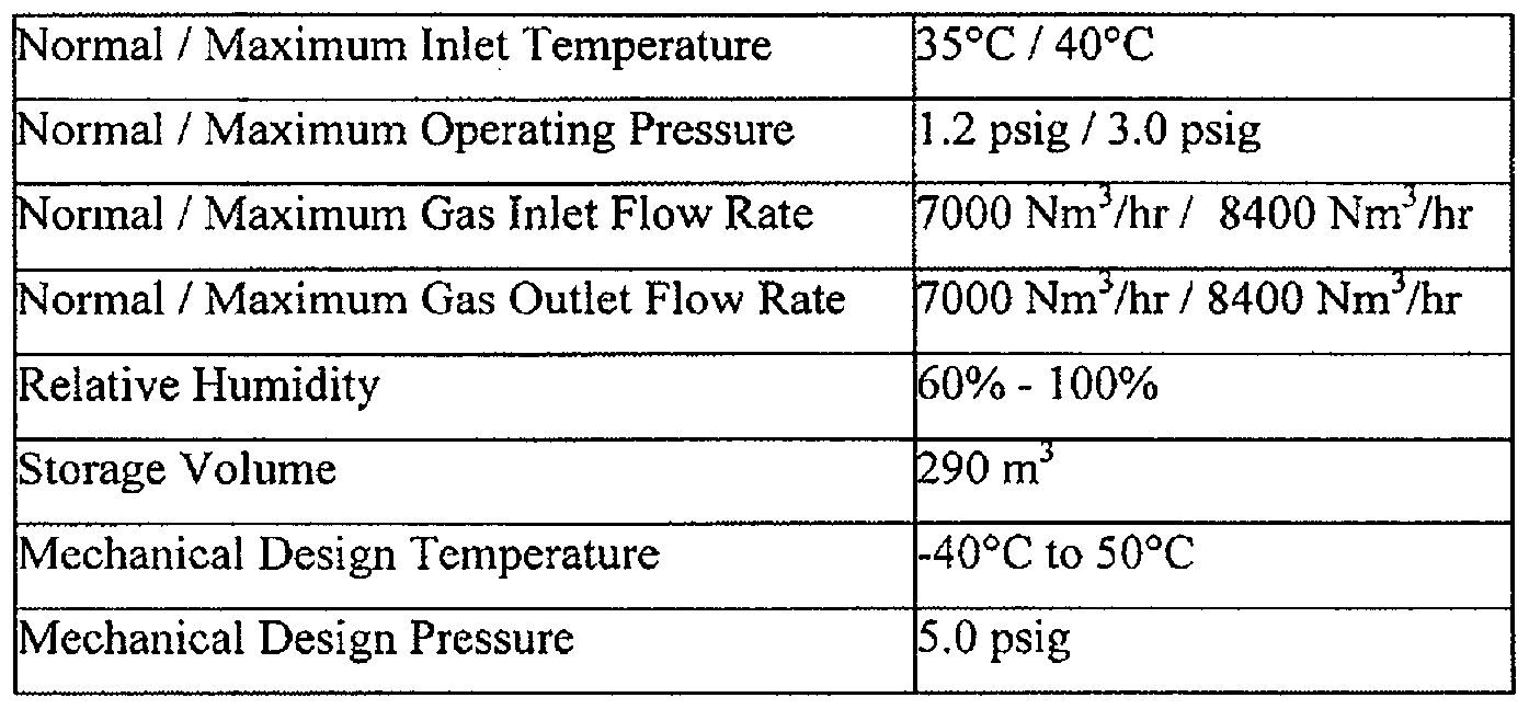
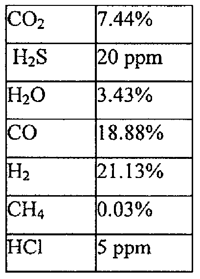

Claims
Priority Applications (30)
| Application Number | Priority Date | Filing Date | Title |
|---|---|---|---|
| JP2010547923A JP5547659B2 (en) | 2007-02-27 | 2008-02-27 | Gasification system with processing raw material / char conversion and gas reforming |
| US12/919,829 US8690975B2 (en) | 2007-02-27 | 2008-02-27 | Gasification system with processed feedstock/char conversion and gas reformulation |
| KR20107021454A KR20110000554A (en) | 2008-02-27 | 2008-02-27 | Gasification system with processed feedstock/char conversion and gas reformulation |
| BRPI0822209A BRPI0822209A2 (en) | 2007-02-27 | 2008-02-27 | gasification system with processed raw material / coal conversion and gas reformulation |
| EA201001377A EA201001377A1 (en) | 2007-02-27 | 2008-02-27 | MULTI-CHAMBER SYSTEM AND METHOD FOR CONVERTING CARBON-CONTAINING RAW MATERIALS INTO SYNTHESIS-GAS AND SLAG |
| EP08714677A EP2260241A4 (en) | 2007-02-27 | 2008-02-27 | Gasification system with processed feedstock/char conversion and gas reformulation |
| AU2008221197A AU2008221197B9 (en) | 2008-02-27 | 2008-02-27 | Gasification system with processed feedstock/char conversion and gas reformulation |
| CN2008801288729A CN102057222B (en) | 2007-02-27 | 2008-02-27 | Gasification system with processed feedstock/char conversion and gas reformulation |
| CA2716912A CA2716912C (en) | 2007-02-27 | 2008-02-27 | Gasification system with processed feedstock/char conversion and gas reformulation |
| US12/119,413 US20080277265A1 (en) | 2007-05-11 | 2008-05-12 | Gas reformulation system comprising means to optimize the effectiveness of gas conversion |
| US12/119,307 US20090020456A1 (en) | 2007-05-11 | 2008-05-12 | System comprising the gasification of fossil fuels to process unconventional oil sources |
| AU2008250931A AU2008250931B8 (en) | 2007-05-11 | 2008-05-12 | A gas reformulation system comprising means to optimize the effectiveness of gas conversion |
| GB1002402.4A GB2463850B (en) | 2007-05-11 | 2008-05-12 | A gas reformulation system comprising means to optimize the effectiveness of gas conversion |
| UY31081A UY31081A1 (en) | 2007-05-11 | 2008-05-12 | A GAS REFORMULATION SYSTEM UNDERSTANDING MEANS TO OPTIMIZE THE EFFECTIVENESS OF GAS CONVERSION |
| MYPI2010000234A MY150298A (en) | 2007-07-17 | 2008-05-12 | A gas reformulation system comprising means to optimize the efectiveness of gas conversion |
| PCT/CA2008/000883 WO2008138118A1 (en) | 2007-05-11 | 2008-05-12 | A system comprising the gasification of fossil fuels to process unconventional oil sources |
| ARP080102000A AR066535A1 (en) | 2007-05-11 | 2008-05-12 | AN INITIAL GAS REFORMULATION SYSTEM IN A REFORMULATED GAS AND PROCEDURE FOR SUCH REFORMULATION. |
| ARP080102008A AR066538A1 (en) | 2007-05-11 | 2008-05-12 | "AN INTEGRATED INSTALLATION FOR THE EXTRACTION OF USEFUL FUEL PRODUCTS FROM AN UNCONVENTIONAL PETROLEUM SOURCE AND A PROCESS TO PRODUCE FUEL PRODUCTS" |
| CA2723792A CA2723792A1 (en) | 2007-05-11 | 2008-05-12 | A system comprising the gasification of fossil fuels to process unconventional oil sources |
| JP2010516330A JP2010533742A (en) | 2007-07-17 | 2008-05-12 | Gas reforming system including means for optimizing the efficiency of gas conversion |
| CA2694243A CA2694243C (en) | 2007-07-17 | 2008-05-12 | A gas reformulation system comprising means to optimize the effectiveness of gas conversion |
| MX2010000616A MX2010000616A (en) | 2007-07-17 | 2008-05-12 | A gas reformulation system comprising means to optimize the effectiveness of gas conversion. |
| EP08748281A EP2183045A4 (en) | 2007-07-17 | 2008-05-12 | A gas reformulation system comprising means to optimize the effectiveness of gas conversion |
| TW097117480A TW200848151A (en) | 2007-05-11 | 2008-05-12 | A gas reformulation system comprising means to optimise the effectiveness of gas conversion |
| PCT/CA2008/000882 WO2008138117A1 (en) | 2007-05-11 | 2008-05-12 | A gas reformulation system comprising means to optimize the effectiveness of gas conversion |
| KR1020107003450A KR101338266B1 (en) | 2007-07-17 | 2008-05-12 | A gas reformulation system comprising means to optimize the effectiveness of gas conversion |
| CN2008801073712A CN101801515B (en) | 2007-07-17 | 2008-05-12 | A gas reformulation system comprising means to optimize the effectiveness of gas conversion |
| PE2008000824A PE20090264A1 (en) | 2007-05-11 | 2008-05-30 | A GAS REFORMULATION SYSTEM UNDERSTANDING WAYS TO OPTIMIZE THE EFFECTIVENESS OF GAS CONVERSION |
| ZA2010/01043A ZA201001043B (en) | 2007-07-17 | 2010-02-12 | A gas reformulation system comprising means to optimize the effectiveness of gas convertion |
| HK11112142A HK1157852A1 (en) | 2008-02-27 | 2011-11-10 | Gasification system with processed feedstock/char conversion and gas reformulation |
Applications Claiming Priority (18)
| Application Number | Priority Date | Filing Date | Title |
|---|---|---|---|
| US89175407P | 2007-02-27 | 2007-02-27 | |
| US89174907P | 2007-02-27 | 2007-02-27 | |
| US89176807P | 2007-02-27 | 2007-02-27 | |
| US89180707P | 2007-02-27 | 2007-02-27 | |
| US60/891,754 | 2007-02-27 | ||
| US60/891,768 | 2007-02-27 | ||
| US60/891,749 | 2007-02-27 | ||
| US60/891,807 | 2007-02-27 | ||
| PCT/US2007/068405 WO2007131239A2 (en) | 2006-05-05 | 2007-05-07 | A control system for the conversion of a carbonaceous feedstock into gas |
| USPCT/US2007/68405 | 2007-05-07 | ||
| PCT/US2007/068407 WO2008011213A2 (en) | 2006-05-05 | 2007-05-07 | A low temperature gasification facility with a horizontally oriented gasifier |
| USPCT/US2007/68407 | 2007-05-07 | ||
| US91739507P | 2007-05-11 | 2007-05-11 | |
| US60/917,395 | 2007-05-11 | ||
| PCT/US2007/070456 WO2007143673A1 (en) | 2006-06-05 | 2007-06-05 | A gasifier comprising vertically successive processing regions |
| USPCT/US2007/70456 | 2007-06-05 | ||
| US98612707P | 2007-11-07 | 2007-11-07 | |
| US60/986,127 | 2007-11-07 |
Publications (1)
| Publication Number | Publication Date |
|---|---|
| WO2008104058A1 true WO2008104058A1 (en) | 2008-09-04 |
Family
ID=39720807
Family Applications (1)
| Application Number | Title | Priority Date | Filing Date |
|---|---|---|---|
| PCT/CA2008/000355 WO2008104058A1 (en) | 2007-02-27 | 2008-02-27 | Gasification system with processed feedstock/char conversion and gas reformulation |
Country Status (8)
| Country | Link |
|---|---|
| US (1) | US8690975B2 (en) |
| EP (1) | EP2260241A4 (en) |
| JP (1) | JP5547659B2 (en) |
| CN (1) | CN102057222B (en) |
| BR (1) | BRPI0822209A2 (en) |
| CA (1) | CA2716912C (en) |
| EA (1) | EA201001377A1 (en) |
| WO (1) | WO2008104058A1 (en) |
Cited By (22)
| Publication number | Priority date | Publication date | Assignee | Title |
|---|---|---|---|---|
| EP2177590A1 (en) * | 2008-10-17 | 2010-04-21 | Resetec Patent Sarl | Method and apparatus for pyrolysis of a feed comprising hydrocarbons and gasification of a pyrolysis residue |
| DE102009017025B3 (en) * | 2009-04-14 | 2010-09-16 | EVZA Energie- und Verwertungszentrale GmbH, Anhalt | Method for removal of mercury from flue gas of e.g. waste incinerator, involves evaluating measuring signals such that monitoring of steep rising edge/deviation of mercury content is recognized by specific criteria |
| EP2236457A1 (en) * | 2009-03-30 | 2010-10-06 | Shell Internationale Research Maatschappij B.V. | Process for producing a purified synthesis gas |
| WO2010112502A1 (en) * | 2009-03-30 | 2010-10-07 | Shell Internationale Research Maatschappij B.V. | Process for producing a purified synthesis gas stream |
| WO2010121895A1 (en) * | 2009-03-30 | 2010-10-28 | Shell Internationale Research Maatschappij B.V. | Process for producing purified synthesis gas |
| WO2011003374A2 (en) * | 2009-07-08 | 2011-01-13 | Eurotherm Technologies Ag | Arrangement and method for preparing and thermally treating by-products and waste and method for operating said arrangement (thermal cracking method) |
| JP2011006576A (en) * | 2009-06-25 | 2011-01-13 | Nippon Steel Engineering Co Ltd | Emergency shutdown system for gasification facility |
| WO2011106895A1 (en) | 2010-03-01 | 2011-09-09 | Plasco Energy Group Inc. | Carbon conversion system with integrated processing zones |
| WO2011149819A1 (en) * | 2010-05-26 | 2011-12-01 | Exxonmobil Research And Engineering Company | Corrosion resistant gasifier components |
| ES2380143A1 (en) * | 2010-10-10 | 2012-05-09 | Gerindote Morillo, S.L. | Procedure for gasification of residues and corresponding installation for the execution of the same. (Machine-translation by Google Translate, not legally binding) |
| US8343241B2 (en) | 2009-02-11 | 2013-01-01 | Natural Energy Systems Inc. | Process for the conversion of organic material to methane rich fuel gas |
| WO2013142945A1 (en) * | 2012-03-29 | 2013-10-03 | Her Majesty The Queen In Right Of Canada As Represented By The Minister Of Natural Resources | Supplemental burner for conversion of biomass and related solid fuel |
| WO2013179313A1 (en) * | 2012-05-31 | 2013-12-05 | Wte Waste To Energy Canada, Inc | Advanced sequential batch gasification process |
| US20140045257A1 (en) * | 2009-06-11 | 2014-02-13 | Ineos Bio Limited | Methods for sequestering carbon dioxide into alcohols via gasification fermentation |
| US20140077133A1 (en) * | 2010-11-10 | 2014-03-20 | Air Products And Chemicals, Inc. | Syngas Produced By Plasma Gasification |
| US20150112114A1 (en) * | 2011-04-13 | 2015-04-23 | Alter Nrg Corp. | Process and apparatus for treatment of incinerator bottom ash and fly ash |
| US9150806B1 (en) | 2014-06-02 | 2015-10-06 | PHG Engery, LLC | Microwave induced plasma cleaning device and method for producer gas |
| WO2016112460A1 (en) * | 2015-01-14 | 2016-07-21 | Plasco Energy Group Inc. | Plasma-assisted method and system for treating raw syngas comprising tars |
| US9416328B2 (en) | 2010-01-06 | 2016-08-16 | General Electric Company | System and method for treatment of fine particulates separated from syngas produced by gasifier |
| EP3201125A4 (en) * | 2014-09-30 | 2018-05-02 | Plasco Conversion Technologies Inc. | A non-equilibrium plasma system and method of refining syngas |
| WO2020107090A1 (en) * | 2018-11-29 | 2020-06-04 | Petróleo Brasileiro S.A. - Petrobras | Process and plasma reactor for the production of synthesis gas |
| CN114409197A (en) * | 2022-01-29 | 2022-04-29 | 陕西东鑫垣化工有限责任公司 | Coke quenching closed type drying water-oil ammonia-sulfur component recycling treatment process |
Families Citing this family (121)
| Publication number | Priority date | Publication date | Assignee | Title |
|---|---|---|---|---|
| US7987613B2 (en) * | 2004-10-12 | 2011-08-02 | Great River Energy | Control system for particulate material drying apparatus and process |
| AU2007247895A1 (en) * | 2006-05-05 | 2007-11-15 | Plascoenergy Ip Holdings, S.L., Bilbao, Schaffhausen Branch | A gas homogenization system |
| NZ573217A (en) | 2006-05-05 | 2011-11-25 | Plascoenergy Ip Holdings S L Bilbao Schaffhausen Branch | A facility for conversion of carbonaceous feedstock into a reformulated syngas containing CO and H2 |
| CN101495808B (en) | 2006-05-05 | 2011-12-07 | 普拉斯科能源Ip控股公司毕尔巴鄂-沙夫豪森分公司 | A horizontally-oriented gasifier with lateral transfer system |
| WO2007131239A2 (en) | 2006-05-05 | 2007-11-15 | Plasco Energy Group Inc. | A control system for the conversion of a carbonaceous feedstock into gas |
| US8475551B2 (en) | 2006-05-05 | 2013-07-02 | Plasco Energy Group Inc. | Gas reformulating system using plasma torch heat |
| US20110062013A1 (en) * | 2007-02-27 | 2011-03-17 | Plasco Energy Group Inc. | Multi-Zone Carbon Conversion System with Plasma Melting |
| EP2260241A4 (en) | 2007-02-27 | 2012-03-28 | Plascoenergy Ip Holdings S L | Gasification system with processed feedstock/char conversion and gas reformulation |
| US20100162589A1 (en) * | 2007-07-19 | 2010-07-01 | Gedalyahu Manor | Method for processing and drying waste in a continuous process |
| US8151482B2 (en) * | 2008-11-25 | 2012-04-10 | William H Moss | Two-stage static dryer for converting organic waste to solid fuel |
| GB0902234D0 (en) * | 2009-02-11 | 2009-03-25 | Edwards Ltd | Method of treating an exhaust gas stream |
| WO2010141629A1 (en) | 2009-06-02 | 2010-12-09 | Thermochem Recovery International, Inc. | Gasifier having integrated fuel cell power generation system |
| US20100313442A1 (en) * | 2009-06-12 | 2010-12-16 | Steven Craig Russell | Method of using syngas cooling to heat drying gas for a dry feed system |
| BRPI0904780B1 (en) * | 2009-09-17 | 2017-05-30 | Petrocoque S/A Indústria e Comércio | Improvements in the feed media of a rotary kiln used for calcining green petroleum coke |
| US8940062B2 (en) * | 2009-10-28 | 2015-01-27 | Ihi Corporation | Method and apparatus for controlling temperature in combustion furnace in gasification equipment |
| MY153323A (en) * | 2010-03-01 | 2015-01-29 | Plascoenergy Ip Holdings Slb | A lateral transfer system |
| EP2547973B1 (en) * | 2010-03-15 | 2014-03-19 | Solaronics S.A. | Drying installation |
| WO2011126771A2 (en) * | 2010-03-27 | 2011-10-13 | Perfectly Green Corporation | System, method and computer program product for energy allocation |
| US8425637B2 (en) * | 2010-06-04 | 2013-04-23 | John R. Lersch | Process and system for converting waste material to fuel or synthetic gas feedstock |
| US20120023822A1 (en) * | 2010-07-29 | 2012-02-02 | Air Products And Chemicals, Inc. | Method and System for Controlled Gasification |
| US20120024843A1 (en) * | 2010-07-30 | 2012-02-02 | General Electric Company | Thermal treatment of carbonaceous materials |
| US9321640B2 (en) | 2010-10-29 | 2016-04-26 | Plasco Energy Group Inc. | Gasification system with processed feedstock/char conversion and gas reformulation |
| US9011561B2 (en) | 2010-11-05 | 2015-04-21 | Thermochem Recovery International, Inc. | Solids circulation system and method for capture and conversion of reactive solids |
| IT1403189B1 (en) * | 2011-01-05 | 2013-10-15 | High Tech En Sro | SYSTEM AND METHOD FOR THE PRODUCTION OF SYNGAS FROM CARBON-BASED MATERIAL |
| US20120210645A1 (en) * | 2011-02-17 | 2012-08-23 | Oaks Plasma Llc | Multi-ring Plasma Pyrolysis Chamber |
| WO2012122622A1 (en) * | 2011-03-17 | 2012-09-20 | Nexterra Systems Corp. | Control of syngas temperature using a booster burner |
| US9028571B2 (en) * | 2011-04-06 | 2015-05-12 | Ineos Bio Sa | Syngas cooler system and method of operation |
| WO2012142084A1 (en) | 2011-04-11 | 2012-10-18 | ADA-ES, Inc. | Fluidized bed method and system for gas component capture |
| US9499404B2 (en) | 2011-09-27 | 2016-11-22 | Thermochem Recovery International, Inc. | System and method for syngas clean-up |
| SG190503A1 (en) * | 2011-12-02 | 2013-06-28 | Lien Chiow Tan | Green engine |
| JP5642657B2 (en) * | 2011-12-06 | 2014-12-17 | 三菱重工業株式会社 | Fuel gasification system, control method and control program therefor, and fuel gasification combined power generation system including fuel gasification system |
| FR2985043B1 (en) * | 2011-12-21 | 2014-02-21 | Commissariat Energie Atomique | METHOD AND DEVICE FOR RAPID BIOMASS ROOFING |
| CN102618330B (en) * | 2011-12-29 | 2014-02-26 | 武汉凯迪工程技术研究总院有限公司 | High temperature normal pressure biomass gasification island process |
| CN102559273B (en) * | 2011-12-29 | 2014-03-05 | 武汉凯迪工程技术研究总院有限公司 | Microwave plasma biomass gasification fixed-bed gasification furnace and process |
| AU2013216767B2 (en) * | 2012-02-11 | 2017-05-18 | 8 Rivers Capital, Llc | Partial oxidation reaction with closed cycle quench |
| US9096807B2 (en) * | 2012-03-09 | 2015-08-04 | General Electric Company | Biomass gasifier with disruption device |
| US9366429B2 (en) | 2012-04-18 | 2016-06-14 | Farm Pilot Project Coordination, Inc. | Method and system for processing animal waste |
| CN104812467B (en) | 2012-09-20 | 2017-05-17 | Ada-Es股份有限公司 | Method and system to reclaim functional sites on sorbent contaminated by heat stable salts |
| US20140231417A1 (en) * | 2013-01-18 | 2014-08-21 | Cardinal Law Group | Integrated and modular approach for converting electrical power to ionic momentum and high differential voltage potential |
| US9453171B2 (en) * | 2013-03-07 | 2016-09-27 | General Electric Company | Integrated steam gasification and entrained flow gasification systems and methods for low rank fuels |
| US9453170B2 (en) * | 2013-03-15 | 2016-09-27 | All Power Labs, Inc. | Hybrid fixed-kinetic bed gasifier for fuel flexible gasification |
| US9834728B2 (en) | 2013-06-21 | 2017-12-05 | Karen Fleckner | Production of fuel |
| EP3041918A4 (en) | 2013-09-05 | 2017-08-30 | AG Energy Solutions, Inc. | Apparatuses, systems, mobile gasification systems, and methods for gasifying residual biomass |
| US10370539B2 (en) | 2014-01-30 | 2019-08-06 | Monolith Materials, Inc. | System for high temperature chemical processing |
| US10100200B2 (en) | 2014-01-30 | 2018-10-16 | Monolith Materials, Inc. | Use of feedstock in carbon black plasma process |
| US11939477B2 (en) | 2014-01-30 | 2024-03-26 | Monolith Materials, Inc. | High temperature heat integration method of making carbon black |
| US10138378B2 (en) | 2014-01-30 | 2018-11-27 | Monolith Materials, Inc. | Plasma gas throat assembly and method |
| US20150211378A1 (en) * | 2014-01-30 | 2015-07-30 | Boxer Industries, Inc. | Integration of plasma and hydrogen process with combined cycle power plant, simple cycle power plant and steam reformers |
| RU2016135213A (en) | 2014-01-31 | 2018-03-05 | Монолит Матириалз, Инк. | PLASMA BURNER DESIGN |
| CN103838265B (en) * | 2014-03-07 | 2016-09-28 | 西北化工研究院 | A kind of in the control system producing synthesis gas time control hydrogen and carbon monoxide ratio |
| US20150300637A1 (en) * | 2014-04-22 | 2015-10-22 | Magnegas Corporation | Incineration using Magnegas |
| US9683738B2 (en) * | 2014-06-16 | 2017-06-20 | Biomass Energy Enhancements, Llc | System for co-firing coal and beneficiated organic-carbon-containing feedstock in a coal combustion apparatus |
| US9702548B2 (en) * | 2014-06-16 | 2017-07-11 | Biomass Energy Enhancements, Llc | System for co-firing cleaned coal and beneficiated organic-carbon-containing feedstock in a coal combustion apparatus |
| US9631151B2 (en) | 2014-09-04 | 2017-04-25 | Ag Energy Solutions, Inc. | Apparatuses, systems, tar crackers, and methods for gasifying having at least two modes of operation |
| CN104457300B (en) * | 2014-12-12 | 2016-08-24 | 上海宝钢节能环保技术有限公司 | The comprehensive stepped utilization method of industrial waste heat resource |
| CA2975723C (en) | 2015-02-03 | 2023-08-22 | Monolith Materials, Inc. | Regenerative cooling method and apparatus |
| KR101795686B1 (en) * | 2015-05-27 | 2017-11-08 | 엄환섭 | Apparatus for production of hydrogen using microwave steam torch |
| EP3303810A1 (en) | 2015-05-29 | 2018-04-11 | Perfectly Green Corporation | System, method and computer program product for energy allocation |
| CN111601447A (en) | 2015-07-29 | 2020-08-28 | 巨石材料公司 | DC plasma torch power design method and apparatus |
| US10046274B2 (en) | 2015-08-28 | 2018-08-14 | Big Monkey Services, LLC. | Methods and systems for inhibiting crystalline buildup in a flue gas desulfurization unit |
| CN108352493B (en) | 2015-09-14 | 2022-03-08 | 巨石材料公司 | Production of carbon black from natural gas |
| JP2018538502A (en) * | 2015-09-24 | 2018-12-27 | レール・リキード−ソシエテ・アノニム・プール・レテュード・エ・レクスプロワタシオン・デ・プロセデ・ジョルジュ・クロード | Industrial furnace integrated with biomass gasification system |
| US9803150B2 (en) | 2015-11-03 | 2017-10-31 | Responsible Energy Inc. | System and apparatus for processing material to generate syngas in a modular architecture |
| CA3004164A1 (en) * | 2015-11-03 | 2017-05-11 | Responsible Energy Inc. | System and apparatus for processing material to generate syngas in a modular architecture |
| CN105688618B (en) * | 2016-01-19 | 2018-12-11 | 桂盟链条(太仓)有限公司 | A kind of heat treatment exhaust gas plasma-based recombination electricity-generating method and plasma-based recombining reaction device |
| US11242988B2 (en) | 2016-02-16 | 2022-02-08 | Thermochem Recovery International, Inc. | Two-stage energy-integrated product gas generation system and method |
| CA3018980C (en) | 2016-03-25 | 2019-04-16 | Thermochem Recovery International, Inc. | Three-stage energy-integrated product gas generation system and method |
| CA3060565C (en) | 2016-04-29 | 2024-03-12 | Monolith Materials, Inc. | Torch stinger method and apparatus |
| MX2018013162A (en) | 2016-04-29 | 2019-07-04 | Monolith Mat Inc | Secondary heat addition to particle production process and apparatus. |
| US10227247B2 (en) | 2016-05-26 | 2019-03-12 | Big Monkey Services, Llc | Methods and systems for remediation of heavy metals in combustion waste |
| CN107616722B (en) * | 2016-07-13 | 2021-07-20 | 广东美的生活电器制造有限公司 | Food processor and anti-overflow detection method |
| RU2632825C1 (en) * | 2016-08-12 | 2017-10-10 | Общество с ограниченной ответственностью "Генератор синтез-газа" | Method for controlling synthesis gas production process |
| US10197014B2 (en) | 2016-08-30 | 2019-02-05 | Thermochem Recovery International, Inc. | Feed zone delivery system having carbonaceous feedstock density reduction and gas mixing |
| US10197015B2 (en) | 2016-08-30 | 2019-02-05 | Thermochem Recovery International, Inc. | Feedstock delivery system having carbonaceous feedstock splitter and gas mixing |
| US10364398B2 (en) | 2016-08-30 | 2019-07-30 | Thermochem Recovery International, Inc. | Method of producing product gas from multiple carbonaceous feedstock streams mixed with a reduced-pressure mixing gas |
| US11634651B2 (en) * | 2016-09-08 | 2023-04-25 | Waste to Energy Systems, LLC | System and method for biogasification |
| US10308512B2 (en) | 2016-10-06 | 2019-06-04 | Lyten, Inc. | Microwave reactor system with gas-solids separation |
| IT201600111822A1 (en) * | 2016-11-07 | 2018-05-07 | Reset S R L | WOOD BIOMASS COGENERATION PLANT FOR CONTINUOUS PRODUCTION OF HEAT AND ELECTRICITY. |
| IL249923B (en) * | 2017-01-03 | 2018-03-29 | Shohat Tsachi | Smart waste container |
| US9997334B1 (en) | 2017-02-09 | 2018-06-12 | Lyten, Inc. | Seedless particles with carbon allotropes |
| CN107033962B (en) * | 2017-02-09 | 2023-08-04 | 北京四维天拓技术有限公司 | Stepped gasification chamber |
| US10421981B2 (en) | 2017-02-21 | 2019-09-24 | Big Monkey Services, Llc | Methods and systems for producing short chain weak organic acids from carbon dioxide |
| UA115017C2 (en) | 2017-03-07 | 2017-08-28 | Савелій Дмитрович Федоров | SOLID FUEL GASIFICATION METHOD AND GASIFIER COMBINED SOLID FUEL FOR ITS PERFORMANCE |
| MX2019010619A (en) | 2017-03-08 | 2019-12-19 | Monolith Mat Inc | Systems and methods of making carbon particles with thermal transfer gas. |
| WO2018169889A1 (en) | 2017-03-16 | 2018-09-20 | Lyten, Inc. | Carbon and elastomer integration |
| US10920035B2 (en) | 2017-03-16 | 2021-02-16 | Lyten, Inc. | Tuning deformation hysteresis in tires using graphene |
| US10329506B2 (en) | 2017-04-10 | 2019-06-25 | Thermochem Recovery International, Inc. | Gas-solids separation system having a partitioned solids transfer conduit |
| EP3612600A4 (en) | 2017-04-20 | 2021-01-27 | Monolith Materials, Inc. | Particle systems and methods |
| CN106977039B (en) * | 2017-04-28 | 2023-10-17 | 德阳市耀群机电配套有限公司 | Cyclone magnetic filter |
| CN107063778B (en) * | 2017-05-10 | 2024-03-08 | 张家港市华昌新材料科技有限公司 | Propylene online internal circulation type closed sampling system and method |
| US10717102B2 (en) | 2017-05-31 | 2020-07-21 | Thermochem Recovery International, Inc. | Pressure-based method and system for measuring the density and height of a fluidized bed |
| US9920926B1 (en) | 2017-07-10 | 2018-03-20 | Thermochem Recovery International, Inc. | Pulse combustion heat exchanger system and method |
| SG11202001736QA (en) | 2017-08-30 | 2020-03-30 | Circular Resources Ip Pte Ltd | Waste processing system |
| CN107450501A (en) * | 2017-09-14 | 2017-12-08 | 长春北方化工灌装设备股份有限公司 | A kind of manufacturing execution system for being applied to automate filling workshop |
| US10099200B1 (en) | 2017-10-24 | 2018-10-16 | Thermochem Recovery International, Inc. | Liquid fuel production system having parallel product gas generation |
| WO2019084200A1 (en) | 2017-10-24 | 2019-05-02 | Monolith Materials, Inc. | Particle systems and methods |
| RU181126U1 (en) * | 2017-11-28 | 2018-07-04 | Федеральное государственное автономное образовательное учреждение высшего образования "Уральский федеральный университет имени первого Президента России Б.Н. Ельцина" | Vortex Gas Generator |
| US10756334B2 (en) | 2017-12-22 | 2020-08-25 | Lyten, Inc. | Structured composite materials |
| CN112105922A (en) | 2018-01-04 | 2020-12-18 | 利腾股份有限公司 | Resonant gas sensor |
| CN107935861A (en) * | 2018-01-21 | 2018-04-20 | 宁波工程学院 | The apparatus and method of the non-equilibrium catalytic reaction of ethamine |
| RU2688737C1 (en) * | 2018-08-24 | 2019-05-22 | Федеральное государственное бюджетное образовательное учреждение высшего образования "Кубанский государственный технологический университет" (ФГБОУ ВО "КубГТУ") | Synthetic gas production method |
| CN109133004B (en) * | 2018-09-25 | 2022-02-25 | 浙江工业职业技术学院 | Hydrogen manufacturing equipment for hydrogen energy power automobile |
| CN109451614B (en) * | 2018-12-26 | 2024-02-23 | 通达(厦门)精密橡塑有限公司 | Independent grouping variable power non-contact type insert heating device and method |
| CN110011330B (en) * | 2019-03-13 | 2020-05-15 | 西安交通大学 | Primary frequency modulation optimization control method based on coal-fired unit thermodynamic system accumulation correction |
| US20220135893A1 (en) * | 2019-03-29 | 2022-05-05 | Eastman Chemical Company | Gasification of densified textiles and solid fossil fuels |
| CN110173702B (en) * | 2019-05-14 | 2023-12-05 | 中国空分工程有限公司 | VOCs pre-collection treatment system with water seal and treatment method thereof |
| RU2732808C1 (en) * | 2019-12-25 | 2020-09-22 | Федеральное государственное бюджетное образовательное учреждение высшего образования "Кубанский государственный технологический университет" (ФГБОУ ВО "КубГТУ") | Synthesis gas production method |
| US11555157B2 (en) | 2020-03-10 | 2023-01-17 | Thermochem Recovery International, Inc. | System and method for liquid fuel production from carbonaceous materials using recycled conditioned syngas |
| CN111792814B (en) * | 2020-08-11 | 2021-07-30 | 华电电力科学研究院有限公司 | Fly ash municipal sludge treatment method and system |
| CN111961502B (en) * | 2020-08-13 | 2021-09-10 | 广东洁冠科技有限公司 | Saturated steam process for biomass fuel processing |
| US11466223B2 (en) * | 2020-09-04 | 2022-10-11 | Thermochem Recovery International, Inc. | Two-stage syngas production with separate char and product gas inputs into the second stage |
| CN113204582B (en) * | 2021-03-26 | 2023-09-26 | 宝丰县海通道路材料有限公司 | Highway concrete performance detection system and detection method |
| CN113091808A (en) * | 2021-03-29 | 2021-07-09 | 江苏利宏科技发展有限公司 | Chemical industry industrial control instrument with comprehensive information management system and system thereof |
| CN113531538A (en) * | 2021-06-08 | 2021-10-22 | 湖南省欣洁环保科技有限公司 | Household garbage treatment method and system |
| CN114044488B (en) * | 2021-09-30 | 2023-05-26 | 万华化学集团股份有限公司 | Resource utilization method of byproduct carbon black generated in preparation of acetylene by natural gas and gasifier burner |
| CA3236636A1 (en) * | 2021-11-02 | 2023-05-11 | Universiteit Antwerpen | Device and method for gas conversion |
| CN113956051B (en) * | 2021-11-26 | 2023-03-21 | 厦门钜瓷科技有限公司 | Decarbonization method for preparing aluminum nitride powder by carbothermic method |
| CN114323720B (en) * | 2021-12-20 | 2022-11-01 | 武汉大学 | Clay effect sealing barrier effect and gas purification treatment test device and method |
| US11827859B1 (en) | 2022-05-03 | 2023-11-28 | NuPhY, Inc. | Biomass gasifier system with rotating distribution manifold |
| CN114890647B (en) * | 2022-05-06 | 2023-07-25 | 常熟市标准件厂有限公司 | Quick drying method and device for bolt galvanized sludge |
| KR102531657B1 (en) * | 2022-06-13 | 2023-05-10 | 심언규 | Apparatus for continuously manufacturing charcoal with carbonizing furnace |
Citations (3)
| Publication number | Priority date | Publication date | Assignee | Title |
|---|---|---|---|---|
| US6084139A (en) * | 1997-12-05 | 2000-07-04 | Gibros Pec B.V. | Method for processing waste or biomass material |
| CA2501841A1 (en) * | 2004-03-23 | 2005-09-23 | Central Research Institute Of Electric Power Industry | Carbonization and gasification of biomass and power generation system |
| WO2005118750A1 (en) * | 2004-06-01 | 2005-12-15 | Japan Science And Technology Agency | Solid-fuel gasification system |
Family Cites Families (165)
| Publication number | Priority date | Publication date | Assignee | Title |
|---|---|---|---|---|
| GB191300500A (en) | 1913-01-07 | 1913-10-23 | Godfrey Meynell Selwin Tait | Improvements in or relating to Gas Producers. |
| US1962958A (en) | 1932-07-19 | 1934-06-12 | Ephraim E Jones | Grate structure |
| GB683647A (en) | 1950-09-06 | 1952-12-03 | C Otto And Comp G M B H Dr | Improvements in or relating to the production of gas |
| US3622493A (en) * | 1968-01-08 | 1971-11-23 | Francois A Crusco | Use of plasma torch to promote chemical reactions |
| US3725020A (en) * | 1970-08-05 | 1973-04-03 | Texaco Inc | Fuel composition for producing synthesis gas or fuel gas |
| US3692505A (en) * | 1971-04-05 | 1972-09-19 | Consolidation Coal Co | Fixed bed coal gasification |
| US3801469A (en) * | 1971-08-31 | 1974-04-02 | Scient Res Instr Corp | Method for effecting chemical reactions between cascading solids and counterflowing gases or fluids |
| BE793881A (en) * | 1972-01-11 | 1973-07-11 | Westinghouse Electric Corp | APPARATUS FOR DESULFURIZATION AND COMPLETE CARBONATION |
| US3779182A (en) | 1972-08-24 | 1973-12-18 | S Camacho | Refuse converting method and apparatus utilizing long arc column forming plasma torches |
| AR205469A1 (en) * | 1974-07-04 | 1976-05-07 | Kiener Karl | PROCEDURE AND DEVICE FOR OBTAINING COMBUSTIBLE GAS |
| US3991557A (en) * | 1974-07-22 | 1976-11-16 | Donath Ernest E | Process for converting high sulfur coal to low sulfur power plant fuel |
| US4007786A (en) * | 1975-07-28 | 1977-02-15 | Texaco Inc. | Secondary recovery of oil by steam stimulation plus the production of electrical energy and mechanical power |
| US4181504A (en) * | 1975-12-30 | 1980-01-01 | Technology Application Services Corp. | Method for the gasification of carbonaceous matter by plasma arc pyrolysis |
| US4063521A (en) | 1976-08-19 | 1977-12-20 | Econo-Therm Energy Systems Corporation | Incinerator having gas flow controlling separator |
| US4141694A (en) * | 1977-08-26 | 1979-02-27 | Technology Application Services Corporation | Apparatus for the gasification of carbonaceous matter by plasma arc pyrolysis |
| US4229184A (en) * | 1979-04-13 | 1980-10-21 | The United States Of America As Represented By The United States Department Of Energy | Apparatus and method for solar coal gasification |
| US4272255A (en) * | 1979-07-19 | 1981-06-09 | Mountain Fuel Resources, Inc. | Apparatus for gasification of carbonaceous solids |
| US4291636A (en) * | 1980-05-29 | 1981-09-29 | Union Carbide Corporation | Solid refuse disposal process |
| US4400179A (en) * | 1980-07-14 | 1983-08-23 | Texaco Inc. | Partial oxidation high turndown apparatus |
| FR2487847A1 (en) | 1980-07-30 | 1982-02-05 | Cneema | PROCESS AND PLANT FOR GASIFICATION OF MATERIALS OF PLANT ORIGIN |
| US4399314A (en) * | 1982-02-01 | 1983-08-16 | Texaco Development Corporation | Process for the production of fuels from tar sands |
| NL8200417A (en) | 1982-02-04 | 1983-09-01 | Tab B V | Wood-fuelled gas generator supplying IC engine - has annular combustion zone with variable cross=section passing fuel to reduction zone |
| US4479443A (en) * | 1982-03-08 | 1984-10-30 | Inge Faldt | Method and apparatus for thermal decomposition of stable compounds |
| DE3217483A1 (en) * | 1982-05-10 | 1984-02-09 | Shell Internationale Research Maatschappij B.V., 2501 Den Haag | METHOD FOR RELEASING PRESSURE FROM FLIGHT ASH |
| US4489562A (en) | 1982-11-08 | 1984-12-25 | Combustion Engineering, Inc. | Method and apparatus for controlling a gasifier |
| US4676805A (en) * | 1983-05-31 | 1987-06-30 | Texaco Inc. | Process for operating a gas generator |
| US4495873A (en) * | 1983-07-26 | 1985-01-29 | Research Products/Blankenship Corporation | Incinerator for burning odor forming materials |
| US4543940A (en) * | 1983-08-16 | 1985-10-01 | Gas Research Institute | Segmented radiant burner assembly and combustion process |
| CA1225441A (en) * | 1984-01-23 | 1987-08-11 | Edward S. Fox | Plasma pyrolysis waste destruction |
| FR2559776B1 (en) | 1984-02-16 | 1987-07-17 | Creusot Loire | SYNTHESIS GAS PRODUCTION PROCESS |
| US4656956A (en) * | 1984-09-21 | 1987-04-14 | Flickinger Dale M | Furnace with oscillating grate |
| JPS61179399A (en) | 1985-02-05 | 1986-08-12 | 大蔵省印刷局長 | Papermaking fiber having photochromic substance adhered thereto |
| CA1265760A (en) * | 1985-07-29 | 1990-02-13 | Reginald D. Richardson | Process utilizing pyrolyzation and gasification for the synergistic co-processing of a combined feedstock of coal and heavy oil to produce a synthetic crude oil |
| US4666462A (en) * | 1986-05-30 | 1987-05-19 | Texaco Inc. | Control process for gasification of solid carbonaceous fuels |
| US4749383A (en) | 1986-06-04 | 1988-06-07 | Mansfield Carbon Products | Method for producing low and medium BTU gas from coal |
| FR2610087B1 (en) * | 1987-01-22 | 1989-11-24 | Aerospatiale | PROCESS AND DEVICE FOR THE DESTRUCTION OF SOLID WASTE BY PYROLYSIS |
| US5136137A (en) | 1987-05-04 | 1992-08-04 | Retech, Inc. | Apparatus for high temperature disposal of hazardous waste materials |
| JP2504504B2 (en) * | 1988-01-29 | 1996-06-05 | 財団法人半導体研究振興会 | Photoelectric conversion device |
| EP0330872A3 (en) | 1988-03-02 | 1990-09-12 | Westinghouse Electric Corporation | Method for continuous agglomeration of heavy metals contained in incinerator ash |
| US4881947A (en) * | 1988-06-28 | 1989-11-21 | Parker Thomas H | High efficiency gasifier with recycle system |
| US4838898A (en) * | 1988-06-30 | 1989-06-13 | Shell Oil Company | Method of removal and disposal of fly ash from a high-temperature, high-pressure synthesis gas stream |
| US5010829A (en) * | 1988-09-15 | 1991-04-30 | Prabhakar Kulkarni | Method and apparatus for treatment of hazardous waste in absence of oxygen |
| JPH02216810A (en) | 1989-02-17 | 1990-08-29 | Elna Co Ltd | Manufacture of aluminum foil for electrolytic capacitor |
| DE3926575A1 (en) | 1989-08-11 | 1991-02-14 | Metallgesellschaft Ag | PROCESS FOR CLEANING RAW FUEL GAS FROM THE GASIFICATION OF SOLID FUELS |
| US4989522A (en) * | 1989-08-11 | 1991-02-05 | Sharpe Environmental Services | Method and system for incineration and detoxification of semiliquid waste |
| US4960380A (en) * | 1989-09-21 | 1990-10-02 | Phoenix Environmental Ltd. | Method and apparatus for the reduction of solid waste material using coherent radiation |
| US4941415A (en) * | 1989-11-02 | 1990-07-17 | Entech Corporation | Municipal waste thermal oxidation system |
| JPH07111247B2 (en) * | 1989-11-10 | 1995-11-29 | 石川島播磨重工業株式会社 | Waste treatment method |
| FI85186C (en) * | 1989-12-07 | 1996-02-13 | Ahlstroem Oy | Method and apparatus for feeding fuel into a pressurized space |
| CA2006139C (en) * | 1989-12-20 | 1995-08-29 | Robert A. Ritter | Lined hazardous waste incinerator |
| US5095828A (en) * | 1990-12-11 | 1992-03-17 | Environmental Thermal Systems, Corp. | Thermal decomposition of waste material |
| WO1992011492A1 (en) * | 1990-12-21 | 1992-07-09 | Emu.Dee.Aru Co., Ltd. | Dry distillation gasification combustion apparatus with dry distillation gas producer and combustion gas burner section |
| US5101739A (en) * | 1991-01-04 | 1992-04-07 | Utah Environmental Energy, Inc. | Tire gassification and combustion system |
| US5319176A (en) * | 1991-01-24 | 1994-06-07 | Ritchie G. Studer | Plasma arc decomposition of hazardous wastes into vitrified solids and non-hazardous gasses |
| US5288969A (en) * | 1991-08-16 | 1994-02-22 | Regents Of The University Of California | Electrodeless plasma torch apparatus and methods for the dissociation of hazardous waste |
| US5280757A (en) * | 1992-04-13 | 1994-01-25 | Carter George W | Municipal solid waste disposal process |
| JP3284606B2 (en) | 1992-09-24 | 2002-05-20 | 石川島播磨重工業株式会社 | Ash melting furnace |
| US5279234A (en) * | 1992-10-05 | 1994-01-18 | Chiptec Wood Energy Systems | Controlled clean-emission biomass gasification heating system/method |
| US5937652A (en) * | 1992-11-16 | 1999-08-17 | Abdelmalek; Fawzy T. | Process for coal or biomass fuel gasification by carbon dioxide extracted from a boiler flue gas stream |
| US5579705A (en) | 1993-03-08 | 1996-12-03 | Kabushiki Kaisha Kobe Seiko Sho | Plasma furnace and a method of operating the same |
| EP0625869B1 (en) | 1993-05-19 | 2001-09-05 | Johns Manville International, Inc. | Method for the melting, combustion or incineration of materials and apparatus therefor |
| FR2709980B1 (en) | 1993-09-16 | 1995-10-27 | Commissariat Energie Atomique | Device for eliminating soot present in combustion effluents by sliding electrical discharges. |
| US5417170A (en) * | 1993-09-17 | 1995-05-23 | Eshleman; Roger D. | Sloped-bottom pyrolysis chamber and solid residue collection system in a material processing apparatus |
| US5361709A (en) * | 1993-09-17 | 1994-11-08 | Eshleman Roger D | Material transport pusher mechanism in a material processing apparatus |
| JP2853548B2 (en) | 1993-12-27 | 1999-02-03 | 日本鋼管株式会社 | Vertical coal pyrolysis unit |
| US5410121A (en) * | 1994-03-09 | 1995-04-25 | Retech, Inc. | System for feeding toxic waste drums into a treatment chamber |
| FR2718223B1 (en) | 1994-03-29 | 1996-06-21 | Babcock Entreprise | Device for charging large solid fuels into a fireplace, for example whole used tires. |
| US5477790A (en) | 1994-09-30 | 1995-12-26 | Foldyna; Joseph T. | Multistage system for solid waste burning and vitrification |
| US5798497A (en) * | 1995-02-02 | 1998-08-25 | Battelle Memorial Institute | Tunable, self-powered integrated arc plasma-melter vitrification system for waste treatment and resource recovery |
| US5847353A (en) * | 1995-02-02 | 1998-12-08 | Integrated Environmental Technologies, Llc | Methods and apparatus for low NOx emissions during the production of electricity from waste treatment systems |
| US6084147A (en) * | 1995-03-17 | 2000-07-04 | Studsvik, Inc. | Pyrolytic decomposition of organic wastes |
| RU2125082C1 (en) | 1995-04-04 | 1999-01-20 | Малое инновационное научно-производственное предприятие "Колорит" | Method and power-process plant for thermally processing solid fuel |
| US5634281A (en) * | 1995-05-15 | 1997-06-03 | Universal Drying Systems, Inc. | Multi pass, continuous drying apparatus |
| JPH0933028A (en) | 1995-07-20 | 1997-02-07 | Daido Steel Co Ltd | Ash melting furnace |
| US5544597A (en) | 1995-08-29 | 1996-08-13 | Plasma Technology Corporation | Plasma pyrolysis and vitrification of municipal waste |
| JPH09101399A (en) | 1995-10-02 | 1997-04-15 | Japan Atom Power Co Ltd:The | Method for melting waste and method and decomposer for melting, oxidizing and decomposing it |
| US5731564A (en) * | 1996-02-05 | 1998-03-24 | Mse, Inc. | Method of operating a centrifugal plasma arc furnace |
| US6112677A (en) * | 1996-03-07 | 2000-09-05 | Sevar Entsorgungsanlagen Gmbh | Down-draft fixed bed gasifier system and use thereof |
| US5727903A (en) * | 1996-03-28 | 1998-03-17 | Genesis Energy Systems, Inc. | Process and apparatus for purification and compression of raw landfill gas for vehicle fuel |
| JP3750881B2 (en) | 1996-06-12 | 2006-03-01 | 石川島播磨重工業株式会社 | Ash melting furnace |
| CA2188357C (en) | 1996-10-21 | 1999-09-07 | Peter G. Tsantrizos | plasma gasification and vitrification of ashes |
| JPH10132230A (en) | 1996-10-31 | 1998-05-22 | Ngk Insulators Ltd | Waste melting furnace and waste melting method |
| DE19652770A1 (en) | 1996-12-18 | 1998-06-25 | Metallgesellschaft Ag | Process for gasifying solid fuels in the circulating fluidized bed |
| FR2757499B1 (en) * | 1996-12-24 | 2001-09-14 | Etievant Claude | HYDROGEN GENERATOR |
| US5944034A (en) * | 1997-03-13 | 1999-08-31 | Mcnick Recycling, Inc. | Apparatus and method for recycling oil laden waste materials |
| US5865206A (en) * | 1997-05-09 | 1999-02-02 | Praxair Technology, Inc. | Process and apparatus for backing-up or supplementing a gas supply system |
| TW352346B (en) * | 1997-05-29 | 1999-02-11 | Ebara Corp | Method and device for controlling operation of melting furnace |
| US6155182A (en) | 1997-09-04 | 2000-12-05 | Tsangaris; Andreas | Plant for gasification of waste |
| US6200430B1 (en) * | 1998-01-16 | 2001-03-13 | Edgar J. Robert | Electric arc gasifier method and equipment |
| WO2000013785A1 (en) | 1998-09-02 | 2000-03-16 | Jacobus Swanepoel | Treatment of solid carbonaceous material |
| US6269286B1 (en) * | 1998-09-17 | 2001-07-31 | Texaco Inc. | System and method for integrated gasification control |
| CN1249207C (en) | 1998-11-05 | 2006-04-05 | 株式会社荏原制作所 | Power generation system based on gasification of combustible material |
| US6250236B1 (en) * | 1998-11-09 | 2001-06-26 | Allied Technology Group, Inc. | Multi-zoned waste processing reactor system with bulk processing unit |
| EP1004746A1 (en) | 1998-11-27 | 2000-05-31 | Shell Internationale Researchmaatschappij B.V. | Process for the production of liquid hydrocarbons |
| CN1098911C (en) | 1998-12-30 | 2003-01-15 | 中国科学院广州能源研究所 | Biomass gasifying and purifying circular fluid-bed system |
| US6089169A (en) * | 1999-03-22 | 2000-07-18 | C.W. Processes, Inc. | Conversion of waste products |
| DE19916931C2 (en) | 1999-03-31 | 2001-07-05 | Deponie Wirtschaft Umweltschut | Air supply pipe for a gasifier for generating fuel gas |
| DE60015129T2 (en) | 1999-05-21 | 2006-03-09 | Ebara Corp. | SYSTEM FOR GENERATING ELECTRICAL ENERGY BY MEANS OF GASIFICATION |
| US6394042B1 (en) * | 1999-09-08 | 2002-05-28 | Callabresi Combustion Systems, Inc | Gas fired tube and shell heat exchanger |
| TWI241392B (en) | 1999-09-20 | 2005-10-11 | Japan Science & Tech Agency | Apparatus and method for gasifying solid or liquid fuel |
| US6182584B1 (en) * | 1999-11-23 | 2001-02-06 | Environmental Solutions & Technology, Inc. | Integrated control and destructive distillation of carbonaceous waste |
| JP2001158887A (en) | 1999-12-01 | 2001-06-12 | Takeshi Hatanaka | Method and apparatus for producing synthetic natural gas |
| US6357526B1 (en) | 2000-03-16 | 2002-03-19 | Kellogg Brown & Root, Inc. | Field upgrading of heavy oil and bitumen |
| FI108258B (en) | 2000-04-26 | 2001-12-14 | Topi Paemppi | A method for moving a stepped grate in a solid fuel furnace |
| DE10047787A1 (en) | 2000-09-20 | 2002-03-28 | Ver Energiewerke Ag | Production of fuel gas by total gasification of household waste, pyrolyzes, further gasifies both condensate and coke, then combines all resultant permanent gases |
| CN1133039C (en) * | 2000-10-25 | 2003-12-31 | 清华大学 | Method and system of controlling generation and diffusion of dioxin and heavy metal during garbage incineration |
| ES2343167T3 (en) * | 2000-12-04 | 2010-07-26 | Emery Energy Company L.L.C. | GASIFICATOR OF MULTIPLE FACETS AND RELATED PROCEDURES. |
| JP3973840B2 (en) * | 2001-01-18 | 2007-09-12 | 独立行政法人科学技術振興機構 | Solid fuel gasifier |
| JP2002226877A (en) | 2001-01-29 | 2002-08-14 | Takeshi Hatanaka | Method and equipment for producing alternative natural gas equipment |
| US7229483B2 (en) | 2001-03-12 | 2007-06-12 | Frederick Michael Lewis | Generation of an ultra-superheated steam composition and gasification therewith |
| ITRM20010288A1 (en) | 2001-05-28 | 2002-11-28 | Ct Sviluppo Materiali Spa | CONTINUOUS PROCESSING PROCESS OF WASTE IN ORDER TO OBTAIN CONTROLLED COMPOSITION PROCEDURES AND SUITABLE PLASMA REACTOR |
| US7100692B2 (en) | 2001-08-15 | 2006-09-05 | Shell Oil Company | Tertiary oil recovery combined with gas conversion process |
| DE60115109T2 (en) | 2001-08-22 | 2006-08-03 | Solena Group, Inc. | PLASMAPYROLYSIS, GASIFICATION AND GLAZING OF ORGANIC MATERIALS |
| US6987792B2 (en) * | 2001-08-22 | 2006-01-17 | Solena Group, Inc. | Plasma pyrolysis, gasification and vitrification of organic material |
| AU2002324270B2 (en) | 2001-08-22 | 2007-10-11 | Sasol Technology (Proprietary) Limited | Production of synthesis gas and synthesis gas derived products |
| CA2461716A1 (en) | 2001-09-28 | 2003-04-10 | Ebara Corporation | Combustible gas reforming method and combustible gas reforming apparatus and gasification apparatus |
| US6485296B1 (en) * | 2001-10-03 | 2002-11-26 | Robert J. Bender | Variable moisture biomass gasification heating system and method |
| US20030070808A1 (en) | 2001-10-15 | 2003-04-17 | Conoco Inc. | Use of syngas for the upgrading of heavy crude at the wellhead |
| US6863268B2 (en) * | 2001-11-27 | 2005-03-08 | Chaojiong Zhang | Dew point humidifier (DPH) and related gas temperature control |
| AU2003215059B2 (en) * | 2002-02-05 | 2007-03-22 | The Regents Of The University Of California | Production of synthetic transportation fuels from carbonaceous materials using self-sustained hydro-gasification |
| JP2003227349A (en) | 2002-02-07 | 2003-08-15 | Mitsui Eng & Shipbuild Co Ltd | Biomass gasification generating set |
| IL148223A (en) * | 2002-02-18 | 2009-07-20 | David Pegaz | System for a waste processing plant |
| JP2003260454A (en) | 2002-03-12 | 2003-09-16 | Mitsui Eng & Shipbuild Co Ltd | Method and apparatus for pyrolysis of biomass |
| ES2273023T3 (en) * | 2002-04-05 | 2007-05-01 | Shell Internationale Research Maatschappij B.V. | METHOD TO CONTROL A PROCEDURE. |
| US6953045B2 (en) * | 2002-04-10 | 2005-10-11 | Neil Enerson | Gas delivery system |
| CN100413564C (en) | 2002-05-08 | 2008-08-27 | 刘健安 | Hazardous waste treatment method and apparatus |
| US6938562B2 (en) * | 2002-05-17 | 2005-09-06 | Senreq, Llc | Apparatus for waste gasification |
| US6887284B2 (en) * | 2002-07-12 | 2005-05-03 | Dannie B. Hudson | Dual homogenization system and process for fuel oil |
| CA2418836A1 (en) * | 2003-02-12 | 2004-08-12 | Resorption Canada Ltd. | Multiple plasma generator hazardous waste processing system |
| CA2424805C (en) | 2003-04-04 | 2009-05-26 | Pyrogenesis Inc. | Two-stage plasma process for converting waste into fuel gas and apparatus therefor |
| US7056487B2 (en) | 2003-06-06 | 2006-06-06 | Siemens Power Generation, Inc. | Gas cleaning system and method |
| US7279655B2 (en) | 2003-06-11 | 2007-10-09 | Plasmet Corporation | Inductively coupled plasma/partial oxidation reformation of carbonaceous compounds to produce fuel for energy production |
| JP2005139338A (en) | 2003-11-07 | 2005-06-02 | Mitsui Eng & Shipbuild Co Ltd | Method for measuring temperature of burning zone of moving bed-type gasification furnace and apparatus for gasifying waste |
| US7241322B2 (en) * | 2003-11-21 | 2007-07-10 | Graham Robert G | Pyrolyzing gasification system and method of use |
| US6971323B2 (en) | 2004-03-19 | 2005-12-06 | Peat International, Inc. | Method and apparatus for treating waste |
| US7381320B2 (en) * | 2004-08-30 | 2008-06-03 | Kellogg Brown & Root Llc | Heavy oil and bitumen upgrading |
| KR100622297B1 (en) | 2004-09-23 | 2006-09-19 | 씨이테크 | Tiered semi-continuous dry distillation incinerator |
| CN1262627C (en) | 2004-12-16 | 2006-07-05 | 太原理工大学 | Oven gas generation of plasma gasified coke oven |
| EP1696177A1 (en) | 2005-02-28 | 2006-08-30 | Drechsler, Daniel | Integrated multifuel gasification process |
| JPWO2006114818A1 (en) | 2005-04-01 | 2008-12-11 | Jfeエンジニアリング株式会社 | Method and apparatus for supplying waste to gasification melting furnace |
| US20060228294A1 (en) * | 2005-04-12 | 2006-10-12 | Davis William H | Process and apparatus using a molten metal bath |
| WO2006128286A1 (en) * | 2005-06-03 | 2006-12-07 | Plasco Energy Group Inc. | A system for the conversion of coal to a gas of a specified composition |
| KR20080040664A (en) | 2005-06-03 | 2008-05-08 | 플라스코 에너지 그룹 인코포레이티드 | A system for the conversion of carbonaceous feedstocks to a gas of a specified composition |
| GB2423079B (en) | 2005-06-29 | 2008-11-12 | Tetronics Ltd | Waste treatment process and apparatus |
| US7819070B2 (en) * | 2005-07-15 | 2010-10-26 | Jc Enviro Enterprises Corp. | Method and apparatus for generating combustible synthesis gas |
| CN100381352C (en) | 2006-02-25 | 2008-04-16 | 周开根 | Method and device for plasma producing hydrogen by using garbage biomass and water as raw material |
| JP2009536262A (en) | 2006-05-05 | 2009-10-08 | プラスコエナジー アイピー ホールディングス、エス.エル.、ビルバオ、シャフハウゼン ブランチ | Gas conditioning system |
| US20070258869A1 (en) * | 2006-05-05 | 2007-11-08 | Andreas Tsangaris | Residue Conditioning System |
| NZ573217A (en) * | 2006-05-05 | 2011-11-25 | Plascoenergy Ip Holdings S L Bilbao Schaffhausen Branch | A facility for conversion of carbonaceous feedstock into a reformulated syngas containing CO and H2 |
| CA2714911A1 (en) | 2006-05-05 | 2008-01-24 | Plasco Energy Group Inc. | A gasification facility with a horizontal gasifier and a plasma reformer |
| AU2007247895A1 (en) | 2006-05-05 | 2007-11-15 | Plascoenergy Ip Holdings, S.L., Bilbao, Schaffhausen Branch | A gas homogenization system |
| BRPI0712298A2 (en) | 2006-05-05 | 2012-03-13 | Plascoenergy Ip Holdings, S.L., Bilbao | heat recycling system and processes for improving the efficiency of a carbonaceous feed gasification process and for recovering heat from a hot gas |
| WO2007131239A2 (en) | 2006-05-05 | 2007-11-15 | Plasco Energy Group Inc. | A control system for the conversion of a carbonaceous feedstock into gas |
| CN101495808B (en) | 2006-05-05 | 2011-12-07 | 普拉斯科能源Ip控股公司毕尔巴鄂-沙夫豪森分公司 | A horizontally-oriented gasifier with lateral transfer system |
| US8475551B2 (en) | 2006-05-05 | 2013-07-02 | Plasco Energy Group Inc. | Gas reformulating system using plasma torch heat |
| US7854775B2 (en) | 2006-05-12 | 2010-12-21 | InEn Tec, LLC | Combined gasification and vitrification system |
| AP2008004698A0 (en) | 2006-06-05 | 2008-12-31 | Plascoenergy Ip Holdings S L | A gasifier comprising vertically successive processing regions |
| WO2008117119A2 (en) * | 2006-11-02 | 2008-10-02 | Plasco Energy Group Inc. | A residue conditioning system |
| US20110062013A1 (en) * | 2007-02-27 | 2011-03-17 | Plasco Energy Group Inc. | Multi-Zone Carbon Conversion System with Plasma Melting |
| EP2260241A4 (en) | 2007-02-27 | 2012-03-28 | Plascoenergy Ip Holdings S L | Gasification system with processed feedstock/char conversion and gas reformulation |
| AR066535A1 (en) | 2007-05-11 | 2009-08-26 | Plasco Energy Group Inc | AN INITIAL GAS REFORMULATION SYSTEM IN A REFORMULATED GAS AND PROCEDURE FOR SUCH REFORMULATION. |
| WO2008138118A1 (en) * | 2007-05-11 | 2008-11-20 | Plasco Energy Group Inc. | A system comprising the gasification of fossil fuels to process unconventional oil sources |
| CA2731115A1 (en) | 2007-07-17 | 2009-01-23 | Plasco Energy Group Inc. | A gasifier comprising one or more fluid conduits |
| US8372196B2 (en) | 2008-11-04 | 2013-02-12 | Sumco Techxiv Corporation | Susceptor device, manufacturing apparatus of epitaxial wafer, and manufacturing method of epitaxial wafer |
| EP2459681A4 (en) | 2010-03-01 | 2012-08-29 | Plasco Energy Group Inc | Carbon conversion system with integrated processing zones |
-
2008
- 2008-02-27 EP EP08714677A patent/EP2260241A4/en not_active Withdrawn
- 2008-02-27 CN CN2008801288729A patent/CN102057222B/en active Active
- 2008-02-27 EA EA201001377A patent/EA201001377A1/en unknown
- 2008-02-27 JP JP2010547923A patent/JP5547659B2/en not_active Expired - Fee Related
- 2008-02-27 CA CA2716912A patent/CA2716912C/en active Active
- 2008-02-27 WO PCT/CA2008/000355 patent/WO2008104058A1/en active Application Filing
- 2008-02-27 BR BRPI0822209A patent/BRPI0822209A2/en not_active IP Right Cessation
- 2008-02-27 US US12/919,829 patent/US8690975B2/en active Active
Patent Citations (3)
| Publication number | Priority date | Publication date | Assignee | Title |
|---|---|---|---|---|
| US6084139A (en) * | 1997-12-05 | 2000-07-04 | Gibros Pec B.V. | Method for processing waste or biomass material |
| CA2501841A1 (en) * | 2004-03-23 | 2005-09-23 | Central Research Institute Of Electric Power Industry | Carbonization and gasification of biomass and power generation system |
| WO2005118750A1 (en) * | 2004-06-01 | 2005-12-15 | Japan Science And Technology Agency | Solid-fuel gasification system |
Cited By (43)
| Publication number | Priority date | Publication date | Assignee | Title |
|---|---|---|---|---|
| EP2177590A1 (en) * | 2008-10-17 | 2010-04-21 | Resetec Patent Sarl | Method and apparatus for pyrolysis of a feed comprising hydrocarbons and gasification of a pyrolysis residue |
| US8343241B2 (en) | 2009-02-11 | 2013-01-01 | Natural Energy Systems Inc. | Process for the conversion of organic material to methane rich fuel gas |
| CN102405090A (en) * | 2009-03-30 | 2012-04-04 | 国际壳牌研究有限公司 | Process for producing purified synthesis gas |
| AU2010241062B2 (en) * | 2009-03-30 | 2013-10-03 | Shell Internationale Research Maatschappij B.V. | Process for producing purified synthesis gas |
| WO2010112517A1 (en) * | 2009-03-30 | 2010-10-07 | Shell Internationale Research Maatschappij B.V. | Process for producing a purified synthesis gas stream |
| WO2010121895A1 (en) * | 2009-03-30 | 2010-10-28 | Shell Internationale Research Maatschappij B.V. | Process for producing purified synthesis gas |
| AU2010230280B2 (en) * | 2009-03-30 | 2013-08-29 | Shell Internationale Research Maatschappij B.V. | Process for producing a purified synthesis gas stream |
| AU2010230218B2 (en) * | 2009-03-30 | 2013-10-17 | Shell Internationale Research Maatschappij B.V. | Process for producing a purified synthesis gas stream |
| CN102405188A (en) * | 2009-03-30 | 2012-04-04 | 国际壳牌研究有限公司 | Process for producing a purified synthesis gas stream |
| EP2236457A1 (en) * | 2009-03-30 | 2010-10-06 | Shell Internationale Research Maatschappij B.V. | Process for producing a purified synthesis gas |
| US8772361B2 (en) | 2009-03-30 | 2014-07-08 | Shell Oil Company | Process for producing a purified synthesis gas stream |
| CN102378735A (en) * | 2009-03-30 | 2012-03-14 | 国际壳牌研究有限公司 | Process for producing a purified synthesis gas stream |
| WO2010112502A1 (en) * | 2009-03-30 | 2010-10-07 | Shell Internationale Research Maatschappij B.V. | Process for producing a purified synthesis gas stream |
| DE102009017025B3 (en) * | 2009-04-14 | 2010-09-16 | EVZA Energie- und Verwertungszentrale GmbH, Anhalt | Method for removal of mercury from flue gas of e.g. waste incinerator, involves evaluating measuring signals such that monitoring of steep rising edge/deviation of mercury content is recognized by specific criteria |
| US20140045257A1 (en) * | 2009-06-11 | 2014-02-13 | Ineos Bio Limited | Methods for sequestering carbon dioxide into alcohols via gasification fermentation |
| JP2011006576A (en) * | 2009-06-25 | 2011-01-13 | Nippon Steel Engineering Co Ltd | Emergency shutdown system for gasification facility |
| WO2011003374A3 (en) * | 2009-07-08 | 2011-04-07 | Eurotherm Technologies Ag | Arrangement and method for preparing and thermally treating by-products and waste and method for operating said arrangement (thermal cracking method) |
| WO2011003374A2 (en) * | 2009-07-08 | 2011-01-13 | Eurotherm Technologies Ag | Arrangement and method for preparing and thermally treating by-products and waste and method for operating said arrangement (thermal cracking method) |
| US9416328B2 (en) | 2010-01-06 | 2016-08-16 | General Electric Company | System and method for treatment of fine particulates separated from syngas produced by gasifier |
| CN102471707A (en) * | 2010-03-01 | 2012-05-23 | 普拉斯科能源Ip控股集团毕尔巴鄂沙夫豪森分公司 | Carbon conversion system with integrated processing zones |
| WO2011106895A1 (en) | 2010-03-01 | 2011-09-09 | Plasco Energy Group Inc. | Carbon conversion system with integrated processing zones |
| KR101389675B1 (en) | 2010-03-01 | 2014-04-29 | 플라스코에너지 아이피 홀딩스, 에스.엘., 빌바오, 샤프하우젠 브랜치 | Carbon conversion system with integrated processing zones |
| US9120985B2 (en) | 2010-05-26 | 2015-09-01 | Exxonmobil Research And Engineering Company | Corrosion resistant gasifier components |
| WO2011149819A1 (en) * | 2010-05-26 | 2011-12-01 | Exxonmobil Research And Engineering Company | Corrosion resistant gasifier components |
| ES2380143A1 (en) * | 2010-10-10 | 2012-05-09 | Gerindote Morillo, S.L. | Procedure for gasification of residues and corresponding installation for the execution of the same. (Machine-translation by Google Translate, not legally binding) |
| US20140077133A1 (en) * | 2010-11-10 | 2014-03-20 | Air Products And Chemicals, Inc. | Syngas Produced By Plasma Gasification |
| US9468787B2 (en) * | 2011-04-13 | 2016-10-18 | Alter Nrg Corp. | Process and apparatus for treatment of incinerator bottom ash and fly ash |
| US20150112114A1 (en) * | 2011-04-13 | 2015-04-23 | Alter Nrg Corp. | Process and apparatus for treatment of incinerator bottom ash and fly ash |
| WO2013142945A1 (en) * | 2012-03-29 | 2013-10-03 | Her Majesty The Queen In Right Of Canada As Represented By The Minister Of Natural Resources | Supplemental burner for conversion of biomass and related solid fuel |
| WO2013179313A1 (en) * | 2012-05-31 | 2013-12-05 | Wte Waste To Energy Canada, Inc | Advanced sequential batch gasification process |
| US9150806B1 (en) | 2014-06-02 | 2015-10-06 | PHG Engery, LLC | Microwave induced plasma cleaning device and method for producer gas |
| US9976095B2 (en) | 2014-06-02 | 2018-05-22 | Aries Gasification, Llc | Method for cleaning producer gas using a microwave induced plasma cleaning device |
| EP3201125A4 (en) * | 2014-09-30 | 2018-05-02 | Plasco Conversion Technologies Inc. | A non-equilibrium plasma system and method of refining syngas |
| US10709007B2 (en) | 2014-09-30 | 2020-07-07 | Plasco Conversion Technologies Inc. | Non-equilibrium plasma system and method of refining syngas |
| GB2550767B (en) * | 2015-01-14 | 2021-07-28 | Plasco Conversion Tech Inc | Plasma-assisted method and system for treating raw syngas comprising tars |
| WO2016112460A1 (en) * | 2015-01-14 | 2016-07-21 | Plasco Energy Group Inc. | Plasma-assisted method and system for treating raw syngas comprising tars |
| GB2550767A (en) * | 2015-01-14 | 2017-11-29 | Plasco Conversion Tech Inc | Plasma-assisted method and system for treating raw syngas comprising tars |
| US10883059B2 (en) | 2015-01-14 | 2021-01-05 | Plasco Conversion Technologies Inc. | Plasma-assisted method and system for treating raw syngas comprising tars |
| WO2020107090A1 (en) * | 2018-11-29 | 2020-06-04 | Petróleo Brasileiro S.A. - Petrobras | Process and plasma reactor for the production of synthesis gas |
| GB2595067A (en) * | 2018-11-29 | 2021-11-17 | Petroleo Brasileiro Sa Petrobras | Process and plasma reactor for the production of synthesis gas |
| GB2595067B (en) * | 2018-11-29 | 2022-09-07 | Petroleo Brasileiro Sa Petrobras | Plasma process and reactor for producing synthesis gas |
| CN114409197A (en) * | 2022-01-29 | 2022-04-29 | 陕西东鑫垣化工有限责任公司 | Coke quenching closed type drying water-oil ammonia-sulfur component recycling treatment process |
| CN114409197B (en) * | 2022-01-29 | 2023-04-07 | 陕西东鑫垣化工有限责任公司 | Coke quenching closed type drying water oil ammonia sulfur quality recovery treatment process |
Also Published As
| Publication number | Publication date |
|---|---|
| EP2260241A4 (en) | 2012-03-28 |
| CA2716912A1 (en) | 2008-09-04 |
| US8690975B2 (en) | 2014-04-08 |
| BRPI0822209A2 (en) | 2019-09-24 |
| US20110036014A1 (en) | 2011-02-17 |
| JP2011513516A (en) | 2011-04-28 |
| EA201001377A1 (en) | 2011-04-29 |
| EP2260241A1 (en) | 2010-12-15 |
| CN102057222B (en) | 2013-08-21 |
| CA2716912C (en) | 2014-06-17 |
| CN102057222A (en) | 2011-05-11 |
| JP5547659B2 (en) | 2014-07-16 |
Similar Documents
| Publication | Publication Date | Title |
|---|---|---|
| US8690975B2 (en) | Gasification system with processed feedstock/char conversion and gas reformulation | |
| US9321640B2 (en) | Gasification system with processed feedstock/char conversion and gas reformulation | |
| AU2007247898B8 (en) | A control system for the conversion of a carbonaceous feedstock into gas | |
| AU2008221197B9 (en) | Gasification system with processed feedstock/char conversion and gas reformulation | |
| AU2007275600B2 (en) | A low temperature gasification facility with a horizontally oriented gasifier | |
| CA2651449C (en) | A gasification facility with a horizontal gasifier and a plasma reformer | |
| US20120121468A1 (en) | System For The Conversion Of Carbonaceous Feedstocks To A Gas Of A Specified Composition | |
| CA2651338C (en) | A control system for the conversion of a carbonaceous feedstock into gas |
Legal Events
| Date | Code | Title | Description |
|---|---|---|---|
| WWE | Wipo information: entry into national phase |
Ref document number: 200880128872.9 Country of ref document: CN |
|
| 121 | Ep: the epo has been informed by wipo that ep was designated in this application |
Ref document number: 08714677 Country of ref document: EP Kind code of ref document: A1 |
|
| NENP | Non-entry into the national phase |
Ref country code: DE |
|
| WPC | Withdrawal of priority claims after completion of the technical preparations for international publication |
Ref document number: 60/891,749 Country of ref document: US Date of ref document: 20090811 Free format text: WITHDRAWN AFTER TECHNICAL PREPARATION FINISHED Ref document number: 60/891,807 Country of ref document: US Date of ref document: 20090811 Free format text: WITHDRAWN AFTER TECHNICAL PREPARATION FINISHED Ref document number: 60/891,768 Country of ref document: US Date of ref document: 20090811 Free format text: WITHDRAWN AFTER TECHNICAL PREPARATION FINISHED Ref document number: PCT/US2007/70456 Country of ref document: US Date of ref document: 20091007 Free format text: WITHDRAWN AFTER TECHNICAL PREPARATION FINISHED Ref document number: PCT/US2007/68407 Country of ref document: US Date of ref document: 20091007 Free format text: WITHDRAWN AFTER TECHNICAL PREPARATION FINISHED Ref document number: PCT/US2007/68405 Country of ref document: US Date of ref document: 20091007 Free format text: WITHDRAWN AFTER TECHNICAL PREPARATION FINISHED Ref document number: 60/917,395 Country of ref document: US Date of ref document: 20091007 Free format text: WITHDRAWN AFTER TECHNICAL PREPARATION FINISHED Ref document number: 60/891,754 Country of ref document: US Date of ref document: 20090811 Free format text: WITHDRAWN AFTER TECHNICAL PREPARATION FINISHED |
|
| WPC | Withdrawal of priority claims after completion of the technical preparations for international publication |
Ref document number: 60/986,127 Country of ref document: US Date of ref document: 20100331 Free format text: WITHDRAWN AFTER TECHNICAL PREPARATION FINISHED |
|
| WWE | Wipo information: entry into national phase |
Ref document number: 2716912 Country of ref document: CA Ref document number: 2010547923 Country of ref document: JP |
|
| WWE | Wipo information: entry into national phase |
Ref document number: 2008221197 Country of ref document: AU Ref document number: 2008714677 Country of ref document: EP |
|
| ENP | Entry into the national phase |
Ref document number: 20107021454 Country of ref document: KR Kind code of ref document: A |
|
| WWE | Wipo information: entry into national phase |
Ref document number: 6082/CHENP/2010 Country of ref document: IN Ref document number: 201001377 Country of ref document: EA |
|
| ENP | Entry into the national phase |
Ref document number: 2008221197 Country of ref document: AU Date of ref document: 20080227 Kind code of ref document: A |
|
| WWE | Wipo information: entry into national phase |
Ref document number: 12919829 Country of ref document: US |
|
| ENP | Entry into the national phase |
Ref document number: PI0822209 Country of ref document: BR Kind code of ref document: A2 Effective date: 20100827 |