WO2007018263A1 - 光記録媒体、アゾ系鉄キレート色素及びアゾ系金属キレート色素添加剤 - Google Patents
光記録媒体、アゾ系鉄キレート色素及びアゾ系金属キレート色素添加剤 Download PDFInfo
- Publication number
- WO2007018263A1 WO2007018263A1 PCT/JP2006/315828 JP2006315828W WO2007018263A1 WO 2007018263 A1 WO2007018263 A1 WO 2007018263A1 JP 2006315828 W JP2006315828 W JP 2006315828W WO 2007018263 A1 WO2007018263 A1 WO 2007018263A1
- Authority
- WO
- WIPO (PCT)
- Prior art keywords
- dye
- additive
- ring
- recording medium
- optical recording
- Prior art date
Links
Classifications
-
- G—PHYSICS
- G11—INFORMATION STORAGE
- G11B—INFORMATION STORAGE BASED ON RELATIVE MOVEMENT BETWEEN RECORD CARRIER AND TRANSDUCER
- G11B7/00—Recording or reproducing by optical means, e.g. recording using a thermal beam of optical radiation by modifying optical properties or the physical structure, reproducing using an optical beam at lower power by sensing optical properties; Record carriers therefor
- G11B7/24—Record carriers characterised by shape, structure or physical properties, or by the selection of the material
- G11B7/241—Record carriers characterised by shape, structure or physical properties, or by the selection of the material characterised by the selection of the material
- G11B7/242—Record carriers characterised by shape, structure or physical properties, or by the selection of the material characterised by the selection of the material of recording layers
- G11B7/244—Record carriers characterised by shape, structure or physical properties, or by the selection of the material characterised by the selection of the material of recording layers comprising organic materials only
- G11B7/249—Record carriers characterised by shape, structure or physical properties, or by the selection of the material characterised by the selection of the material of recording layers comprising organic materials only containing organometallic compounds
-
- G—PHYSICS
- G11—INFORMATION STORAGE
- G11B—INFORMATION STORAGE BASED ON RELATIVE MOVEMENT BETWEEN RECORD CARRIER AND TRANSDUCER
- G11B7/00—Recording or reproducing by optical means, e.g. recording using a thermal beam of optical radiation by modifying optical properties or the physical structure, reproducing using an optical beam at lower power by sensing optical properties; Record carriers therefor
- G11B7/24—Record carriers characterised by shape, structure or physical properties, or by the selection of the material
- G11B7/241—Record carriers characterised by shape, structure or physical properties, or by the selection of the material characterised by the selection of the material
- G11B7/242—Record carriers characterised by shape, structure or physical properties, or by the selection of the material characterised by the selection of the material of recording layers
- G11B7/244—Record carriers characterised by shape, structure or physical properties, or by the selection of the material characterised by the selection of the material of recording layers comprising organic materials only
- G11B7/246—Record carriers characterised by shape, structure or physical properties, or by the selection of the material characterised by the selection of the material of recording layers comprising organic materials only containing dyes
- G11B7/2467—Record carriers characterised by shape, structure or physical properties, or by the selection of the material characterised by the selection of the material of recording layers comprising organic materials only containing dyes azo-dyes
-
- G—PHYSICS
- G11—INFORMATION STORAGE
- G11B—INFORMATION STORAGE BASED ON RELATIVE MOVEMENT BETWEEN RECORD CARRIER AND TRANSDUCER
- G11B7/00—Recording or reproducing by optical means, e.g. recording using a thermal beam of optical radiation by modifying optical properties or the physical structure, reproducing using an optical beam at lower power by sensing optical properties; Record carriers therefor
- G11B7/24—Record carriers characterised by shape, structure or physical properties, or by the selection of the material
- G11B7/241—Record carriers characterised by shape, structure or physical properties, or by the selection of the material characterised by the selection of the material
- G11B7/242—Record carriers characterised by shape, structure or physical properties, or by the selection of the material characterised by the selection of the material of recording layers
- G11B7/244—Record carriers characterised by shape, structure or physical properties, or by the selection of the material characterised by the selection of the material of recording layers comprising organic materials only
- G11B7/246—Record carriers characterised by shape, structure or physical properties, or by the selection of the material characterised by the selection of the material of recording layers comprising organic materials only containing dyes
- G11B7/247—Record carriers characterised by shape, structure or physical properties, or by the selection of the material characterised by the selection of the material of recording layers comprising organic materials only containing dyes methine or polymethine dyes
- G11B7/2472—Record carriers characterised by shape, structure or physical properties, or by the selection of the material characterised by the selection of the material of recording layers comprising organic materials only containing dyes methine or polymethine dyes cyanine
-
- G—PHYSICS
- G11—INFORMATION STORAGE
- G11B—INFORMATION STORAGE BASED ON RELATIVE MOVEMENT BETWEEN RECORD CARRIER AND TRANSDUCER
- G11B7/00—Recording or reproducing by optical means, e.g. recording using a thermal beam of optical radiation by modifying optical properties or the physical structure, reproducing using an optical beam at lower power by sensing optical properties; Record carriers therefor
- G11B7/24—Record carriers characterised by shape, structure or physical properties, or by the selection of the material
- G11B7/241—Record carriers characterised by shape, structure or physical properties, or by the selection of the material characterised by the selection of the material
- G11B7/242—Record carriers characterised by shape, structure or physical properties, or by the selection of the material characterised by the selection of the material of recording layers
- G11B7/244—Record carriers characterised by shape, structure or physical properties, or by the selection of the material characterised by the selection of the material of recording layers comprising organic materials only
- G11B7/249—Record carriers characterised by shape, structure or physical properties, or by the selection of the material characterised by the selection of the material of recording layers comprising organic materials only containing organometallic compounds
- G11B7/2492—Record carriers characterised by shape, structure or physical properties, or by the selection of the material characterised by the selection of the material of recording layers comprising organic materials only containing organometallic compounds neutral compounds
-
- G—PHYSICS
- G11—INFORMATION STORAGE
- G11B—INFORMATION STORAGE BASED ON RELATIVE MOVEMENT BETWEEN RECORD CARRIER AND TRANSDUCER
- G11B7/00—Recording or reproducing by optical means, e.g. recording using a thermal beam of optical radiation by modifying optical properties or the physical structure, reproducing using an optical beam at lower power by sensing optical properties; Record carriers therefor
- G11B7/24—Record carriers characterised by shape, structure or physical properties, or by the selection of the material
- G11B7/241—Record carriers characterised by shape, structure or physical properties, or by the selection of the material characterised by the selection of the material
- G11B7/242—Record carriers characterised by shape, structure or physical properties, or by the selection of the material characterised by the selection of the material of recording layers
- G11B7/244—Record carriers characterised by shape, structure or physical properties, or by the selection of the material characterised by the selection of the material of recording layers comprising organic materials only
- G11B7/246—Record carriers characterised by shape, structure or physical properties, or by the selection of the material characterised by the selection of the material of recording layers comprising organic materials only containing dyes
- G11B2007/24612—Record carriers characterised by shape, structure or physical properties, or by the selection of the material characterised by the selection of the material of recording layers comprising organic materials only containing dyes two or more dyes in one layer
-
- G—PHYSICS
- G11—INFORMATION STORAGE
- G11B—INFORMATION STORAGE BASED ON RELATIVE MOVEMENT BETWEEN RECORD CARRIER AND TRANSDUCER
- G11B7/00—Recording or reproducing by optical means, e.g. recording using a thermal beam of optical radiation by modifying optical properties or the physical structure, reproducing using an optical beam at lower power by sensing optical properties; Record carriers therefor
- G11B7/24—Record carriers characterised by shape, structure or physical properties, or by the selection of the material
- G11B7/241—Record carriers characterised by shape, structure or physical properties, or by the selection of the material characterised by the selection of the material
- G11B7/242—Record carriers characterised by shape, structure or physical properties, or by the selection of the material characterised by the selection of the material of recording layers
- G11B7/244—Record carriers characterised by shape, structure or physical properties, or by the selection of the material characterised by the selection of the material of recording layers comprising organic materials only
- G11B7/246—Record carriers characterised by shape, structure or physical properties, or by the selection of the material characterised by the selection of the material of recording layers comprising organic materials only containing dyes
- G11B7/2463—Record carriers characterised by shape, structure or physical properties, or by the selection of the material characterised by the selection of the material of recording layers comprising organic materials only containing dyes azulene
-
- G—PHYSICS
- G11—INFORMATION STORAGE
- G11B—INFORMATION STORAGE BASED ON RELATIVE MOVEMENT BETWEEN RECORD CARRIER AND TRANSDUCER
- G11B7/00—Recording or reproducing by optical means, e.g. recording using a thermal beam of optical radiation by modifying optical properties or the physical structure, reproducing using an optical beam at lower power by sensing optical properties; Record carriers therefor
- G11B7/24—Record carriers characterised by shape, structure or physical properties, or by the selection of the material
- G11B7/241—Record carriers characterised by shape, structure or physical properties, or by the selection of the material characterised by the selection of the material
- G11B7/242—Record carriers characterised by shape, structure or physical properties, or by the selection of the material characterised by the selection of the material of recording layers
- G11B7/244—Record carriers characterised by shape, structure or physical properties, or by the selection of the material characterised by the selection of the material of recording layers comprising organic materials only
- G11B7/246—Record carriers characterised by shape, structure or physical properties, or by the selection of the material characterised by the selection of the material of recording layers comprising organic materials only containing dyes
- G11B7/247—Record carriers characterised by shape, structure or physical properties, or by the selection of the material characterised by the selection of the material of recording layers comprising organic materials only containing dyes methine or polymethine dyes
- G11B7/2475—Record carriers characterised by shape, structure or physical properties, or by the selection of the material characterised by the selection of the material of recording layers comprising organic materials only containing dyes methine or polymethine dyes merocyanine
-
- G—PHYSICS
- G11—INFORMATION STORAGE
- G11B—INFORMATION STORAGE BASED ON RELATIVE MOVEMENT BETWEEN RECORD CARRIER AND TRANSDUCER
- G11B7/00—Recording or reproducing by optical means, e.g. recording using a thermal beam of optical radiation by modifying optical properties or the physical structure, reproducing using an optical beam at lower power by sensing optical properties; Record carriers therefor
- G11B7/24—Record carriers characterised by shape, structure or physical properties, or by the selection of the material
- G11B7/241—Record carriers characterised by shape, structure or physical properties, or by the selection of the material characterised by the selection of the material
- G11B7/242—Record carriers characterised by shape, structure or physical properties, or by the selection of the material characterised by the selection of the material of recording layers
- G11B7/244—Record carriers characterised by shape, structure or physical properties, or by the selection of the material characterised by the selection of the material of recording layers comprising organic materials only
- G11B7/246—Record carriers characterised by shape, structure or physical properties, or by the selection of the material characterised by the selection of the material of recording layers comprising organic materials only containing dyes
- G11B7/248—Record carriers characterised by shape, structure or physical properties, or by the selection of the material characterised by the selection of the material of recording layers comprising organic materials only containing dyes porphines; azaporphines, e.g. phthalocyanines
-
- G—PHYSICS
- G11—INFORMATION STORAGE
- G11B—INFORMATION STORAGE BASED ON RELATIVE MOVEMENT BETWEEN RECORD CARRIER AND TRANSDUCER
- G11B7/00—Recording or reproducing by optical means, e.g. recording using a thermal beam of optical radiation by modifying optical properties or the physical structure, reproducing using an optical beam at lower power by sensing optical properties; Record carriers therefor
- G11B7/24—Record carriers characterised by shape, structure or physical properties, or by the selection of the material
- G11B7/241—Record carriers characterised by shape, structure or physical properties, or by the selection of the material characterised by the selection of the material
- G11B7/252—Record carriers characterised by shape, structure or physical properties, or by the selection of the material characterised by the selection of the material of layers other than recording layers
- G11B7/253—Record carriers characterised by shape, structure or physical properties, or by the selection of the material characterised by the selection of the material of layers other than recording layers of substrates
- G11B7/2531—Record carriers characterised by shape, structure or physical properties, or by the selection of the material characterised by the selection of the material of layers other than recording layers of substrates comprising glass
-
- G—PHYSICS
- G11—INFORMATION STORAGE
- G11B—INFORMATION STORAGE BASED ON RELATIVE MOVEMENT BETWEEN RECORD CARRIER AND TRANSDUCER
- G11B7/00—Recording or reproducing by optical means, e.g. recording using a thermal beam of optical radiation by modifying optical properties or the physical structure, reproducing using an optical beam at lower power by sensing optical properties; Record carriers therefor
- G11B7/24—Record carriers characterised by shape, structure or physical properties, or by the selection of the material
- G11B7/241—Record carriers characterised by shape, structure or physical properties, or by the selection of the material characterised by the selection of the material
- G11B7/252—Record carriers characterised by shape, structure or physical properties, or by the selection of the material characterised by the selection of the material of layers other than recording layers
- G11B7/253—Record carriers characterised by shape, structure or physical properties, or by the selection of the material characterised by the selection of the material of layers other than recording layers of substrates
- G11B7/2533—Record carriers characterised by shape, structure or physical properties, or by the selection of the material characterised by the selection of the material of layers other than recording layers of substrates comprising resins
- G11B7/2534—Record carriers characterised by shape, structure or physical properties, or by the selection of the material characterised by the selection of the material of layers other than recording layers of substrates comprising resins polycarbonates [PC]
-
- G—PHYSICS
- G11—INFORMATION STORAGE
- G11B—INFORMATION STORAGE BASED ON RELATIVE MOVEMENT BETWEEN RECORD CARRIER AND TRANSDUCER
- G11B7/00—Recording or reproducing by optical means, e.g. recording using a thermal beam of optical radiation by modifying optical properties or the physical structure, reproducing using an optical beam at lower power by sensing optical properties; Record carriers therefor
- G11B7/24—Record carriers characterised by shape, structure or physical properties, or by the selection of the material
- G11B7/241—Record carriers characterised by shape, structure or physical properties, or by the selection of the material characterised by the selection of the material
- G11B7/252—Record carriers characterised by shape, structure or physical properties, or by the selection of the material characterised by the selection of the material of layers other than recording layers
- G11B7/253—Record carriers characterised by shape, structure or physical properties, or by the selection of the material characterised by the selection of the material of layers other than recording layers of substrates
- G11B7/2533—Record carriers characterised by shape, structure or physical properties, or by the selection of the material characterised by the selection of the material of layers other than recording layers of substrates comprising resins
- G11B7/2535—Record carriers characterised by shape, structure or physical properties, or by the selection of the material characterised by the selection of the material of layers other than recording layers of substrates comprising resins polyesters, e.g. PET, PETG or PEN
-
- G—PHYSICS
- G11—INFORMATION STORAGE
- G11B—INFORMATION STORAGE BASED ON RELATIVE MOVEMENT BETWEEN RECORD CARRIER AND TRANSDUCER
- G11B7/00—Recording or reproducing by optical means, e.g. recording using a thermal beam of optical radiation by modifying optical properties or the physical structure, reproducing using an optical beam at lower power by sensing optical properties; Record carriers therefor
- G11B7/24—Record carriers characterised by shape, structure or physical properties, or by the selection of the material
- G11B7/241—Record carriers characterised by shape, structure or physical properties, or by the selection of the material characterised by the selection of the material
- G11B7/252—Record carriers characterised by shape, structure or physical properties, or by the selection of the material characterised by the selection of the material of layers other than recording layers
- G11B7/253—Record carriers characterised by shape, structure or physical properties, or by the selection of the material characterised by the selection of the material of layers other than recording layers of substrates
- G11B7/2533—Record carriers characterised by shape, structure or physical properties, or by the selection of the material characterised by the selection of the material of layers other than recording layers of substrates comprising resins
- G11B7/2536—Record carriers characterised by shape, structure or physical properties, or by the selection of the material characterised by the selection of the material of layers other than recording layers of substrates comprising resins polystyrene [PS]
-
- G—PHYSICS
- G11—INFORMATION STORAGE
- G11B—INFORMATION STORAGE BASED ON RELATIVE MOVEMENT BETWEEN RECORD CARRIER AND TRANSDUCER
- G11B7/00—Recording or reproducing by optical means, e.g. recording using a thermal beam of optical radiation by modifying optical properties or the physical structure, reproducing using an optical beam at lower power by sensing optical properties; Record carriers therefor
- G11B7/24—Record carriers characterised by shape, structure or physical properties, or by the selection of the material
- G11B7/241—Record carriers characterised by shape, structure or physical properties, or by the selection of the material characterised by the selection of the material
- G11B7/252—Record carriers characterised by shape, structure or physical properties, or by the selection of the material characterised by the selection of the material of layers other than recording layers
- G11B7/256—Record carriers characterised by shape, structure or physical properties, or by the selection of the material characterised by the selection of the material of layers other than recording layers of layers improving adhesion between layers
-
- G—PHYSICS
- G11—INFORMATION STORAGE
- G11B—INFORMATION STORAGE BASED ON RELATIVE MOVEMENT BETWEEN RECORD CARRIER AND TRANSDUCER
- G11B7/00—Recording or reproducing by optical means, e.g. recording using a thermal beam of optical radiation by modifying optical properties or the physical structure, reproducing using an optical beam at lower power by sensing optical properties; Record carriers therefor
- G11B7/24—Record carriers characterised by shape, structure or physical properties, or by the selection of the material
- G11B7/241—Record carriers characterised by shape, structure or physical properties, or by the selection of the material characterised by the selection of the material
- G11B7/252—Record carriers characterised by shape, structure or physical properties, or by the selection of the material characterised by the selection of the material of layers other than recording layers
- G11B7/258—Record carriers characterised by shape, structure or physical properties, or by the selection of the material characterised by the selection of the material of layers other than recording layers of reflective layers
- G11B7/259—Record carriers characterised by shape, structure or physical properties, or by the selection of the material characterised by the selection of the material of layers other than recording layers of reflective layers based on silver
Definitions
- the present invention relates to an optical recording medium, an azo iron chelate dye, and an azo metal chelate dye-added carotenant. More specifically, the present invention relates to an optical recording medium compatible with a red laser or a blue laser, and an azo iron chelate dye and an azo metal chelate dye additive used as the optical recording material.
- optical recording media such as CD-R / RW, DVD-R / RW, and MO can store a large amount of information and are easily accessible at random. Widely recognized and popular as an external storage device.
- organic dye-based optical recording media represented by CD-R and DVD-R are considered to have an advantage in that they are low in cost and easy to manufacture.
- DVD V-R and DVD + R (hereinafter sometimes referred to collectively as “DVD-R”), which are becoming mainstream, in DVD recording at higher speeds, specifically, It is required to have good recording characteristics when recording at a speed higher than 8 times the standard playback speed (3.5 m / s).
- the cyanine dyes used in the above-mentioned CD-R are dyes that are not very good in light resistance. Therefore, methods for improving light resistance have been studied. For example, a number of methods for adding a nickel complex of a nickel dithiol complex as a singlet oxygen quencher or a carotenoid compound or forming a salt between the cyanine dye and the quencher have been reported. (See Patent Documents 1 to 3).
- short wavelength a short oscillation wavelength such as a blue laser which has been remarkably developed
- Patent Document 1 Japanese Patent Application Laid-Open No. 59-55794
- Patent Document 2 JP-A-9-323478
- Patent Document 3 Japanese Patent Laid-Open No. 2000-190641
- the present invention has been made to solve the problems in developing an optical recording medium for high-density and high-speed recording.
- the present invention relates to an additive that exerts an effect on a metal chelate dye, which has not much knowledge about deterioration of light resistance.
- Powerful metal complexes and metal chelate dyes are thought to be less effective in improving the light resistance of conventional singlet oxygen quenchers (for example, many of which are described in Patent Document 1). is there.
- the present invention has been made to provide an additive for an optical recording medium for recording at 700 nm or less, which is effective for a metal-organic complex or a metal chelate dye.
- Such additives are effective in improving the light resistance of organic dyes having a ⁇ - ⁇ * transition, such as cyanine dyes, which have been studied for many years.
- the object of the present invention is an optical recording medium that records and reproduces information with light having a wavelength of 700 nm or less, and is excellent in light resistance, realizing good high-speed recording and good high-density recording. It is to provide a novel additive capable of improving the light resistance of an optical recording medium by providing the optical recording medium and adding it to a recording layer together with a base dye.
- the present inventors have incorporated a metal chelate dye having a specific central metal ion as an additive into the recording layer together with the base dye.
- the inventors have found that a particularly excellent light resistance improvement effect can be obtained, and have reached the present invention.
- the gist of the present invention is that a substrate, a recording layer provided on the substrate and containing a base dye capable of recording or reproducing information by being irradiated with light having a wavelength of 700 nm or less, and a reflective layer
- the recording layer contains at least a azo metal chelate dye additive having at least one of Cu 2+ , Fe 2+ and Co 2+ as a central metal ion. It exists in the optical recording medium characterized by these (Claim 1).
- an optical recording medium containing a base dye capable of recording or reproducing information by irradiation with light having a wavelength of 700 nm or less means a recording layer having a wavelength range of 400 to 800 nm.
- the central metal ion force of the azo metal chelate dye additive is 2+ or 2+ (Claim 2).
- the azo metal chelate dye additive is contained in a concentration of 0.1 wt% or more and 50 wt% or less with respect to the base dye of the recording layer (claim 3). .
- the azo metal chelate dye additive preferably has one or more absorption maximums in a wavelength range of 400 nm to 63 Onm and a wavelength range of 680 nm to 800 nm in the state of a film or a solution. (Claim 4).
- the recording layer preferably has at least one absorption maximum in a wavelength range of 400 nm to 630 nm and a wavelength range of 680 nm to 800 nm.
- the matrix dye is formed of a azo system formed from Zn 2+ and a ligand from which an active hydrogen of X is eliminated from an azo compound represented by the following general formula (I): It is preferably a metal chelate dye (claim 6).
- ring A represents an aromatic heterocyclic ring which may have a substituent
- X represents an organic group having an active hydrogen
- ring B represents a substituent in addition to X.
- the base dye is a cyanine dye represented by the following general formula (II) (claim 7).
- ring C and ring D each independently represent an indolenine ring, a benzoindolenine ring, or a dibenzoindolene ring
- L represents a monomethine group or a trimethine group
- R 1 And R 2 each independently represents an alkyl group which may have a substituent.
- Another gist of the present invention is that it is formed from two ligands from which active hydrogen having X is eliminated from an azo compound represented by the following general formula (III), and Fe 2+. It is an azo iron chelate dye characterized by the following (claim 8).
- ring E represents an aromatic heterocyclic ring which may have a substituent
- X represents an organic group having active hydrogen
- R 3 and R 4 are each independently substituted. It represents a good Al kill group which may have a group.
- Yogumata even if R 3 and R 4 are bonded to each other to form a ring, one or both of R 3 ⁇ beauty R 4 is a benzene ring To form a 4- to 7-membered ring fused to the benzene ring, and the rings E, X, R 3 and R 4 of the two ligands are the same as each other.
- Another gist of the present invention is an additive for use in a recording layer of an optical recording medium, characterized in that it also has the above-mentioned azo iron chelate dye power. It exists in a supplementary carotenant (Claim 9).
- Another gist of the present invention is an additive used for a recording layer of an optical recording medium, wherein active hydrogen contained in X is desorbed from an azo compound represented by the following general formula (IV): It is formed from Co 2+ and Li 2+ ligand, and in the form of a film or solution, the wavelength range from 400 nm to 630 nm and 680 ⁇ !
- a azo metal chelate dye additive characterized by having at least one absorption maximum in a wavelength range of ⁇ 800 nm (claim 10).
- ring E represents an aromatic heterocyclic ring which may have a substituent
- X represents an organic group having active hydrogen
- R 3 and R 4 are each independently substituted. represents a good Al kill group which may have an group.
- Yogumata also be R 3 and R 4 mutually bonded to form a ring
- one or both of R 3 ⁇ beauty R 4 is a benzene ring
- the rings E, X, R 3 and R 4 of the two ligands are the same as each other. It may be different.
- an azo metal chelate dye used as an additive in the recording layer of the optical recording medium in the present invention.
- azo metal chelate dye additive hereinafter referred to as “azo metal chelate dye additive” or simply “additive”
- t, u. shall be distinguished from conventional induced metal complexes such as nickel dithiol complexes which are singlet oxygen quenchers. The definition of the distinction will be described later.
- the optical recording medium of the present invention is excellent in light resistance, and realizes good high-speed recording and good high-density recording.
- the azo metal chelate dye additive of the present invention is contained in the recording layer together with the base dye. By doing so, it is possible to improve the light resistance of the optical recording medium.
- the azo iron chelate dye of the present invention can be suitably used as the above-mentioned azo metal chelate dye additive of the present invention.
- FIG. 1 (a) is a partial cross-sectional view schematically showing an example of a layer configuration of an optical recording medium according to the first embodiment of the present invention
- FIG. 1 (b) is a diagram of a second embodiment of the present invention
- FIG. 4 is a partial cross-sectional view schematically showing an example of a layer structure of such an optical recording medium.
- FIG. 2 (a) is a partial cross-sectional view schematically showing an example of a layer configuration of an optical recording medium according to a third embodiment of the present invention
- FIG. 2 (b) is a diagram of the fourth embodiment of the present invention
- FIG. 4 is a partial cross-sectional view schematically showing an example of a layer structure of such an optical recording medium.
- FIG. 3 (a) is a partial cross-sectional view schematically showing an example of a layer configuration of an optical recording medium according to a fifth embodiment of the present invention
- FIG. 3 (b) shows a sixth embodiment of the present invention
- FIG. 4 is a partial cross-sectional view schematically showing an example of a layer structure of such an optical recording medium.
- FIG. 4 is a graph showing a dye retention rate of a recording layer sample using an additive having a ligand (I 1) in Experimental Group 3 (1) and Experimental Group 3 (2).
- FIG. 5 Both (a) and (b) are graphs showing the difference in the effect of the central metal ion of the additive on the light resistance (dye retention) of the recording layer sample in Experiment Group 3 (1). is there.
- FIG. 6 (a) and (b) are graphs showing the difference in the effect of the central metal ion of the additive on the light resistance (dye retention) of the recording layer sample in Experiment Group 3 (2). is there.
- FIG. 7] (a) and (b) are diagrams for explaining a method for obtaining the bZa value from the absorption spectrum of the recording layer containing the additive.
- FIG. 8 (a) and (b) are graphs showing the intensity ratio of the absorption band of 680 nm or more to the main absorption band of each additive single film sample in experimental group 2.
- FIG. 9 A graph showing the relationship between the bZa value and light resistance of the recording layer sample in Experiment Group 3 (1).
- FIG. 10 is a graph showing the relationship between the bZa value and light resistance of the recording layer sample in Experiment Group 3 (2).
- FIG. 12 (a) and (b) are the absorption spectra of the single film samples of additive (8) and additive (17) in experimental group 2, respectively.
- Adhesive layer (intermediate layer)
- the optical recording medium of the present invention comprises a substrate and a recording layer provided on the substrate and containing a base dye capable of recording or reproducing information when irradiated with light having a wavelength of 700 nm or less,
- the recording layer contains an azo metal chelate dye additive having at least one of Cu 2+ , Fe 2+ and Co 2+ as a central metal ion.
- an organic dye used in a recording layer for high-density recording such as a DVD-R for high-speed recording such as 8 ⁇ speed or 10 ⁇ speed using a recording light having a wavelength of 700 nm or less, or a blue laser
- a recording light having a wavelength of 700 nm or less, or a blue laser Those having a higher decomposition rate are preferred.
- the decomposition rate and the light resistance are not compatible, and in such a case, it is preferable to devise measures to supplement the light resistance of the dye contained in the recording layer.
- a singlet oxygen quencher such as a carotenoid such as a nickel dithiol complex is used in a cyanine dye for CD-R.
- Singlet oxygen is said to be generated by photoexcitation of cyanine dyes and the like, cleaving carbon-carbon double bonds, and causing dye fading.
- the nickel complex carotenoids are said to improve the light resistance by quenching singlet oxygen through a long-wavelength absorption band near lOOOnm.
- organic metal complexes such as nickel dithiol complex, which is a singlet oxygen quencher, or metal chelate dyes such as nickel complexes of azo dyes are light-resistant, like the above cyanine dyes. There was no evil, something generally known.
- the present inventors added a metal chelate dye having a specific central metal ion.
- the present invention can also improve the light resistance of an organic dye having a ⁇ - ⁇ * transition that can record or reproduce information at 700 nm or less.
- the present invention is generally considered to be more robust than the organic dye for recording light wavelength near 780 nm, which has been known as CD-R.
- the present invention relates to an additive for improving light resistance to pigments.
- additive refers to a component that can be added up to 50% by weight with respect to the organic dye that is the main component constituting the recording layer (hereinafter sometimes referred to as “matrix dye”). It means that there is. Specifically, it means a component that is added up to 50% by weight based on the weight of the base dye whose light resistance is less than 70%.
- a base dye a recording part having no reproduction problem is formed in high-speed recording of 8 mZs or more with light having a wavelength of 700 nm or less, or high-density recording with a shortest mark length of less than 0.4 m.
- the dye is not particularly limited as long as it is a dye to be used.
- a dye retention rate of the base dye film also referred to as dye residual ratio
- a component having a light resistance of less than 70% It is preferable to include it as a maternal pigment.
- the light value is a value that can be regarded as insufficient light resistance.
- Such a base dye having insufficient light resistance has a high rate of formation of a recording portion at the recording light wavelength, and therefore, excessive deformation may not easily occur during recording. In such a case, in particular, high-speed recording and high-density recording tend to be possible (see Japanese Patent Application No. 2005-131925).
- the additive of the present invention is not a base dye of the recording layer! /. This is because the high-speed recording or high-density recording characteristics of the base dye are not impaired.
- an azo-based metal chelate dye formed from Zn 2+ and a ligand from which hydrogen ions are desorbed represented by the following general formula (I), Or the following general U, preferred is a cyanine dye represented by the formula (II).
- ring A represents an aromatic heterocyclic ring which may have a substituent.
- substituents include thiazole, thiadiazole, imidazole, triazole, pyridine, pyrimidine and the like. Of these, thiadiazole, imidazole, and pyridine are preferable.
- X represents a group having active hydrogen.
- examples include sulfonic acid, carboxylic acid, hydroxyl group, sulfonamide, carboxamide and the like. Of these, sulfonamides and force nolevoxyamides are preferred.
- ring B represents an aromatic ring or an aromatic heterocyclic ring which may have a substituent in addition to X.
- substituents include benzene, naphthalene, pyridine, quinoline and the like. Of these, benzene is preferred.
- substituent include an amino group, an alkyl group, an alkoxy group, and a halogen atom. Of these, an amino group is preferable.
- ring C and ring D each independently represent an indolenine ring, a benzoindolenine ring, or a dibenzoindolene ring. Among these, a benzoindolenin ring is preferable.
- L represents a monomethine group or a trimethine group. Of these, a trimethine group is preferable.
- R 1 and R 2 each independently represents an alkyl group which may have a substituent.
- substituents include alkyl groups, aryl groups, halogens. An atom, an alkoxy group, an amino group, etc. are mentioned. Of these, an alkyl group and an alkoxy group are preferable.
- the "predetermined light resistance test" for evaluating the dye retention rate is preferably performed under Wool scale 5 class light resistance test conditions shown in ISO-105-B02.
- the recording layer contains a metal chelate dye additive having at least one of Cu 2+ , Fe 2+ and Co 2+ as a central metal ion.
- a metal chelate dye additive having at least one of Cu 2+ , Fe 2+ and Co 2+ as a central metal ion.
- the absorption band is caused by the presence of an absorption peak on the longer wavelength side than the metal chelate dye having Ni 2+ as the central metal ion.
- it can be an additive having a better light resistance improvement effect. That is, the light energy absorbed by the base dye having poor light resistance is considered to be more easily quenched or deactivated by an additive having an energy level lower than that of the base dye.
- the absorption wavelength and excited state of the additive By adjusting the absorption wavelength and excited state of the additive, the effect of improving the light resistance of the additive can be further enhanced.
- the difference in wavelength of the absorption band due to the difference in the central metal ion may be explained in the ligand field theory.
- an absorption band having a large absorbance (sometimes referred to as a main absorption band) is Ni 2. It often exists on the longer wavelength side than + .
- an absorption band exists on the long wavelength side of 680 nm or more.
- the powerful azo-based cobalt chelate dye additive is also excellent in the light resistance improvement effect.
- the additive has an absorption band at a wavelength of 680 nm or more.
- it has a strong absorption maximum at a wavelength of 630 nm or less.
- the absorption overlap with the absorption edge of the absorption maximum of the base dye having a wavelength of 630 ⁇ m or less possessed by many base dyes capable of recording and reproducing information with light of wavelength 700 nm or less, or the energy level is close.
- energy transfer from the base dye is likely to occur through the vibronic level of the base dye, and it is considered effective for improving the light resistance of the base dye.
- the additive of the present invention has one or more absorption maximums at 630 nm or less in the film or solution state in the wavelength range of 400 to 800 nm, and further has one or more absorptions at 680 nm or more.
- the one with the maximum is preferred.
- the additive of the present invention is 400 ⁇ !
- the short wavelength side region of 630 nm or less that is, the wavelength range of 400 nm to 630 nm
- the long wavelength side region of 680 nm or more that is, the wavelength range of 680 nm to 800 nm
- the additive of the present invention includes an absorption edge on the short wavelength side of an absorption band on the long wavelength side of 680 nm or more and a long wavelength side of an absorption band (main absorption band) on the short wavelength side of 630 nm or less.
- An absorption spectrum that overlaps with the absorption edge and has an absorption spectrum that tends not to be preferred as a normal organic dye is more preferable as an additive for improving light resistance (for example, Fig. 12 (a) and (b) described later). See)
- the effect of improving the light resistance of the present invention became clearer when the matrix dye was a azo metal chelate dye than when it was a cyanine dye. That is, cyanine dyes for recording with light having a wavelength of 70 Onm or less are more likely to have a quench effect or deactivation effect due to transition metal center ions than azo metal chelate dyes. From this, it is considered that the azo metal chelate dye has a factor that it is difficult to improve the light resistance. Therefore, the degradation mechanism of the azo metal chelate dye in the light resistance test may have a different element from the degradation mechanism of the cyanine dye.
- the addition of the additive of the present invention is more preferably 40% or more, more preferably the light resistance is increased by 30% or more compared to the case where the additive is not added.
- the addition of the additive of the present invention increases the light resistance by 60% or more. If so, it is considered to be sufficiently effective.
- the azo metal chelate dye preferably has a stronger additive for improving light resistance than the cyanine dye.
- the effect of improving the light resistance varies depending on the central metal ion of the additive.
- the light resistance of the additive itself is not different depending on the central metal ion of the additive (for example, a diagram described later) 11). Therefore, the additive itself of the present invention having Fe 2+ , Co 2+ or Cu 2+ as the central metal ion, as is conventionally known, can be obtained by simply changing the central metal ion. This suggests a remarkable effect that is different from improving light resistance by adding light-resistant dyes for absorption masking to dyes with poor light resistance and improving light resistance. .
- This extraordinary effect obtained by the additive of the present invention is particularly specified when the central metal ion is Fe 2+ or Co 2+ , particularly when the central metal ion is Fe 2+ or the central metal ion Co 2+. In the case of a combination with the above ligand, it becomes more prominent.
- the recording layer having the additive of the present invention has one or more absorption maximums at 630 nm or less in the wavelength range of 400 to 800 nm, and further at 680 nm or more. Also preferred are those with one or more absorption maxima.
- the recording layer having the additive of the present invention has 400 nn! When focusing on the wavelength range of ⁇ 800 nm, it has one or more absorption maxima in the short wavelength side region of 630 nm or less (that is, the wavelength range of 400 nm to 630 nm), and further, the region on the long wavelength side of 680 nm or more. It is preferable to have one or more absorption maxima in the region (that is, a wavelength range of 680 ⁇ ! To 800 nm).
- the additive itself has a molar extinction coefficient ⁇ force 3 ⁇ 4 X 10 4 in the vicinity of the recording light wavelength. If the absorption edge of the main absorption band with a very large absorbance, such as exceeding 5 X 10 4 , is used, and if the absorption edge on the high energy side with a wavelength of 680 nm or more is also in the vicinity of the recording light wavelength Since the excitation energy absorbed by the base dye of the recording layer is efficiently propagated from the excitation band of the additive to the deactivation process through the absorption edge, there is a greater quenching effect or deactivation effect, improving light resistance. It is thought that the effect is increased.
- the “metal chelate dye” in the present invention refers to a metal chelate dye having strong absorption at least in the visible part.
- one compound has a strong absorption band in the two regions.
- the absorption band is more effective as the absorbance increases, and the selection of the ligand is the key to obtaining a strong absorbance.
- the combination of the ligand and the central metal ion is involved in the wavelength of the absorption band.
- the method of the present invention using an additive can freely set the additive amount, and thus prevents deterioration in recording characteristics and film quality of the recording layer. It is likely to be possible.
- an azo metal chelate coloring power having Co 2+ as a central metal ion having a part of the azo dye compound as a ligand, Fe 2+ This is a azo metal chelate dye having a central metal ion.
- an azo metal chelate dye additive an azo metal chelate dye having an absorption maximum at a wavelength of 630 ⁇ m or less and an absorption maximum at a long wavelength side of 680 nm or more in one molecule.
- the absorption spectrum power shows a small difference of less than 10 nm in the absorption peak wavelength between the solution state and the coating film state. This is also considered to be related to the stable addition effect as an additive for improving light resistance.
- azo dye compound constituting the ligand of the additive of the present invention include the following compounds.
- the azo dye compound is an NHSO CF group or NHCO as a coupler component.
- the powerful azo dye compound is the ligand of the base dye. Is also preferable.
- an additive ligand having a structure that easily generates energy transfer with the base dye is also preferable.
- the base dye also has the above-mentioned additive ligand.
- the present invention can be regarded as an additive for a recording layer of an optical recording medium characterized by having a compound represented by the following general formulas (III) and (IV) as a ligand.
- one of the two ligands from which the active hydrogen of the azo compound X represented by the following general formula (III) is eliminated is A azo metal chelate dye additive comprising a azo iron chelate dye formed from Fe 2+ (this may be referred to as “the azo iron chelate dye of the present invention”). It is.
- ring E represents an aromatic heterocyclic ring which may have a substituent.
- substituents include thiazole, thiadiazole, imidazole, triazole, pyridine, pyrimidine and the like. Of these, thiadiazole, imidazole, and pyridine are preferable.
- substituent examples thereof include an alkyl group, aryl group, halogen atom, ester group, cyano group, nitro group, alkoxy group, and alkylthio group. Of these, an alkyl group, an ester group, and a cyan group are preferable.
- R 3 and R 4 each independently represents an alkyl group which may have a substituent. Examples include a methyl group, an ethyl group, and an isobutyl group. Of these, an ethyl group and an isobutyl group are preferable. When it has a substituent, examples thereof include an aryl group, an alkoxy group, an ester group, and a halogen atom. [0084] In the general formula (III), R 3 and R 4 may be bonded to form a ring. Examples include aziridine, azetidine, pyrrolidine, piperidine, azepane, morpholine and the like. Of these, pyrrolidine and piperidine are preferable.
- R 3 and R 4 may be bonded to a benzene ring to form a 4- to 7-membered ring condensed with the benzene ring.
- examples include indoline, tetrahydroquinoline, benzazepine, force rubazole and the like. Of these, indoline and tetrahydroquinoline are preferable.
- X represents an organic group having active hydrogen.
- a sulfonamide group, a carboxamide group, a sulfonic acid group, a carboxylic acid group, a hydroxyl group and the like can be mentioned.
- Carboxyamide groups and sulfonamido groups are preferred. Among them, sulfone such as -NHSO CF
- the amide group is particularly preferable because an iron complex can be obtained stably.
- the rings E, X, R 3 and R 4 of the two ligands may be the same or different from each other. .
- the molecular weight per molecule of the ligand represented by the general formula (III) is usually 100 or more, preferably 300 or more, and usually 1000 or less, preferably 600 or less. If the molecular weight of the ligand is too small, it is not preferable because the adjustment range such as the absorption wavelength and solubility may be narrowed. If the molecular weight of the ligand is too large, the Gram extinction coefficient decreases. Also, it is not preferable because the optical characteristics are deteriorated.
- the ligand is a recording dye such as a nickel complex and a good ligand with good recording characteristics. More preferably, it is used. Specifically, those mentioned as examples of the “azo dye compound constituting the ligand of the additive of the present invention” as described above can be used. However, as an additive for improving light resistance, it is not necessary to be particularly involved in recording characteristics.
- the other is two ligands in which active hydrogen of X is eliminated from an azo compound represented by the following general formula (IV).
- a azo metal chelate dye additive formed from Co 2+ and having one or more absorption maxima in the wavelength range of 400 nm to 630 nm and in the wavelength range of 680 nm to 800 nm in the form of a film or solution. It is.
- the “absorption maximum of 680 nm or more” of the present azo-based cobalt chelate dye additive includes, in addition to a clear absorption maximum, another absorption band at the absorption edge of the absorption band.
- the so-called “absorption shoulder” that can be recognized is also included.
- ring E is a substituent (alkyl group, aryl group, halogen atom, ester group, cyano group, nitro group, alkoxy group, alkylthio group, etc. Among them, alkyl group, ester group, etc. , A cyano group is preferred).
- R 3 and R 4 may each independently have a substituent, and represent an alkyl group. Examples include a methyl group, an ethyl group, and an isobutyl group. Of these, an ethyl group and an isobutyl group are preferable. When it has a substituent, examples thereof include an aryl group, an alkoxy group, an ester group, and a halogen atom.
- R 3 and R 4 may be bonded to form a ring.
- examples include aziridine, azetidine, pyrrolidine, piperidine, azepane, morpholine and the like. Of these, pyrrolidine and piperidine are preferable.
- R 3 and R 4 may be bonded to a benzene ring to form a 4- to 7-membered ring condensed with the benzene ring.
- examples include indoline, tetrahydroquinoline, benzazepine, force rubazole and the like. Of these, indoline and tetrahydroquinoline are preferable.
- X represents an organic group having active hydrogen.
- a sulfonamide group, a carboxamide group, a sulfonic acid group, a carboxylic acid group, a hydroxyl group and the like can be mentioned.
- Carboxyamide groups and sulfonamido groups are preferred. Among them, sulfone such as -NHSO CF
- the amide group is particularly preferable because an iron complex can be obtained stably.
- the rings E, X, R 3 and R 4 of the two ligands are all! ⁇ may be the same or different.
- the molecular weight of the ligand represented by the above general formula (IV) is usually 100 or more, preferably 300 or more, and usually 1000 or less, preferably 600 or less. If the molecular weight of the ligand is too small, the adjustment range such as the absorption wavelength and solubility may be narrowed. This is not preferable. If the molecular weight of the ligand is too large, the Gram extinction coefficient force becomes small. After all, it is not preferable because the optical characteristics deteriorate.
- Examples of preferred ligands include the following.
- the additive of the present invention is added in an amount of 0.1 to 50% by weight of the base dye of the recording layer.
- the lower limit is Usually 0.1% by weight or more, preferably 0.5% by weight or more.
- the upper limit of the addition amount is usually 50% by weight or less, preferably 40% by weight or less, more preferably 15% by weight or less. Within this range, it is considered possible to improve the light resistance without significantly affecting the recording characteristics of the additive.
- the recording layer contains the additive of the present invention, and in the ultraviolet-visible absorption spectrum (wavelength range of 400 nm to 800 nm) in the single recording layer, in addition to absorption at a wavelength of 630 nm or less, wavelength It is preferable to have an absorption maximum at 680 nm or more. As described above, this means that the recording layer contains an appropriate amount of an additive having a remarkable absorption maximum in a metal chelate dye having Fe 2+ as a central metal ion, for example.
- the recording layer has a wavelength of 680 nm or more than the absorption band of wavelength 630 nm or less. If the absorption band on the long wavelength side has a much lower absorbance, or if the baseline where the overlap of the absorption edges of both absorption bands is so large is attenuated gently, the absorption spectrum on both sides of the peak
- the base line can be interpolated by creating the outer line of the pace line along the line (dotted line in the figure).
- FIG. 7 (a) in which the above-described energy transfer can be performed more efficiently, is preferable to FIG. 7 (b).
- bZa> 1 that is, when it can be recognized that there is an absorption band on the long wavelength side of 680 nm or longer, although it is weak, in addition to the absorption maximum of 630 nm or shorter, the wavelength It can be said that a more remarkable improvement in light resistance can be seen for a recording layer containing an organic dye capable of recording or reproducing information by irradiation with light of 7 OO nm or less.
- bZa is more preferably 1.05 or more, and even more preferably 1.1 or more.
- the bZa is preferably 1.5 or less. This is because, as described above, the additive of the present invention does not always emphasize the recording characteristics, and therefore an appropriate addition amount is preferred.
- the detection of the additive having Cu 2+ , Fe 2+ , and Co 2+ as the central metal ion in the present invention can be performed, for example, by the following methods (1) to (4).
- An optical disk having a recording layer is cut out, and ion chromatography is performed on a solution obtained by dissolving the recording layer in an appropriate organic solvent.
- a color former is mixed by a post column, and ions are separated and detected. More specifically, the absorption region of each ion is expanded with a color former, each ion is separated by a column, and each ion is detected as the time when the peak occurs, and at the same time its intensity can be detected.
- the following methods (2) to (4) can be carried out using a solid layer (film) sample or a solid (pigment powder) sample. That is, it can be carried out on the dye extracted from the recording layer or the disk, or the dye itself.
- each ion is absorbed and excited at a specific wavelength in a region ranging from about 30 eV to 1 K eV on the higher energy side of the absorption edge, so that each ion can be identified.
- the Doppler effect provides an absorption curve with the horizontal axis of resonance absorption position and width, or Doppler velocity.
- the bivalent and trivalent spectra can be distinguished because they have different spectra.
- each ion can be identified by the method described in Trends in Analytical Chemistry, 24 (3), 2005, pp.192-198.
- FIG. 1 (a), (b), FIG. 2 (a), (b), and FIG. 3 (a), (b) are respectively diagrams of the optical recording media 100 to 600 according to the embodiment of the present invention.
- FIG. 4 is a partial cross-sectional view schematically showing an example of a layer configuration.
- the upper and lower sides of the optical recording media 100 to 600 are the upper and lower sides of the optical recording media 100 to 600, and the surfaces of the layers constituting the optical recording media 100 to 600 corresponding to these directions are the upper and lower surfaces of the layers, respectively.
- the optical recording medium of the present invention comprises at least a substrate, a recording layer, and a reflective layer.
- the recording layer is composed of an organic dye capable of recording or reproducing information when irradiated with light of 700 nm or less, and Cu 2+ , Fe 2+ , or Co 2+ as a central metal.
- an additive additive of the present invention which is an azo metal chelate dye as an ion. If necessary, other various layers such as an undercoat layer and a protective layer may be provided.
- FIG. 1 (a) is a diagram schematically showing a layer structure of the optical recording medium according to the first embodiment of the present invention.
- An optical recording medium 100 shown in FIG. 1 (a) includes a substrate 101 made of a light transmissive material, a recording layer 102 provided on the substrate 101, a reflective layer 103 and a protective layer sequentially stacked on the recording layer 102. Layer 104.
- the optical recording medium 100 records and reproduces information by a laser beam 110 irradiated from the substrate 101 side.
- the substrate 101 can be used for the substrate 101 as long as it is basically transparent at the wavelength of recording light and reproducing light.
- the structure which provided the resin layer which consists of radiation curable resin, such as photocurable resin, on glass is mentioned.
- polycarbonate polyolefin used in the injection molding method from the viewpoints of high productivity, cost, moisture absorption resistance, etc., polycarbonate polyolefin used in the injection molding method, chemical resistance, moisture absorption resistance, etc., amorphous polyolefin is preferable. Furthermore, glass is preferred from the viewpoint of high-speed response.
- a guide groove for recording / reproducing light is formed on the upper surface.
- a pit may be formed.
- the shape of the guide groove include a concentric shape and a spiral shape based on the center of the optical recording medium 100.
- the groove pitch is preferably about 0.2 ⁇ m to 0.8 ⁇ m.
- the recording layer 102 is formed directly on the upper side of the substrate 101 or on the upper side of an undercoat layer or the like provided on the substrate 1 as necessary, and records information by being irradiated with light of 700 nm or less.
- an organic dye (matrix dye) that can be regenerated and an additive that is a azo metal chelate dye having at least one of Cu 2+ , Fe 2+ , and Co 2+ as a central metal ion in the present invention Additive.
- Each of the matrix dye and the additive of the present invention may be used alone or in combination of two or more in any combination and ratio.
- a benzophenone dye a phthalocyanine dye, a naphthalocyanine dye, an azo metal chelate dye, a squarylium dye, if necessary, as a dye other than the base dye and the additive of the present invention
- Organic dyes such as triarylmethane dyes, merocyanine dyes, azurenium dyes, naphthoquinone dyes, anthraquinone dyes, indophenol dyes, xanthene dyes, xoxazine dyes, pyrylium dyes, and as necessary
- a binder, a leveling agent, an antifoaming agent and the like can be used in combination.
- any one of these components may be used alone, or two or more thereof may be used in any combination and ratio.
- the amount of these components used is the high speed or the object of the present invention. Or, it should be kept within the range without impairing the characteristics of high density recording.
- Examples of the film forming method of the recording layer 102 include various commonly used thin film forming methods such as a vacuum deposition method, a sputtering method, a doctor blade method, a casting method, a spin coating method, and an immersion method. From the viewpoint of mass productivity and cost, the vacuum deposition method or the like is preferable to the coating method from the viewpoint of obtaining the recording layer 102 having a uniform thickness that is preferable for the spin coating method. In the case of film formation by a spin coating method, the rotation speed is preferably 500 rpm to 15000 rpm. In some cases, after spin coating, a treatment such as heating or applying to solvent vapor may be performed.
- the base dye, the additive of the present invention, and other substances used as necessary are dissolved in a solvent to prepare a coating solution, and this is applied to the substrate 101 to form the recording layer 102.
- the coating solvent used in the preparation of the coating solution is soluble in the base dye and the additive of the present invention to such an extent that a solution having a concentration that can be detected by a spectrophotometer without corroding the substrate 101 can be prepared.
- the type of the solvent is not particularly limited as long as it is a solvent.
- ketone alcohol solvents such as diacetone alcohol and 3-hydroxy-3-methyl 2-butanone
- cellosolv solvents such as methyl caffeosolve and ethylcethylsolve
- chain structures such as n-hexane and n-octane
- Hydrocarbon solvents cyclohexane, methylcyclohexane, ethylcyclohexane, dimethylcyclohexane, n-butylcyclohexane, tert-butylcyclohexane, cyclooctane and other cyclic hydrocarbon solvents
- tetrafluoropropanol Perfluoroalkyl alcohol solvents such as octafluoropentanol and hexafluorobutanol
- hydroxycarboxylic acid ester solvents such as methyl lactate, ethyl lactate and methyl 2-hydroxyisobutyrate.
- the vacuum deposition method for example, if necessary, recording layer components such as other dyes and various additives are placed in a crucible installed in the vacuum vessel, Is exhausted to about 10 2 to 10 _5 Pa with a suitable vacuum pump, and the recording layer components are evaporated by heating the crucible to evaporate the recording layer components and depositing on the substrate placed facing the crucible.
- the film thickness of the recording layer 102 varies depending on the recording method and the like, and is not particularly limited. However, a certain amount of film thickness is required to enable recording. Usually 1 nm or more, preferably 5 nm or more. However, since recording may not be performed satisfactorily even if it is too thick, it is usually 300 nm or less, preferably 200 nm or less, more preferably 1 OO nm or less.
- the recording layer 102 preferably has an extinction coefficient (imaginary part of complex refractive index) k at a recording / reproducing light wavelength of usually 0.01 or more and 0.6 or less.
- the refractive index (real part of the complex refractive index) n at the recording / reproducing light wavelength is preferably 0.5 or more and 3 or less.
- the reflective layer 103 is formed on the recording layer 102.
- the thickness of the reflective layer 103 is preferably 30 nm or more, more preferably 50 nm or more, and preferably 300 nm or less, more preferably 200 nm or less.
- a material of the reflective layer 103 a material having a sufficiently high reflectance at the wavelength of the reproduction light, for example, a metal such as Au, Al, Ag, Cu, Ti, Cr, Ni, Pt, Ta, Pd, alone or It can be used as an alloy.
- Au, Al, and Ag are suitable as materials for the reflective layer 103 having high reflectivity.
- main component means that the content is 50% or more.
- materials other than the main component include Mg, Se, Hf, V, Nb, Ru, W, Mn, Re, Fe, Co, Rh, Ir, Cu, Zn, Cd, Ga, In, Si, Mention may be made of metals and metalloids such as Ge, Te, Pb, Po, Sn, Bi, Ta, Ti, Pt, Pd, Nd.
- those containing Ag as a main component are particularly preferred because they are low in cost, easy to produce high reflectivity, and obtain a white and beautiful ground color when a print receiving layer described later is provided.
- an alloy containing Ag as a main component and further containing at least one selected from Au, Pd, Pt, Cu, and Nd force is usually 0.1 atomic% or more and 5 atomic% or less.
- High sensitivity and low cost Specifically, for example, AgPdCu alloy, AgCuAu alloy, AgCuAuNd alloy, AgCuNd alloy and the like.
- a low-refractive index thin film and a high-refractive index thin film can be alternately stacked to form a multilayer film, which can be used as the reflective layer 103.
- Examples of the method of forming the reflective layer 103 include sputtering, ion plating, chemical vapor deposition, and vacuum vapor deposition. Also, on the substrate 101 and the reflective layer 103 A known inorganic or organic intermediate layer or adhesive layer may be provided below for improving reflectivity, recording characteristics, and adhesion.
- the protective layer 104 is formed on the reflective layer 103.
- the material of the protective layer 104 is not particularly limited as long as it can protect the reflective layer 103 from external force.
- Specific examples of organic material materials include thermoplastic resins, thermosetting resins, electron beam curable resins, and UV curable resins.
- examples of inorganic substances include silicon oxide, silicon nitride, magnesium fluoride (MgF), tin dioxide (SnO), and the like.
- Any one of the materials may be used alone, or a plurality of materials may be mixed and used.
- a protective layer 104 is formed by applying a coating solution prepared by dissolving in a suitable solvent on the reflective layer 103 and drying. can do.
- UV curable resin When UV curable resin is used, apply a coating solution prepared on the reflective layer 103 or a coating solution prepared by dissolving in a suitable solvent on the reflective layer 103 and apply UV light.
- the protective layer 104 can be formed by irradiation and curing.
- the UV curable resin for example, acrylate resins such as urethane acrylate, epoxy acrylate and polyester acrylate can be used.
- a coating method such as a spin coating method or a casting method, or a method such as a sputtering method or a chemical vapor deposition method is used. preferable.
- the thickness of the protective layer 104 is usually 0.1 ⁇ m or more, preferably 3 ⁇ m or more because a certain thickness is required to fulfill its protective function. However, if it is too thick, it may take time to form the protective layer 104 and the cost may increase because the effect is not changed. Therefore, it is usually 100 ⁇ m or less, preferably 30 ⁇ m or less.
- the protective layer 104 may be formed as a single layer or a multilayer.
- FIG. 1 (b) is a diagram schematically showing a layer structure of the optical recording medium according to the second embodiment of the present invention.
- An optical recording medium 200 shown in FIG. 1 (b) includes a substrate 201 made of a light transmissive material, a reflective layer 202 provided on the substrate 201, and a recording layer 203 laminated on the reflective layer 202 in this order. And a protective layer 204.
- information is recorded and reproduced by a laser beam 210 irradiated from the protective layer 204 side.
- the substrate 201 is basically the same as the substrate 101 in the first embodiment, but is not necessarily transparent. Therefore, in addition to the materials described above for the substrate 101, opaque resin, ceramic, metal (including alloy), and the like can be used.
- the reflective layer 202 and the recording layer 203 are the same as the reflective layer 103 and the recording layer 102 in the first embodiment, respectively.
- the protective layer 204 may be a film or sheet having a thickness of 50 ⁇ m to 100 ⁇ m, which may be bonded with an adhesive, and is the same material as the protective layer 104 in the first embodiment.
- the film may be formed by repeating the steps of applying a coating liquid for film formation and curing or drying the film.
- the protective layer 204 is preferably in the optically acceptable thickness range in consideration of the depth of focus of the pickup, etc.
- the film thickness as a whole is usually about 100 m ⁇ 3 m.
- the substrate 101 and the protective layer 204 can be made as much as possible. It is preferable to make it thin.
- the layer configuration of the optical recording medium 200 (substrate 201, reflection layer 202, recording layer 203, protective layer) It is preferable to adopt a basic layer structure of 204. Compared to thinning the substrate 101 of the optical recording medium 100, the protective layer 204 of the optical recording medium 200 can be easily thinned.
- the optical recording medium 200 is preferably used as the high-density recording medium.
- the layer structure of the optical recording medium 100 (basic layer structure including the substrate 101, the recording layer 102, the reflective layer 103, and the protective layer 104) is transparent, the recording / reproducing laser beam passes through.
- the thickness of the substrate 101 By reducing the thickness of the substrate 101 to about 50 ⁇ m to 300 ⁇ m, it is possible to reduce the aberration and use it.
- FIG. 2 (a) is a diagram schematically showing a layer structure of the optical recording medium according to the third embodiment of the present invention.
- the optical recording medium 300 shown in FIG. 2 (a) includes a substrate (1) 301, a recording layer (1) 302, a reflective layer (1) 303, a protective layer (1) 304, an adhesive layer 305, The protective layer (2) 306, the reflective layer (2) 307, the recording layer (2) 308, and the substrate (2) 309 are stacked in this order.
- This optical recording medium 300 by irradiating the laser beam 310 from the substrate (2) 309 side, by irradiating the laser beam 311 on the recording layer (1) 302 and from the substrate (1) 301 side, Information is recorded and reproduced in the recording layer (2) 308, respectively.
- Such an optical recording medium 300 includes a bonding disk 312 in which a substrate (1) 301, a recording layer (1) 302, a reflective layer (1) 303, and a protective layer (1) 304 are laminated in this order. , Substrate (2) 309, recording layer (2) 308, reflective layer (2) 307, protective layer (2) 306, and laminating disc 313, in this order, protective layer (1) 304 and protective layer ( 2) Consists of bonding 306 facing each other with adhesive layer 305.
- the substrate (1) 301 and the substrate (2) 309 are basically the same as the substrate 101 in the first embodiment.
- the recording layer (1) 302 and the recording layer (2) 308 are basically the same as the recording layer 102 in the first embodiment.
- the reflective layer (1) 303 and the reflective layer (2) 307 are basically the same as the reflective layer 104 in the first embodiment.
- the protective layer (1) 304 and the protective layer (2) 306 are basically the same as the protective layer 204 in the second embodiment.
- the adhesive layer 305 may be made of a transparent material that can bond the protective layer (1) 304 of the laminating disc 312 and the protective layer (2) 306 of the shell-occluding disc 313. Any material can be used. Specifically, the protection in the first embodiment. The same material as that of the protective layer 104 or the same material as that of the protective layer 204 in the second embodiment can be used.
- FIG. 2 (b) is a diagram schematically showing a layer configuration of the optical recording medium according to the fourth embodiment of the present invention.
- the optical recording medium 400 shown in FIG. 2 (b) includes a substrate (1) 401, a reflective layer (1) 402, a protective layer (1) 403, an adhesive layer 404, a protective layer (2) 405, The reflective layer (2) 406, the recording layer 407, and the substrate (2) 408 are laminated in this order.
- information on the recording layer 207 is recorded and reproduced by irradiating the substrate (2) 408 with the laser beam 410.
- This optical recording medium 400 includes a dummy disk 411 in which a substrate (1) 401, a reflective layer (1) 402, and a protective layer (1) 403 are laminated in this order, a substrate (2) 408, a recording layer 407, A bonding disk 412 in which the reflective layer (2) 406 and the protective layer (2) 405 are laminated in this order is bonded to the protective layer (1) 403 and the protective layer (2) 405 with the adhesive layer 404 facing each other. Consists of.
- the protective layer (1) and the protective layer (2) may be omitted, and the reflective layer (1) 402 and the reflective layer (2) 406 may be faced and bonded together with the adhesive layer 404.
- the substrate (1) 401 and the substrate (2) 408 are basically the same as the substrate 101 in the first embodiment. However, since the substrate (1) 401 is not necessarily transparent, the same material as the substrate 201 in the second embodiment can be used. Further, it is not necessary to form guide grooves and pits for recording / reproducing light on the substrate (1) 401.
- the reflective layer (1) 402 and the reflective layer (2) 406 are basically the same as the reflective layer 104 in the first embodiment.
- the protective layer (1) 403 and the protective layer (2) 405 are basically the same as the protective layer 204 in the second embodiment.
- the adhesive layer 404 is basically the same as the adhesive layer 305 in the third embodiment.
- the recording layer 407 is basically the same as the recording layer 102 in the first embodiment.
- FIG. 3 (a) is a diagram schematically showing a layer configuration of the optical recording medium according to the fifth embodiment of the present invention.
- the optical recording medium 500 shown in FIG. 3 (a) includes a substrate (1) 501, a recording layer (1) 502, a reflective layer (1) 503, an intermediate layer 504, a recording layer (2) 505, The reflective layer (2) 506, the adhesive layer 507, and the substrate (2) 508 are laminated in this order.
- This optical recording medium 500 By irradiating the substrate (1) 501 side force also with the laser beam 510, information is recorded and reproduced in each of the recording layer (1) 502 and the recording layer (2) 505.
- This optical recording medium 500 includes a substrate (1) 501, a recording layer (1) 502, a reflective layer (1) 503, an intermediate layer 5004, a recording layer (2) 505, and a reflective layer (2) 506. They are formed by laminating in order, and the substrate (2) 508 is opposed to the reflective layer (2) 506 and bonded with the adhesive layer 507. However, usually, guide grooves and pits for recording / reproducing light of the recording layer (2) 505 are formed on the surface of the intermediate layer 504, and the recording layer (2) 505 is formed thereon. Examples of a method for forming guide grooves and pits on the surface of the intermediate layer 504 include a method using a resin stamper (see, for example, JP-A-2003-67990).
- the substrate (1) 501 and the substrate (2) 508 are basically the same as the substrate 101 in the first embodiment. However, since the substrate (2) 508 is not necessarily transparent, the same material as the substrate 201 in the second embodiment can be used. Further, it is not necessary to form guide grooves or pits for recording / reproducing light on the substrate (2) 508.
- the recording layer (1) 502 and the recording layer (2) 505 are basically the same as the recording layer 102 in the first embodiment.
- the reflective layer (1) 503 and the reflective layer (2) 506 are basically the same as the reflective layer 104 in the first embodiment.
- the reflective layer (1) 503 is normally configured to transmit the recording / reproducing light of the recording layer (2) 505. Therefore, in order to ensure a transparency of 40% or more with respect to the recording / reproducing wavelength of the recording layer (2) 505, the film thickness is usually 50 nm or less, preferably 30 nm or less, and more preferably 25 nm or less.
- the film thickness is usually 3 nm or more, preferably 5 nm or more so that the recording layer (1) 502 does not ooze out into the intermediate layer 504 and sufficient reflectivity is obtained.
- the material of the intermediate layer 504 a material having the same transparency as the adhesive layer 305 in the third embodiment is used.
- the adhesive layer 507 is basically the same as the adhesive layer 305 in the third embodiment.
- FIG. 3 (b) is a diagram schematically showing a layer structure of the optical recording medium according to the sixth embodiment of the present invention.
- the optical recording medium 600 shown in FIG. 3B includes a substrate (1) 601, a recording layer (1) 602, a reflective layer (1) 603, an adhesive layer (intermediate layer) 604, and a barrier layer 608. Recording layer (2) 605 and reflection The layer (2) 606 and the substrate (2) 607 are stacked in this order.
- This optical recording medium 600 records and reproduces information in the recording layer (1) 602 and the recording layer (2) 605 by irradiating the laser beam 610 from the substrate (2) 607 side.
- the optical recording medium 600 includes a bonding disk 611 in which a substrate (1) 601, a recording layer (1) 602, and a reflective layer (1) 603 are laminated in this order, a substrate (2) 607, a reflective layer (2) 606, recording layer (2) 605, noria layer 608 are laminated in this order, and the adhesive layer (intermediate layer) 604 is placed with the reflective layer (1) 603 and the barrier layer 608 facing each other. It is configured by pasting together.
- the substrate (1) 601 is basically the same as the substrate 101 in the first embodiment.
- the substrate (2) 607 is basically the same as the substrate 201 in the second embodiment.
- the recording layer (1) 602 and the recording layer (2) 605 are basically the same as the recording layer 102 in the first embodiment.
- the reflective layer (1) 603 and the reflective layer (2) 606 are basically the same as the reflective layer 104 in the first embodiment. However, the reflective layer (1) 603 is generally formed in the same manner as the reflective layer (1) 503 in the fifth embodiment, which is configured to transmit the recording / reproducing light of the recording layer (2) 605.
- the adhesive layer (intermediate layer) 604 is made of the same material as the adhesive layer 504 in the fifth embodiment.
- the noria layer 608 is provided to prevent the recording layer (2) 605 from bleeding into the adhesive layer (intermediate layer) 604.
- the material of the noria layer 608 is not particularly specified, but for example, Si, Zn, Ag, Al, Ti, Sn, W, Cu, Ge, Mn, Sb, Zr, or the like or a compound (oxide, nitride) , And the like. These materials can be selected and used as appropriate in consideration of various physical properties such as melting point and rigidity. Therefore, these materials may be used alone or in combination of two or more. Good.
- the barrier layer 608 preferably transmits laser light used for recording and reproduction, usually 70% or more, and more preferably 90% or more. Therefore, the thickness of the noria layer 608 is usually 1 nm or more, preferably 2 nm or more, more preferably 3 nm or more, and usually 80 nm or less, preferably Is in the range of 50 nm or less, more preferably 20 nm or less.
- the laser light used for recording and reproducing information realizes high-density recording.
- the wavelength is 350 ⁇ !
- a laser beam of ⁇ 680 nm is preferable.
- Typical examples of such laser light include laser light with center wavelengths of about 405 nm, about 410 ⁇ m, about 515 nm, about 635 nm, about 660 nm, and about 680 nm (where “about” means a wavelength shift of about ⁇ 5 nm). Means to allow.) 0
- a red semiconductor laser of around 660 nm is supplied.
- the absorption maximum closest to 660 nm as the matrix dye film is preferably in the range of 580 nm to 620 nm.
- the maximum absorption wavelength of the base dye is preferably in the range of 300 to 600 nm.
- Embodiments of the Present Invention [Optical Recording Medium 100, 200, 300, 400, 500, 600] This is a recording layer (recording layer (1)). And the recording layer (2).) 102, 202, 302, 308, 407, 502, 505, 602, 605 [For each embodiment (from the direction described in this embodiment)), usually 0. 4 Irradiate a laser beam focused at 111 to 0.6 m. Laser power of the recording layer 102, 202, 302, 308, 407, 502, 505, 602, 605 S The irradiated part absorbs the energy of the laser light and is thermally deformed by decomposition, heat generation, dissolution, etc. In order to change the refractive index, the optical characteristics change.
- the recording layers 102, 202, 302, 308, 407, 502, 505, 602, 605, the recording layers 102, 202, 302, 308, 407, 502, 505, 602, 605 (usually from the same direction as during recording) is irradiated with a single laser beam with lower energy.
- various modifications can be made to the configuration of the optical recording medium 100, 200, 300, 400, 500, 600 described above.
- an ultraviolet curable resin layer, an inorganic thin film, or the like is formed on the incident surface of the recording / reproducing laser beam for the purpose of protecting the surface from dust and the like.
- a print receiving layer that can be filled in and printed using various printers such as inkjet and thermal transfer, or various writing tools may be provided on the surface that is not incident on the recording / reproducing laser beam.
- ligands derived from azo compounds may be represented by the corresponding azo compound numbers.
- a ligand derived from an azo compound (1-1) is expressed as “ligand (I-1)”.
- the azo metal chelate dye additive may be expressed with the ligand number and the atomic symbol of the metal ion.
- two ligands (I 1) and (I 2) are ligands (I 1) and (I2).
- the azo- type metal chelate dye additive that also has a divalent iron ion power is "(1-1) (Fe 2+ ) dye additive.
- ligands with numbers including the same Roman numerals such as ligand (1-1), ligand (1-2), and ligand (I-A)
- the basic skeleton is common, and the properties of the ligand alone are similar.
- OOg was dissolved in 70 ml of THF, and the residue was removed by filtration.
- 0.53 g of iron (II) chloride tetrahydrate was dissolved in 7 ml of methanol, the residue was removed by filtration, and this solution was added dropwise to the THF solution of the previous azo compound (II 2).
- 70 ml of methanol was further added dropwise, and the precipitated crystals were separated by filtration, washed successively with THF and methanol, and dried to obtain the target compound represented by the following structural formula (the iron of the ligand (II-2)).
- the azo compound (IA) l. 05 g represented by the following structural formula was dissolved in a mixed solvent of 30 ml THF and 30 ml DMF (N, N-dimethylformamide), and the residue was removed by filtration. Separately, 0.27 g of iron chloride (11) tetrahydrate was dissolved in 4 ml of methanol, the residue was removed by filtration, and this solution was then added dropwise to a THFZDMF solution of the previous azo compound (IA).
- OOg was dissolved in 30 ml of THF, and the residue was removed by filtration.
- 0.49 g of copper chloride (11) was dissolved in 5 ml of methanol, the residue was removed by filtration, and this solution was then added dropwise to a THF solution of the previous azo compound ( ⁇ -2).
- the precipitated crystals are separated by filtration, washed successively with THF, water, methanol, and dried to obtain the target compound represented by the following structural formula (ligand (II 2) copper (divalent) dye additive: (II 2) (Cu 2+ ) dye additive) 1. 90 g was obtained.
- the absorption maximum wavelength of the obtained (II-2) (Co) dye additive in black mouth form is 556 ⁇
- the azo metal chelate dye additives (1) to (17) shown in Tables 1 to 4 below were used as additives.
- Each additive single film sample is cut into appropriate small pieces, irradiated with sample light from the substrate side, and air was used as a reference, and an absorption spectrum in a wavelength region of 400 to 800 nm was measured.
- the spectrophotometer U-3300 manufactured by Hitachi, Ltd. was used for the measurement, and the measurement was performed in an absorbance mode with a wavelength scan speed of 300 nm Zmin and a sampling period of 0.5 nm.
- Each additive single membrane sample was cut into appropriate small pieces and irradiated with Xe lamp (550 WZm 2 , black panel temperature 63 ° C) for 40 hours using Toyo Seiki's light resistance tester Santest XLS +. Absorbance I of the absorption maximum before irradiation of the Xe lamp and absorption after irradiation of the Xe lamp
- the dye retention rate of the additive was used as a standard for determining light resistance. The larger the value of the dye retention rate, the better the light resistance.
- Tables 5 and 6 below show the results of the absorption maximum wavelength and the dye retention of the single film samples of the additives (1) to (17) obtained by the above procedure.
- the additive whose central metal ion is Co 2+ has an absorption band (sometimes referred to as a main absorption band) having a higher absorbance than that of the Ni 2+ additive.
- the additive of the central metal ion force Fe 2+ often has an absorption band on the long wavelength side of 680 nm or more.
- the central metal ion force SNi 2+ after chelation (additive (6)) has a main absorption band of 607.5 nm, and Cu 2+ ( Additive (9)) has a main absorption band of 609 nm.
- the central metal ion is Co 2+ (additive (8))
- the main absorption band is a force that exists in the long wavelength region with a wavelength of 754.4 nm. Has an absorption band.
- FIGS. 8 (a) and 8 (b) are graphs showing the intensity ratio of the absorption band having a wavelength of 680 nm or more to the main absorption band of each additive single film.
- FIG. 11 is a graph showing the dye retention of the single film of each additive (1) to (13) in Table 5 for each central metal ion.
- Ni 2+, Cu 2+, Co 2 +, in the case of a central metal ion Fe 2+ is the additive itself has such observed difference in light resistance I can tell you.
- control sample a single-film sample having the power of only the base dye was prepared by the same procedure as above except that no additive was added (control example 1 in Table 7 described later).
- the absorption spectrum in the wavelength region of 400 to 800 nm was measured by the same method as in [Experimental group 2].
- the bZa value was calculated from the obtained absorption spectrum by the method described above with reference to FIG.
- the dye retention rate which is a measure of light resistance, was measured by the same method as in [Experimental group 2].
- Figures 5 (a) and 5 (b) are graphs showing the difference in the effect of the central metal ion of the additive agent on the light resistance (dye retention) of each recording layer sample.
- a cyanine metal complex (Dye B) represented by the following structural formula is used as a base dye, and additives (1) to (13) shown in Tables 1 to 3 are used as additives.
- Tables 1 to 3 are used as additives.
- control sample a single-film sample in which only the base dye B was effective was prepared by the same procedure as above except that no additive was added (control example 2 in Table 8 described later).
- FIGS. 6 (a) and 6 (b) are graphs showing the difference in the effect of the central metal ion of the additive on the light resistance (dye retention) of the recording layer.
- the effect of the additive of the present invention is as described in [Experimental group 3 (1)]. As shown in the figure, it is found that the amount is much higher than when a azo metal chelate dye is used as the base dye. However, the difference in effect due to the difference in central metal ions is the same between the two. In other words, the recording layer contains a metal chelate dye additive having at least one of Cu 2+ Fe 2+ Co 2+ as a central metal ion, so that a large light resistance improvement effect can be obtained.
- FIG. 4 and 5 (a) and 5 (b) are graphs showing the dye retention rates of the recording layer samples in Experiment Group 3 (1) and Experiment Group 3 (2).
- FIG. 4 shows the results when an additive having a ligand (1-1) is used to focus on the difference in central metal ions for different dyes A and B.
- Figs. 5 (a) and (b) when an additive having ligands (1-1) and (1-2) is used in order to pay attention to the difference in central metal ion with respect to dye A.
- the results are shown in FIG. 5 (a), and the results when the additives having ligands ( ⁇ -1) and ( ⁇ -2) are used are shown separately in FIG. 5 (b).
- FIGS. 9 and 10 graphs showing the relationship between the bZa value and the light resistance of the recording layer samples of Experiment Group 3 (1) and Experiment Group 3 (2) are shown as FIGS. 9 and 10, respectively. From Fig. 9 and Fig. 10, it can be seen that when the bZa value is greater than 1, the light resistance tends to improve stably as described above.
- a blue laser recording dye (Dye C) represented by the following structural formula is used, and additives (8) shown in Table 2 and additives (14) to (14) shown in Table 4 are used as additives. 17), recording layer samples were produced in the same procedure as in [Experimental group 3 (1)] (Examples 23 to 27 in Table 9 described later).
- control sample a single membrane sample having only the strength of the base dye C was prepared by the same procedure as above except that no additive was added (control example 3 in Table 9 described later). [Calculation of bZa value, measurement of dye retention, results and evaluation]
- Dye C which is a dye for blue laser, has a relatively good dye retention of 63.2%, and it is difficult to improve the light resistance by using additives.
- the additives (8) and (14) to (17) having Fe 2+ and Co 2+ as the central metal ions of the present invention are added, the dye retention is slightly higher than 70% to 90%. As a result, it was possible to obtain a clear effect.
- the additive (8) [(II- 2) (Co 2+) dye additive], additive Caro
- Agent 4 [(VII) (Fe 2+ ) dye additive], additive (16) [(IX) (Fe 2+ ) dye additive] and
- a dye (Dye D) represented by the following structural formula is used as a base dye, and additives (8) shown in Table 2 and additives (14) to (17) shown in Table 4 are used as additives. Recording layer samples were prepared in the same procedure as in [Experiment group 3 (1)] (Examples 28 to 32 in Table 10 described later).
- control sample a single membrane sample having only the power of the base dye D was prepared in the same manner as above except that no additive was added (control example 4 in Table 10 described later).
- Dye D matrix dye described in [Experimental Group 3 (4)]
- the pigment (2) shown in Table 1 of [Experimental group 2] was used at a ratio of 5% by weight.
- These Dye D, Dye (1), and Dye (2) were dissolved in TFP so that the total concentration was 1.3% by weight to prepare a coating solution for forming a recording layer.
- the obtained coating solution was applied to a support substrate having a thickness of 0.6 mm having a guide groove with a track pitch of 0.74 ⁇ m, a groove width of 320 nm, and a groove depth of 60 nm.
- the film was formed to have a thickness of 0.665 (absorbance at a wavelength of 598 nm measured using air as a reference) 0.65, and a recording layer was provided.
- the resulting recording layer had a groove thickness of 50 nm.
- silver was deposited on the recording layer by a sputtering method to provide a silver reflective film having a thickness of 120 nm. Furthermore, KAYARAD SPC-920 manufactured by Nippon Kayaku Co., Ltd. was applied to a thickness of 10 m to form a protective layer.
- Table 12 shows the obtained results. As is clear from Table 12, no effect of improving light resistance was observed.
- the present invention can be suitably used in applications such as an optical recording medium for a red semiconductor laser such as a DVD player R, an optical recording medium for a blue semiconductor laser, and the like.
Landscapes
- Chemical & Material Sciences (AREA)
- Organic Chemistry (AREA)
- Optical Record Carriers And Manufacture Thereof (AREA)
- Thermal Transfer Or Thermal Recording In General (AREA)
Abstract
700nm以下の波長の光で情報の記録・再生を行なう光記録媒体であって、耐光性に優れ、良好な高速記録や良好な高密度記録が実現された光記録媒体を提供する。 基板と、前記基板上に設けられ、700nm以下の波長の光が照射されることにより情報の記録又は再生が可能な母体色素を含有する記録層と、反射層とを有する光記録媒体において、記録層に、少なくとも、Cu2+、Fe2+及びCo2+のうち何れかを中心金属イオンとするアゾ系金属キレート色素添加剤を含有させる。
Description
明 細 書
光記録媒体、ァゾ系鉄キレート色素及びァゾ系金属キレート色素添加剤 技術分野
[0001] 本発明は、光記録媒体、ァゾ系鉄キレート色素及びァゾ系金属キレート色素添カロ 剤に関する。より詳しくは、赤色レーザー或いは青色レーザー対応の光記録媒体、 及び、その光記録材料として使用されるァゾ系鉄キレート色素及びァゾ系金属キレー ト色素添加剤に関する。
背景技術
[0002] 現在、 CD-R/RW, DVD-R/RW, MO等の各種光記録媒体は、大容量の情 報を記憶でき、ランダムアクセスが容易であるために、コンピュータのような情報処理 装置における外部記憶装置として広く認知され普及している。これらの中でも、 CD— Rや DVD— Rに代表される有機色素系光記録媒体は、低コスト、且つ、製造が容易 であるという点で、優位性を有するものと考えられている。現在主流となりつつある D VD— R、 DVD+R (以下、これらをまとめて「DVD— R」と称す場合がある。)につい ては、より高速での記録において、具体的には、 DVDの基準再生速度(3. 5m/s) の 8倍以上の高速での記録において、良好な記録特性を有することが求められてい る。
[0003] ところで、上記 CD— Rにおいて使用されているシァニン系色素は、耐光性があまり 良くない色素である。そのため、耐光性を向上させる方法が研究されてきた。例えば 、一重項酸素クェンチヤ一としてニッケルジチオール錯体ゃァゾ系色素のニッケル錯 体やカロチノイドィ匕合物を添加したり、シァニン色素と前記クェンチヤ一との塩を形成 する方法が多数報告されている (特許文献 1〜3参照)。
[0004] また、取り扱う情報量の増大により、媒体の記録密度を高めることが望まれている。
近年、開発が著しい青色レーザー等の発振波長の短い(以下「短波長」という。)レー ザ一光を用いた高密度の記録再生可能な光記録媒体が提唱されつつある。
[0005] 特許文献 1 :特開昭 59— 55794号公報
特許文献 2:特開平 9— 323478号公報
特許文献 3:特開 2000— 190641号公報
発明の開示
発明が解決しょうとする課題
[0006] しかし、本発明者らの検討によれば、力かる高速記録用の記録特性と耐光性とは相 反する特性である場合が多ぐまた、高密度記録用の青色レーザー用有機色素は、 耐光性が悪い色素が数多い(例えば特願 2005— 131925号及び特願 2005— 051 719号各明細書等参照)。
[0007] また、多くの一重項酸素クェンチヤ一が報告されてきた 800nm近傍の記録光用の シァニン系色素とは異なり、短波長記録用の色素に対する耐光性向上用の添加剤 の知見はあまり多くはない。
[0008] 本発明は、高密度'高速記録用の光記録媒体を開発する際の課題を解決すベくな されたものである。特に、本発明は、耐光性の劣化についての知見があまり多くない 金属錯体ゃ金属キレート色素に対して効力を発揮する添加剤に関するものである。 力かる金属錯体ゃ金属キレート色素は、従来の一重項酸素クェンチヤ一(例えば、特 許文献 1にその多くが記載されている。)がその耐光性向上にあまり効果がないと考 えられるものである。本発明は特に、カゝかる有機金属錯体ゃ金属キレート色素に対し て効力を発揮する、 700nm以下で記録する光記録媒体用の添加剤を提供するべく なされたものである。カゝかる添加剤は、耐光性の劣化のメカニズムが長年研究されて きた、シァニン系色素等の π— π *遷移を有する有機色素の耐光性向上にも有効な のである。
[0009] 即ち、本発明の目的は、 700nm以下の波長の光で情報の記録 ·再生を行なう光記 録媒体であって、耐光性に優れ、良好な高速記録や良好な高密度記録が実現され た光記録媒体を提供すること、並びに、母体色素とともに記録層に含有させること〖こ より、光記録媒体の耐光性を向上させることが可能な、新規な添加剤を提供すること である。
課題を解決するための手段
[0010] 本発明者らは、上記実情に鑑み鋭意検討した結果、特定の中心金属イオンを有す る金属キレート色素を添加剤として、母体色素とともに記録層に含有させることにより
、特に優れた耐光性向上効果が得られることを見出して、本発明に到達した。
[0011] 即ち、本発明の要旨は、基板と、前記基板上に設けられ、 700nm以下の波長の光 が照射されることにより情報の記録又は再生が可能な母体色素を含有する記録層と 反射層とを有する光記録媒体において、該記録層が、少なくとも、 Cu2+、 Fe2+及び Co2+のうち何れかを中心金属イオンとするァゾ系金属キレート色素添加剤を含有す ることを特徴とする、光記録媒体に存する (請求項 1)。
[0012] なお、「700nm以下の波長の光が照射されることにより情報の記録又は再生が可 能な母体色素を含有する光記録媒体」とは、記録層の 400〜800nmの波長範囲で の最も吸光度の大きい吸収極大が 630nm以下である光記録媒体、或いは、言い換 えれば、最も吸光度の大きい吸収極大波長に近い 700nm以下の波長の半導体レ 一ザ一光において、反射率が 10%を超える光記録媒体を意味する。
[0013] ここで、前記ァゾ系金属キレート色素添加剤の中心金属イオン力 ¾¾2+又は Co2+で あることが好ま ヽ (請求項 2)。
[0014] また、前記ァゾ系金属キレート色素添加剤を、該記録層の母体色素に対して 0. 1 重量%以上、 50重量%以下の濃度で含有することが好ま ヽ(請求項 3)。
[0015] また、前記ァゾ金属キレート色素添加剤が、膜或 、は溶液の状態で、 400nm〜63 Onmの波長範囲及び 680nm〜800nmの波長範囲にそれぞれ一以上の吸収極大 を有することが好まし 、(請求項 4)。
[0016] また、前記記録層が、 400nm〜630nmの波長範囲及び 680nm〜800nmの波 長範囲にそれぞれ一以上の吸収極大を有することが好ましい (請求項 5)。
[0017] また、前記母体色素が、下記一般式 (I)で表わされるァゾィ匕合物から Xの有する活 性水素が脱離した配位子と、 Zn2+とから形成されるァゾ系金属キレート色素であるこ とが好ましい(請求項 6)。
[化 1]

また、前記母体色素が、下記一般式 (II)で表わされるシァニン系色素であることも 好ましい (請求項 7)。
[化 2]

(一般式 (II)中、環 C及び環 Dは各々独立に、インドレニン環、ベンゾインドレニン環、 又はジベンゾインドレ-ン環を表わし、 Lは、モノメチン基又はトリメチン基を表わし、 R 1及び R2は各々独立に、置換基を有してもよいアルキル基を表わす。 )
また、本発明の別の要旨は、下記一般式 (III)で表わされるァゾィ匕合物から Xの有 する活性水素が脱離した配位子が 2つと、 Fe2+とから形成されることを特徴とする、ァ ゾ系鉄キレート色素に存する(請求項 8)。
[化 3]

(一般式 (III)中、環 Eは、置換基を有してもよい芳香族複素環を表わし、 Xは、活性 水素を有する有機基を表わし、 R3及び R4は各々独立に、置換基を有してもよいアル キル基を表わす。但し、 R3と R4同士が結合して環を形成していてもよぐまた、 R3及 び R4の一方又は両方がベンゼン環と結合して、ベンゼン環に縮合する 4〜7員環を 形成してもよい。なお、 2つの配位子が有する環 E、 X、 R3及び R4は何れも、互いに同 じであってもよぐ異なっていてもよい。 )
[0020] また、本発明の別の要旨は、光記録媒体の記録層に用いられる添加剤であって、 上述のァゾ系鉄キレート色素力もなることを特徴とする、ァゾ系金属キレート色素添カロ 剤に存する(請求項 9)。
[0021] また、本発明の別の要旨は、光記録媒体の記録層に用いられる添加剤であって、 下記一般式 (IV)で表わされるァゾィ匕合物から Xの有する活性水素が脱離した配位子 力^つと、 Co2+とから形成され、膜或いは溶液の状態で、 400nm〜630nmの波長 範囲及び 680ηπ!〜 800nmの波長範囲にそれぞれ一以上の吸収極大を有すること を特徴とする、ァゾ系金属キレート色素添加剤に存する(請求項 10)。
[化 4]

(一般式 (IV)中、環 Eは、置換基を有してもよい芳香族複素環を表わし、 Xは、活性 水素を有する有機基を表わし、 R3及び R4は各々独立に、置換基を有してもよいアル キル基を表わす。但し、 R3と R4同士が結合して環を形成していてもよぐまた、 R3及 び R4の一方又は両方がベンゼン環と結合して、ベンゼン環に縮合する 4〜7員環を 形成してもよい。なお、 2つの配位子が有する環 E、 X、 R3及び R4は何れも、互いに同 じであってもよぐ異なっていてもよい。 )
[0022] 尚、本発明にお 、て、光記録媒体の記録層の添加剤として用いられるァゾ金属キ レート色素(以下、これを「ァゾ金属キレート色素添加剤」或いは単に「添加剤」 t 、う 。)は、従来の一重項酸素クェンチヤ一であるニッケルジチオール錯体等の誘起金属 錯体とは区別されるものとする。その区別の定義については後述する。
発明の効果
[0023] 本発明の光記録媒体は、耐光性に優れており、また、良好な高速記録や良好な高 密度記録が実現される。
また、本発明のァゾ系金属キレート色素添加剤は、母体色素とともに記録層に含有
させることにより、光記録媒体の耐光性を向上させることが可能である。
また、本発明のァゾ系鉄キレート色素は、上述の本発明のァゾ系金属キレート色素 添加剤として、好適に用いることができる。
図面の簡単な説明
[図 1] (a)は、本発明の第 1実施形態に係る光記録媒体の層構成の一例を模式的に 表わす部分断面図であり、(b)は、本発明の第 2実施形態に係る光記録媒体の層構 成の一例を模式的に表わす部分断面図である。
[図 2] (a)は、本発明の第 3実施形態に係る光記録媒体の層構成の一例を模式的に 表わす部分断面図であり、(b)は、本発明の第 4実施形態に係る光記録媒体の層構 成の一例を模式的に表わす部分断面図である。
[図 3] (a)は、本発明の第 5実施形態に係る光記録媒体の層構成の一例を模式的に 表わす部分断面図であり、(b)は、本発明の第 6実施形態に係る光記録媒体の層構 成の一例を模式的に表わす部分断面図である。
[図 4]実験群 3 (1)及び実験群 3 (2)における配位子 (I 1)を有する添加剤を用いた 記録層サンプルの色素保持率を表わすグラフである。
[図 5] (a) , (b)は何れも、実験群 3 (1)における記録層サンプルの、耐光性 (色素保 持率)に対する添加剤の中心金属イオンの効果の差を表わすグラフである。
[図 6] (a) , (b)は何れも、実験群 3 (2)における記録層サンプルの、耐光性 (色素保 持率)に対する添加剤の中心金属イオンの効果の差を表わすグラフである。
[図 7] (a) , (b)は何れも、添加剤を含有する記録層の吸収スペクトルカゝら bZa値を求 めるための手法を説明するための図である。
[図 8] (a) , (b)は何れも、実験群 2における各添加剤単膜サンプルの主吸収帯に対 する 680nm以上の吸収帯の強度比を表わすグラフである。
[図 9]実験群 3 (1)における記録層サンプルの bZa値と耐光性との関係を表わすダラ フである。
[図 10]実験群 3 (2)における記録層サンプルの bZa値と耐光性との関係を表わすグ ラフである。
[図 11]実験群 2における各添加剤単膜サンプルの色素保持率を、その中心金属ィォ
ン毎に示すグラフである。
[図 12] (a) , (b)はそれぞれ、実験群 2の添加剤(8)及び添加剤(17)の単膜サンプ ルの吸収スペクトルである。
符号の説明
[0025] 100, 200, 300, 400, 500, 600 光記録媒体
101, 201 基板
102, 202, 407 記録層
103, 203 反射層
104, 204 保護層
301, 401, 501, 601 基板(1)
302, 502, 602 記録層(1)
303, 402, 503, 603 反射層(1)
304, 403 保護層(1)
305, 404, 507 接着層
306, 405 保護層(2)
307, 406, 506, 606 反射層 (2)
308, 505, 605 記録層(2)
309, 408, 508, 607 基板(2)
312, 313, 412, 611, 612 貼り合わせ用ディスク
411 ダミー -ディスク
504 中間層
604 接着層 (中間層)
608 バリア層
110, 210, 310, 410, 510, 610 レーザー光
発明を実施するための最良の形態
[0026] 以下、本発明を詳細に説明するが、本発明は以下の説明に限定されるものではな ぐその要旨の範囲内において種々に変更して実施することができる。
[0027] [I.本発明の基本概念]
本発明の光記録媒体は、基板と、前記基板上に設けられ、 700nm以下の波長の 光が照射されることにより情報の記録又は再生が可能な母体色素を含有する記録層 とを有し、該記録層が、少なくとも、 Cu2+、 Fe2+及び Co2+のうち何れかを中心金属ィ オンとするァゾ系金属キレート色素添加剤を含有するものである。
[0028] 700nm以下の波長の記録光を用いる、例えば 8倍速以上、或いは、 10倍速以上 の高速記録用 DVD— Rや、青色レーザーなど高密度記録用の記録層に使用される 有機色素として、より分解の速度の大きいものが好ましい。その分解速度と耐光性が 両立しない場合があり、その場合には、記録層に含まれる色素の耐光性を補う工夫 をすることが好ましい。ところで、耐光性の向上については前述のように、多くの報告 がある。その多くが、赤色レーザー記録用の π— π *遷移を有する有機色素の耐光 性の向上に関するものである。
[0029] 特に、 CD— R用のシァニン系色素にニッケルジチオール錯体ゃ 13一力ロチン等の カロチノイド等の一重項酸素クェンチヤ一を混合することが知られて 、る。一重項酸 素は、シァニン系色素等の光励起により発生し、炭素 炭素二重結合を開裂させ、 色素の褪色を起こすとされている。上記ニッケル錯体ゃカロチノイドは、 lOOOnm近 傍の長波長域の吸収帯を介して、一重項酸素を消光 (タエンチ: quench)することに より、耐光性を向上するとされているのである。
[0030] 以上のように、例えば、トリメチン系シァニン色素等の長いメチン鎖に由来する、 π π *遷移を有する有機色素の耐光性の劣化が、一重項酸素の発生に起因すると いうことが知られている。
[0031] その一方で、一重項酸素クェンチヤ一であるニッケルジチオール錯体等の有機金 属錯体或いは、ァゾ系色素のニッケル錯体等の金属キレート色素は、上記シァニン 系色素のように、耐光性の悪 、ものが一般に知られて 、なかった。
[0032] 本発明者らは、前述の出願において、金属キレート色素の中にも、耐光性の十分 でないものがあることを見出した。そして、本発明において以下に示すように、このよう な金属キレート色素の耐光性向上には、従来知られてきた紫外線吸収剤や一重項 酸素クェンチヤ一はあまり効果がないことが分力つた。
[0033] 本発明者らは鋭意検討の末、特定の中心金属イオンを有する金属キレート色素添
加剤、より好ましくは、特定の配位子を有し、且つ、特定の中心金属イオンを有する 金属キレート色素添加剤力 700nm以下の波長の光により情報の記録又は再生が 可能な上記耐光性の十分でない金属キレート色素の耐光性を向上させることができ ることを見出した。
[0034] そして本発明は、 700nm以下で情報の記録又は再生が可能な、 π— π *遷移を 有する有機色素の耐光性をも向上させることができるのである。
[0035] 本発明は、 CD—Rとして知られてきた、 780nm近傍の記録光波長用の有機色素 よりも、堅牢であると一般には考えられている、より短波長の記録光波長用の有機色 素への耐光性向上用添加剤に関するものである。ここでいう「添加剤」とは、記録層を 構成する主成分である有機色素 (これを以下「母体色素」とよぶことがある。 )に対して 、最大で 50重量%分加えられる成分であることを意味する。具体的には、母体色素 のうち耐光性が 70%未満である母体色素の重量に対して、最大で 50重量%分加え られる成分であることを意味する。
[0036] 尚、母体色素としては、 700nm以下の波長の光で 8mZs以上の高速記録、或い は、最短マーク長 0. 4 m未満の高密度記録において、再生上問題の無い記録部 が形成される色素であれば、特に限定されない。このような高速での良好な記録特性 という要件を満たす母体色素としては、その母体色素の膜の色素保持率 (色素残存 率ともいう。)、即ち、耐光性が 70%未満である成分を、母体色素として含むことが好 ましい。
[0037] 耐光性が 70%未満と 、う値は、耐光性が十分ではな 、と見なせる値である。かかる 耐光性が十分でない母体色素は、記録光波長での記録部形成の速度が速ぐその ために、記録時に過度の変形が起こり難い場合がある。そのような場合には特に、高 速記録や高密度記録が可能となる傾向がある(特願 2005— 131925号明細書等参 照)。
[0038] 従って、本発明の添加剤は、記録層の母体色素とはしな!/、。何故ならば、母体色素 の高速記録或いは高密度記録の特性を損なわせることがな 、ようにするためである。
[0039] 尚、母体色素としては、下記一般式 (I)で表わされるァゾィ匕合物力も水素イオンが 脱離した配位子と、 Zn2+とから形成されるァゾ系金属キレート色素、又は、下記一般
式 (II)で表わされるシァニン系色素が好ま U、。
[0040]
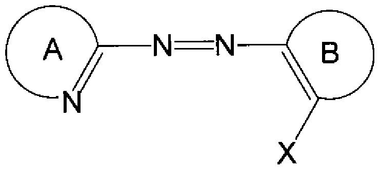
[0041] 一般式 (I)中、環 Aは、置換基を有してもよい芳香族複素環を表わす。例としては、 チアゾール、チアジアゾール、イミダゾール、トリァゾール、ピリジン、ピリミジン等が挙 げられる。中でもチアジアゾール、イミダゾール、ピリジンが好ましい。
[0042] 一般式 (I)中、 Xは、活性水素を有する基を表わす。例としては、スルホン酸、カル ボン酸、水酸基、スルホンアミド、カルボキシアミド等が挙げられる。中でも、スルホン アミド、力ノレボキシアミドが好ましい。
[0043] 一般式 (I)中、環 Bは、 Xの他に置換基を有してもよい芳香環又は芳香族複素環を 表わす。例としては、ベンゼン、ナフタレン、ピリジン、キノリン等が挙げられる。中でも 、ベンゼンが好ましい。また、置換基の例としてはァミノ基、アルキル基、アルコキシ基 、ハロゲン原子等が挙げられる。中でも、ァミノ基が好ましい。
[0044]

[0045] 一般式 (II)中、環 C及び環 Dは各々独立に、インドレニン環、ベンゾインドレニン環 、又はジベンゾインドレ-ン環を表わす。中でも、ベンゾインドレニン環が好ましい。
[0046] 一般式 (II)中、 Lは、モノメチン基又はトリメチン基を表わす。中でも、トリメチン基が 好ましい。
[0047] 一般式 (Π)中、 R1及び R2は各々独立に、置換基を有してもよいアルキル基を表わ す。例としては、メチル基、ェチル基、へキシル基等が挙げられる。中でも、メチル基 、ェチル基が好ましい。また、置換基の例としてはアルキル基、ァリール基、ハロゲン
原子、アルコキシ基、アミノ基等が挙げられる。中でも、アルキル基、アルコキシ基が 好ましい。
[0048] 尚、上記色素保持率の評価を行なうための「所定の耐光性試験」は、 ISO— 105— B02に示される Wool scale 5級の耐光性試験条件で行なうことが好ましい。
[0049] 以下で説明するように、力かる耐光性が十分でないァゾ系金属キレート色素を母体 色素とする光記録媒体において、本発明の効果の差がより明確となるのである。
[0050] 本発明が適用される光記録媒体において、記録層が、少なくとも、 Cu2+、 Fe2+、 C o2+の何れかを中心金属イオンとする金属キレート色素添加剤を含む。色素化合物 を配位子とし、更に、 Cu2+、 Fe2+、 Co2+を中心金属イオンとすることにより、従来の ニッケル錯体よりも、より強力な耐光性向上効果を得ることができるのである。これは 特に、 Fe2+、 Co2+は、 Ni2+よりも d電子が少ないことから、 Fe2+、 Co2+を中心金属ィ オンとする金属キレート色素の安定ィ匕エネルギーが大きいこと、また、吸収帯が Ni2+ を中心金属イオンとする金属キレート色素よりも長波長側に吸収ピークが存在するこ とに起因するものと考えられる。更に、それら中心金属イオンと配位子との組み合わ せを最適化することにより、より優れた耐光性向上効果を有する添加剤となりうるので ある。即ち、耐光性に劣る母体色素が吸収した光エネルギーを、母体色素よりも低い エネルギーレベルを有する添加剤がより効率よく quench或 、は失活すること〖こより、 母体色素の褪色が起こり難くなると考えられる等、添加剤の吸収波長や励起状態を 調整することにより、その添加剤の有する耐光性の向上効果をより高めることができる のである。
[0051] 具体的には、まず、上記中心金属イオンの差による吸収帯の波長の差については 、配位子場理論において説明できる場合がある。例えば、後述する [実施例]の [表 5 ]に示す通り、 Co2+を中心金属イオンとする場合には、吸光度の大きい吸収帯(主吸 収帯と呼ぶことがある。)が Ni2+よりも長波長側に存在することが多い。また、 Fe2+を 中心金属イオンとする場合には、 680nm以上の長波長側に、吸収帯が存在する。ま た、通常は波長 680nm以上に吸収を有さな 、ことが多 、Co2+を中心金属イオンと する場合に、実験群で例示するような特定の配位子を用いることにより、 680nm以上 の長波長側に吸収帯を有するァゾ系コバルトキレート色素添加剤を得ることができる
。力かるァゾ系コバルトキレート色素添加剤は、耐光性の向上効果にも優れている。
[0052] 特に、上記波長 680nm以上に吸収帯を有するもののうちで、配位子力 例えば以 下で例示するような構造式を有する化合物の場合には、添加剤が上記波長 680nm 以上の吸収帯にカ卩えて、波長 630nm以下の強い吸収極大を有する。このため、波 長 700nm以下の光で情報の記録再生が可能な多くの母体色素が有する波長 630η m以下の母体色素の吸収極大の吸収端との吸収の重なり、或いは、エネルギー準位 が近 、、母体色素の振電準位を介しての母体色素からのエネルギー移動が起こり易 くなり、母体色素の耐光性向上により効果的であると考えられる。
[0053] 即ち、本発明の添加剤としては、膜あるいは溶液の状態で、 400〜800nmの波長 範囲において、 630nm以下に一以上の吸収極大を有し、更に、 680nm以上にも一 以上の吸収極大を有するものが好まし 、。
換言すれば、本発明の添加剤としては、膜あるいは溶液の状態で、 400ηπ!〜 800 nmの波長範囲に着目した場合に、 630nm以下の短波長側の領域(即ち、 400nm 〜630nmの波長範囲)と、 680nm以上の長波長側の領域(即ち、 680nm〜800n mの波長範囲)とに、それぞれ一以上の吸収極大を有するものが好ましい。
[0054] 特に、本発明の添加剤としては、 680nm以上の長波長側の吸収帯の短波長側の 吸収端と、 630nm以下の短波長側の吸収帯(主吸収帯)の長波長側の吸収端とが 重なりを持つ、通常の有機色素としては好まれない傾向の吸収スペクトルを有するも のが、耐光性向上用の添加剤としてより好ましい (例えば後述の図 12 (a) , (b)参照)
[0055] 尚、本発明の耐光性向上の効果は、母体色素がシァニン系色素である場合よりも、 ァゾ系金属キレート色素である場合において、より差が明確となった。即ち、波長 70 Onm以下の光による記録用のシァニン系色素は、ァゾ系金属キレート色素よりは、遷 移金属中心イオンによる quench効果或いは失活効果が上がり易いのである。このこ とから、ァゾ系金属キレート色素には、特に耐光性が向上し難い要因があるものと考 えられる。従って、耐光性試験におけるァゾ系金属キレート色素の劣化のメカニズム には、シァニン系色素の劣化のメカニズムとは異なる要素が存在する可能性がある。
[0056] 尚、より耐光性向上効果が現れ難いァゾ系キレート色素を母体色素とする場合には
、本発明の添加剤を添加することにより、添加しない場合と比べて耐光性が 20%以 上向上すれば、単なる吸収のマスキング効果を超える、明確な耐光性向上効果であ ることがいえると考えられる。中でも、本発明の添加剤を添加することにより、添加しな い場合と比べて耐光性が 30%以上増加することがより好ましぐ 40%以上増加する ことが更に好ましい。
[0057] 一方、耐光性向上効果が現れ易いシァニン系色素などの π— π *遷移を有する色 素に対しては、本発明の添加剤を添加することにより 60%以上の耐光性の増加があ れば、十分有効であると考えられる。
[0058] 以上説明したように、ァゾ系金属キレート色素には、シァニン系色素よりもより強力 な耐光性向上用の添加剤が好まし 、のである。
[0059] 上述のように、耐光性向上の効果は、添加剤の中心金属イオンにより異なる力 添 加剤自体の耐光性は、添加剤の中心金属イオンによる差が見られない (例えば後述 する図 11参照)。このことから、 Fe2+、 Co2+又は Cu2+を中心金属イオンとする本発 明の添加剤には、従来知られてきたように、単に中心金属イオンを変えることにより添 加剤自体の耐光性を向上させたり、耐光性の悪い色素に耐光性の良い色素を吸収 マスキング用に添加して、耐光性を向上させたりすることとは異なる、格段の効果を示 唆するものである。本発明の添加剤によって得られるこの格段の効果は、中でも中心 金属イオンが Fe2+又は Co2+である場合、特に中心金属イオンが Fe2+の場合又は中 心金属イオン Co2+と特定の配位子との組み合わせの場合に、より顕著となる。
[0060] 更に、先に説明した理由により、本発明の添加剤を有する記録層が、 400〜800n mの波長範囲において、 630nm以下に一以上の吸収極大を有し、更に、 680nm以 上にも一以上の吸収極大を有するものが好ま 、。
換言すれば、本発明の添加剤を有する記録層は、 400nn!〜 800nmの波長範囲 に着目した場合に、 630nm以下の短波長側の領域(即ち、 400nm〜630nmの波 長範囲)に一以上の吸収極大を有するとともに、更に、 680nm以上の長波長側の領 域(即ち、 680ηπ!〜 800nmの波長範囲)にも一以上の吸収極大を有することが好ま しい。
[0061] 特に、添加剤そのもの力 記録光波長近傍に、モル吸光係数 ε力 ¾ X 104、好まし
くは 5 X 10⁴を超えるような、非常に吸光度が大きい主吸収帯の吸収端を有する場合 、更に、波長 680nm以上の高工ネルギー側の吸収端が記録光波長近傍にも有する 場合には、記録層の母体色素が吸収した励起エネルギーが、前記吸収端を通して、 効率よく添加剤の励起バンドから失活過程に伝播されるために、より大きな quench 効果或いは失活効果があり、耐光性向上効果が大きくなると考えられる。更に、添カロ 剤分子内での波長 630nm以下の吸収帯の吸収端と波長 680nm以上の吸収帯の 吸収端との重なりが大きいほど、 2つの吸収帯間でのエネルギー移動が起こり易くな るため、より耐光性向上の効果が生じると考えられる。従って、例えば、従来知られて きたニッケル等のジチオール金属錯体にお 、ては、可視部には弱 、吸収しかな 、の で、本発明の添加剤ほどの効果がないと考えられる。以上のように、本発明における 「金属キレート色素」は、力かる大きな吸収を、少なくとも可視部に有する金属キレート 色素をいうのである。
[0062] また、従来は、記録光波長近傍の吸収帯と lOOOnm近傍の長波長側の吸収帯とを
、別の化合物で担う(添加する)、或いは、塩を形成して、異分子間よりはやや近い部 分でエネルギー移動を起こさせることが知られてきた。それに対し、本発明では、より 好ましくは、 1つの化合物が強い吸収帯を上記 2つの領域に有するのである。 1つの 化合物内にそのような吸収帯を併せ持つことにより、吸収した記録再生光或いは耐 光性試験光のより効率良 、エネルギー移動、そして quench効果或いは失活効果が 可能となり、より大きな耐光性向上効果が得られると考えられる。その吸収帯は吸光 度が大きいほど有効であり、力かる大きな吸光度を得るために、配位子の選択がボイ ントとなる。もちろん、上記吸収帯の波長には、配位子と中心金属イオンとの組み合 わせが関与すると考えられる。
[0063] また、塩を形成する方法に比べて、添加剤を用いる本発明の方法は、添加剤の添 加量を自由に設定できるため、記録特性や記録層の膜質の劣化を防ぐことが可能と なり易い。
[0064] かかる、より好ましい添加剤として、より具体的には、一部のァゾ色素化合物を配位 子として有する Co2+を中心金属イオンとするァゾ系金属キレート色素力、 Fe2+を中 心金属イオンとするァゾ系金属キレート色素が該当する。
[0065] なお、上記好ましいァゾ系金属キレート色素添加剤である、一分子内に波長 630η m以下の吸収極大と波長 680nm以上の長波長側の吸収極大とを有するァゾ系金属 キレート色素においては、その吸収スペクトル力 溶液状態と塗布膜の状態とで吸収 ピーク波長に 10nm未満の小さな差しか見られない。これも耐光性向上用の添加剤 としての安定な添加効果と関連すると考えられる。
[0066] 本発明の添加剤の配位子を構成するァゾ系色素化合物の例として、具体的には、 以下の化合物が挙げられる。
[0067] [化 7]

[0068] [化 8]

[0069] [化 9]


[0071] [化 11]

[0072] [化 12]

[0073] [化 13]

[0074] [化 14]

[0075] [化 15]

[0076] [化 16]

2 3
CF基力 活性水素の脱離によって N_ (SO CF )基又は N—COCF基となり、
3 2 3 3 中心金属イオンに配位する。なお、力かるァゾ系色素化合物は、母体色素の配位子
としても好ましい。
[0078] 力かるァゾ系色素化合物を配位子として有する添加剤が好ましい理由は、可視部 に非常に強い吸収帯が得られるからであると考えている。これは、先に述べたように、 母体色素が添加剤に、より効率よく光エネルギーを伝播することができるからである。
[0079] 同様の理由により、母体色素とエネルギー移動が生じ易い構造を有する添加剤の 配位子も好ましい。力かる意味においては、母体色素も上記添加剤の配位子を有す ることが好ま U、場合がある。
[0080] 一方、本発明は、下記一般式 (III) , (IV)で示される化合物を配位子として有するこ とを特徴とする、光記録媒体の記録層の添加剤として捉えられる。
即ち、本発明における耐光性向上用の添加剤としては、 1つは、下記一般式 (III)で 表わされるァゾィ匕合物カゝら Xの有する活性水素が脱離した配位子が 2つと、 Fe2+とか ら形成されるァゾ系鉄キレート色素 (これを「本発明のァゾ系鉄キレート色素」と!、う場 合がある。)からなる、ァゾ系金属キレート色素添加剤である。
[0081] [化 17]

[0082] 一般式 (III)中、環 Eは、置換基を有してもよい芳香族複素環を表わす。例として、 チアゾール、チアジアゾール、イミダゾール、トリァゾール、ピリジン、ピリミジン等が挙 げられる。中でも、チアジアゾール、イミダゾール、ピリジンが好ましい。置換基を有す る場合、その例としては、アルキル基、ァリール基、ハロゲン原子、エステル基、シァノ 基、ニトロ基、アルコキシ基、アルキルチオ基等が挙げられる。中でも、アルキル基、 エステル基、シァノ基が好ましい。
[0083] 一般式 (III)中、 R3及び R4は各々独立に、置換基を有してもよいアルキル基を表わ す。例としては、メチル基、ェチル基、イソブチル基等が挙げられる。中でも、ェチル 基、イソブチル基が好ましい。置換基を有する場合、その例としては、ァリール基、ァ ルコキシ基、エステル基、ハロゲン原子等が挙げられる。
[0084] なお、一般式 (III)にお 、て、 R3と R4同士が結合して環を形成して 、てもよ 、。例と しては、アジリジン、ァゼチジン、ピロリジン、ピぺリジン、ァゼパン、モルフォリン等が 挙げられる。中でも、ピロリジン、ピぺリジンが好ましい。
[0085] また、一般式 (III)にお 、て、 R3及び R4の一方又は両方がベンゼン環と結合して、 ベンゼン環に縮合する 4〜7員環を形成してもよい。例としては、インドリン、テトラヒド 口キノリン、ベンズァゼピン、力ルバゾール等が挙げられる。中でも、インドリン、テトラ ヒドロキノリンが好ましい。
[0086] 一般式 (III)中、 Xは、活性水素を有する有機基を表わす。例えば、スルホンアミド 基、カルボキシアミド基、スルホン酸基、カルボン酸基、水酸基等が挙げられる。カル ボキシアミド基ゃスルホンアミド基が好ましい。中でも、 -NHSO CF等のスルホン
2 3
アミド基は、鉄錯体が安定して得られるため、特に好ましい。
[0087] なお、上記一般式 (III)にお 、て、 2つの配位子の環 E、 X、 R3及び R4は、何れも、 互いに同じであってもよぐ異なっていてもよい。
[0088] 上記一般式 (III)で表わされる配位子の 1分子あたりの分子量は、通常 100以上、 好ましくは 300以上、また、通常 1000以下、好ましくは 600以下の範囲である。配位 子の分子量が小さ過ぎると、吸収波長や溶解性などの調整範囲が狭くなる可能性が あるという理由で好ましくなぐまた、配位子の分子量が大き過ぎると、グラム吸光係 数が小さくなり、光学特性が悪ィ匕するという理由でやはり好ましくない。
[0089] 特に、上述のァゾ系鉄キレート色素からなるァゾ系金属キレート色素添加剤の場合 には、その配位子としてはニッケル錯体などの記録色素で記録特性の良 ヽ配位子を 用いると、より好ましい。具体的には、先に述べたような「本発明の添加剤の配位子を 構成するァゾ系色素化合物」の例として挙げたものが使用できる。し力しながら、耐光 性を向上させる添加剤としては、記録特性に特に関与する必要は無い。
[0090] 本発明における耐光性向上用の添加剤として、もう 1つは、下記一般式 (IV)で表わ されるァゾ化合物から Xの有する活性水素が脱離した配位子が 2つと、 Co2+とから形 成され、膜或いは溶液の状態で、 400nm〜630nmの波長範囲及び 680nm〜800 nmの波長範囲にそれぞれ一以上の吸収極大を有する、ァゾ系金属キレート色素添 加剤である。
[0091] [化 18]

[0092] なお、本ァゾ系コバルトキレート色素添加剤の「680nm以上の吸収極大」には、明 確な吸収極大の他に、吸収帯の吸収端に別の吸収帯が含まれていると認識できる、 いわゆる「吸収肩」も含まれる。
[0093] 一般式 (IV)中、環 Eは、置換基 (アルキル基、ァリール基、ハロゲン原子、エステル 基、シァノ基、ニトロ基、アルコキシ基、アルキルチオ基等。中でも、アルキル基、エス テル基、シァノ基が好ましい。)を有してもよい芳香族複素環を表わす。
[0094] 一般式 (IV)中、 R3及び R4は各々独立に、置換基を有してもよ!、アルキル基を表わ す。例としては、メチル基、ェチル基、イソブチル基等が挙げられる。中でも、ェチル 基、イソブチル基が好ましい。置換基を有する場合、その例としては、ァリール基、ァ ルコキシ基、エステル基、ハロゲン原子等が挙げられる。
[0095] なお、一般式 (IV)にお 、て、 R3と R4同士が結合して環を形成して 、てもよ 、。例と しては、アジリジン、ァゼチジン、ピロリジン、ピぺリジン、ァゼパン、モルフォリン等が 挙げられる。中でも、ピロリジン、ピぺリジンが好ましい。
[0096] また、一般式 (IV)にお 、て、 R3及び R4の一方又は両方がベンゼン環と結合して、 ベンゼン環に縮合する 4〜7員環を形成してもよい。例としては、インドリン、テトラヒド 口キノリン、ベンズァゼピン、力ルバゾール等が挙げられる。中でも、インドリン、テトラ ヒドロキノリンが好ましい。
[0097] 一般式 (IV)中、 Xは、活性水素を有する有機基を表わす。例えば、スルホンアミド 基、カルボキシアミド基、スルホン酸基、カルボン酸基、水酸基等が挙げられる。カル ボキシアミド基ゃスルホンアミド基が好ましい。中でも、 -NHSO CF等のスルホン
2 3
アミド基は、鉄錯体が安定して得られるため、特に好ましい。
[0098] なお、一般式(IV)にお!/、て、 2つの配位子の環 E、 X、 R3及び R4は、何れも、互!ヽ に同じであってもよぐ異なっていてもよい。
[0099] 上記一般式 (IV)で表わされる配位子の分子量は、通常 100以上、好ましくは 300 以上、また、通常 1000以下、好ましくは 600以下の範囲である。配位子の分子量が 小さ過ぎると、吸収波長や溶解性などの調整範囲が狭くなる可能性があるという理由 で好ましくなぐまた、配位子の分子量が大き過ぎると、グラム吸光係数力 、さくなり、 光学特性が悪ィ匕するという理由でやはり好ましくない。
[0100] なお、中心金属イオンが Co2+であるァゾ系金属キレート色素添加剤は、理由は明 らかではないが、 680nm以上の吸収極大の有無力 配位子によって分かたれる場 合がある。
好まし ヽ配位子の例としては、下記のものが挙げられる。
[0101] [化 19]

[0103] 上記のように、記録層が本発明の添加剤を含み、記録層単層での紫外'可視吸収 スペクトル(400nm〜800nmの波長範囲)において、波長 630nm以下の吸収の他 に、波長 680nm以上にも吸収極大を有することが好ましい。これは、すでに説明した ように、例えば Fe2+を中心金属イオンとする金属キレート色素において顕著な吸収 極大を有する添加剤を、記録層が適量含むことを意味する。
[0104] 添加剤を含有する記録層の吸収スペクトルから、添加剤自体の波長 680nm以上 の吸収帯がどの程度強い吸収であるか、そして、そのような添加剤をどの程度の量添 加するかを判断するには、吸収極大波長での吸光度を b、その吸収帯が無いと仮定 した場合における吸収スペクトルのベースラインの吸光度を aとして、 bZaの値を求め ればよい。
[0105] ここで、添加剤を含有する記録層の吸収スペクトル力 bZa値を求めるための手法 について、図 7 (a) , (b)を用いて説明する。
[0106] 波長 680nm以上の領域に吸収極大(ピーク)が存在する場合にお!、て、図 7 (a)に 示すように、記録層の、波長 630nm以下の吸収帯よりも波長 680nm以上の長波長 側の吸収帯の方が吸光度がはるかに低ぐ或いは、両者の吸収帯の吸収端の重なり がそれほど大きくなぐベースラインがなだらかに減衰している場合には、ピークの両 側の吸収スペクトルに沿ってペースラインの外揷線(図中の点線)を作成することによ り、ベースラインを補間することができる。
[0107] 一方、図 7 (b)に示すように、ピークの高波長側の吸光度が低波長側の吸光度と同 じかそれより高い場合には、上述の手法だとベースラインを補完することは困難であ る。よってこの場合は、ピークの低波長側の立ち上がり部分の吸光度を求め、吸光度 力 の値で一定となる直線(図中の点線)を作成し、これをペースラインの外挿線とす る。
[0108] なお、図 7 (b)に示すような吸収スペクトルが現われる場合としては、例えば、添カロ
剤の波長 630nm以下の吸収極大に対して、波長 680nm以上の長波長側の吸収極 大が極端に強!ヽ場合が挙げられる。
[0109] 本発明においては、前述のエネルギー移動がより効率的に行える図 7 (a)の方が図 7 (b)よりも好ま U、と考えられる。
[0110] 以上のことから、 bZa> 1の場合、つまり、波長 630nm以下の吸収極大の他に、 6 80nm以上の長波長側に、弱いながらも吸収帯があると認識できる場合には、波長 7 OOnm以下の光が照射されることにより情報の記録又は再生が可能な有機色素を含 有する記録層に対して、より顕著な耐光性の向上が見られるといえる。明確な添加効 果を得るためには、 bZaは、 1. 05以上がより好ましぐ 1. 1以上が更に好ましい。
[0111] 尚、 bZaは、 1. 5以下が好ましい。それは先に述べたように、本発明の添加剤が必 ずしも記録特性を重視したものではな 、ため、適当な添加量が好ま 、からである。
[0112] 尚、本発明における Cu2+、 Fe2+、 Co2+を中心金属イオンとする添加剤の検出は、 例えば、以下の(1)〜 (4)の方法で行なうことができる。
[0113] ,方法(1) :
記録層を有する光ディスクを切り出し、記録層を適切な有機溶媒に溶解して得た溶 液に対して、イオンクロマト法を行なう。その場合には、ポストカラムにより発色剤を混 合し、イオンを分離して検出する。より詳しくは、発色剤で各イオンの吸収領域を広げ 、それぞれのイオンをカラムで分離し、各イオンを、ピークの生じる時間として検出し、 同時にその強度も検出できる。
[0114] 一方、以下の(2)〜 (4)の方法は、固層(膜)サンプル、或いは、固体 (色素粉末) サンプルを用いて行なうことができる。即ち、記録層やディスクより抽出した色素、或 いは、色素そのものを対象として行なうことができる。
[0115] ,方法(2) (XAFS法):
上記サンプルの X線吸収スペクトルで、吸収端よりも高エネルギー側約 30eV〜lK eVにわたる領域で、各イオンがそれぞれ固有の波長で X線吸収し励起されるので、 各イオンを識別できる。
[0116] ,方法(3) (XPS法):
上記サンプルに X線を照射すると、各イオンにより、スペクトルの運動エネルギー分
布が異なるため、各イオンを識別できる。
[0117] ,方法 (4) (メスバウワー法):
鉄イオンのみの検出に有効な方法である。ドップラー効果により、共鳴吸収の位置 や幅、或いはドップラー速度を横軸にした吸収曲線が得られる。鉄イオンに対しては
、 2価、 3価はスペクトルが異なるため、それらの識別ができる。
[0118] その他には、例えば、 Trends in Analytical Chemistry, 24(3), 2005, pp.192- 198に 記載の方法により各イオンの識別ができる。
[0119] [II.本発明の実施の形態]
続いて、本発明の実施の形態について、図 1 (a) , (b)、図 2 (a) , (b)、図 3 (a) , (b
)を用いて説明する。なお、図 1 (a) , (b)、図 2 (a) , (b)、図 3 (a) , (b)は各々、本発 明の実施の形態に係る光記録媒体 100〜600の層構成の例を模式的に表わす部 分断面図である。
[0120] 尚、以下の記載では説明の便宜上、図 1 (a) , (b)、図 2 (a) , (b)、図 3 (a) , (b)の 各図において、図の上方及び下方をそれぞれ光記録媒体 100〜600の上方及び下 方とし、これらの方向に対応する、光記録媒体 100〜600を構成する各層の各面を、 それぞれ各層の上面及び下面とする。
[0121] 本発明の光記録媒体は少なくとも、基板と、記録層と、反射層とを備えて構成される 。そして上述の様に、記録層が、 700nm以下の光が照射されることにより情報の記 録又は再生が可能な有機色素と、 Cu2+、 Fe2+、 Co2+の何れかを中心金属イオンと するァゾ系金属キレート色素である添加剤 (本発明の添加剤)とを含有する。尚、必 要に応じて、下引き層、保護層等、その他の各種の層を設けてもよい。
[0122] まず、本発明の第 1実施形態について説明する。
図 1 (a)は、本発明の第 1実施形態に係る光記録媒体の層構成を模式的に示す図 である。図 1 (a)に示される光記録媒体 100は、光透過性材料からなる基板 101と、 基板 101上に設けられた記録層 102と、記録層 102上に順に積層された反射層 103 及び保護層 104とを備えている。そして、この光記録媒体 100は、基板 101側から照 射されるレーザー光 110により、情報の記録 '再生が行なわれる。
以下、これら各層について順に説明する。
[0123] 基板 101は、基本的に記録光及び再生光の波長において透明な材料であれば、 様々な材料を使用することができる。具体的には、例えば、アクリル系榭脂、メタタリ ル系榭脂、ポリカーボネート榭脂、ポリオレフイン系榭脂(特に、非晶質ポリオレフイン )、ポリエステル系榭脂、ポリスチレン榭脂、エポキシ榭脂等の榭脂;ガラスが挙げら れる。また、ガラス上に光硬化性榭脂等の放射線硬化性榭脂からなる榭脂層を設け た構造が挙げられる。中でも、高生産性、コスト、耐吸湿性等の観点力 は、射出成 型法にて使用されるポリカーボネート榭脂、耐薬品性及び耐吸湿性等の観点からは 、非晶質ポリオレフインが好ましい。更に、高速応答等の観点からは、ガラスが好まし い。
[0124] 榭脂製の基板 101を使用した場合、又は、記録層と接する側 (上側)に榭脂層を設 けた基板 101を使用した場合には、上面に、記録再生光の案内溝やピットを形成し てもよい。案内溝の形状としては、光記録媒体 100の中心を基準とした同心円状の 形状やスパイラル状の形状が挙げられる。スパイラル状の案内溝を形成する場合に は、溝ピッチが 0. 2 μ m〜0. 8 μ m程度であることが好ましい。
[0125] 記録層 102は、基板 101の上側に直接、又は必要に応じて基板 1上に設けた下引 き層等の上側に形成され、 700nm以下の光が照射されることにより情報の記録又は 再生が可能な有機色素 (母体色素)と、少なくとも、 Cu2+、 Fe2+、 Co2+の何れかを中 心金属イオンとするァゾ系金属キレート色素である添加剤 (本発明の添加剤)とを含 有する。母体色素及び本発明の添加剤は何れも、一種を単独で用いてもよぐ二種 以上を任意の組み合わせ及び比率で併用してもょ 、。
[0126] 記録層 102には、母体色素及び本発明の添加剤以外の色素として、必要に応じて ベンゾフエノン系色素、フタロシアニン系色素、ナフタロシアニン系色素、ァゾ系金属 キレート色素、スクァリリウム系色素、トリアリールメタン系色素、メロシアニン系色素、 ァズレニウム系色素、ナフトキノン系色素、アントラキノン系色素、インドフエノール系 色素、キサンテン系色素、ォキサジン系色素、ピリリウム系色素等の有機色素や、更 に、必要に応じて、バインダー、レべリング剤、消泡剤等を併用することもできる。これ らの成分は、何れか一種を単独で用いてもよぐ二種以上を任意の組み合わせ及び 比率で併用してもよい。但し、これらの成分の使用量は、本発明の目的である高速或
いは高密度記録の特性を損なうことがな 、範囲内に抑えるようにする。
[0127] 記録層 102の成膜方法としては、真空蒸着法、スパッタリング法、ドクターブレード 法、キャスト法、スピンコート法、浸漬法等、一般に行なわれている様々な薄膜形成 法が挙げられる。量産性やコストの観点からは、スピンコート法が好ましぐ均一な厚 みの記録層 102が得られるという観点からは、塗布法よりも真空蒸着法等の方が好ま しい。スピンコート法による成膜の場合、回転数は 500rpm〜15000rpmが好ましい 。また、場合によっては、スピンコートの後に、加熱する、溶媒蒸気にあてる等の処理 を施してもよい。
[0128] ドクターブレード法、キャスト法、スピンコート法、浸漬法等の塗布法により記録層 10 2を形成する場合には、母体色素及び本発明の添加剤、並びに必要に応じて用いら れる他の成分を溶媒に溶解させて塗布液を作製し、これを基板 101に塗布すること により記録層 102を形成する。塗布液の作製に使用する塗布溶媒は、基板 101を侵 食せず、分光光度計で吸収が検出可能な濃度の溶液を作製できうる程度に、母体 色素及び本発明の添加剤に対して溶解性を示す溶媒であれば、その種類は特に限 定されない。具体的には、例えばジアセトンアルコール、 3—ヒドロキシー3—メチル 2—ブタノン等のケトンアルコール系溶媒;メチルセ口ソルブ、ェチルセ口ソルブ等 のセロソルブ系溶媒; n—へキサン、 n オクタン等の鎖状炭化水素系溶媒;シクロへ キサン、メチルシクロへキサン、ェチルシクロへキサン、ジメチルシクロへキサン、 n— ブチルシクロへキサン、 tert—ブチルシクロへキサン、シクロオクタン等の環状炭化水 素系溶媒;テトラフルォロプロパノール、ォクタフルォロペンタノール、へキサフルォロ ブタノール等のパーフルォロアルキルアルコール系溶媒;乳酸メチル、乳酸ェチル、 2—ヒドロキシイソ酪酸メチル等のヒドロキシカルボン酸エステル系溶媒等が挙げられ る。
[0129] 一方、真空蒸着法を用いる場合には、例えば、必要に応じて他の色素や各種添カロ 剤等の記録層成分を、真空容器内に設置されたるつぼに入れ、この真空容器内を 適当な真空ポンプで 10一2〜 10_5Pa程度にまで排気した後、るつぼを加熱して記録 層成分を蒸発させ、るつぼと向き合って置かれた基板上に蒸着させることによって、 記録層 102を形成する。
[0130] 記録層 102の膜厚は、記録方法等により適した膜厚が異なる為、特に限定するもの ではないが、記録を可能とするためにはある程度の膜厚が必要とされるため、通常 1 nm以上、好ましくは 5nm以上である。但し、あまり厚すぎても記録が良好に行なえな くなるおそれがあるため、通常 300nm以下、好ましくは 200nm以下、より好ましくは 1 OOnm以下である。
[0131] また、記録層 102は、記録再生光波長における消衰係数 (複素屈折率の虚部) kが 通常 0. 01以上、 0. 6以下であることが好ましい。また、記録再生光波長における屈 折率 (複素屈折率の実部) nが通常 0. 5以上、 3以下であることが好ましい。
[0132] 反射層 103は、記録層 102の上に形成されている。反射層 103の膜厚は、好ましく は 30nm以上、より好ましくは 50nm以上、また、好ましくは 300nm以下、より好ましく は 200nm以下の範囲である。反射層 103の材料としては、再生光の波長において 十分高い反射率を有する材料、例えば、 Au、 Al、 Ag、 Cu、 Ti、 Cr、 Ni、 Pt、 Ta、 P d等の金属を、単独或いは合金にして用いることができる。これらの中でも Au、 Al、 A gは反射率が高ぐ反射層 103の材料として適して 、る。
[0133] また、これらの金属を主成分とした上で、加えて他の材料を含有させてもょ 、。ここ で「主成分」とは、含有率が 50%以上のものをいう。主成分以外の他の材料としては 、例えば、 Mg、 Se、 Hf、 V、 Nb、 Ru、 W、 Mn、 Re、 Fe、 Co、 Rh、 Ir、 Cu、 Zn、 Cd、 Ga、 In、 Si、 Ge、 Te、 Pb、 Po、 Sn、 Bi、 Ta、 Ti、 Pt、 Pd、 Nd等の金属及び半金属 を挙げることができる。中でも Agを主成分とするものは、コストが安い点、高反射率が 出易い点、後述する印刷受容層を設けた場合に地色が白く美しいものが得られる点 等から、特に好ましい。例えば、 Agを主成分として、更に Au、 Pd、 Pt、 Cu、及び Nd 力 選ばれる一種以上を通常 0. 1原子%以上、 5原子%以下程度含有させた合金 は、高反射率、高耐久性、高感度且つ低コストであり好ましい。具体的には、例えば 、 AgPdCu合金、 AgCuAu合金、 AgCuAuNd合金、 AgCuNd合金等である。金属 以外の材料としては、低屈折率薄膜と高屈折率薄膜を交互に積み重ねて多層膜を 形成し、これを反射層 103として用いることも可能である。
[0134] 反射層 103を形成する方法としては、例えば、スパッタリング法、イオンプレーティン グ法、化学蒸着法、真空蒸着法等が挙げられる。また、基板 101の上や反射層 103
の下に、反射率の向上、記録特性の改善、密着性の向上等のために、公知の無機 系又は有機系の中間層、接着層を設けることもできる。
[0135] 保護層 104は、反射層 103の上に形成される。保護層 104の材料は、反射層 103 を外力から保護することが可能なものであれば、特に限定されない。具体的に、有機 物質の材料の例としては、熱可塑性榭脂、熱硬化性榭脂、電子線硬化性榭脂、 UV 硬化性榭脂等を挙げることができる。また、無機物質の例としては、酸化ケィ素、窒化 ケィ素、フッ化マグネシウム(MgF )、二酸化スズ(SnO )等が挙げられる。これらの
2 2
材料は、何れか一種を単独で用いても、複数種を混合して用いてもよい。
[0136] 熱可塑性榭脂、熱硬化性榭脂等を用いる場合は、適当な溶剤に溶解して調製した 塗布液を反射層 103の上に塗布して乾燥させれば、保護層 104を形成することがで きる。
また、 UV硬化性榭脂を用いる場合は、そのまま反射層 103の上に塗布するカゝ、又 は適当な溶剤に溶解して調製した塗布液を反射層 103の上に塗布し、 UV光を照射 して硬化させることによって、保護層 104を形成することができる。なお、 UV硬化性 榭脂としては、例えば、ウレタンアタリレート、エポキシアタリレート、ポリエステルアタリ レート等のアタリレート系榭脂を用いることができる。
[0137] 保護層 104の形成方法としては、記録層 102と同様に、スピンコート法やキャスト法 等の塗布法や、スパッタリング法や化学蒸着法等の方法が用いられるが、中でもスピ ンコート法が好ましい。
[0138] 保護層 104の膜厚は、その保護機能を果たすためにはある程度の厚みが必要とさ れるため、通常 0. 1 μ m以上、好ましくは 3 μ m以上である。但し、あまり厚すぎると、 効果が変わらないだけでなぐ保護層 104の形成に時間が力かったりコストが高くな る虞があるので、通常 100 μ m以下、好ましくは 30 μ m以下である。
なお、保護層 104は、単層として形成してもよぐ多層として形成してもよい。
[0139] 次に、本発明の第 2実施形態について説明する。
図 1 (b)は、本発明の第 2実施形態に係る光記録媒体の層構成を模式的に示す図 である。図 1 (b)に示される光記録媒体 200は、光透過性材料カゝらなる基板 201と、 基板 201上に設けられた反射層 202と、反射層 202上に順に積層された記録層 203
及び保護層 204とを備えている。そして、この光記録媒体 200は、保護層 204側から 照射されるレーザー光 210により、情報の記録 '再生が行なわれる。
以下、これら各層について順に説明する。
[0140] 基板 201は、第 1実施形態における基板 101と基本的に同様であるが、必ずしも透 明である必要はない。従って、基板 101について前述した材料以外にも、不透明な 榭脂、セラミック、金属 (合金を含む)等を用いることができる。
[0141] 反射層 202及び記録層 203は、それぞれ第 1実施形態における反射層 103及び 記録層 102と同様である。
[0142] 保護層 204は、 50 μ m〜100 μ mの厚さのフィルム又はシート状のものを接着剤に よって貼り合わせてもよぐまた、第 1実施形態における保護層 104と同様の材料を用 い、成膜用の塗液を塗布し硬化又は乾燥する工程を繰り返して積層することにより形 成してもよい。保護層 204は、ピックアップの焦点深度等を考慮して光学的に許容さ れる厚み範囲とするのが好ましぐ通常は全体としての膜厚が 100 m± 3 m程度 である。
[0143] ところで、光記録媒体 100, 200の記録密度を上げるための一つの手段として、対 物レンズの開口数を上げることがある。これにより情報記録面に集光される光スポット を微小化できる。し力しながら、対物レンズの開口数を上げると、記録'再生を行なう ためにレーザー光を照射した際に、光記録媒体 100, 200の反り等に起因する光ス ポットの収差が大きくなり易いため、良好な記録再生信号が安定して得られない場合 がある。
[0144] このような収差は、レーザー光が透過する透明な基板 101や保護層 204の膜厚が 厚いほど大きくなり易いので、収差を小さくするためには基板 101や保護層 204をで きるだけ薄くするのが好ましい。但し、通常、基板 101は光記録媒体 100の強度を確 保するためにある程度の厚みを要するので、この場合、光記録媒体 200の層構成( 基板 201、反射層 202、記録層 203、保護層 204からなる基本的層構成)を採用す るのが好ましい。光記録媒体 100の基板 101を薄くするのに比べると、光記録媒体 2 00の保護層 204は薄くし易いため、高密度記録媒体には、光記録媒体 200を用い ることが好ましい。
[0145] 但し、光記録媒体 100の層構成 (基板 101、記録層 102、反射層 103、保護層 104 力 なる基本的層構成)であっても、記録 ·再生用レーザー光が通過する透明な基板 101の厚さを 50 μ m〜300 μ m程度にまで薄くすることにより、収差を小さくして使用 でさるよう〖こなる。
[0146] 続いて、本発明の第 3〜第 6実施形態について説明する。
図 2 (a)は、本発明の第 3実施形態に係る光記録媒体の層構成を模式的に示す図 である。図 2 (a)に示される光記録媒体 300は、基板(1) 301と、記録層(1) 302と、 反射層(1) 303と、保護層(1) 304と、接着層 305と、保護層(2) 306と、反射層(2) 307と、記録層(2) 308と、基板(2) 309とがこの順に積層された層構成を有する。こ の光記録媒体 300では、基板(2) 309側からレーザー光 310を照射することにより、 記録層(1) 302において、また、基板(1) 301側からレーザー光 311を照射すること により、記録層(2) 308において、それぞれ情報の記録 ·再生が行なわれる。
[0147] このような光記録媒体 300は、基板(1) 301、記録層(1) 302、反射層(1) 303、保 護層(1) 304をこの順に積層した貼り合わせ用ディスク 312と、基板(2) 309、記録層 (2) 308、反射層(2) 307、保護層(2) 306をこの順に積層した貼り合わせ用ディスク 313とを、保護層(1) 304及び保護層(2) 306を対向させて接着層 305で貼り合わせ ること〖こより構成される。
[0148] 上述の光記録媒体 300の各層のうち、基板(1) 301及び基板(2) 309は、第 1実施 形態における基板 101と基本的に同様である。
また、記録層 (1) 302及び記録層 (2) 308は、第 1実施形態における記録層 102と 基本的に同様である。
また、反射層(1) 303及び反射層(2) 307は、第 1実施形態における反射層 104と 基本的に同様である。
また、保護層(1) 304及び保護層(2) 306は、第 2実施形態における保護層 204と 基本的に同様である。
また、接着層 305の材料としては、貼り合わせ用ディスク 312の保護層(1) 304と貝占 り合わせ用ディスク 313の保護層(2) 306とを接着することが出来る透明な材料であ れば、任意の材料を用いることが可能である。具体的には、第 1実施形態における保
護層 104と同様の材料や、第 2実施形態における保護層 204と同様の材料を用いる ことができる。
[0149] 図 2 (b)は、本発明の第 4実施形態に係る光記録媒体の層構成を模式的に示す図 である。図 2 (b)に示される光記録媒体 400は、基板(1) 401と、反射層(1) 402と、 保護層(1) 403と、接着層 404と、保護層(2) 405と、反射層(2) 406と、記録層 407 と、基板 (2) 408とが順に積層された層構成を有する。この光記録媒体 400は、基板 (2) 408側力もレーザー光 410を照射することにより、記録層 207で情報の記録 '再 生が行なわれる。
[0150] この光記録媒体 400は、基板(1) 401、反射層(1) 402、保護層(1) 403をこの順 に積層したダミーディスク 411と、基板(2) 408、記録層 407、反射層(2) 406、保護 層(2) 405をこの順に積層した貼り合わせ用ディスク 412とを、保護層(1) 403及び 保護層(2) 405を対向させて接着層 404で貼り合わせることにより構成される。
また、保護層(1)及び保護層(2)を省略し、反射層(1) 402と反射層(2) 406とを対 向させて接着層 404で貼り合わせてもよ 、。
[0151] 上述の光記録媒体 400の各層のうち、基板(1) 401及び基板(2) 408は、第 1実施 形態における基板 101と、基本的に同様である。但し、基板(1) 401は必ずしも透明 である必要は無いため、第 2実施形態における基板 201と同様の材料も使用できる。 また、基板(1) 401には記録再生光の案内溝やピットを形成する必要は無 ヽ。
また、反射層(1) 402及び反射層(2) 406は、第 1実施形態における反射層 104と 基本的に同様である。
また、保護層(1) 403及び保護層(2) 405は、第 2実施形態における保護層 204と 基本的に同様である。
また、接着層 404は、第 3実施形態における接着層 305と基本的に同様である。 また、記録層 407は、第 1実施形態における記録層 102と基本的に同様である。
[0152] 図 3 (a)は、本発明の第 5実施形態に係る光記録媒体の層構成を模式的に示す図 である。図 3 (a)に示される光記録媒体 500は、基板(1) 501と、記録層(1) 502と、 反射層(1) 503と、中間層 504と、記録層 (2) 505と、反射層(2) 506と、接着層 507 と、基板(2) 508とがこの順に積層された層構成を有する。この光記録媒体 500は、
基板(1) 501側力もレーザー光 510を照射することにより、記録層 (1) 502及び記録 層(2) 505のそれぞれにおいて、情報の記録 '再生が行なわれる。
[0153] この光記録媒体 500は、基板(1) 501、記録層(1) 502、反射層(1) 503、中間層 5 04、記録層 (2) 505、反射層(2) 506をこの順に積層して形成し、反射層(2) 506に 基板(2) 508を対向させて接着層 507で貼り合わせることにより構成される。但し、通 常は記録層 (2) 505の記録再生光のための案内溝やピットを中間層 504表面に形 成し、その上に記録層(2) 505を形成する。中間層 504表面に案内溝やピットを形成 する手法としては、榭脂スタンパを用いる方法等が挙げられる(例えば、特開 2003— 67990号公報参照)。
[0154] 上述の光記録媒体 500の各層のうち、基板(1) 501及び基板(2) 508は、第 1実施 形態における基板 101と基本的に同様である。但し、基板(2) 508は必ずしも透明で ある必要は無いため、第 2実施形態における基板 201と同様の材料も使用できる。ま た、基板(2) 508には記録再生光の案内溝やピットを形成する必要は無い。
また、記録層 (1) 502及び記録層 (2) 505は、第 1実施形態における記録層 102と 基本的に同様である。
[0155] また、反射層(1) 503及び反射層(2) 506は、第 1実施形態における反射層 104と 基本的に同様である。但し、反射層(1) 503は、通常は記録層 (2) 505の記録再生 光を透過させるように構成される。よって、記録層(2) 505の記録再生波長に対して 4 0%以上の透過性を確保するために、膜厚を通常 50nm以下、好ましくは 30nm以下 、更に好ましくは 25nm以下とする。但し、記録層(1) 502が中間層 504にしみ出さな いように、また、十分な反射率が得られるように、膜厚を通常 3nm以上、好ましくは 5n m以上とする。
また、中間層 504の材料としては、第 3実施形態における接着層 305と同様の材料 であって、透明性を有する材料が用いられる。
また、接着層 507は、第 3実施形態における接着層 305と基本的に同様である。
[0156] 図 3 (b)は、本発明の第 6実施形態に係る光記録媒体の層構成を模式的に示す図 である。図 3 (b)に示される光記録媒体 600は、基板(1) 601と、記録層(1) 602と、 反射層(1) 603と、接着層(中間層) 604と、バリア層 608と、記録層 (2) 605と、反射
層(2) 606と、基板(2) 607とがこの順に積層された層構成を有する。この光記録媒 体 600は、基板(2) 607側からレーザー光 610を照射することにより、記録層(1) 60 2及び記録層(2) 605において、それぞれ情報の記録'再生が行なわれる。
[0157] この光記録媒体 600は、基板(1) 601、記録層(1) 602、反射層(1) 603をこの順 に積層した貼り合わせ用ディスク 611と、基板(2) 607、反射層(2) 606、記録層 (2) 605、 ノリア層 608をこの順に積層した貼り合わせ用ディスク 612とを、反射層(1) 60 3及びバリア層 608を対向させて接着層(中間層) 604で貼り合わせることにより構成 される。
[0158] 上述の光記録媒体 600の各層のうち、基板(1) 601は、第 1実施形態における基板 101と基本的に同様である。また、基板(2) 607は、第 2実施形態における基板 201 と基本的に同様である。
また、記録層 (1) 602及び記録層 (2) 605は、第 1実施形態における記録層 102と 基本的に同様である。
また、反射層(1) 603及び反射層(2) 606は、第 1実施形態における反射層 104と 基本的に同様である。但し、反射層(1) 603は、通常は記録層 (2) 605の記録再生 光を透過させるように構成される、第 5実施形態における反射層(1) 503と同様に形 成される。
また、接着層(中間層) 604は、第 5実施形態における接着層 504と同様の材料が 用いられる。
[0159] また、ノリア層 608は、記録層 (2) 605が接着層(中間層) 604にしみだすのを防ぐ ために設けられるものである。ノリア層 608の材料としては、特に規定はないが、例え ば Si、 Zn、 Ag、 Al、 Ti、 Sn、 W、 Cu、 Ge、 Mn、 Sb、 Zr等の単体又は化合物(酸化 物、窒化物、硫ィ匕物など)が挙げられる。これらの材料は、融点や剛性などの諸物性 を考慮することで、適宜、選択して使用することができるため、単独で使用してもよい し、或いは二種以上を組合せて使用してもよい。
[0160] バリア層 608は、記録及び再生に使用されるレーザー光を、通常 70%以上、中で も 90%以上透過させることが好ましい。従って、ノリア層 608の層厚は、通常 lnm以 上、好ましくは 2nm以上、更に好ましくは 3nm以上、また、通常 80nm以下、好ましく
は 50nm以下、更に好ましくは 20nm以下の範囲である。
[0161] 以上説明した本発明の各実施形態に係る光記録媒体 100, 200, 300, 400, 50 0, 600において、情報の記録 '再生のために使用するレーザー光は、高密度記録を 実現する観点から波長が短 、ほど好まし 、が、特に波長 350ηπ!〜 680nmのレーザ 一光が好ましい。かかるレーザー光の代表例として、中心波長約 405nm、約 410η m、約 515nm、約 635nm、約 660nm、約 680nmのレーザー光が挙げられる(ここ で「約」とは、 ± 5nm程度の波長シフトを許容することを意味する。 )0
[0162] 高速記録に用いる波長としては、 660nm近傍の赤色半導体レーザーが供給され ている。この波長を用いる場合には、母体色素の膜としての 660nmに最も近い吸収 極大は、 580nm〜620nmの範囲にあることが好ましい。
[0163] 記録再生に用いる波長としては、高密度化に有利な短波長で、且つ、実用的な半 導体レーザーが供給されて 、る波長 405nmを用いることが最も好ま 、。この波長 を用いる場合は、母体色素の最大吸収波長は、 300〜600nmにあることが好ましい
[0164] 本発明の各実施形態【こ係る光記録媒体 100, 200, 300, 400, 500, 600【こお!ヽ て、情報の記録を行なう際には、記録層(記録層(1)及び記録層(2)を含む。) 102, 202, 302, 308, 407, 502, 505, 602, 605【こ対して(各実施形態【こお!ヽて説明 した方向から)、通常 0. 4 111以上0. 6 m以下程度に集束したレーザー光を照射 する。記録層 102, 202, 302, 308, 407, 502, 505, 602, 605のレーザー光力 S 照射された部分は、レーザー光のエネルギーを吸収することによって分解、発熱、溶 解等の熱的変形、屈折率の変化を起こすため、光学的特性が変化する。
[0165] 一方、記録層 102, 202, 302, 308, 407, 502, 505, 602, 605に記録された 情報の再生を行なう際には、同じく記録層 102, 202, 302, 308, 407, 502, 505 , 602, 605に対して(通常は、記録時と同じ方向から)、よりエネルギーの低いレー ザ一光を照射する。記録層 102, 202, 302, 308, 407, 502, 505, 602, 605に おいて、光学的特性の変化が起きた部分 (すなわち、情報が記録された部分)の反 射光量と、変化が起きていない部分の反射光量との差を読みとることにより、情報の 再生が行なわれる。
[0166] なお、以上説明した光記録媒体 100, 200, 300, 400, 500, 600の構成に、種 々の変形をカ卩えることも可能である。例えば、本発明の趣旨を逸脱しない範囲におい て、上述の各層の他に別の層を設けたり、一部の層を省略したり、一部の層を複数層 に分けて形成したり、各層の積層順を変更したりしてもよい。
[0167] 例えば、上述の各層の形成後に、記録'再生レーザー光の入射面に、表面の保護 ゃゴミ等の付着防止の目的で、紫外線硬化榭脂層や無機系薄膜等を成膜形成して もよぐ記録 ·再生レーザー光の入射面ではない面に、インクジェット、感熱転写等の 各種プリンタ、或 、は各種筆記具を用いて記入や印刷が可能な印刷受容層を設け てもよい。
実施例
[0168] 以下、本発明について、実施例を用いて更に詳細に説明するが、本発明はその要 旨を超えない限り、以下の実施例に限定されるものではない。
[0169] [実験群 1:ァゾ系金属キレート色素(添加剤)の合成]
後述の各実験群において添加剤として使用するァゾ系金属キレート色素添加剤を
、以下の方法により合成した。
[0170] 尚、以下の記載では、ァゾィ匕合物由来の配位子について、対応するァゾ化合物の 番号を付して表わす場合がある。例えば、ァゾ化合物 (1—1)由来の配位子は、「配 位子 (I— 1)」のように表わすものとする。
[0171] また、以下の記載では、ァゾ系金属キレート色素添加剤を、その配位子の番号と金 属イオンの原子記号とを併記して表わす場合がある。例えば、 2つの配位子 (I 1)と
2価の鉄イオン力もなるァゾ系金属キレート色素添加剤は、「(1—1) (Fe2+)色素添
2
加剤」のように表わすものとする。
[0172] また、例えば配位子 (1—1)と配位子 (1— 2)と配位子 (I—A)のように、同じローマ数 字を含む番号を付した配位子は、その基本骨格が共通し、配位子単独での性質が 類似して 、ると考えられる配位子を示して 、る。
[0173] 〔合成例 1 : (1—1) (Fe2+)色素添加剤の合成〕
2
下記構造式で表わされるァゾ化合物(1—1) 2. 63gを THF (tetrahydroluran) 100 mlに溶解させ、濾過により残渣を除去した。別に、塩化鉄 (II) 4水和物 0. 69gをメタ
ノール 10mlに溶解させ、濾過により残渣を除去した後、この溶液を先のァゾ化合物( 1—1)の THF溶液に滴下した。その後、水 90mlを更に滴下し、析出した結晶を濾別 し、 THF、水、メタノールで順に洗浄し、乾燥することにより、下記構造式で表わされ る目的化合物 (配位子 (I 1)の鉄(2価)色素添加剤:(I 1) (Fe2+)色素添加剤)
2
1. 99gを得た。
[化 20]

ァゾ化合物 ( I 一 1 )
[0175] [化 21]

( I 1 ) 2 ( F e 2 1 ) 色素添加剤
[0176] 得られた (1—1) (Fe2+)色素添加剤のクロ口ホルム中での吸収極大波長は 558η
2
m、グラム吸光係数は 75であった。
[0177] 〔合成例 2 : (II— 2) (Fe2+)色素添加剤の合成〕
2
下記構造式で表わされるァゾィ匕合物(II— 2) 2. OOgを THF70mlに溶解させ、濾 過により残渣を除去した。別に、塩化鉄 (II) 4水和物 0. 53gをメタノール 7mlに溶解さ せ、濾過により残渣を除去した後、この溶液を先のァゾィ匕合物(II 2)の THF溶液に 滴下した。その後、メタノール 70mlを更に滴下し、析出した結晶を濾別し、 THF、メ タノールで順に洗浄し、乾燥することにより、下記構造式で表わされる目的化合物( 配位子 (II— 2)の鉄(2価)色素添加剤:(II— 2) (Fe 色素添加剤) 1. 12gを得た
2
[0178] [化 22]

[0179] [化 23]

(II - 2 ) 2 ( F e 2 ' ) 色素添加剤
[0180] 得られた (II— 2) (Fe2+)色素添加剤のクロ口ホルム中での吸収極大波長は 741η
2
m、グラム吸光係数は 64であった。
[0181] 〔合成例 3 : (I— A) (Fe2+)色素添加剤の合成〕
2
下記構造式で表わされるァゾ化合物(I—A) l. 05gを、 THF30mlと DMF (N, N -dimethylformamide) 30mlとの混合溶媒に溶解させ、濾過により残渣を除去し た。別に、塩化鉄(11) 4水和物 0. 27gをメタノール 4mlに溶解させ、濾過により残渣を 除去した後、この溶液を先のァゾィ匕合物 (I— A)の THFZDMF溶液に滴下した。そ の後、水 60mlを更に滴下し、析出した結晶を濾別し、 THF、水、メタノールで順に洗 浄し、乾燥することにより、下記構造式で表わされる目的化合物 (配位子 (I—A)の鉄 (2価)色素添加剤:(I— A) (Fe2+)色素添加剤) 0. 38gを得た。
2
[0182] [化 24]

ァゾ化合物 ( I 一 A )
[0183] [化 25]

( I - A) 2 ( F e 2 + ) 色素添加剤
[0184] 得られた (I— A) (Fe2+)色素添加剤のクロ口ホルム中での吸収極大波長は 564n
2
m、グラム吸光係数は 83であった。
[0185] 〔合成例4 : (Π— 2) (Cu2+)色素添加剤の合成〕
2
下記構造式で表わされるァゾィ匕合物(II— 2) 2. OOgを THF30mlに溶解させ、濾 過により残渣を除去した。別に、塩化銅 (11) 0. 49gをメタノール 5mlに溶解させ、濾 過により残渣を除去した後、この溶液を先のァゾ化合物(Π— 2)の THF溶液に滴下 した。析出した結晶を濾別、 THF、水、メタノールで順に洗浄し、乾燥することにより、 下記構造式で表わされる目的化合物 (配位子 (II 2)の銅(2価)色素添加剤:(II 2 ) (Cu2+)色素添加剤) 1. 90gを得た。
2
[0186] [化 26]

[0187] [化 27]

( I I - 2 ) 2 ( C u 2 + ) 色素添加剤
[0188] 得られた(II 2) (Cu )色素添加剤のクロ口ホルム中での吸収極大波長は 586η m、グラム吸光係数は 117であった
[0189] 〔合成例5 : (II— 2) (Co +)色素添加剤の合成〕
2
上述のァゾィ匕合物(II— 2) 2. 00gを THF26mlに溶解させ、濾過により残渣を除去 した。別に、酢酸コバルト(II) 4水和物 0. 67gをメタノール 7mlに溶解させ、濾過によ り残渣を除去した後、この溶液を先のァゾ溶液に滴下した。メタノール 20mlを更に滴 下し、析出した結晶を濾別、メタノールで洗浄し、乾燥することにより、下記構造式で 表わされる目的化合物 (配位子 (II 2)のコバルト(2価)色素添加剤:(II 2) (Co2+
2
)色素添加剤) 1. 88gを得た。
[0190] [化 28]

( C o 2 ( ) 色素添加剤
[0191] 得られた(II— 2) (Co )色素添加剤のクロ口ホルム中での吸収極大波長は 556η
2
m、グラム吸光係数は 80であった。
[0192] 〔比較合成例 1 : (II— 1) (Ni2+)色素添加剤の合成〕
2
上述のァゾィ匕合物(II— 1) 5. 58gを THF610mlに溶解させ、濾過により残渣を除 去した。別に、酢酸ニッケル(II) 4水和物 1. 98gをメタノール 28mlに溶解させ、濾過 により残渣を除去した後、この溶液を先のァゾ化合物(II— 1)の THF溶液に滴下した 。その後、水 327mlを更に滴下し、析出した結晶を濾別し、 THF、水、メタノールで 順に洗浄し、乾燥することにより、下記構造式で表わされる目的化合物 (配位子 (II 1)のニッケル(2価)色素添加剤:(II— 1) (Ni2+)色素添加剤) 5. 29gを得た。
2
[0193] [化 29]

( I I - 1 ) 2 ( N i 2 + ) 色素
[0194] 得られた(II 1) (Ni2+)色素添加剤のクロ口ホルム中での吸収極大波長は 587η
2
m、グラム吸光係数は 139であった。
[0195] [実験群 2 :添加剤単膜の評価]
〔サンプルの作製〕
下記の表 1〜4に示すァゾ系金属キレート色素添加剤(1)〜(17)を添加剤として用 いた。
[0196] [表 1]


表 3 添加剤の構造 3
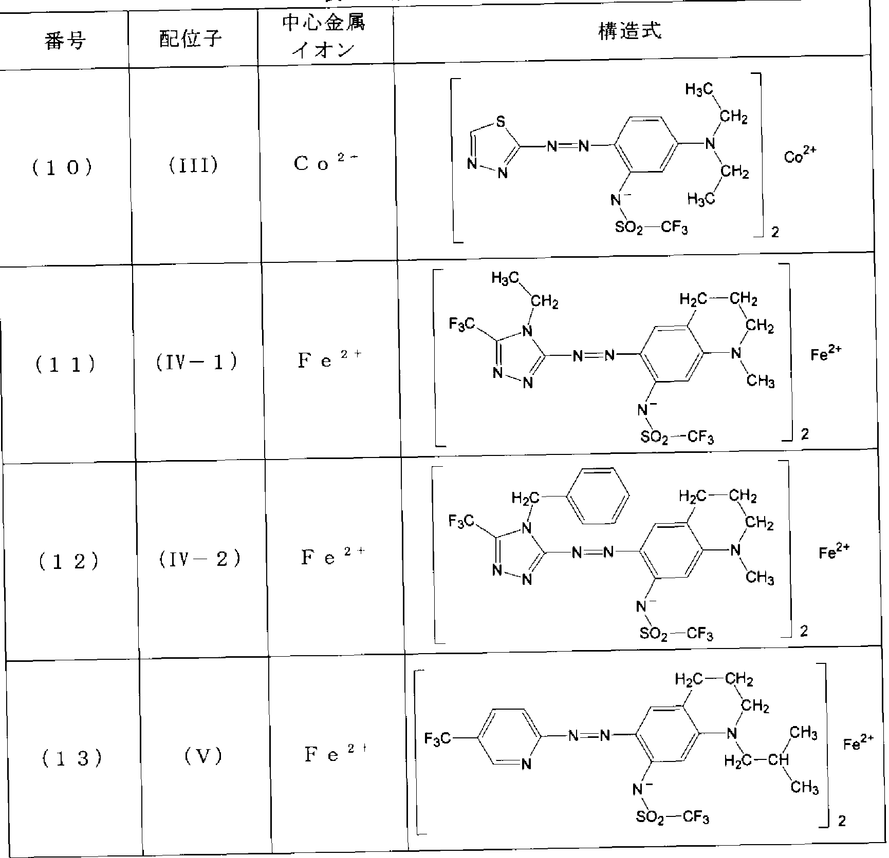

[0200] 上記表 1 4に記載の添加剤(1)〜(17)各 20mgを、 TFP (2,2,3,3,-tetrafluoro- 1 -propanol) 2gに溶解し、 45°Cで 60分超音波分散した。放冷後、得られた分散液を、 可能な場合には 0. 2 mのフィルターで濾過した上で、厚さ 0. 6mmの鏡面基板上 に、回転数 800rpmで 3分間スピンコートし、 80°Cで乾燥させることにより、各添加剤 の単膜サンプルを作製した。
[0201] 〔吸光スペクトルの測定〕
各添加剤単膜サンプルを適当な小片にカットし、基板側から試料光を照射し、空気
をリファレンスとして、波長 400〜800nmの領域における吸収スペクトルを測定した。 測定には日立製作所製分光光度計 U— 3300を用い、波長スキャンスピード 300nm Zmin、サンプリング周期 0. 5nmの吸光度モードで測定を行なった。
[0202] 〔耐光性試験 (色素保持率の測定)〕
各添加剤単膜サンプルを適当な小片にカットし、東洋精機製耐光性試験機サンテ スト XLS +を用いて、 Xeランプ(550WZm2、ブラックパネル温度 63°C)を 40時間照 射した。上記 Xeランプの照射前の吸収極大の吸光度 Iと、 Xeランプの照射後の吸収
0
極大の吸光度 Iとをそれぞれ測定し、 (I /1 ) X 100 (%)により算出される値を、添
1 1 0
加剤の色素保持率とし、耐光性の判定の目安とした。この色素保持率の数値が大き いほど、耐光性が良好であることを示す。
[0203] 〔結果及び評価〕
上記手順により得られた各添加剤(1)〜(17)の単膜サンプルの吸収極大波長及 び色素保持率の結果を下記表 5及び表 6に示す。
[0204] [表 5]
表 5 添加剤単膜サンプルの結果 1

:最も吸光度が大きい吸収ピーク (即ち主吸収帯) の吸光度を 1 0 0とした時の 相対強度を ( ) 内に示す。
[0205] [表 6]
表 6 添加剤単膜サンプルの結果 1

*最も吸光度が大きい吸収ピーク (即ち主吸収帯) の吸光度を 1 0 0とした時の 相対強度を ( ) 内に示す。
[0206] 表 5及び表 6より、中心金属イオンが Co2+の添加剤は、 Ni2+の添加剤よりも吸光度 の大きい吸収帯(主吸収帯と呼ぶことがある。)が長波長側に存在することが多ぐま
た、中心金属イオン力Fe2+の添加剤は、 680nm以上の長波長側に吸収帯が存在 することが多いことがわかる。
[0207] 例えば、配位子 (I 1)を有する添加剤について、その主吸収帯波長を比較すると 、中心金属イオンが Ni2+の場合(添加剤(1) )は 598nmであるのに対して、 Co2+の 場合 (添加剤(3) )は 605nmである。また、中心金属イオンが Fe2+の場合 (添加剤(2 ) )は、主吸収帯の波長は 577. 2nmと短いが、波長 727. 5nmにやや強い吸収帯が 存在する。
[0208] また、キレートイ匕しない状態での吸収への寄与は同等と考えられる配位子 (Π— 1) ,
(II— 2)を有する添加剤を比較すると、キレート後の中心金属イオン力 SNi2+の場合( 添加剤(6) )は主吸収帯が波長 607. 5nmであり、 Cu2+の場合 (添加剤(9) )は主吸 収帯が波長 609nmである。また、中心金属イオンが Co2+の場合 (添加剤(8) )は、 波長 571. 8nmと波長 607. 8nmに 常に強!ヽ吸収帯力 ^あり、更に、波長 681. 3n mにもやや強い吸収が存在する。中心金属イオンが Fe2+の場合 (添加剤(7) )は、主 吸収帯は波長 754. 4nmの長波長領域に存在する力 それよりもはるかに短波長側 の波長 584. 2nmにも強い吸収帯を有する。
[0209] また、図 8 (a) , (b)に、各添加剤単膜の主吸収帯に対する波長 680nm以上の吸 収帯の強度比を表わすグラフを示す。図 8 (a) , (b)より、各中心金属イオンについて 比較すると、一部のァゾ色素化合物を配位子として有する Co2+及び Fe2+では、 Ni2 +、 Cu2+の場合とは異なり、波長 680nm以上の吸収帯が存在することがわかる。
[0210] 更に、図 11に、表 5の(1)〜(13)までの各添加剤の単膜の色素保持率をその中心 金属イオン毎に表わすグラフを示す。図 11より、先に述べたように、 Ni2+、 Cu2+、 Co 2+、 Fe2+を中心金属イオンとする場合には、添加剤自体には耐光性の差が見られな いことがわ力る。
[0211] [実験群 3 (1) :記録層の評価 1]
〔記録層サンプルの作製〕
母体色素として、下記構造式で表わされるァゾ系金属キレート色素 (色素 A)を用い 、添加剤として、上記表 1〜3に示す添加剤(1)〜(13)を用いて、以下の手順により 記録層サンプルを作製した。
[0212] [化 30]

色素 A
[0213] 母体色素(色素 A) 20mgと各添加剤 2mgとを TFP2gに溶解し、 45°Cで 60分超音 波分散した。放冷後、得られた分散液を、可能な場合には 0. 2 mのフィルターで濾 過した上で、厚さ 0. 6mmの鏡面基板上に、回転数 800rpmで 3分間スピンコートし、 80°Cで乾燥させることにより、母体色素及び各添加剤を含有する記録層サンプルを 作製した (後述の表 7における比較例 1 , 2及び実施例 1〜 11)。
[0214] また、対照用サンプルとして、添加剤を加えない他は上と同様の手順により、母体 色素のみ力もなる単膜のサンプルを作製した (後述の表 7における対照例 1)。
[0215] 〔吸光スペクトルの測定及び bZa値の算出〕
得られた記録層サンプル及び対照用サンプルについて、前記 [実験群 2]と同様の 方法により、波長 400〜800nmの領域における吸収スペクトルを測定した。得られた 吸収スペクトルから、先に図 7を用いて説明した手法により、 bZa値を算出した。
[0216] 〔耐光性試験 (色素保持率の測定)〕
各記録層サンプル及び対照用サンプルについて、前記 [実験群 2]と同様の方法に より、耐光性の目安となる色素保持率の測定を行なった。
[0217] 〔結果及び評価〕
上記手順により得られた各記録層サンプルの bZa値及び色素保持率の結果を、下 記表 7に示す。
[0218] [表 7]
記録層サンプルの評価 1 (母体色素 A )

*吸収極大はみられないが、 吸収が全体的に高くなっている。
* *図 7の (a ) 或いは (b ) のいずれの場合であつたかを示す。
[0219] また、図 5 (a), (b)に、各記録層サンプルの耐光性 (色素保持率)に対する、添カロ 剤の中心金属イオンの効果の差を表わすグラフを示す。
[0220] 表 7及び図 5 (a) , (b)より、添加剤の配位子の種類によらず、中心金属イオンが Ni2 +の場合よりも Cu2+、 Co2+、又は Fe2+の場合の方が、一貫してより大きな耐光性の 向上効果が得られていることがわかる。そして、添加剤をカ卩えない母体色素(色素 A) 単独の色素保持率が 0%であるのに対して、中心金属イオンが Co2+の添加剤を加え た場合には 25%〜50%へ、中心金属イオンが Fe2+の添加剤を加えた場合には 45 %〜50%へと大きく変化し、耐光性が非常に向上したことがわかる。この結果から、 中心金属イオン力 ¾u2+、 Co2+、又は Fe2+である上述の添加剤 (本発明の添加剤) は、耐光性の効果が得られ難!、とされてきたァゾ系金属キレート色素である色素 Aに 対しても、優れた耐光性の向上効果を発揮することがわかる。
[0221] [実験群 3 (2) :記録層の評価 2]
〔サンプルの作製〕
母体色素として、下記構造式で表わされるシァニン系金属錯体 (色素 B)を用い、添 加剤として、添加剤として、上記表 1〜3に示す添加剤(1)〜(13)を用いて、上記 [
実験群 3 (1) ]と同様の手順により、記録層サンプルを作製した (後述の表 8における 比較例 3, 4及び実施例 12〜22)。
[0222] [化 31]

色素 B
[0223] また、対照用サンプルとして、添加剤を加えない他は上と同様の手順により、母体 色素 Bのみ力 なる単膜のサンプルを作製した (後述の表 8における対照例 2)。
[0224] 〔bZa値の算出、色素保持率の測定、結果及び評価〕
得られた記録層サンプル及び対照用サンプルについて、前記 [実験群 3 (1) ]と同 様の手順により、吸収スペクトルの測定及び bZa値の算出、並びに耐光性の指標と なる色素保持率の測定を行なった。得られた結果を下記表 8に示す。
[0225] [表 8]
記録層サンプルの評価 2 (母体色素 B )

*吸収極大はみられないが、 吸収が全体的に高くなっている。
* *図 7の (a ) 或いは (b ) のいずれの場合であつたかを示す。
[0226] また、図 6 (a) , (b)に、記録層の耐光性 (色素保持率)に対する、添加剤の中心金 属イオンの効果の差を表わすグラフを示す。
[0227] 表 8及び図 6 (a), (b)から、母体色素としてシァニン系色素である色素 Bを用いた 場合、本発明の添加剤による効果は、前記 [実験群 3 (1) ]に示すように母体色素とし てァゾ系金属キレート色素を用いた場合よりも、非常に高いことがわかる。しかし、中 心金属イオンの違いによる効果の差の傾向は、これら両者の間でも同様である。つま り、前記記録層が、少なくとも、 Cu2+ Fe2+ Co2+の何れかを中心金属イオンとする 金属キレート色素添加剤を含むことにより、大きな耐光性向上効果が得られることが わ力る。
[0228] [実験群 3 (1)及び実験群 3 (2)に関する検討]
図 4及び図 5 (a) , (b)は何れも、実験群 3 (1)及び実験群 3 (2)における記録層サ ンプルの色素保持率を表わすグラフである。具体的に、図 4では、異なる色素 A, Bに 対する中心金属イオンの差に着目するために、配位子 (1—1)を有する添加剤を用 いた場合の結果を示している。また、図 5 (a) , (b)では、色素 Aに対する中心金属ィ オンの差に着目するために、配位子 (1—1) , (1— 2)を有する添加剤を用いた場合の
結果を図 5 (a)に、配位子 (Π—1) , (Π— 2)を有する添加剤を用いた場合の結果を図 5 (b)に、それぞれ分けて示している。
[0229] 耐光性の効果が出難い色素 Aに対する効果に注目すると、図 4及び図 5 (a)より、 配位子が(1—1)のァゾ系色素化合物の場合には、 Fe2+をを中心金属イオンとする 添加剤(添加剤(2) )の効果が、また、図 5 (b)により、配位子が(II— 1)、(II— 2)のァ ゾ系色素化合物の場合には、 Co2+、 Fe2+を中心金属イオンとする添加剤(添加剤( 3)、添加剤(7) )の効果が、それぞれ極めて高いことがわかる。
[0230] また、実験群 3 (1)及び実験群 3 (2)の記録層サンプルの bZa値と耐光性との関係 を表わすグラフを、それぞれ図 9及び図 10として示す。図 9及び図 10より、前述のよう に、 bZa値が 1より大きい場合には、耐光性が安定して向上する傾向が見られること が分かる。
[0231] [実験群 3 (3) :記録層の評価 3]
〔サンプルの作製〕
母体色素として、下記構造式で表わされる青色レーザー記録用の色素 (色素 C)を 用い、添加剤として、上記表 2に示す添加剤(8)及び上記表 4に示す添加剤(14)〜 (17)を用い、上記 [実験群 3 (1) ]と同様の手順により記録層サンプルを作製した (後 述の表 9における実施例 23〜27)。
[0232] [化 32]

色素 C
また、対照用サンプルとして、添加剤を加えない他は上と同様の手順により、母体 色素 Cのみ力もなる単膜のサンプルを作製した (後述の表 9における対照例 3)。
[0234] 〔bZa値の算出、色素保持率の測定、結果及び評価〕
得られた各記録層サンプル及び対照用サンプルについて、前記 [実験群 3 (1) ]と 同様の手順により、吸収スペクトルの測定及び bZa値の算出、並びに耐光性の指標 となる色素保持率の測定を行なった。得られた結果を下記表 9に示す。
[0235] [表 9]
表 9 記録層サンプルの評価 3 (母体色素 C )

*吸収極大はみられないが、 吸収が全体的に高くなっている。
[0236] 表 9に示す結果から、青色レーザー用色素である色素 Cは、色素保持率が 63. 2% と比較的良好であり、添加剤の使用による耐光性の向上効果がで難 、と思われるに もかかわらず、本発明の Fe2+、 Co2+を中心金属イオンとする添加剤(8)及び(14)〜 (17)を加えると、色素保持率が 70%〜90%強へと向上し、明らかな効果が得られる ことが分力 た。その中でも特に、添加剤(8) [ (II— 2) (Co2+)色素添加剤]、添カロ
2
剤 4) [ (VII) (Fe2+)色素添加剤]、添加剤(16) [ (IX) (Fe2+)色素添加剤]及び
2 2
添加剤 7) [ (X) (Fe2+)色素添加剤]の効果が優れていると言える。
2
[0237] [実験群 3 (4):記録層の評価 4]
〔サンプルの作製〕
母体色素として、下記構造式で表わされる色素 (色素 D)を用い、添加剤として、上 記表 2に示す添加剤(8)及び上記表 4に示す添加剤(14)〜(17)を用い、上記 [実 験群 3 (1) ]と同様の手順により記録層サンプルを作製した (後述の表 10における実 施例 28〜 32)。
[0238] [化 33]

母体色素 D
[0239] また、対照用サンプルとして、添加剤をカ卩えない他は上と同様の手順により、母体 色素 Dのみ力もなる単膜のサンプルを作製した (後述の表 10における対照例 4)。
[0240] 〔bZa値の算出、色素保持率の測定、結果及び評価〕
得られた各記録層サンプル及び対照用サンプルについて、前記 [実験群 3 (1) ]と 同様の手順により、吸収スペクトルの測定及び bZa値の算出、並びに耐光性の指標 となる色素保持率の測定を行なった。得られた結果を下記表 10に示す。
[0241] [表 10]
表 1 0 記録層サンプルの評価 4 (母体色素 D )

*吸収極大はみられないが、 吸収が全体的に高くなっている。
* *図 7の (a ) 或いは (b ) のいずれの場合であつたかを示す。
[0242] 表 10の結果から、本発明の Fe2+, C。2+を中心金属イオンとする添加剤(8)及び( 14)〜(17)を用いると、色素保持率が 70%〜90%強へと向上することから、極めて 良好な耐光性向上効果を有することがわかる。その中でも特に、添加剤(8) [ (II— 2) (Co2+)色素添加剤]、添加剤(16) [ (IX) (Fe2+)色素添加剤]及び添加剤(17) [ ( X) (Fe2+)
2 色素添加剤]の効果が優れて!/、ると言える。
[0243] なお、添加剤(8)及び添加剤(17)の色素単膜の吸収スペクトルをそれぞれ図 12 (
a) , (b)に示す。何れも通常の記録層のァゾ系金属キレート色素としては通常見られ ない極めてブロードな吸収帯の重なりが見られることが分かる。
[0244] [実験群 4 :光記録媒体の評価]
〔光記録媒体の作製〕
前記 [実験群 3 (4) ]に記載の色素 D (母体色素)を 35重量%、及び、前記 [実験群 2]の表 1の色素(1)を 60重量%、また、添加剤として、前記 [実験群 2]の表 1の色素 (2)を 5重量%の割合で用いた。これらの色素 D、色素(1)、及び色素(2)を、その合 計の濃度が 1. 3重量%となるように TFPに溶解させ、記録層形成用の塗布液を作製 した。
[0245] 得られた塗布液を、トラックピッチ 0. 74 μ m、溝幅 320nm、溝深さ 60nmの案内溝 を有する厚さ 0. 6mmの支持基板上に、スピンコート法(回転数 1000rpm〜6000rp m)により、吸光度 (空気をリファレンスとして測定した波長 598nmにおける吸光度) 0 . 65を示す厚みとなるように成膜し、記録層を設けた。得られた記録層の溝部膜厚は 50nmであった。
[0246] 次いで、その記録層の上にスパッタリング法で銀を堆積させ、厚さ 120nmの銀反射 膜を設けた。更に、日本化薬 (株)製 KAYARAD SPC— 920を 10 mの厚さとなる よう塗布して保護層を形成した。
[0247] 以上の手順で作製した積層体を 2枚用意し、 UV硬化型接着剤 (ソニーケミカル製 SK7100)を用いて、基板が外側になるように貼り合わせることにより、光ディスク (光 記録媒体)を作製した。
[0248] 〔記録試験〕
得られた光ディスクに対し、波長 650nm、開口数 0. 65の記録再生装置を用いて、 DVD-R Specification for General Ver.2.1や DVD+R Specification Ver.1.20に準拠し た記録パルスストラテジー条件に基づいて、記録速度 28. OmZs (DVD— Rの 8倍 速)において、最短マーク長が 0. 4 mである EFMプラス変調のランダム信号記録 を行なった。そして、同じ評価機を用いて記録した部分の信号を再生したところ、良 好な再生信号を得た。
[0249] 〔耐光性試験〕
また、この光ディスクに対して、東洋精機製耐光性試験機サンテスト XLS +を用い て、 Xeランプ(550WZm2、ブラックパネル温度 63°C)を 40時間照射(Wool scale 5級に相当)した後、上述の評価機を用いて上記記録部分の信号の再生を行なった ところ、良好な再生信号が得られたことから、耐光性が改善されていることが分力つた
[0250] [比較実験群 1]
前記の [実験群 3 (1) ]において、前記表 1〜3記載の添加剤(1)〜(13)の代わりに 、一重項酸素クェンチヤ一として従来知られてきた、下記構造式で表わされる化合物 (Q1)〜(Q5)を添加した以外は、 [実験群 3 (1) ]と同じ手順で記録層サンプルを作 製し、耐光性試験 (色素保持率の測定)を行なった (後述の表 11の比較例 5〜9)。
[0251] [化 34]

[0252] [化 35]

[0253] [化 36]

[0254] [化 37]

[0255] [化 38]

[0256] 得られた結果を下記の表 11に示す。表 11から明らかなように、何れの一重項酸素
クェンチヤ一(QD〜(Q5)を用いた場合も、良好な結果は得られな力 た。
[0257] [表 11]
表 1 1 記録層サンプルの評価 5 (母体色素 A )

( ) 内に示す。
[0258] [比較実験群 2]
前記の [実験群 3 (2) ]にお!/、て、前記表 1〜3記載の添加剤(1)〜(13)の代わりに 、上述の化合物(Q4) (—重項酸素クェンチヤ一)を添加した以外は、 [実験群 3 (2) ] と同じ手順で記録層サンプルを作製し、耐光性試験 (色素保持率の測定)を行なった (比較例 10)。
[0259] 得られた結果を表 12に示す。表 12から明らかなように、耐光性向上の効果は見ら れなかった。
[0260] [表 12]
記録層サンプルの評価 6 (母体色素 B )

産業上の利用可能性
[0261] 本発明は、 DVD士 R等の赤色半導体レーザー用の光記録媒体や、青色半導体レ 一ザ一用の光記録媒体等の用途において、好適に利用することが可能である。
[0262] 以上、本発明を特定の態様を用いて詳細に説明したが、本発明の意図と範囲を離 れることなく様々な変更が可能であることは当業者に明らかである。
なお、本出願は、 2005年 8月 10曰付で出願された特願 2005— 231901号明細
書に基づいており、その全体が引用により援用される。
Claims
請求の範囲
[1] 基板と、前記基板上に設けられ、 700nm以下の波長の光が照射されることにより情 報の記録又は再生が可能な母体色素を含有する記録層と、反射層とを有する光記 録媒体において、
該記録層が、少なくとも、 Cu2+、 Fe2+及び Co2+のうち何れかを中心金属イオンとす るァゾ系金属キレート色素添加剤を含有する
ことを特徴とする、光記録媒体。
[2] 前記ァゾ系金属キレート色素添加剤の中心金属イオン力Fe2+又は Co2+である ことを特徴とする、請求項 1記載の光記録媒体。
[3] 前記ァゾ系金属キレート色素添加剤を、該記録層の母体色素に対して 0. 1重量% 以上、 50重量%以下の濃度で含有する
ことを特徴とする、請求項 1又は請求項 2に記載の光記録媒体。
[4] 前記ァゾ金属キレート色素添加剤が、膜或いは溶液の状態で、 400nm〜630nm の波長範囲及び 680nm〜800nmの波長範囲にそれぞれ一以上の吸収極大を有 する
ことを特徴とする、請求項 1記載の光記録媒体。
[5] 前記記録層が、 400nm〜630nmの波長範囲及び 680nm〜800nmの波長範囲 にそれぞれ一以上の吸収極大を有する
ことを特徴とする、請求項 1記載の光記録媒体。
[6] 前記母体色素が、下記一般式 (I)で表わされるァゾィ匕合物から Xの有する活性水 素が脱離した配位子と、 Zn2+とから形成されるァゾ系金属キレート色素である ことを特徴とする、請求項 1〜5の何れか一項に記載の光記録媒体。
[化 1]

(一般式 (I)中、
環 Aは、置換基を有してもよい芳香族複素環を表わし、
Xは、活性水素を有する有機基を表わし、
環 Bは、 Xの他に置換基を有してもよい芳香環又は芳香族複素環を表わす。 ) 前記母体色素が、下記一般式 (II)で表わされるシァニン系色素である
ことを特徴とする、請求項 1〜5の何れか一項に記載の光記録媒体。
[化 2]

(一般式 (II)中、
環 C及び環 Dは各々独立に、インドレニン環、ベンゾインドレニン環、又はジベンゾィ ンドレニン環を表わし、
Lは、モノメチン基又はトリメチン基を表わし、
R1及び R2は各々独立に、置換基を有してもよいアルキル基を表わす。 )
下記一般式 (III)で表わされるァゾィ匕合物から Xの有する活性水素が脱離した配位 子が 2つと、 Fe2+とから形成される
ことを特徴とする、ァゾ系鉄キレート色素。
[化 3]

(一般式 (III)中、
環 Eは、置換基を有してもよい芳香族複素環を表わし、
Xは、活性水素を有する有機基を表わし、
R3及び R4は各々独立に、置換基を有してもよいアルキル基を表わす。但し、 R3と R'
同士が結合して環を形成していてもよぐまた、 R3及び R4の一方又は両方がベンゼ ン環と結合して、ベンゼン環に縮合する 4〜7員環を形成してもよ 、。
なお、 2つの配位子が有する環 E、 X、 R3及び R4は何れも、互いに同じであってもよく 、異なっていてもよい。 )
[9] 光記録媒体の記録層に用いられる添加剤であって、
請求項 8記載のァゾ系鉄キレート色素力 なる
ことを特徴とする、ァゾ系金属キレート色素添加剤。
[10] 光記録媒体の記録層に用いられる添加剤であって、
下記一般式 (IV)で表わされるァゾィ匕合物から Xの有する活性水素が脱離した配位 子が 2つと、 Co2+とから形成され、
膜或 ヽは溶液の状態で、 400nm〜630nmの波長範囲及び 680nm〜800nmの 波長範囲にそれぞれ一以上の吸収極大を有する
ことを特徴とする、ァゾ系金属キレート色素添加剤。
[化 4]

(一般式 (IV)中、
環 Eは、置換基を有してもよい芳香族複素環を表わし、
Xは、活性水素を有する有機基を表わし、
R3及び R4は各々独立に、置換基を有してもよいアルキル基を表わす。但し、 R3と R4 同士が結合して環を形成していてもよぐまた、 R3及び R4の一方又は両方がベンゼ ン環と結合して、ベンゼン環に縮合する 4〜7員環を形成してもよ 、。
なお、 2つの配位子が有する環 E、 X、 R3及び R4は何れも、互いに同じであってもよく 、異なっていてもよい。 )
Priority Applications (4)
| Application Number | Priority Date | Filing Date | Title |
|---|---|---|---|
| US12/063,488 US20090291246A1 (en) | 2005-08-16 | 2006-08-10 | Optical recording medium, azo-type iron chelate coloring matter, and azo-type metal chelate coloring matter additive |
| EP06796327A EP1930172B1 (en) | 2005-08-10 | 2006-08-10 | Optical recording medium, azo-type iron chelate coloring matter, and azo-type metal chelate coloring matter additive |
| CN2006800290756A CN101237995B (zh) | 2005-08-10 | 2006-08-10 | 光记录介质、偶氮系铁螯合物色素和偶氮系金属螯合物色素添加剂 |
| HK08112209.4A HK1122770A1 (en) | 2005-08-10 | 2008-11-06 | Optical recording medium, azo iron chelate dye and azo metal-chelate dye additive |
Applications Claiming Priority (2)
| Application Number | Priority Date | Filing Date | Title |
|---|---|---|---|
| JP2005-231901 | 2005-08-10 | ||
| JP2005231901A JP4750504B2 (ja) | 2005-08-10 | 2005-08-10 | 光記録媒体及びアゾ系金属キレート色素添加剤 |
Publications (1)
| Publication Number | Publication Date |
|---|---|
| WO2007018263A1 true WO2007018263A1 (ja) | 2007-02-15 |
Family
ID=37727443
Family Applications (1)
| Application Number | Title | Priority Date | Filing Date |
|---|---|---|---|
| PCT/JP2006/315828 WO2007018263A1 (ja) | 2005-08-10 | 2006-08-10 | 光記録媒体、アゾ系鉄キレート色素及びアゾ系金属キレート色素添加剤 |
Country Status (6)
| Country | Link |
|---|---|
| EP (1) | EP1930172B1 (ja) |
| JP (1) | JP4750504B2 (ja) |
| CN (1) | CN101237995B (ja) |
| HK (1) | HK1122770A1 (ja) |
| TW (1) | TW200710842A (ja) |
| WO (1) | WO2007018263A1 (ja) |
Cited By (2)
| Publication number | Priority date | Publication date | Assignee | Title |
|---|---|---|---|---|
| EP2070989A1 (en) * | 2006-09-25 | 2009-06-17 | Mitsubishi Kagaku Media Co., Ltd. | Metal-chelate azo dye and optical recording medium |
| WO2009154289A1 (ja) * | 2008-06-17 | 2009-12-23 | リンテック株式会社 | 多層光記録媒体用シート及びそれを用いてなる多層光記録媒体 |
Families Citing this family (3)
| Publication number | Priority date | Publication date | Assignee | Title |
|---|---|---|---|---|
| JP2009114345A (ja) * | 2007-11-07 | 2009-05-28 | Yamada Chem Co Ltd | 金属錯体化合物、光学記録媒体、光記録材料及び色素 |
| JP5352986B2 (ja) * | 2007-11-07 | 2013-11-27 | 山田化学工業株式会社 | 金属錯体化合物、光学記録媒体及び光記録材料 |
| CN103059065B (zh) * | 2011-10-20 | 2015-04-22 | 上海拓引数码技术有限公司 | 一种偶氮类金属络合物及其制备方法 |
Citations (7)
| Publication number | Priority date | Publication date | Assignee | Title |
|---|---|---|---|---|
| JPS5955794A (ja) | 1982-09-25 | 1984-03-30 | Tdk Corp | 光記録媒体 |
| JPH0939394A (ja) * | 1995-07-24 | 1997-02-10 | Ricoh Co Ltd | 光情報記録媒体 |
| JPH09323478A (ja) | 1996-06-06 | 1997-12-16 | Tdk Corp | 光記録媒体 |
| JP2000190641A (ja) | 1998-12-29 | 2000-07-11 | Tdk Corp | 光記録媒体 |
| JP2001199169A (ja) * | 2000-01-20 | 2001-07-24 | Mitsubishi Chemicals Corp | 光学記録媒体 |
| JP2005051719A (ja) | 2003-07-31 | 2005-02-24 | Toshiba Corp | 垂直のこぎり波振幅調整装置 |
| JP2005131925A (ja) | 2003-10-30 | 2005-05-26 | Mitsubishi Pencil Co Ltd | 加圧式のボールペン |
Family Cites Families (3)
| Publication number | Priority date | Publication date | Assignee | Title |
|---|---|---|---|---|
| JP2001277721A (ja) * | 2000-03-30 | 2001-10-10 | Ricoh Co Ltd | 光記録媒体および該光記録媒体を用いた光記録再生方法 |
| JP4523366B2 (ja) * | 2003-09-11 | 2010-08-11 | 三菱化学メディア株式会社 | アゾ金属キレート色素及び光学記録媒体 |
| JP4481000B2 (ja) * | 2003-12-25 | 2010-06-16 | 三菱化学メディア株式会社 | アゾ金属キレート色素及び光学記録媒体 |
-
2005
- 2005-08-10 JP JP2005231901A patent/JP4750504B2/ja not_active Expired - Fee Related
-
2006
- 2006-08-10 CN CN2006800290756A patent/CN101237995B/zh not_active Expired - Fee Related
- 2006-08-10 EP EP06796327A patent/EP1930172B1/en not_active Expired - Fee Related
- 2006-08-10 TW TW095129335A patent/TW200710842A/zh unknown
- 2006-08-10 WO PCT/JP2006/315828 patent/WO2007018263A1/ja active Application Filing
-
2008
- 2008-11-06 HK HK08112209.4A patent/HK1122770A1/xx not_active IP Right Cessation
Patent Citations (7)
| Publication number | Priority date | Publication date | Assignee | Title |
|---|---|---|---|---|
| JPS5955794A (ja) | 1982-09-25 | 1984-03-30 | Tdk Corp | 光記録媒体 |
| JPH0939394A (ja) * | 1995-07-24 | 1997-02-10 | Ricoh Co Ltd | 光情報記録媒体 |
| JPH09323478A (ja) | 1996-06-06 | 1997-12-16 | Tdk Corp | 光記録媒体 |
| JP2000190641A (ja) | 1998-12-29 | 2000-07-11 | Tdk Corp | 光記録媒体 |
| JP2001199169A (ja) * | 2000-01-20 | 2001-07-24 | Mitsubishi Chemicals Corp | 光学記録媒体 |
| JP2005051719A (ja) | 2003-07-31 | 2005-02-24 | Toshiba Corp | 垂直のこぎり波振幅調整装置 |
| JP2005131925A (ja) | 2003-10-30 | 2005-05-26 | Mitsubishi Pencil Co Ltd | 加圧式のボールペン |
Non-Patent Citations (1)
| Title |
|---|
| See also references of EP1930172A4 |
Cited By (4)
| Publication number | Priority date | Publication date | Assignee | Title |
|---|---|---|---|---|
| EP2070989A1 (en) * | 2006-09-25 | 2009-06-17 | Mitsubishi Kagaku Media Co., Ltd. | Metal-chelate azo dye and optical recording medium |
| EP2070989A4 (en) * | 2006-09-25 | 2009-11-11 | Mitsubishi Kagaku Media Co Ltd | METAL CHELATAZO DYE AND OPTICAL RECORDING CARRIER |
| WO2009154289A1 (ja) * | 2008-06-17 | 2009-12-23 | リンテック株式会社 | 多層光記録媒体用シート及びそれを用いてなる多層光記録媒体 |
| JPWO2009154289A1 (ja) * | 2008-06-17 | 2011-12-01 | リンテック株式会社 | 多層光記録媒体用シート及びそれを用いてなる多層光記録媒体 |
Also Published As
| Publication number | Publication date |
|---|---|
| JP4750504B2 (ja) | 2011-08-17 |
| CN101237995A (zh) | 2008-08-06 |
| CN101237995B (zh) | 2010-12-08 |
| EP1930172A1 (en) | 2008-06-11 |
| HK1122770A1 (en) | 2009-05-29 |
| JP2007044995A (ja) | 2007-02-22 |
| EP1930172A4 (en) | 2010-08-04 |
| EP1930172B1 (en) | 2012-07-04 |
| TW200710842A (en) | 2007-03-16 |
Similar Documents
| Publication | Publication Date | Title |
|---|---|---|
| JP3897695B2 (ja) | 短波長対応のロー・ツー・ハイ記録極性を有する追記型光記録媒体 | |
| US20090291246A1 (en) | Optical recording medium, azo-type iron chelate coloring matter, and azo-type metal chelate coloring matter additive | |
| TWI298881B (ja) | ||
| WO2007074861A1 (ja) | 光学記録媒体及びアザシアニン色素 | |
| WO2007018263A1 (ja) | 光記録媒体、アゾ系鉄キレート色素及びアゾ系金属キレート色素添加剤 | |
| JP4178783B2 (ja) | 光学記録媒体 | |
| JPH10330633A (ja) | サブフタロシアニン化合物及びそれを用いた光記録媒体 | |
| JP2004001375A (ja) | 追記型光記録媒体及び該光記録媒体用記録剤 | |
| JP5283573B2 (ja) | 光情報記録媒体用色素及びそれを用いた光情報記録媒体 | |
| JP2006331619A (ja) | 光記録媒体、スパッタリングターゲット及びアゾ金属キレート色素 | |
| WO2006120205A2 (en) | Anionic phthalocyanine based dyes for use as bca dye in an optical recording layer for blue laser recording | |
| JP5352986B2 (ja) | 金属錯体化合物、光学記録媒体及び光記録材料 | |
| AU2006210275A1 (en) | Cationic antipyrine based azo metal complex dyes for use in optical layers for optical data recording | |
| JP2004127472A (ja) | 光記録媒体とその記録方法 | |
| JP3608873B2 (ja) | 光記録媒体 | |
| JP2005243165A (ja) | 光情報記録媒体 | |
| TW201009833A (en) | Optical information recording medium | |
| JP5205521B2 (ja) | 光情報記録媒体用色素及びそれを用いた光情報記録媒体 | |
| JP2005131816A (ja) | 短波長対応の追記型光記録媒体 | |
| JP3980092B2 (ja) | 光記録媒体 | |
| JP2008262671A (ja) | 追記型光情報記録媒体 | |
| JP2004098673A (ja) | 光学記録媒体および光学記録方法 | |
| JP2001076343A (ja) | 光記録媒体及び光記録方式 | |
| JP2010009712A (ja) | 光情報記録媒体 | |
| JPH10166732A (ja) | 光記録媒体 |
Legal Events
| Date | Code | Title | Description |
|---|---|---|---|
| WWE | Wipo information: entry into national phase |
Ref document number: 200680029075.6 Country of ref document: CN |
|
| 121 | Ep: the epo has been informed by wipo that ep was designated in this application | ||
| WWE | Wipo information: entry into national phase |
Ref document number: 12063488 Country of ref document: US |
|
| NENP | Non-entry into the national phase |
Ref country code: DE |
|
| WWE | Wipo information: entry into national phase |
Ref document number: 623/KOLNP/2008 Country of ref document: IN |
|
| WWE | Wipo information: entry into national phase |
Ref document number: 2006796327 Country of ref document: EP |