WO2006098227A1 - 帯状アルミニウム板の陽極酸化処理方法、平版印刷版材料用支持体及び陽極酸化処理装置 - Google Patents
帯状アルミニウム板の陽極酸化処理方法、平版印刷版材料用支持体及び陽極酸化処理装置 Download PDFInfo
- Publication number
- WO2006098227A1 WO2006098227A1 PCT/JP2006/304686 JP2006304686W WO2006098227A1 WO 2006098227 A1 WO2006098227 A1 WO 2006098227A1 JP 2006304686 W JP2006304686 W JP 2006304686W WO 2006098227 A1 WO2006098227 A1 WO 2006098227A1
- Authority
- WO
- WIPO (PCT)
- Prior art keywords
- strip
- aluminum plate
- shaped aluminum
- anodizing
- shaped
- Prior art date
- Legal status (The legal status is an assumption and is not a legal conclusion. Google has not performed a legal analysis and makes no representation as to the accuracy of the status listed.)
- Ceased
Links
Classifications
-
- B—PERFORMING OPERATIONS; TRANSPORTING
- B41—PRINTING; LINING MACHINES; TYPEWRITERS; STAMPS
- B41N—PRINTING PLATES OR FOILS; MATERIALS FOR SURFACES USED IN PRINTING MACHINES FOR PRINTING, INKING, DAMPING, OR THE LIKE; PREPARING SUCH SURFACES FOR USE AND CONSERVING THEM
- B41N3/00—Preparing for use and conserving printing surfaces
- B41N3/03—Chemical or electrical pretreatment
- B41N3/034—Chemical or electrical pretreatment characterised by the electrochemical treatment of the aluminum support, e.g. anodisation, electro-graining; Sealing of the anodised layer; Treatment of the anodic layer with inorganic compounds; Colouring of the anodic layer
Definitions
- the present invention relates to an anodizing method for forming an anodized film on an aluminum plate surface, an anodizing apparatus used in the anodizing method, and a lithographic printing plate produced using the anodizing method
- the present invention relates to an aluminum support used for the material.
- An aluminum plate used as a support for a lithographic printing plate has a surface that has been subjected to surface roughening and anodizing treatment in order to impart printability such as water retention and printing durability. Widely used.
- a strip-shaped metal plate is continuously run in an electrolytic solution, and a current is passed between the metal plate and an electrode developed on the one surface.
- an electric insulating plate is directly disposed on the back side of the metal plate opposite to the electrode in the region where the electrolytic treatment is performed.
- a method of forming a anodic oxide film by placing a strip-shaped workpiece between an anode and a cathode for example, applying (+) electricity in an electrolytic cell filled with an electrolytic solution.
- Electricity supply The electrode electrode and the electrolytic electrode to which electricity is applied are countered in parallel planes, and a slit plate is provided for each of the counter electrodes in the traveling direction of the continuous strip-shaped workpiece passing between the counter electrodes.
- the gap between the slit part and the object to be processed is arranged and partitioned within a few millimeters, and the slit part force is continuously applied to both side edge parts of the object, and the tip groove part is connected to the ear part.
- the mask separator is arranged in a flat plane with a gap in the thickness direction of the workpiece and the object to be processed of about 1 mm and a depth of fitting into the end ear within a few mm in relation to the accuracy of the plate function. It is characterized in that the surface of the object to be processed is separately faced so as to surround the electric field of each electrode, and the electric current flowing in the object to be processed flows in the front and back direction by making the section electrically independent.
- a method using a single-sided processing device for continuous coil anodized by DC electrolysis (Patent text) 3 reference) are known.
- Patent Document 1 Japanese Patent Application Laid-Open No. 57-47894
- Patent Document 2 Japanese Patent Publication No. 63-58233
- Patent Document 3 Japanese Patent Publication No. 58-24517
- An object of the present invention is to provide a method for anodizing a strip-shaped aluminum plate with little power loss, an anodizing apparatus used therefor, and a lithographic printing plate material support obtained by the processing method. There is.
- a method for anodizing a strip-shaped aluminum plate in an electrolyte contained in an electrolytic cell wherein a strip-shaped aluminum plate is disposed between an anode and a cathode facing each other in the electrolyte, and the cathode and the strip-shaped aluminum plate are disposed.
- An electrical insulator having a current-carrying part is disposed between the aluminum plate and the current-carrying part is located within 35% from the outside with respect to the width in the width direction of the belt-like aluminum plate, and the area of the belt-like aluminum plate If the relationship between the ratio S (%) of the current-carrying area to the distance T (mm) between the strip-like aluminum plate and the electrical insulator is 5 (%) ⁇ S (%) ⁇ 30 (%) 0.2 ⁇ T ⁇ 6 XS— ° ⁇ 8 , and electricity is passed between the anode and the strip-shaped aluminum plate through the current-carrying portion to form an anodic oxide film on the surface of the strip-shaped aluminum plate facing the cathode.
- a method for anodizing a strip-shaped aluminum plate characterized by this.
- the strip-shaped aluminum plate is caused to travel in the longitudinal direction between the anode and the cathode in the electrolytic solution, and the energizing portion is a slit-like opening in the longitudinal direction.
- a support for a lithographic printing plate material which is anodized by the anodizing method for a strip-shaped aluminum plate described in 10.
- An anodizing apparatus characterized by being used in the method for anodizing a strip-shaped aluminum plate according to any one of L0.
- anodizing treatment of a strip-shaped aluminum plate with less power loss there can be provided a method, an anodizing apparatus used therefor, and a lithographic printing plate material support obtained by the treatment method.
- FIG. 1 (a) is a side view showing one embodiment of the anodizing treatment apparatus of the present invention.
- FIG. 1 (b) is a cross-sectional view of the electrolytic cell (used in the example) of the anodizing treatment apparatus of FIG. 1 (a) as seen from the line AA ′.
- FIG. 2 is a plan view of the anodizing treatment apparatus (a view in which the electrolytic solution 2 is removed).
- FIG. 3 is a side view showing an example of a conventional processing apparatus having a power supply tank.
- FIG. 4 is a plan view showing an example of the shape of an electrical insulator.
- the present invention is a method for anodizing a strip-shaped aluminum plate in an electrolyte contained in an electrolytic cell, wherein the strip-shaped aluminum plate is disposed between an anode and a cathode facing each other in the electrolyte, An electrical insulator having a current-carrying portion is disposed between the aluminum plate and the current-carrying portion, and the current-carrying portion is within a position of 35% from the outside with respect to the lateral length of the belt-like aluminum plate, The ratio S (%) of the current-carrying area to the area of the strip and the strip-shaped aluminum The relationship between the distance T (mm) between the new plate and the electrical insulator is 5 (%) ⁇ S (%) ⁇ 30 (%) and 0.
- the strip-shaped aluminum plate according to the present invention is a strip-shaped aluminum plate, and as the material thereof, either a pure aluminum plate or an aluminum alloy plate can be used.
- Various aluminum alloys can be used, for example, alloys of metals such as silicon, copper, manganese, magnesium, chromium, zinc, lead, bismuth, nickel, titanium, sodium, iron, and aluminum are used. Aluminum plates manufactured by various rolling methods can be used.
- a recycled aluminum plate obtained by rolling recycled aluminum bullion such as scrap material and recycled material, which has been spreading in recent years, can also be used.
- the anodizing treatment Before the anodizing treatment according to the present invention, it is preferable to perform a roughening treatment (graining treatment), and it is preferable to perform a degreasing treatment to remove rolling oil on the surface prior to roughening. .
- a degreasing treatment using a solvent such as trichlene or thinner an emulsion degreasing treatment using an emulsion such as kesilon or triethanol, or the like is used.
- an alkaline aqueous solution such as caustic soda can be used for the degreasing treatment.
- an alkaline aqueous solution such as caustic soda is used for the degreasing treatment, it can be removed only by the above degreasing treatment, and if it becomes dirty, the oxide film can also be removed.
- an alkaline aqueous solution such as caustic soda is used for the degreasing treatment, smut is generated on the surface of the support. In this case, it is immersed in an acid such as phosphoric acid, nitric acid or sulfuric acid, or a mixed acid thereof and subjected to a desmut treatment. It is preferable.
- a roughening treatment is performed.
- the surface roughening method include a mechanical surface roughening method and an electrolytic surface roughening treatment using electrolysis mainly composed of nitric acid or hydrochloric acid.
- the mechanical surface roughening method is not particularly limited, but a brush polishing method and a Houng polishing method are preferable.
- the roughening by the brush polishing method is, for example, a brush having a diameter of 0.2 to 0.8 mm.
- For roughing by Houng polishing for example, volcanic ash particles with a particle size of 10 to 100 ⁇ m are uniformly dispersed in water, injected with pressure from a nozzle, and collided with the surface of the support at an angle.
- abrasive particles having a particle diameter of 10 to 100 / ⁇ ⁇ are formed on the support surface at a density of 2.5 to 10 3 to 10 ⁇ 10 3 particles / cm 2 at intervals of 100 to 200 / ⁇ ⁇ . It is also possible to perform roughening by laminating the coated sheets so as to exist in step 1 and transferring the rough surface pattern of the sheet by applying pressure.
- the surface is roughened by the mechanical surface roughening method, it is preferable to immerse in an aqueous solution of acid or alkali in order to remove the abrasive that has digged into the surface of the support, formed aluminum scraps, and the like.
- the acid include sulfuric acid, persulfuric acid, hydrofluoric acid, phosphoric acid, nitric acid, hydrochloric acid, and the like.
- the base include sodium hydroxide, potassium hydroxide, and the like. Among these, it is preferable to use an alkaline aqueous solution such as sodium hydroxide.
- the amount of aluminum dissolved on the surface is preferably 0.5 to 5 g / m 2 .
- the electrolytic surface roughening treatment performed in an electrolytic solution mainly composed of nitric acid is generally performed by applying a voltage in the range of 1 to 50 volts. Possible force It is preferable to select from the range of 10 to 30 volts.
- the current density is preferably a force that can use a range of 10 to 200 A / dm 2 20 to: a range force of LOOAZdm 2 .
- the electric quantity can be in the range of 100 to 2000 c / dm 2 , but is preferably selected from the range of 300 to 1500 cZdm 2 .
- the temperature at which the electrochemical surface roughening method is performed may be in the range of 10 to 50 ° C, but it is preferable to select the range force in the range of 15 to 45 ° C.
- the concentration of nitric acid in the electrolytic solution is preferably 0.1 to 5% by mass. If necessary, the electrolyte can contain nitrates, chlorides, amines, aldehydes, phosphoric acid, chromic acid, boric acid, acetic acid, oxalic acid, aluminum salts, and the like.
- the electrolytic surface roughening treatment is performed in the above nitric acid electrolytic solution, it is preferably immersed in an aqueous solution of acid or alkali in order to remove surface acid-aluminum waste and the like.
- an acid For example, sulfuric acid, persulfuric acid, hydrofluoric acid, phosphoric acid, nitric acid, hydrochloric acid and the like are used, and as the base, for example, sodium hydroxide, potassium hydroxide and the like are used.
- an alkaline aqueous solution it is preferable to use an alkaline aqueous solution.
- the amount of aluminum dissolved on the surface is preferably 0.1 to 2 g / m 2 .
- neutralization treatment is performed by immersion in an acid such as phosphoric acid, nitric acid, sulfuric acid, chromic acid or a mixed acid thereof.
- hydrochloric acid electrolytic solution In the electrolytic surface roughening treatment in an electrolytic solution mainly composed of hydrochloric acid (hereinafter referred to as hydrochloric acid electrolytic solution!),
- the hydrochloric acid concentration is 5 to 20 gZl, preferably 6 to 15 gZl.
- the current density is 15 to 200 A Zdm 2 , preferably 20 to 150 AZdm 2 .
- the amount of electricity is 400 to 2000 CZdm 2 , preferably 500 to 1500 CZdm 2 .
- the frequency is preferably in the range of 40 to 150 Hz.
- the temperature of the electrolytic solution can be in the range of 10-50 ° C, but it is preferable to select a range force of 15-45 ° C.
- nitrates, chlorides, amines, aldehydes, phosphoric acid, boric acid, acetic acid, oxalic acid, aluminum salts, and the like can be added as necessary.
- the electrolytic surface roughening treatment is performed in the above hydrochloric acid electrolyte, it is preferably immersed in an acid or alkali aqueous solution in order to remove surface acid-aluminum scraps and the like.
- the acid include sulfuric acid, persulfuric acid, hydrofluoric acid, phosphoric acid, nitric acid, hydrochloric acid, and the like.
- the base include sodium hydroxide, potassium hydroxide, and the like.
- the amount of aluminum dissolved on the surface is preferably 0.1 to 2 gZm2. It is also preferable to carry out a neutralization treatment after immersion treatment with an aqueous alkali solution and then immersion in an acid such as phosphoric acid, nitric acid or sulfuric acid or a mixed acid thereof.
- Arithmetic mean roughness (Ra) of the roughened surface is preferably 0.3 to 0.8 ⁇ m in terms of conditions such as electrolyte concentration, current density, and quantity of electricity in the roughening treatment. It can be controlled in combination.
- the anodizing method according to the present invention is preferably performed after the roughening as described above.
- FIG. 1 (a) is a side view showing one embodiment of the anodizing apparatus of the present invention
- FIG. 1 (b) is an electrolytic cell of the anodizing treatment apparatus of FIG. 1 (a).
- Straight line A (used in the examples below) It is sectional drawing seen from -A '.
- FIG. 2 is a plan view of the anodizing treatment apparatus (when the electrolytic solution 2 is removed).
- FIG. 3 is a side view showing an example of a conventional processing apparatus having a power supply tank.
- FIG. 4 is a plan view showing an example of the shape of the electrical insulator.
- the strip-shaped aluminum plate 1 is conveyed through the roller 4 in the electrolytic cell 3 filled with the electrolytic solution 2 and anodized.
- the anode 5 and the cathode 6 are arranged to face each other with the strip-shaped aluminum plate 1 running in the electrolytic solution 2 interposed therebetween.
- the energization part according to the present invention refers to an opening provided in an electrical insulator.
- a voltage is applied between the anode 5 and the cathode 6 (by the electric supply means 21) while the strip-shaped aluminum plate 1 is running, so that a current flows from the anode 5 to the strip-shaped aluminum plate 1 through the current-carrying portion 8, and further the strip-shaped aluminum plate A current flows from the plate 1 to the cathode 6, and an anodized film is formed on the surface of the strip-shaped aluminum plate 1 facing the cathode 6.
- the energizing portion 8 according to the present invention is provided from the outside with respect to the length in the width direction of the strip-shaped aluminum plate 1.
- the outer side means positions 9 and ⁇ corresponding to both ends in the width direction of the strip-shaped aluminum plate 1 as shown in FIG.
- the shape of the opening provided in the energizing section 8, that is, the electrical insulator 7, is preferably a slit-shaped opening continuous in the longitudinal direction.
- the width of the slit-shaped opening is preferably 5 to 30% with respect to the total width of the strip-shaped aluminum plate 1, and particularly preferably 7 to 20%.
- the ratio S (%) of the area of the current-carrying portion to the area of the strip-shaped aluminum plate is the same as the strip-shaped aluminum plate area of the portion where the opposing electrical insulator exists in the electrolytic cell!
- the electrical insulator 7 is preferably in contact with the wall of the electrolytic solution tank 3. That is, it is preferable that the electrolytic solution on the anode part side and the electrolytic solution on the cathode part side of the electrical insulator are connected only through the current-carrying part.
- the number 4 represents a roller and the number 6 represents a cathode.
- the distance between the strip-shaped aluminum plate and the anode is preferably 20 mm to 100 mm, particularly preferably 40 to 60 mm, from the viewpoint of power loss.
- the thickness of the strip-shaped aluminum plate is 0.15 mm to 0.50 mm.
- a current is applied to the surface of the strip-shaped aluminum plate (the surface on which the anodized film is formed). current preferred 500 ⁇ 10000AZm 2 as density.
- the traveling speed of the strip-shaped aluminum plate is preferably 5mZ to lOOmZ, and particularly preferably 10mZ to 80mZ.
- the shape of the current-carrying part is a slit surrounded by a straight line in the center of the width direction as shown in Fig. 4 (a) and provided in the electrical insulator, 4 It may be a slit surrounded by a straight line as shown in (b) and provided discontinuously in the electrical insulator, or it may be a slit surrounded by a curve, or a slit on the electrical insulator. It may be an opening such as a continuous hole or a knitted hole.
- "3" represents an electrolytic cell
- “7” represents an electrical insulator
- “8” represents a current-carrying part.
- FIG. 4 (b) “3” represents an electrolytic cell
- “7” represents an electrical insulator
- “8” represents a current-carrying part.
- the electrical insulator according to the present invention should have a volume resistance of 10 15 ⁇ or more.
- strength including acrylic resin, polyvinyl chloride, polypropylene, polybutylene, polyethylene polystyrene, etc. It is preferable to use polysalt bulb or polypropylene having both of the above.
- the current density flowing through the opening energizing section is preferably 500 AZm 2 to 60000 A / m 2 .
- the material of the anode Ti mesh, platinum mesh, or the like is used. Also, carbon or aluminum can be used as the cathode material.
- a feeding tank 31 having an anode 5 is arranged at the front stage, and an electrolytic tank 32 having a cathode 6 is arranged at the rear stage. If the processing speed increases, a large current is required.
- the processing length is estimated to be limited as the processing speed increases.
- the electrolytic solution used in the anodizing treatment of the present invention is preferably carried out using sulfuric acid or an electrolytic solution mainly composed of sulfuric acid (hereinafter also referred to as sulfuric acid electrolytic solution).
- the concentration of sulfuric acid is preferably 5 to 50% by mass, particularly preferably 15 to 35% by mass.
- the temperature of the electrolyte is preferably 10 to 50 ° C.
- the treatment voltage of the anodizing treatment is preferably 18V or more, and more preferably 20V or more.
- the amount of the anodized film formed on the support for a lithographic printing plate material according to the present invention is 1.5 to
- 4 gZm 2 is preferred, preferably 2 to 3 gZm 2 .
- the amount of the anodized film is, for example, an aluminum plate made of a chromic phosphate solution (phosphoric acid 85% solution: 35 m).
- micropores The force at which micropores are generated in the anodized film
- density of micropores is 400 to 70
- the anodized aluminum plate may be sealed as necessary. These sealing treatments can be performed using known methods such as hot water treatment, boiling water treatment, steam treatment, sodium silicate treatment, dichromate aqueous solution treatment, nitrite treatment, ammonium acetate treatment, polyvinylphosphonic acid treatment, etc. it can.
- the anodizing treatment method of the present invention can be performed by using an anodizing treatment apparatus provided with the above-described electrolytic cell and means for supplying electricity to the electrolytic cell.
- a photosensitive lithographic printing plate material can be obtained by providing a photosensitive layer on an anodized aluminum plate of the support for a lithographic printing plate material according to the present invention.
- the photosensitive layer is capable of forming an image by image exposure, and a known positive type or negative type photosensitive layer can be used as the photosensitive layer of a conventional PS plate.
- Examples of the photosensitive substance used in the positive photosensitive layer include o-naphthoquinone diazide compound.
- the naphthoquinone diazido compound is preferably an ester of 1,2-diazonaphthoquinonesulfonic acid and pyrogallol'acetone resin described in JP-B 43-28403.
- Other suitable orthoquinonediazide compounds include, for example, U.S. Pat. Nos. 3,046,120 and 3,188,210.
- esters of sulfonic acid with phenol and formaldehyde resin which are described in JP-A-2-96163, JP-A-2-96165 and JP-A-2-96761.
- the useful o-naphthoquinone diazide compounds include those known in many patents.
- a quinonediazide compound can be used alone to form a photosensitive layer. It is preferable to use a resin soluble in alkaline water as a binder.
- resin soluble in alcoholic water include novolak type resins such as phenol formaldehyde resin, o-, m- and p talesol formaldehyde resin, mZp mixed tale formaldehyde resin.
- Phenolic Z Talesol (o—, m—, p—, mZp and And oZm—mixed or misaligned)) mixed formaldehyde grease.
- phenol-modified xylene resin polyhydroxystyrene, polyhalogenated hydroxystyrene, and acrylic resin containing a phenolic hydroxyl group as disclosed in JP-A-51-34711 can also be used.
- JP-A-62-251740 and JP-A-2-96760 are disclosed in order to increase the processing stability against development conditions (so-called development latitude).
- Nonionic surfactants as described in JP-A-4-68355, and amphoteric surfactants as described in JP-A-59-121044 and JP-A-4-13149. Can be added.
- non-ionic surfactant examples include sorbitan tristearate, sorbitan monopalmitate, sorbitan trioleate, stearic acid monoglyceride, polyoxyethylene sorbitan monooleate, polyoxyethylene nouryl ether. Can be mentioned.
- amphoteric surfactants include alkyldi (aminoethyl) glycine, alkylpolyaminoethylglycine hydrochloride, 2-alkyl N, carboxyethyl-N-hydroxyethylimidazolium-betaine, and N-tetradecyl-N, N betaine type (for example, The trade name Amogen K, manufactured by Daiichi Kogyo Co., Ltd.) and alkyl imidazoline series (for example, trade name Levon 15, Sanyo Kasei Co., Ltd.).
- the proportion of the nonionic surfactant and amphoteric surfactant in the photosensitive composition is preferably 0.05 to 15% by mass, more preferably 0.1 to 5% by mass.
- a print-out agent for obtaining a visible image immediately after exposure or a dye or pigment as an image colorant can be added.
- a representative example of the print-out agent is a combination of a compound that releases an acid upon exposure (photoacid release agent) and an organic dye that can form a salt. Specifically, it is described in JP-A-50-3 6209 and 53-8128 ⁇ naphthoquinone diazide 4 Combinations of sulfonic acid halides with salt-forming organic dyes, JP-A-53-36223, JP-A-5-74728, JP-A-60-3626, JP-A-61-143748, JP-A-61-151644 and JP-A-6 The combination of trihalomethyl compounds and salt-forming organic dyes described in each publication of 3-58440 can be mentioned.
- the strong trihalomethyl compounds include oxazole compounds and triazine compounds, both of which have excellent temporal stability and give clear printout images.
- other dyes can be used as the image colorant.
- suitable dyes including salt-forming organic dyes include oil-soluble dyes and basic dyes.
- Examples of the negative photosensitive layer include those having a photosensitive layer containing a photosensitive diazo compound, a photopolymerizable photosensitive layer, a photocrosslinkable photosensitive layer, and the like.
- the photosensitive diazohi compound includes an aromatic diazo-um salt and an organic condensing agent containing a reactive carbo group, in particular, an aldehyde such as formaldehyde or cetaldehyde or an acetal.
- Diazo resin condensed in it is preferably used. The most typical one is a condensate of P diazophenolamine and formaldehyde.
- the methods for synthesizing these azo resin are, for example, U.S. Pat.Nos. 2,679,498, 3,050,502, 3,311,605 and 3,277,074. It is described in the specification.
- the photosensitive diazo compound is a co-condensed diazo compound of an aromatic diazo-um salt described in Japanese Patent Publication No. 49 48, 001 and a substituted aromatic compound containing no diazo-um group.
- a co-condensed diazo compound with an aromatic compound substituted with an alkali-soluble group such as a carboxyl group or a hydroxyl group is preferred.
- a surface activity for improving the coating surface quality is included. An agent can be added.
- a mat layer may be provided on the surface of the photosensitive layer in order to shorten the time for evacuation during close contact exposure using a vacuum baking frame and to prevent burning blur.
- a heat-sensitive image forming layer used for a processless lithographic printing plate material which does not particularly require development treatment can be used.
- the photosensitive lithographic printing plate material using the support for a lithographic printing plate material of the present invention is subjected to development treatment as necessary after image exposure, and can be used for lithographic printing as a lithographic printing plate.
- This aluminum plate was subjected to electrolytic surface roughening in an aqueous solution of llgZL hydrochloric acid and 1.5 gZL of dissolved aluminum at a temperature of 30 ° C and a current density of 8 kA / m 2 for 10 seconds, and then 1% sodium hydroxide.
- the solution was treated in an aqueous solution at 20 ° C for 10 seconds, further neutralized by immersion in a 10% nitric acid aqueous solution at 25 ° C for 10 seconds, and then washed with water.
- the electrolytically roughened aluminum plate is then subjected to an electrolytic cell (electrolytically treated portion 3m) having an electrical insulator having a slit-shaped opening (hereinafter simply referred to as a slit and 1mm) shown in FIG. ) Was anodized under the electrolysis conditions shown in Table 1 using two tanks (first electrolytic cell and second electrolytic cell). (The aluminum plate was transported through the first electrolytic cell followed by the second electrolytic cell.)
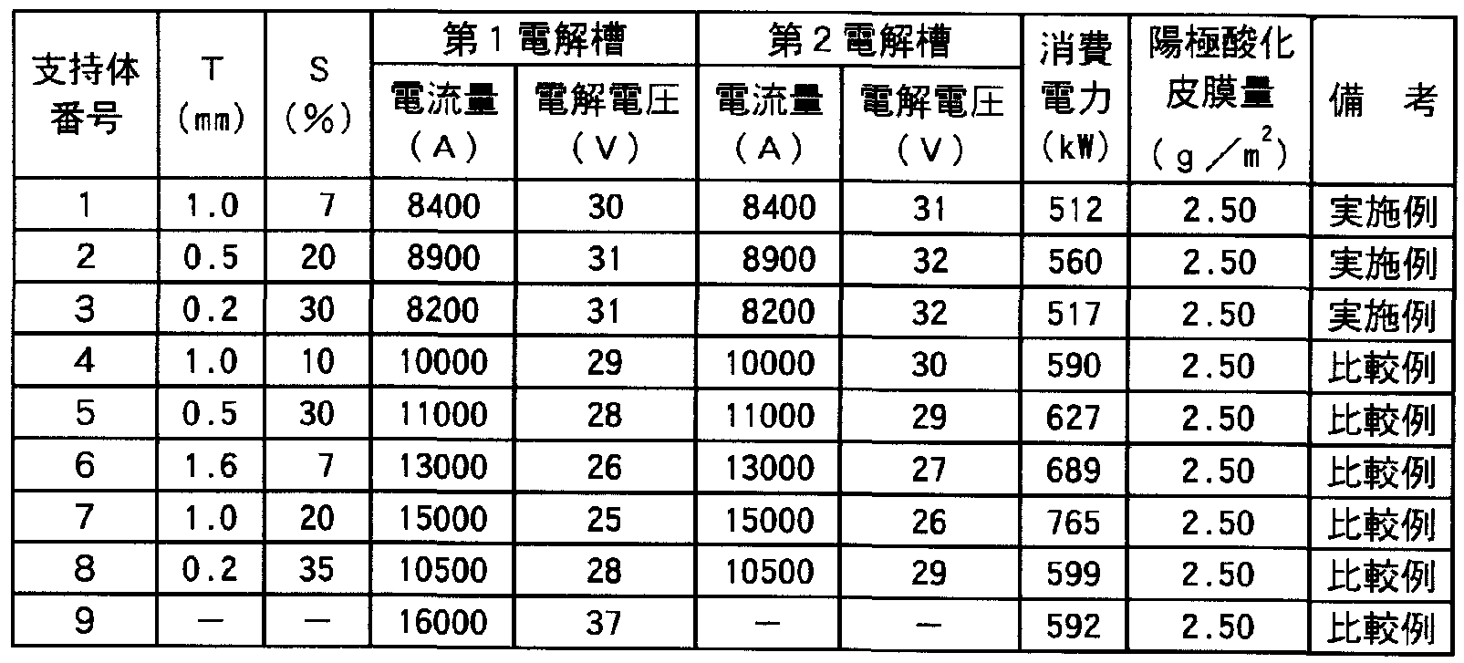
- Table 1 shows the electrolysis voltage for anodization.
- the anodizing treatment was performed in a 210 g ZL sulfuric acid aqueous solution at a temperature of 30 ° C.
- the ratio S (%) of the area of the energized portion to the area of the strip-shaped aluminum plate was adjusted.
- Table 1 shows the ratio S (%) of the area of the current-carrying portion to the area of the applied strip-shaped aluminum plate and the distance T (mm) between the strip-shaped aluminum plate and the electrical insulator.
- the distance between the strip-shaped aluminum plate and the anode was 50 mm.
- the support 9 was anodized under the electrolysis conditions shown in Table 1 using one tank of an anodizing tank (electrolytically treated portion 6 m) shown in FIG.
- the anodizing treatment was performed in a 210 g ZL sulfuric acid aqueous solution at a temperature of 30 ° C.
- Table 1 shows the amount of the anodized film formed.
- a positive photosensitive lithographic printing plate was produced by applying the following positive photosensitive composition on the above supports 1 to 9 so that the dry weight was 2 gZm 2 .
- Naphthoquinone (1, 2) -diazide (2) esterified product of 5-sulfoyl chloride and pyrogallol-aceton resin (weight average molecular weight 2500) (binding rate 20%)
- Methylseguchi sorb 200 parts The obtained photosensitive lithographic printing plate material was subjected to image exposure and development treatment to produce a printing plate, and printing was performed. In all cases, a good printed matter was obtained.
- the anodizing method of the present invention can form an anodized coating on an aluminum plate with reduced power loss.
Landscapes
- Chemical & Material Sciences (AREA)
- Chemical Kinetics & Catalysis (AREA)
- Electrochemistry (AREA)
- Printing Plates And Materials Therefor (AREA)
Abstract
帯状アルミニウム板を電解槽に含まれる電解液中で陽極酸化処理する方法であって、該電解液中で対向する陽極と陰極の間に帯状アルミニウム板を配置し、該陽極と該帯状アルミニウム板との間に通電部を有する電気絶縁体を配置し、該通電部は該帯状アルミニウム板の巾手方向長さに対して外側から35%の位置以内にあり、該帯状アルミニウム板の面積に対する該通電部の面積の割合S(%)と該帯状アルミニウム板と該電気絶縁体との距離T(mm)との関係が、5(%)≦S(%)≦30(%)かつ0.2≦T≦6×S-0.8であり、該通電部を通じて該陽極と該帯状アルミニウム板間に通電し、該帯状アルミニウム板の該陰極と対面する面に陽極酸化皮膜を形成することを特徴とする。電力ロスが少ない、帯状アルミニウム板の陽極酸化処理方法が提供できる。
Description
明 細 書
帯状アルミニウム板の陽極酸化処理方法、平版印刷版材料用支持体及 び陽極酸化処理装置
技術分野
[0001] 本発明はアルミニウム板面に陽極酸化膜を形成する陽極酸化処理方法、該陽極酸 化処理方法に用いられる陽極酸化処理装置及び該陽極酸化処理方法を用いて製 造された平版印刷版材料に用いられるアルミニウム支持体に関する。
背景技術
[0002] 平版印刷に用いられる平版印刷版の支持体としてアルミニウム板を用いることが知 られている。
[0003] 平版印刷版の支持体として用いられアルミニウム板としては、保水性、耐刷性など の印刷適性を付与するため、その表面に粗面化及び陽極酸ィ匕処理が施されたもの が広く用いられている。
[0004] 上記の陽極酸ィ匕処理する方法としては例えば、帯状金属板を電解液中で連続走 行させ、該金属板とこの一表面上に展開する電極との間に電流を流すことにより該金 属板を電解処理する方法にぉ 、て、該金属板の該電解処理が行なわれる領域にお ける該電極とは支持体の反対側の裏面側に電気絶縁板を直接配置して該電解処理 を行なうことを特徴とする帯状金属板の電解処理方法 (特許文献 1参照)、電解液中 を連続走行する帯状金属板の両面各側にそれぞれ電極を配置してなる電解処理装 置において、該帯状金属板の一面のみを電解しょうとする際には該帯状金属板と他 面側電極との間に電気絶縁材料を配置して両者の間に電流が流れることを抑制し、 該帯状金属板の両面を電解処理する際には該電気絶縁材料を前記の配置場所か ら移動させて該両面各側の両電極と該帯状金属板との間で電流が流れるようにし、 前記両態様を反復可能とする手段を設けたことを特徴とする帯状金属板の電解処理 装置を用いる方法 (特許文献 2参照)が知られて ヽる。
[0005] また、陽極と陰極の間に帯状被処理物を配置して陽極酸化皮膜を形成するする方 法、例えば、電解液が満たされている電解槽内において、(+ )の電気を加電する給
電電極と、(一)の電気が加電される電解電極を平行平面状に対極させ、同対極間を 通過する連続帯状の被処理物の進行方向に、上記対極に対して夫々スリット板をそ のスリット部と被処理物との間隙を数 mm以内に近接して配設して仕切ると共に、上 記スリット部力 連続して被処理物の両側端耳部に、先端溝部を上記耳部と被処理 物の厚さ方向の間隙を約 lmm程度、かつ端耳部への嵌り込みの深さを通板機能の 精度と関連して数 mm以内にしてマスクセパレーターを平面状に配置して被処理物 の表裏を別々に各電極の電場を囲むように区面せしめ、同区画部を電気的に独立さ せることにより上記被処理物内を流れる電解電流を表裏方向に流すことを特徴とする 直流電解による連続コイルアルマイトの片面専用処理装置を用いる方法 (特許文献 3 参照)が知られている。
[0006] し力しながら、これらの方法においても、まだ電力ロスが多ぐ効率的なアルミニウム 板の陽極酸化処理が求められて!/ヽた。
特許文献 1 :特開昭 57— 47894号公報
特許文献 2:特公昭 63 - 58233号公報
特許文献 3:特公昭 58 - 24517号公報
発明の開示
発明が解決しょうとする課題
[0007] 本発明の目的は、電力ロスの少ない、帯状アルミニウム板の陽極酸化処理方法、そ れに用いられる陽極酸化処理装置及び前記処理方法により得られる平版印刷版材 料用支持体を提供することにある。
課題を解決するための手段
[0008] 本発明の上記目的は、下記の構成により達成される。
1.帯状アルミニウム板を電解槽に含まれる電解液中で陽極酸化処理する方法であ つて、該電解液中で対向する陽極と陰極の間に帯状アルミニウム板を配置し、該陽 極と該帯状アルミニウム板との間に通電部を有する電気絶縁体を配置し、該通電部 は該帯状アルミニウム板の巾手方向長さに対して外側から 35%の位置以内にあり、 該帯状アルミニウム板の面積に対する該通電部の面積の割合 S (%)と該帯状アルミ ニゥム板と該電気絶縁体との距離 T(mm)との関係が、 5 (%)≤S (%)≤30 (%)か
つ 0. 2≤T≤6 X S— °·8であり、該通電部を通じて該陽極と該帯状アルミニウム板間に 通電し、該帯状アルミニウム板の該陰極と対面する面に陽極酸化皮膜を形成するこ とを特徴とする帯状アルミニウム板の陽極酸化処理方法。
2.前記帯状アルミニウム板を前記電解液中で前記陽極と前記陰極との間を長手方 向に走行させ、前記通電部が長手方向のスリット状開口部であることを特徴とする 1 に記載の帯状アルミニウム板の陽極酸化処理方法。
3.前記スリット状開口部の幅が、前記帯状アルミニウム板の幅の 5〜30%であること を特徴とする 2に記載の帯状アルミニウム板の陽極酸化処理方法。
4.前記スリット状開口部の幅が、前記帯状アルミニウム板の幅の 7〜20%であること を特徴とする 3に記載の帯状アルミニウム板の陽極酸化処理方法。
5.前記アルミニウム板を走行させる速度が 5〜: LOOmZ分であることを特徴とする 2 〜4のいずれか 1項に記載の帯状アルミニウム板の陽極酸ィ匕処理方法。
6.前記陽極酸化被膜の量が、 1. 5〜4gZm2であることを特徴とする 1〜5のいずれ 力 1項に記載の帯状アルミニウム板の陽極酸化処理方法。
7.前記陽極酸化被膜の量が、 2〜3gZm2であることを特徴とする 1〜5のいずれか 1項に記載の帯状アルミニウム板の陽極酸化処理方法。
8.前記帯状アルミニウム板と前記陽極との間の距離力 Omn!〜 60mmであることを 特徴とする 1〜7のいずれか 1項に記載の帯状アルミニウム板の陽極酸化処理方法。
9.前記帯状アルミニウム板の厚さが 0. 15mm〜0. 50mmであることを特徴とする 1 〜8のいずれか 1項に記載の帯状アルミニウム板の陽極酸ィ匕処理方法。
10.前記帯状アルミニウム板が平版印刷版材料用支持体であることを特徴とする 1〜 9のいずれか 1項に記載の帯状アルミニウム板の陽極酸ィヒ処理方法。
11. 10に記載の帯状アルミニウム板の陽極酸化処理方法により陽極酸化処理され たことを特徴とする平版印刷版材料用支持体。
12. 1〜: L0のいずれか 1項に記載の帯状アルミニウム板の陽極酸化処理方法に用 いられることを特徴とする陽極酸化処理装置。
発明の効果
本発明の上記構成により、電力ロスの少ない、帯状アルミニウム板の陽極酸化処理
方法、それに用いられる陽極酸化処理装置及び前記処理方法により得られる平版印 刷版材料用支持体が提供できる。
図面の簡単な説明
[0010] [図 1]図 1(a)は、本発明の陽極酸ィ匕処理装置の 1実施態様を示す側面図であり、図 1
(b)は、図 1(a)の陽極酸ィ匕処理装置の電解槽 (実施例で用いられている)の直線 A-A 'から見た断面図である。
[図 2]陽極酸ィ匕処理装置の平面図 (電解液 2を除いた場合の図)である。
[図 3]給電槽を有する従来の処理装置の 1例を示す側面図である。
[図 4]電気絶縁体の形状の例を示す平面図である。
符号の説明
[0011] 1 帯状アルミニウム板
2 電解液
3、 32 電解槽
4 ローラ
5 陽極
6 陰極
7 電気絶縁体
8 通電部
9、 9' 外側
10、 10' 外側から 35%の位置
21 電気供給手段
31 給電槽
発明を実施するための最良の形態
[0012] 本発明は、帯状アルミニウム板を電解槽に含まれる電解液中で陽極酸化処理する 方法であって、電解液中で対向する陽極と陰極の間に帯状アルミニウム板を配置し、 該陽極と該アルミニウム板との間に通電部を有する電気絶縁体を配置し、該通電部 は該帯状アルミニウム板の巾手方向長さに対して外側から 35%の位置以内にあり、 該帯状アルミニウム板の面積に対する該通電部の面積の割合 S (%)と該帯状アルミ
ニゥム板と該電気絶縁体との距離 T(mm)との関係が、 5 (%)≤S (%)≤30 (%)か つ 0. 2≤T≤6 X S— Q'8であり、該通電部を通じて該陽極と該帯状アルミニウム板間に 通電し、該帯状アルミニウム板の該陰極と対面する面に陽極酸化皮膜を形成するこ とを特徴とする。
[0013] (帯状アルミニウム板)
本発明に係る帯状アルミニウム板は、帯状のアルミニウム板であり、その材質として は純アルミニウム板またはアルミニウム合金板どちらも用いることができる。
[0014] アルミニウム合金としては、種々のものが使用でき、例えば、珪素、銅、マンガン、マ グネシゥム、クロム、亜鉛、鉛、ビスマス、ニッケル、チタン、ナトリウム、鉄等の金属と アルミニウムの合金が用いられ、各種圧延方法により製造されたアルミニウム板が使 用できる。
[0015] また、近年普及しつつあるスクラップ材およびリサイクル材などの再生アルミニウム 地金を圧延した再生アルミニウム板も使用できる。
[0016] (陽極酸化処理)
本発明に係る陽極酸化処理の前には粗面化処理 (砂目立て処理)を施すのが好ま しぐ粗面化するに先立って表面の圧延油を除去するために脱脂処理を施すことが 好ましい。
[0017] 脱脂処理としては、トリクレン、シンナー等の溶剤を用いる脱脂処理、ケシロン、トリ エタノール等のェマルジヨンを用いたェマルジヨン脱脂処理等が用いられる。又、脱 脂処理には、苛性ソーダ等のアルカリの水溶液を用いることもできる。脱脂処理に苛 性ソーダ等のアルカリ水溶液を用いた場合、上記脱脂処理のみでは除去できな 、汚 れゃ酸化皮膜も除去することができる。脱脂処理に苛性ソーダ等のアルカリ水溶液を 用いた場合、支持体の表面にはスマットが生成するので、この場合には、燐酸、硝酸 、硫酸等の酸、或いはそれらの混酸に浸漬しデスマット処理を施すことが好ましい。
[0018] 次いで粗面化処理が施される。粗面化の方法としては、例えば、機械的粗面化方 法、硝酸あるいは塩酸を主体とする電解による電解粗面化処理が挙げられる。
[0019] 機械的粗面化方法は特に限定されるものではな 、が、ブラシ研磨法、ホーユング 研磨法が好ましい。ブラシ研磨法による粗面化は、例えば、直径 0. 2〜0. 8mmのブ
ラシ毛を使用した回転ブラシを回転し、支持体表面に、例えば、粒径 10〜: LOO /z m の火山灰の粒子を水に均一に分散させたスラリーを供給しながら、ブラシを押し付け て行うことができる。ホーユング研磨による粗面化は、例えば、粒径 10〜100 μ mの 火山灰の粒子を水に均一に分散させ、ノズルより圧力をかけ射出し、支持体表面に 斜めから衝突させて粗面化を行うことができる。又、例えば、支持体表面に、粒径 10 〜100 /ζ πιの研磨剤粒子を、 100〜200 /ζ πιの間隔で、 2. 5 Χ 103〜10 X 103個/ cm2の密度で存在するように塗布したシートを張り合わせ、圧力をかけてシートの粗 面パターンを転写することにより粗面化を行うこともできる。
[0020] 上記の機械的粗面化法で粗面化した後は、支持体の表面に食い込んだ研磨剤、 形成されたアルミニウム屑等を取り除くため、酸又はアルカリの水溶液に浸漬すること が好ましい。酸としては、例えば、硫酸、過硫酸、弗酸、燐酸、硝酸、塩酸等が用いら れ、塩基としては、例えば水酸ィ匕ナトリウム、水酸ィ匕カリウム等が用いられる。これらの 中でも、水酸ィ匕ナトリウム等のアルカリ水溶液を用いるのが好ましい。表面のアルミ- ゥムの溶解量としては、 0. 5〜5g/m2が好ましい。アルカリ水溶液で浸漬処理を行 つた後、燐酸、硝酸、硫酸、クロム酸等の酸或いはそれらの混酸に浸漬し中和処理を 施すことが好ましい。
[0021] 硝酸を主体とする電解液 (以下、硝酸電解液ともいう)中で行われる電解粗面化処 理は、一般には、 1〜50ボルトの範囲の電圧を印加することによって行うことができる 力 10〜30ボルトの範囲から選ぶのが好ましい。電流密度は、 10〜200A/dm2の 範囲を用いることができる力 20〜: LOOAZdm2の範囲力も選ぶのが好ましい。電気 量は、 100〜2000c/dm2の範囲を用いることができるが、 300〜1500cZdm2の範 囲から選ぶのが好ましい。電気化学的粗面化法を行う温度は、 10〜50°Cの範囲を 用いることができるが、 15〜45°Cの範囲力 選ぶのが好ましい。電解液における硝 酸濃度は 0. 1〜5質量%が好ましい。電解液には、必要に応じて、硝酸塩、塩化物、 アミン類、アルデヒド類、燐酸、クロム酸、ホウ酸、酢酸、しゅう酸、アルミニウム塩等を カロえることができる。
[0022] 上記の硝酸電解液中で電解粗面化処理を施した後は、表面の酸ィ匕アルミニウム屑 等を取り除くため、酸又はアルカリの水溶液に浸漬することが好ましい。酸としては、
例えば、硫酸、過硫酸、弗酸、燐酸、硝酸、塩酸等が用いられ、塩基としては、例え ば、水酸化ナトリウム、水酸ィ匕カリウム等が用いられる。これらの中でもアルカリの水溶 液を用いるのが好ましい。表面のアルミニウムの溶解量としては、 0. l〜2g/m2が好 ましい。又、アルカリの水溶液で浸漬処理を行った後、燐酸、硝酸、硫酸、クロム酸等 の酸或いはそれらの混酸に浸漬し中和処理を施すことが好まし 、。
[0023] 塩酸を主体とする電解液 (以下、塩酸電解液とも!ヽぅ)中での電解粗面化処理は、 塩酸濃度は 5〜20gZlであり、好ましくは 6〜15gZlである。電流密度は 15〜200A Zdm2であり、好ましくは 20〜150AZdm2である。電気量は 400〜2000CZdm2で あり、好ましくは 500〜1500CZdm2である。周波数は 40〜150Hzの範囲で行うこと が好ましい。電解液の温度は、 10〜50°Cの範囲を用いることができるが、 15〜45°C の範囲力も選ぶのが好ましい。電解液には、必要に応じて、硝酸塩、塩化物、ァミン 類、アルデヒド類、燐酸、ホウ酸、酢酸、しゅう酸、アルミニウム塩等をカ卩えることができ る。
[0024] 上記の塩酸電解液中で電解粗面化処理を施した後は、表面の酸ィ匕アルミニウム屑 等を取り除くため、酸又はアルカリの水溶液に浸漬することが好ましい。酸としては、 例えば、硫酸、過硫酸、弗酸、燐酸、硝酸、塩酸等が用いられ、塩基としては、例え ば、水酸化ナトリウム、水酸ィ匕カリウム等が用いられる。これらの中でもアルカリの水溶 液を用いるのが好ましい。表面のアルミニウムの溶解量としては、 0. l〜2gZm2が好 ましい。又、アルカリの水溶液で浸漬処理を行った後、燐酸、硝酸、硫酸等の酸或い はそれらの混酸に浸漬し中和処理を施すことが好ましい。
[0025] 粗面化された表面の算術平均粗さ (Ra)は 0. 3〜0. 8 μ mが好ましぐ粗面化処理 での電解液濃度、電流密度、電気量などの条件の組み合わせで制御することが出来 る。
[0026] 本発明に係る陽極酸化処理方法は、上記のような粗面化の次に行われるのが好ま しい。
[0027] 本発明に係る陽極酸化処理方法を図により説明する。
[0028] 図 1(a)は、本発明の陽極酸化処理装置の 1実施態様を示す側面図であり、図 1 (b) は、図 1(a)の陽極酸ィ匕処理装置の電解槽 (後述の実施例で用いられている)の直線 A
-A'から見た断面図である。図 2は陽極酸ィ匕処理装置の平面図 (電解液 2を除いた場 合の図)である。
[0029] 図 3は給電槽を有する従来の処理装置の 1例を示す側面図である。
[0030] 図 4は電気絶縁体の形状の例を示す平面図である。
[0031] 図 1 (a)、 (b)において、帯状アルミニウム板 1は、電解液 2が満たされた電解槽 3の 中をローラ 4を介して搬送されて陽極酸化処理される。
[0032] 陽極 5及び陰極 6は電解液 2中で走行する帯状アルミニウム板 1を挟んで対向して 配置される。
[0033] 帯状アルミニウム板 1と陽極 5の間には図 1(b)に示されるような通電部 8を有する電 気絶縁体 7が配置される。本発明に係る通電部とは、電気絶縁体に設けられた開口 部を言う。
[0034] 帯状アルミニウム板 1を走行させつつ、陽極 5と陰極 6間に電圧 (電気供給手段 21 によって)をかけることにより通電部 8を通じて陽極 5から帯状アルミニウム板 1に電流 が流れ、さらに帯状アルミニウム板 1から陰極 6に電流が流れ、帯状アルミニウム板 1 の陰極 6と対面する面に陽極酸化皮膜を形成する。
[0035] 本発明に係る通電部 8は、帯状アルミニウム板 1の巾手方向長さに対して外側から
35%の位置以内にあることが必要である。
[0036] 上記外側とは、図 2に示すように帯状アルミニウム板 1の巾手方向両端部に相当す る位置 9及び^ である。
[0037] 巾手方向長さに対して 35%以内とはこの各々の外側から帯状アルミニウム板の巾 手方向の中心に向かって各々巾手長さ(帯状アルミニウム板の巾 100)に対して 35
%の長さ(図 2の 35)だけ内側に入った位置 10及び 10' の間にあることをいう。
[0038] 通電部 8即ち電気絶縁体 7に設けられた開口部の形状としては、長手方向に連続 するスリット状開口部であることが好ま 、。
[0039] このスリット状開口部の巾は、帯状アルミニウム板 1の全巾に対して 5〜30%である ことが好ましぐ特に 7〜20%であることが好ましい。
[0040] また、本発明にお 、ては、帯状アルミニウム板の面積に対する該通電部の面積の 割合 S (%)と該帯状アルミニウム板と該電気絶縁体との距離 T (mm)との関係が、 5 (
%)≤ S (%)≤ 30 (%)かつ 0. 2≤T≤ 6 X S— 08である。
[0041] 上記帯状アルミニウム板の面積に対する該通電部の面積の割合 S (%)とは、電解 槽内にお!/、て、対向する電気絶縁体が存在する部分の帯状アルミニウム版面積と通 電部の面積との和に対する、通電部の面積の割合をいう。
[0042] 電気絶縁体 7は電解液槽 3の壁と接触していることが好ましい。即ち電気絶縁体の 陽極部側の電解液と陰極部側の電解液は、通電部のみを通じて繋がって 、ることが 好ましい態様である。図 2において、番号 4はローラを表し、番号 6は陰極を表す。
[0043] また、帯状アルミニウム板と陽極との間の距離は、電力ロスの面から 20mm〜100 mmであることが好ましぐ特に 40〜60mmであることが好ましい。
[0044] 本発明においては、帯状アルミニウム板の厚さが 0. 15mm〜0. 50mmである場 合が好ましぐこの場合帯状アルミニウム板の表面上(陽極酸化皮膜を形成する表面 )に通電する電流密度としては 500〜10000AZm2が好ましい。
[0045] 帯状アルミニウム板を走行させる際の速さとしては、 5mZ分〜 lOOmZ分が好まし く、 10mZ分〜 80mZ分が特に好ましい。
[0046] 本発明に係る通電部即ち開口部の形状としては、図 4 (a)で示されるような巾手方 向の中心に直線で囲まれ、電気絶縁体中に設けられたスリット、図 4 (b)で示されるよ うな直線で囲まれ、電気絶縁体中に不連続に設けられたスリットであってもよいし、あ るいは、曲線に囲まれたスリット、電気絶縁体上の不連続な孔、編み目状の孔などの 開口部であってもよい。 図 4 (a)において、 "3"は電解槽、 "7"は電気絶縁体、 "8" は通電部を表す。 図 4 (b)において、 "3"は電解槽、 "7"は、電気絶縁体、 "8"は、 通電部を表す。
[0047] 本発明に係る電気絶縁体は、 1015 Ω以上の体積抵抗を有するものを! ヽ、例えば 、アクリル榭脂、ポリ塩化ビニル、ポリプロピレン、ポリブチレン、ポリエチレンポリスチ レンなどが挙げられる力 特に強度を兼ね備えたポリ塩ィ匕ビュルやポリプロピレンを 用いることが好ましい。
[0048] 本発明に用いられる電解槽は複数連続して設けられる方がより有効である。
[0049] また、上記開口通電部を通じて流れる電流密度としては、 500AZm2〜60000A /m2が好ましい。
[0050] 陽極の材料としては、 Tiのメッシュや、白金メッシュなどが用いられる。また、陰極の 材料としては、カーボンやアルミニウムを用いることができる。
[0051] これらは一体物でなくてもよぐ例えば、 50〜200mm長さの陽極を多数配置し、そ の間隙から、水素ガス等が陰極下面に溜まらな 、ようにすることが好ま 、。
[0052] 図 3において、前段に陽極 5を有する給電槽 31を配置し、後段に陰極 6を有する電 解槽 32を配置する。処理速度が速くなると大電流が必要になり、その場合は電源を
2台、 3台と分割して配置し、陰極をそれに応じて伸ばすことが必要になる。この場合
、アルミニウムが抵抗となり、所望の電流が取れない場合があるので、処理速度が速 くなるに従い、処理長さには限界があると推定される。
[0053] 本発明の陽極酸化処理に用いられる電解液としては、硫酸または硫酸を主体とす る電解液 (以下、硫酸電解液とも言う)を用いて行うのが好まし 、。
[0054] 硫酸の濃度は、 5〜50質量%が好ましぐ 15〜35質量%が特に好ましい。電解液 の温度は 10〜50°Cが好ましい。
[0055] 陽極酸化処理の処理電圧は 18V以上であることが好ましぐ 20V以上であることが 更に好ましい。
[0056] 本発明に係る平版印刷版材料用支持体の形成される陽極酸化皮膜量は、 1. 5〜
4gZm2が好ましぐ好ましくは 2〜3gZm2である。
[0057] 陽極酸化皮膜量は、例えばアルミニウム板を燐酸クロム酸溶液 (燐酸 85%液: 35m
1、無水クロム酸: 20gを 1Lの水に溶解して作製)に、 90°Cで 5分間浸漬し、酸化被膜 を溶解し、板の被覆溶解前後の質量変化測定等カゝら求められる。
[0058] 陽極酸ィ匕皮膜にはマイクロポアが生成される力 マイクロポアの密度は、 400〜70
0偶/ μ m2力好ましく、 400〜600偶/ μ m2力 ^更に好まし!/、。
[0059] 陽極酸化処理されたアルミニウム板は、必要に応じ封孔処理を施してもよい。これら 封孔処理は、熱水処理、沸騰水処理、水蒸気処理、珪酸ソーダ処理、重クロム酸塩 水溶液処理、亜硝酸塩処理、酢酸アンモニゥム処理、ポリビニルホスホン酸処理等 公知の方法を用いて行うことができる。
[0060] 本発明の陽極酸化処理方法は、上述の電解槽と、この電解槽に電気を供給するた めの手段とを、備えた陽極酸ィ匕処理装置を用いることにより行うことができる。
[0061] 本発明に係る平版印刷版材料用支持体の陽極酸化処理を施されたアルミニウム板 上に感光層を設け、感光性平版印刷版材料とすることができる。
[0062] 感光層は、画像露光により画像を形成し得るものであり、従来 PS版の感光層として 公知のポジ型、ネガ型の感光層を用いることができる。
[0063] (ポジ型感光層)
ポジ型感光層に用いられる感光性物質としては、例えば o ナフトキノンジアジドィ匕 合物が挙げられる。
[0064] o ナフトキノンジアジドィ匕合物としては、特公昭 43— 28403号公報に記載されて いる 1, 2—ジァゾナフトキノンスルホン酸とピロガロール 'アセトン榭脂とのエステルが 好ましい。その他の好適なオルトキノンジアジド化合物としては例えば、米国特許第 3 , 046, 120号および同第 3, 188, 210号明糸田書【こ記載されて!ヽる 1, 2 ジァ、ノナ フトキノンー5—スルホン酸とフエノール、ホルムアルデヒド榭脂とのエステルがあり、 特開平 2— 96163号公報、特開平 2— 96165号公報および特開平 2— 96761号公 報に記載されて 、る 1 , 2 ジァゾナフトキノン 4 スルホン酸とフエノール ホルム アルデヒド榭脂とのエステルがある。その方の有用な o ナフトキノンジアジドィ匕合物 としては、数多くの特許等で公知のものが挙げられる。例えば、特開昭 47— 5303号 、同 48— 63802号、同 48— 63803号、同 48— 96575号、同 49— 38701号、同 48 — 13854号、特公昭 37— 18015号、同 41— 11222号、同 45— 9610号、同 49— 17481号公報、米国特許第 2, 797, 213号、同第 3, 454, 400号、同第 3, 544, 3 23号、同第 3, 573, 917号、同第 3, 674, 495号、同第 3, 785, 825号、英国特許 第 1, 227, 602号、同第 1, 251, 345号、同第 1, 267, 005号、同第 1, 329, 888 号、同第 1, 330, 932号、ドイツ特許第 854, 890号などの各明細書中に記載され TV、るものを挙げることができる。
[0065] o キノンジアジドィ匕合物は単独でも感光層を構成することができる力 アルカリ水 に可溶な榭脂を結合剤 (バインダー)として併用することが好ましい。この様なアル力 リ水に可溶な榭脂としては、ノボラック型の樹脂があり、例えばフエノールホルムアル デヒド榭脂、 o—、 m—および p タレゾールホルムアルデヒド榭脂、 mZp 混合タレ ゾールホルムアルデヒド榭脂、フエノール Zタレゾール(o—、 m—、 p—、 mZp およ
び oZm—混合の 、ずれでもよ 、)混合ホルムアルデヒド榭脂などが挙げられる。また 、フエノール変性キシレン榭脂、ポリヒドロキシスチレン、ポリハロゲン化ヒドロキシスチ レン、特開昭 51— 34711号公報に開示されているようなフエノール性水酸基を含有 するアクリル系榭脂も用いることができる。その他の好適なノインダ一として、ノ ックコ ート層に添加する高分子化合物を形成するモノマーの例として挙げた前記(1)〜(1 2)に示すモノマー、および(13)アクリル酸、メタクリル酸、無水マレイン酸、ィタコン酸 などの不飽和カルボン酸をその構成単位とする通常 1万〜 20万の分子量を持つ共 重合体を挙げることができる。
[0066] また、上記のポジ型の感光層中には、現像条件に対する処理の安定性 ( 、わゆる 現像ラチチュード)を広げるため、特開昭 62— 251740号公報ゃ特開平 2— 96760 号公報、同 4— 68355号公報に記載されているような非イオン界面活性剤、特開昭 5 9— 121044号公報、特開平 4— 13149号公報に記載されているような両性界面活 性剤を添加することができる。
[0067] 非イオン界面活性剤の具体例としては、ソルビタントリステアレート、ソルビタンモノ パルミテート、ソルビタントリオレート、ステアリン酸モノグリセリド、ポリオキシエチレンソ ルビタンモノォレート、ポリオキシエチレンノユルフェ-ルエーテルなどが挙げられる。 両性界面活性剤の具体例としては、アルキルジ (アミノエチル)グリシン、アルキルポリ アミノエチルグリシン塩酸塩、 2—アルキル N、カルボキシェチルー N—ヒドロキシ ェチルイミダゾリ-ゥムベタインや N テトラデシルー N, N ベタイン型(例えば、商 品名ァモーゲン K、第一工業 (株)製)およびアルキルイミダゾリン系(例えば、商品名 レボン 15、三洋化成 (株)製)などが挙げられる。上記非イオン界面活性剤および両 性界面活性剤の感光性組成物中に占める割合は、 0. 05〜15質量%が好ましぐよ り好ましくは 0. 1〜5質量%でぁる。
[0068] 上記ポジ型感光層中には、露光後直ちに可視像を得るための焼き出し剤や、画像 着色剤としての染料や顔料を加えることができる。
[0069] 焼き出し剤としては、露光によって酸を放出する化合物 (光酸放出剤)と塩を形成し 得る有機染料の組合せを代表として挙げることができる。具体的には、特開昭 50— 3 6209号、同 53— 8128号の各公報に記載されている ο ナフトキノンジアジドー 4
スルホン酸ハロゲ -ドと塩形成性有機染料の組合せや、特開昭 53— 36223号、同 5 4— 74728号、同 60— 3626号、同 61— 143748号、同 61— 151644号および同 6 3— 58440号の各公報に記載されているトリハロメチルイ匕合物と塩形成性有機染料 の組合せを挙げることができる。力るトリハロメチルイ匕合物としては、ォキサゾール系 化合物とトリアジン系化合物とがあり、どちらも経時安定性に優れ、明瞭な焼き出し画 像を与える。画像の着色剤としては、前述の塩形成性有機染料以外に他の染料を用 いることができる。塩形成性有機染料も含めて、好適な染料として油溶性染料と塩基 性染料を挙げることができる。具体的には、オイルイェロー # 101、オイルイェロー # 103、オイルピンク # 312、オイルグリーン BG、オイルブルー BOS、オイルブルー # 603、オイルブラック BY、オイルブラック BS、オイルブラック T— 505 (以上、オリエン ト化学工業 (株)製)、ビクトリアピュアブルー、クリスタルバイオレット(C142555)、メ チルバイオレット(CI42535)、ェチルバイオレット、ローダミン B (CI145170B)、マラ カイトグリーン(C142000)、メチレンブルー(CI52015)などを挙げることができる。 また、特開昭 62 293247号公報に記載されて 、る染料は特に好ま U、。
[0070] (ネガ型感光層)
また、ネガ型感光層としては、感光性ジァゾィ匕合物を含む感光層、光重合性感光 層、光架橋性感光層などを有するものが挙げられる。
[0071] 感光性ジァゾィヒ合物としては、芳香族ジァゾ -ゥム塩と反応性カルボ-ル基含有有 機縮合剤、特にホルムアルデヒド、ァセトアルデヒドなどのアルデヒド類またはァセタ ール類とを酸性媒体中で縮合したジァゾ榭脂が好適に用いられる。その最も代表的 なものに P ジァゾフエ-ルァミンとホルムアルデヒドとの縮合物がある。これらのジァ ゾ榭脂の合成法は、例えば、米国特許第 2, 679, 498号、同第 3, 050, 502号、同 第 3, 311, 605号および同第 3, 277, 074号の明細書に記載されている。更に、感 光性ジァゾィ匕合物としては、特公昭 49 48, 001号公報記載の芳香族ジァゾ -ゥム 塩とジァゾ -ゥム基を含まない置換芳香族化合物との共縮合ジァゾィ匕合物が好適に 用いられ、中でもカルボキシル基や水酸基のようなアルカリ可溶基で置換された芳香 族化合物との共縮合ジァゾィ匕合物が好まし 、。本発明における感光性組成物中に は、先に示したポジ型感光性組成物と同様に、塗布面質を向上するための界面活性
剤を添加することができる。
[0072] (マット層)
感光層の表面には、真空焼き枠を用いた密着露光の際の真空引きの時間を短縮 し、且つ焼きボケを防ぐため、マット層を設けても良い。
[0073] 本発明に係る感光性平版印刷版材料の感光層としては、現像処理を特に必要とし な 、プロセスレス平版印刷版材料に使用される感熱画像形成層を用いることもできる
[0074] 本発明の平版印刷版材料用支持体を用いた感光性平版印刷版材料は画像露光 後必要に応じ現像処理が施され、平版印刷版として平版印刷に供することができる。 実施例
[0075] 以下、実施例を挙げて本発明を詳細に説明するが、本発明の態様はこれに限定さ れない。尚、実施例における「部」は、特に断りない限り「質量部」を表す。
[0076] (支持体 1〜13の作製)
0. 24mm厚、 JIS 1050のアルミニウム板 (板巾、 1000mm)を、連続して処理する 装置を用い、 5%水酸ィ匕ナトリウム水溶液中、 60°C、 10秒間、脱脂処理を行った後 水洗し、 10%硝酸水溶液中、 25°Cで 10秒間浸漬して中和した後、水洗した。
[0077] このアルミニウム板を、塩酸 llgZL、溶存アルミニウム 1. 5gZLの水溶液中で、温 度 30°C、電流密度 8kA/m2で 10秒間電解粗面化を行った後、 1%水酸化ナトリウ ム水溶液中で 20°C、 10秒間処理し、更に 10%硝酸水溶液中 25°Cで 10秒間浸漬し て中和した後、水洗した。
[0078] 上記電解粗面化されたアルミニウム板は、続いて、図 1に示すスリット形状の開口部 (以下、単にスリットと 1ヽぅ)を有する電気絶縁体を有する電解槽 (電解処理部分 3m)を 2槽 (第 1電解槽、第 2電解槽)を用いて、表 1に示す電解条件で陽極酸化処理された 。 (アルミニウム板は、第 1電解槽、続いて第 2電解槽を搬送された。 )
陽極酸化処理の電解電圧を表 1に示す。
[0079] 陽極酸化処理は、 210gZLの硫酸水溶液中、温度 30°Cで行われた。
[0080] 電気絶縁体のスリットの幅を変化させることにより、帯状アルミニウム板の面積に対 する通電部の面積の割合 S (%)は調整された。
[0081] 適用された帯状アルミニウム板の面積に対する通電部の面積の割合 S (%)と該帯 状アルミニウム板と該電気絶縁体との距離 T(mm)を表 1に示す。
[0082] 帯状アルミニウム板と陽極との距離は 50mmであった。
[0083] 続いて、水洗後、親水化処理として、 70°Cでポリビュルホスホン酸の 0. 2%水溶液 中に 30秒間浸潰し、水洗した。力べして、支持体 (平版印刷版材料用支持体) 1〜8 を得た。
[0084] 尚、支持体 9については、図 3に示す陽極酸化槽 (電解処理部分 6m) 1槽を使用し 、表 1に示す電解条件で陽極酸化処理を行った。陽極酸化処理は、 210gZLの硫 酸水溶液中、温度 30°Cで行われた。
[0085] 形成された陽極酸化被膜量を表 1に示す。
[0086] (ポジ型感光性平版印刷版の製造)
上記支持体 1〜9上に下記のポジ型感光性組成物を乾燥付き量が 2gZm2となるよ うに塗布して、ポジ型感光性平版印刷版を製造した。
[0087] ポジ型感光性組成物
ナフトキノン(1, 2)ージアジドー(2)— 5—スルホユルクロリドと、ピロガロールーァ セトン樹脂(重量平均分子量 2500)とのエステル化物(結合率 20%)
5部
フエノール: m -タレゾール: P—タレゾール =5 : 57: 38 (質量比)の混合フエノール 類とホルムアルデヒドとのノボラック榭脂(重量平均分子量 5500)
20部
ナフトキノン一(1, 2)—ジアジドー(2)—5—スルホユルクロリドと、 p— tert—ォクチ ルフエノールーホルムアルデヒドノボラック榭脂(重量平均分子量 1800)とのエステル 化物(結合率 50%) 0. 25部
3, 4ージメトキシ安息香酸 1. 25部
2—トリクロロメチル一 5— [ j8— (2—ベンゾフリル)ビュル]— 1, 3, 4—ォキサジァ ゾーノレ 0. 25咅
ビクトリアピュアブルー BOH (保土ケ谷ィ匕学社製) 0. 25部
メチルセ口ソルブ 200部
得られた感光性平版印刷版材料を画像露光、及び現像処理して、印刷版を作製し て、印刷を行ったところ、いずれも良好な印刷物が得られた。
[表 1]
Claims
[1] 帯状アルミニウム板を電解槽に含まれる電解液中で陽極酸化処理する方法であって
、該電解液中で対向する陽極と陰極の間に帯状アルミニウム板を配置し、該陽極と 該帯状アルミニウム板との間に通電部を有する電気絶縁体を配置し、該通電部は該 帯状アルミニウム板の巾手方向長さに対して外側から 35%の位置以内にあり、該帯 状アルミニウム板の面積に対する該通電部の面積の割合 S (%)と該帯状アルミニゥ ム板と該電気絶縁体との距離 T (mm)との関係が、 5 (%)≤S (%)≤30 (%)かつ 0. 2≤T≤6 X S— Q'8であり、該通電部を通じて該陽極と該帯状アルミニウム板間に通電し 、該帯状アルミニウム板の該陰極と対面する面に陽極酸ィ匕皮膜を形成することを特 徴とする帯状アルミニウム板の陽極酸化処理方法。
[2] 前記帯状アルミニウム板を前記電解液中で前記陽極と前記陰極との間を長手方向 に走行させ、前記通電部が長手方向のスリット状開口部であることを特徴とする請求 の範囲第 1項に記載の帯状アルミニウム板の陽極酸化処理方法。
[3] 前記スリット状開口部の幅が、前記帯状アルミニウム板の幅の 5〜30%であることを 特徴とする請求の範囲第 2項に記載の帯状アルミニウム板の陽極酸化処理方法。
[4] 前記スリット状開口部の幅が、前記帯状アルミニウム板の幅の 7〜20%であることを 特徴とする請求の範囲第 3項に記載の帯状アルミニウム板の陽極酸化処理方法。
[5] 前記アルミニウム板を走行させる速度が 5〜: LOOmZ分であることを特徴とする請求 の範囲第 2〜4項のいずれか 1項に記載の帯状アルミニウム板の陽極酸化処理方法
[6] 前記陽極酸化被膜の量が、 1. 5〜4g/m2であることを特徴とする請求の範囲第 1〜
5項のいずれか 1項に記載の帯状アルミニウム板の陽極酸ィヒ処理方法。
[7] 前記陽極酸化被膜の量が、 2〜3g/m2であることを特徴とする請求の範囲第 1〜5 項のいずれか 1項に記載の帯状アルミニウム板の陽極酸ィヒ処理方法。
[8] 前記帯状アルミニウム板と前記陽極との間の距離力 Omn!〜 60mmであることを特 徴とする請求の範囲第 1〜7項のいずれか 1項に記載の帯状アルミニウム板の陽極 酸化処理方法。
[9] 前記帯状アルミニウム板の厚さが 0. 15mn!〜 0. 50mmであることを特徴とする請求
の範囲第 1〜8項のいずれか 1項に記載の帯状アルミニウム板の陽極酸化処理方法
[10] 前記帯状アルミニウム板が平版印刷版材料用支持体であることを特徴とする請求の 範囲第 1〜9項のいずれか 1項に記載の帯状アルミニウム板の陽極酸ィヒ処理方法。
[11] 請求の範囲第 10項に記載の帯状アルミニウム板の陽極酸化処理方法により陽極酸 化処理されたことを特徴とする平版印刷版材料用支持体。
[12] 請求の範囲第 1〜10項のいずれか 1項に記載の帯状アルミニウム板の陽極酸ィ匕処 理方法に用いられることを特徴とする陽極酸化処理装置。
Priority Applications (1)
| Application Number | Priority Date | Filing Date | Title |
|---|---|---|---|
| JP2007508099A JPWO2006098227A1 (ja) | 2005-03-14 | 2006-03-10 | 帯状アルミニウム板の陽極酸化処理方法、平版印刷版材料用支持体及び陽極酸化処理装置 |
Applications Claiming Priority (2)
| Application Number | Priority Date | Filing Date | Title |
|---|---|---|---|
| JP2005070721 | 2005-03-14 | ||
| JP2005-070721 | 2005-03-14 |
Publications (1)
| Publication Number | Publication Date |
|---|---|
| WO2006098227A1 true WO2006098227A1 (ja) | 2006-09-21 |
Family
ID=36969443
Family Applications (1)
| Application Number | Title | Priority Date | Filing Date |
|---|---|---|---|
| PCT/JP2006/304686 Ceased WO2006098227A1 (ja) | 2005-03-14 | 2006-03-10 | 帯状アルミニウム板の陽極酸化処理方法、平版印刷版材料用支持体及び陽極酸化処理装置 |
Country Status (4)
| Country | Link |
|---|---|
| US (1) | US20060201359A1 (ja) |
| JP (1) | JPWO2006098227A1 (ja) |
| CN (1) | CN101137773A (ja) |
| WO (1) | WO2006098227A1 (ja) |
Families Citing this family (6)
| Publication number | Priority date | Publication date | Assignee | Title |
|---|---|---|---|---|
| JP2009221571A (ja) * | 2008-03-18 | 2009-10-01 | Fujifilm Corp | 電解処理装置および電解処理方法 |
| KR100892995B1 (ko) * | 2008-10-20 | 2009-04-10 | 손치호 | 금속의 아노다이징 처리 방법 및 그 시스템 |
| JP5389769B2 (ja) * | 2010-11-04 | 2014-01-15 | 有限会社 みさとみらい二十一 | 無端帯状印刷プレートを用いた印刷装置およびその印刷方法ならびに帯状印刷プレートの取付方法 |
| CN108374189A (zh) * | 2018-04-23 | 2018-08-07 | 青田温溪春桓铝氧化加工厂 | 铝氧化加工用自动化生产线 |
| CN108374188A (zh) * | 2018-04-23 | 2018-08-07 | 青田温溪春桓铝氧化加工厂 | 铝氧化加工用循环节能恒温处理设备 |
| CN111434807A (zh) * | 2019-01-15 | 2020-07-21 | 广东长盈精密技术有限公司 | 铝合金材料的表面处理方法及其应用 |
Citations (1)
| Publication number | Priority date | Publication date | Assignee | Title |
|---|---|---|---|---|
| JPS4925544B1 (ja) * | 1969-06-19 | 1974-07-01 |
Family Cites Families (2)
| Publication number | Priority date | Publication date | Assignee | Title |
|---|---|---|---|---|
| US3975242A (en) * | 1972-11-28 | 1976-08-17 | Nippon Steel Corporation | Horizontal rectilinear type metal-electroplating method |
| JP3340588B2 (ja) * | 1995-05-18 | 2002-11-05 | 松下電器産業株式会社 | アルミニウム電解コンデンサ用電極箔の製造装置及びその製造方法 |
-
2006
- 2006-03-09 US US11/371,016 patent/US20060201359A1/en not_active Abandoned
- 2006-03-10 CN CNA2006800076381A patent/CN101137773A/zh active Pending
- 2006-03-10 WO PCT/JP2006/304686 patent/WO2006098227A1/ja not_active Ceased
- 2006-03-10 JP JP2007508099A patent/JPWO2006098227A1/ja not_active Withdrawn
Patent Citations (1)
| Publication number | Priority date | Publication date | Assignee | Title |
|---|---|---|---|---|
| JPS4925544B1 (ja) * | 1969-06-19 | 1974-07-01 |
Also Published As
| Publication number | Publication date |
|---|---|
| CN101137773A (zh) | 2008-03-05 |
| US20060201359A1 (en) | 2006-09-14 |
| JPWO2006098227A1 (ja) | 2008-08-21 |
Similar Documents
| Publication | Publication Date | Title |
|---|---|---|
| JP2008111142A (ja) | 平版印刷版用アルミニウム合金板および平版印刷版用支持体 | |
| JP4410714B2 (ja) | 平版印刷版用支持体の製造方法 | |
| WO2006098227A1 (ja) | 帯状アルミニウム板の陽極酸化処理方法、平版印刷版材料用支持体及び陽極酸化処理装置 | |
| JP4250490B2 (ja) | 平版印刷版用アルミニウム合金素板および平版印刷版用支持体 | |
| US20060223005A1 (en) | Lithographic printing plate support and presensitized plate | |
| US20080311510A1 (en) | Lithographic printing plate support and presensitized plate | |
| JP2005265501A (ja) | 水溶液中のフッ素化合物およびリン酸化合物の濃度測定方法 | |
| JP2007070694A (ja) | 帯状アルミニウム板の陽極酸化処理方法、平版印刷版材料用支持体及び陽極酸化処理装置 | |
| JP4445762B2 (ja) | 平版印刷版用支持体の製造方法 | |
| JP2006076104A (ja) | 平版印刷版用支持体の製造方法 | |
| JP2006082387A (ja) | 平版印刷版用支持体の製造方法 | |
| JP4648057B2 (ja) | 平版印刷版用支持体の製造方法 | |
| JP2005088224A (ja) | 平版印刷版用アルミニウム板および平版印刷版用支持体 | |
| JP4268542B2 (ja) | 平版印刷版用支持体の製造方法 | |
| JP2006076105A (ja) | 平版印刷版用支持体の製造方法 | |
| JP4510570B2 (ja) | 平版印刷版用支持体の製造方法 | |
| JP4643380B2 (ja) | 平版印刷版用支持体の製造方法 | |
| JP2005001356A (ja) | 平版印刷版用支持体の製造方法 | |
| JP2006021425A (ja) | 平版印刷版用支持体の製造方法 | |
| JP2006240116A (ja) | 平版印刷版用支持体およびその製造方法 | |
| JP2004249728A (ja) | 平版印刷版用支持体および平版印刷版 | |
| JP2005047070A (ja) | 平版印刷版用支持体の製造方法 | |
| JP2005047084A (ja) | 平版印刷版用支持体の製造方法 | |
| JP2004268517A (ja) | 平版印刷版支持体の製造方法 | |
| JP2002082427A (ja) | 平版印刷版 |
Legal Events
| Date | Code | Title | Description |
|---|---|---|---|
| WWE | Wipo information: entry into national phase |
Ref document number: 200680007638.1 Country of ref document: CN |
|
| 121 | Ep: the epo has been informed by wipo that ep was designated in this application | ||
| WWE | Wipo information: entry into national phase |
Ref document number: 2007508099 Country of ref document: JP |
|
| NENP | Non-entry into the national phase |
Ref country code: DE |
|
| NENP | Non-entry into the national phase |
Ref country code: RU |
|
| 122 | Ep: pct application non-entry in european phase |
Ref document number: 06715506 Country of ref document: EP Kind code of ref document: A1 |