WO2002014244A1 - Hydrocarbon compound, material for organic electroluminescent element and organic electroluminescent element - Google Patents
Hydrocarbon compound, material for organic electroluminescent element and organic electroluminescent element Download PDFInfo
- Publication number
- WO2002014244A1 WO2002014244A1 PCT/JP2001/006920 JP0106920W WO0214244A1 WO 2002014244 A1 WO2002014244 A1 WO 2002014244A1 JP 0106920 W JP0106920 W JP 0106920W WO 0214244 A1 WO0214244 A1 WO 0214244A1
- Authority
- WO
- WIPO (PCT)
- Prior art keywords
- group
- compound
- substituted
- unsubstituted
- branched
- Prior art date
Links
Classifications
-
- C—CHEMISTRY; METALLURGY
- C07—ORGANIC CHEMISTRY
- C07D—HETEROCYCLIC COMPOUNDS
- C07D213/00—Heterocyclic compounds containing six-membered rings, not condensed with other rings, with one nitrogen atom as the only ring hetero atom and three or more double bonds between ring members or between ring members and non-ring members
- C07D213/02—Heterocyclic compounds containing six-membered rings, not condensed with other rings, with one nitrogen atom as the only ring hetero atom and three or more double bonds between ring members or between ring members and non-ring members having three double bonds between ring members or between ring members and non-ring members
- C07D213/04—Heterocyclic compounds containing six-membered rings, not condensed with other rings, with one nitrogen atom as the only ring hetero atom and three or more double bonds between ring members or between ring members and non-ring members having three double bonds between ring members or between ring members and non-ring members having no bond between the ring nitrogen atom and a non-ring member or having only hydrogen or carbon atoms directly attached to the ring nitrogen atom
- C07D213/06—Heterocyclic compounds containing six-membered rings, not condensed with other rings, with one nitrogen atom as the only ring hetero atom and three or more double bonds between ring members or between ring members and non-ring members having three double bonds between ring members or between ring members and non-ring members having no bond between the ring nitrogen atom and a non-ring member or having only hydrogen or carbon atoms directly attached to the ring nitrogen atom containing only hydrogen and carbon atoms in addition to the ring nitrogen atom
-
- C—CHEMISTRY; METALLURGY
- C07—ORGANIC CHEMISTRY
- C07C—ACYCLIC OR CARBOCYCLIC COMPOUNDS
- C07C13/00—Cyclic hydrocarbons containing rings other than, or in addition to, six-membered aromatic rings
- C07C13/28—Polycyclic hydrocarbons or acyclic hydrocarbon derivatives thereof
- C07C13/32—Polycyclic hydrocarbons or acyclic hydrocarbon derivatives thereof with condensed rings
- C07C13/54—Polycyclic hydrocarbons or acyclic hydrocarbon derivatives thereof with condensed rings with three condensed rings
- C07C13/547—Polycyclic hydrocarbons or acyclic hydrocarbon derivatives thereof with condensed rings with three condensed rings at least one ring not being six-membered, the other rings being at the most six-membered
- C07C13/567—Polycyclic hydrocarbons or acyclic hydrocarbon derivatives thereof with condensed rings with three condensed rings at least one ring not being six-membered, the other rings being at the most six-membered with a fluorene or hydrogenated fluorene ring system
-
- C—CHEMISTRY; METALLURGY
- C07—ORGANIC CHEMISTRY
- C07C—ACYCLIC OR CARBOCYCLIC COMPOUNDS
- C07C211/00—Compounds containing amino groups bound to a carbon skeleton
- C07C211/43—Compounds containing amino groups bound to a carbon skeleton having amino groups bound to carbon atoms of six-membered aromatic rings of the carbon skeleton
- C07C211/44—Compounds containing amino groups bound to a carbon skeleton having amino groups bound to carbon atoms of six-membered aromatic rings of the carbon skeleton having amino groups bound to only one six-membered aromatic ring
- C07C211/49—Compounds containing amino groups bound to a carbon skeleton having amino groups bound to carbon atoms of six-membered aromatic rings of the carbon skeleton having amino groups bound to only one six-membered aromatic ring having at least two amino groups bound to the carbon skeleton
- C07C211/50—Compounds containing amino groups bound to a carbon skeleton having amino groups bound to carbon atoms of six-membered aromatic rings of the carbon skeleton having amino groups bound to only one six-membered aromatic ring having at least two amino groups bound to the carbon skeleton with at least two amino groups bound to carbon atoms of six-membered aromatic rings of the carbon skeleton
-
- C—CHEMISTRY; METALLURGY
- C07—ORGANIC CHEMISTRY
- C07C—ACYCLIC OR CARBOCYCLIC COMPOUNDS
- C07C211/00—Compounds containing amino groups bound to a carbon skeleton
- C07C211/43—Compounds containing amino groups bound to a carbon skeleton having amino groups bound to carbon atoms of six-membered aromatic rings of the carbon skeleton
- C07C211/54—Compounds containing amino groups bound to a carbon skeleton having amino groups bound to carbon atoms of six-membered aromatic rings of the carbon skeleton having amino groups bound to two or three six-membered aromatic rings
-
- C—CHEMISTRY; METALLURGY
- C07—ORGANIC CHEMISTRY
- C07C—ACYCLIC OR CARBOCYCLIC COMPOUNDS
- C07C211/00—Compounds containing amino groups bound to a carbon skeleton
- C07C211/43—Compounds containing amino groups bound to a carbon skeleton having amino groups bound to carbon atoms of six-membered aromatic rings of the carbon skeleton
- C07C211/57—Compounds containing amino groups bound to a carbon skeleton having amino groups bound to carbon atoms of six-membered aromatic rings of the carbon skeleton having amino groups bound to carbon atoms of six-membered aromatic rings being part of condensed ring systems of the carbon skeleton
- C07C211/61—Compounds containing amino groups bound to a carbon skeleton having amino groups bound to carbon atoms of six-membered aromatic rings of the carbon skeleton having amino groups bound to carbon atoms of six-membered aromatic rings being part of condensed ring systems of the carbon skeleton with at least one of the condensed ring systems formed by three or more rings
-
- C—CHEMISTRY; METALLURGY
- C07—ORGANIC CHEMISTRY
- C07C—ACYCLIC OR CARBOCYCLIC COMPOUNDS
- C07C25/00—Compounds containing at least one halogen atom bound to a six-membered aromatic ring
- C07C25/18—Polycyclic aromatic halogenated hydrocarbons
- C07C25/22—Polycyclic aromatic halogenated hydrocarbons with condensed rings
-
- C—CHEMISTRY; METALLURGY
- C07—ORGANIC CHEMISTRY
- C07C—ACYCLIC OR CARBOCYCLIC COMPOUNDS
- C07C43/00—Ethers; Compounds having groups, groups or groups
- C07C43/02—Ethers
- C07C43/20—Ethers having an ether-oxygen atom bound to a carbon atom of a six-membered aromatic ring
- C07C43/21—Ethers having an ether-oxygen atom bound to a carbon atom of a six-membered aromatic ring containing rings other than six-membered aromatic rings
-
- C—CHEMISTRY; METALLURGY
- C07—ORGANIC CHEMISTRY
- C07D—HETEROCYCLIC COMPOUNDS
- C07D215/00—Heterocyclic compounds containing quinoline or hydrogenated quinoline ring systems
- C07D215/02—Heterocyclic compounds containing quinoline or hydrogenated quinoline ring systems having no bond between the ring nitrogen atom and a non-ring member or having only hydrogen atoms or carbon atoms directly attached to the ring nitrogen atom
- C07D215/12—Heterocyclic compounds containing quinoline or hydrogenated quinoline ring systems having no bond between the ring nitrogen atom and a non-ring member or having only hydrogen atoms or carbon atoms directly attached to the ring nitrogen atom with substituted hydrocarbon radicals attached to ring carbon atoms
-
- C—CHEMISTRY; METALLURGY
- C07—ORGANIC CHEMISTRY
- C07D—HETEROCYCLIC COMPOUNDS
- C07D333/00—Heterocyclic compounds containing five-membered rings having one sulfur atom as the only ring hetero atom
- C07D333/02—Heterocyclic compounds containing five-membered rings having one sulfur atom as the only ring hetero atom not condensed with other rings
- C07D333/04—Heterocyclic compounds containing five-membered rings having one sulfur atom as the only ring hetero atom not condensed with other rings not substituted on the ring sulphur atom
- C07D333/06—Heterocyclic compounds containing five-membered rings having one sulfur atom as the only ring hetero atom not condensed with other rings not substituted on the ring sulphur atom with only hydrogen atoms, hydrocarbon or substituted hydrocarbon radicals, directly attached to the ring carbon atoms
- C07D333/14—Radicals substituted by singly bound hetero atoms other than halogen
- C07D333/18—Radicals substituted by singly bound hetero atoms other than halogen by sulfur atoms
-
- C—CHEMISTRY; METALLURGY
- C09—DYES; PAINTS; POLISHES; NATURAL RESINS; ADHESIVES; COMPOSITIONS NOT OTHERWISE PROVIDED FOR; APPLICATIONS OF MATERIALS NOT OTHERWISE PROVIDED FOR
- C09K—MATERIALS FOR MISCELLANEOUS APPLICATIONS, NOT PROVIDED FOR ELSEWHERE
- C09K11/00—Luminescent, e.g. electroluminescent, chemiluminescent materials
- C09K11/06—Luminescent, e.g. electroluminescent, chemiluminescent materials containing organic luminescent materials
-
- H—ELECTRICITY
- H05—ELECTRIC TECHNIQUES NOT OTHERWISE PROVIDED FOR
- H05B—ELECTRIC HEATING; ELECTRIC LIGHT SOURCES NOT OTHERWISE PROVIDED FOR; CIRCUIT ARRANGEMENTS FOR ELECTRIC LIGHT SOURCES, IN GENERAL
- H05B33/00—Electroluminescent light sources
- H05B33/12—Light sources with substantially two-dimensional radiating surfaces
- H05B33/14—Light sources with substantially two-dimensional radiating surfaces characterised by the chemical or physical composition or the arrangement of the electroluminescent material, or by the simultaneous addition of the electroluminescent material in or onto the light source
-
- H—ELECTRICITY
- H05—ELECTRIC TECHNIQUES NOT OTHERWISE PROVIDED FOR
- H05B—ELECTRIC HEATING; ELECTRIC LIGHT SOURCES NOT OTHERWISE PROVIDED FOR; CIRCUIT ARRANGEMENTS FOR ELECTRIC LIGHT SOURCES, IN GENERAL
- H05B33/00—Electroluminescent light sources
- H05B33/12—Light sources with substantially two-dimensional radiating surfaces
- H05B33/20—Light sources with substantially two-dimensional radiating surfaces characterised by the chemical or physical composition or the arrangement of the material in which the electroluminescent material is embedded
-
- H—ELECTRICITY
- H10—SEMICONDUCTOR DEVICES; ELECTRIC SOLID-STATE DEVICES NOT OTHERWISE PROVIDED FOR
- H10K—ORGANIC ELECTRIC SOLID-STATE DEVICES
- H10K85/00—Organic materials used in the body or electrodes of devices covered by this subclass
- H10K85/60—Organic compounds having low molecular weight
- H10K85/615—Polycyclic condensed aromatic hydrocarbons, e.g. anthracene
- H10K85/626—Polycyclic condensed aromatic hydrocarbons, e.g. anthracene containing more than one polycyclic condensed aromatic rings, e.g. bis-anthracene
-
- H—ELECTRICITY
- H10—SEMICONDUCTOR DEVICES; ELECTRIC SOLID-STATE DEVICES NOT OTHERWISE PROVIDED FOR
- H10K—ORGANIC ELECTRIC SOLID-STATE DEVICES
- H10K85/00—Organic materials used in the body or electrodes of devices covered by this subclass
- H10K85/60—Organic compounds having low molecular weight
- H10K85/631—Amine compounds having at least two aryl rest on at least one amine-nitrogen atom, e.g. triphenylamine
- H10K85/633—Amine compounds having at least two aryl rest on at least one amine-nitrogen atom, e.g. triphenylamine comprising polycyclic condensed aromatic hydrocarbons as substituents on the nitrogen atom
-
- H—ELECTRICITY
- H10—SEMICONDUCTOR DEVICES; ELECTRIC SOLID-STATE DEVICES NOT OTHERWISE PROVIDED FOR
- H10K—ORGANIC ELECTRIC SOLID-STATE DEVICES
- H10K85/00—Organic materials used in the body or electrodes of devices covered by this subclass
- H10K85/60—Organic compounds having low molecular weight
- H10K85/649—Aromatic compounds comprising a hetero atom
- H10K85/654—Aromatic compounds comprising a hetero atom comprising only nitrogen as heteroatom
-
- C—CHEMISTRY; METALLURGY
- C07—ORGANIC CHEMISTRY
- C07C—ACYCLIC OR CARBOCYCLIC COMPOUNDS
- C07C2603/00—Systems containing at least three condensed rings
- C07C2603/02—Ortho- or ortho- and peri-condensed systems
- C07C2603/04—Ortho- or ortho- and peri-condensed systems containing three rings
- C07C2603/06—Ortho- or ortho- and peri-condensed systems containing three rings containing at least one ring with less than six ring members
- C07C2603/10—Ortho- or ortho- and peri-condensed systems containing three rings containing at least one ring with less than six ring members containing five-membered rings
- C07C2603/12—Ortho- or ortho- and peri-condensed systems containing three rings containing at least one ring with less than six ring members containing five-membered rings only one five-membered ring
- C07C2603/18—Fluorenes; Hydrogenated fluorenes
-
- C—CHEMISTRY; METALLURGY
- C07—ORGANIC CHEMISTRY
- C07C—ACYCLIC OR CARBOCYCLIC COMPOUNDS
- C07C2603/00—Systems containing at least three condensed rings
- C07C2603/02—Ortho- or ortho- and peri-condensed systems
- C07C2603/04—Ortho- or ortho- and peri-condensed systems containing three rings
- C07C2603/22—Ortho- or ortho- and peri-condensed systems containing three rings containing only six-membered rings
- C07C2603/24—Anthracenes; Hydrogenated anthracenes
-
- C—CHEMISTRY; METALLURGY
- C09—DYES; PAINTS; POLISHES; NATURAL RESINS; ADHESIVES; COMPOSITIONS NOT OTHERWISE PROVIDED FOR; APPLICATIONS OF MATERIALS NOT OTHERWISE PROVIDED FOR
- C09K—MATERIALS FOR MISCELLANEOUS APPLICATIONS, NOT PROVIDED FOR ELSEWHERE
- C09K2211/00—Chemical nature of organic luminescent or tenebrescent compounds
- C09K2211/10—Non-macromolecular compounds
- C09K2211/1003—Carbocyclic compounds
- C09K2211/1007—Non-condensed systems
-
- C—CHEMISTRY; METALLURGY
- C09—DYES; PAINTS; POLISHES; NATURAL RESINS; ADHESIVES; COMPOSITIONS NOT OTHERWISE PROVIDED FOR; APPLICATIONS OF MATERIALS NOT OTHERWISE PROVIDED FOR
- C09K—MATERIALS FOR MISCELLANEOUS APPLICATIONS, NOT PROVIDED FOR ELSEWHERE
- C09K2211/00—Chemical nature of organic luminescent or tenebrescent compounds
- C09K2211/10—Non-macromolecular compounds
- C09K2211/1003—Carbocyclic compounds
- C09K2211/1011—Condensed systems
-
- C—CHEMISTRY; METALLURGY
- C09—DYES; PAINTS; POLISHES; NATURAL RESINS; ADHESIVES; COMPOSITIONS NOT OTHERWISE PROVIDED FOR; APPLICATIONS OF MATERIALS NOT OTHERWISE PROVIDED FOR
- C09K—MATERIALS FOR MISCELLANEOUS APPLICATIONS, NOT PROVIDED FOR ELSEWHERE
- C09K2211/00—Chemical nature of organic luminescent or tenebrescent compounds
- C09K2211/10—Non-macromolecular compounds
- C09K2211/1003—Carbocyclic compounds
- C09K2211/1014—Carbocyclic compounds bridged by heteroatoms, e.g. N, P, Si or B
-
- C—CHEMISTRY; METALLURGY
- C09—DYES; PAINTS; POLISHES; NATURAL RESINS; ADHESIVES; COMPOSITIONS NOT OTHERWISE PROVIDED FOR; APPLICATIONS OF MATERIALS NOT OTHERWISE PROVIDED FOR
- C09K—MATERIALS FOR MISCELLANEOUS APPLICATIONS, NOT PROVIDED FOR ELSEWHERE
- C09K2211/00—Chemical nature of organic luminescent or tenebrescent compounds
- C09K2211/10—Non-macromolecular compounds
- C09K2211/1018—Heterocyclic compounds
- C09K2211/1025—Heterocyclic compounds characterised by ligands
- C09K2211/1029—Heterocyclic compounds characterised by ligands containing one nitrogen atom as the heteroatom
-
- C—CHEMISTRY; METALLURGY
- C09—DYES; PAINTS; POLISHES; NATURAL RESINS; ADHESIVES; COMPOSITIONS NOT OTHERWISE PROVIDED FOR; APPLICATIONS OF MATERIALS NOT OTHERWISE PROVIDED FOR
- C09K—MATERIALS FOR MISCELLANEOUS APPLICATIONS, NOT PROVIDED FOR ELSEWHERE
- C09K2211/00—Chemical nature of organic luminescent or tenebrescent compounds
- C09K2211/10—Non-macromolecular compounds
- C09K2211/1018—Heterocyclic compounds
- C09K2211/1025—Heterocyclic compounds characterised by ligands
- C09K2211/1092—Heterocyclic compounds characterised by ligands containing sulfur as the only heteroatom
-
- H—ELECTRICITY
- H10—SEMICONDUCTOR DEVICES; ELECTRIC SOLID-STATE DEVICES NOT OTHERWISE PROVIDED FOR
- H10K—ORGANIC ELECTRIC SOLID-STATE DEVICES
- H10K50/00—Organic light-emitting devices
- H10K50/10—OLEDs or polymer light-emitting diodes [PLED]
- H10K50/11—OLEDs or polymer light-emitting diodes [PLED] characterised by the electroluminescent [EL] layers
-
- H—ELECTRICITY
- H10—SEMICONDUCTOR DEVICES; ELECTRIC SOLID-STATE DEVICES NOT OTHERWISE PROVIDED FOR
- H10K—ORGANIC ELECTRIC SOLID-STATE DEVICES
- H10K85/00—Organic materials used in the body or electrodes of devices covered by this subclass
- H10K85/30—Coordination compounds
- H10K85/321—Metal complexes comprising a group IIIA element, e.g. Tris (8-hydroxyquinoline) gallium [Gaq3]
- H10K85/324—Metal complexes comprising a group IIIA element, e.g. Tris (8-hydroxyquinoline) gallium [Gaq3] comprising aluminium, e.g. Alq3
-
- Y—GENERAL TAGGING OF NEW TECHNOLOGICAL DEVELOPMENTS; GENERAL TAGGING OF CROSS-SECTIONAL TECHNOLOGIES SPANNING OVER SEVERAL SECTIONS OF THE IPC; TECHNICAL SUBJECTS COVERED BY FORMER USPC CROSS-REFERENCE ART COLLECTIONS [XRACs] AND DIGESTS
- Y10—TECHNICAL SUBJECTS COVERED BY FORMER USPC
- Y10S—TECHNICAL SUBJECTS COVERED BY FORMER USPC CROSS-REFERENCE ART COLLECTIONS [XRACs] AND DIGESTS
- Y10S428/00—Stock material or miscellaneous articles
- Y10S428/917—Electroluminescent
Definitions
- the present invention relates to an organic electroluminescent device, a material for an organic electroluminescent device that can be suitably used for the light-emitting device, and a novel hydrocarbon compound.
- an inorganic electroluminescent element has been used as a panel-type light source such as a backlight, but a high AC voltage is required to drive the light-emitting element.
- organic electroluminescent device organic electroluminescent device: organic EL device
- An organic electroluminescent element has a structure in which a thin film containing a compound having a light emitting function is sandwiched between a positive electrode and a negative electrode, and electrons and holes are injected into the thin film and recombined. An element that generates excitons and uses light emitted when these excitons are deactivated.
- the organic electroluminescent device can emit light at a low DC voltage of about several volts to several tens of volts, and has various colors (for example, red, blue, and green) by selecting the type of the fluorescent organic compound. (Color).
- Organic electroluminescent devices having such characteristics are expected to be applied to various light-emitting devices, display devices, and the like. However, in general, the luminance is low and is not practically sufficient.
- As a method for improving the light emission luminance as a light emitting layer, for example, An organic electroluminescent device using lith (8-quinolinolate) aluminum as a host compound, a coumarin derivative, and a pyran derivative as a guest compound (dopant) has been proposed [J. App 1. Phys.
- the present inventors have conducted extensive studies on the organic electroluminescent device, and as a result, completed the present invention.
- a i and A 2 each independently represent a substituted or unsubstituted anthracenyl group; F 2 and F 3 each independently represent a substituted or unsubstituted fluorenediyl group;
- X 2 are each independently a hydrogen atom, a halogen atom, a linear, branched or cyclic alkyl group, a linear, branched or cyclic alkoxy group, a substituted or unsubstituted amino group, a substituted or unsubstituted aryl group, or Represents a substituted or unsubstituted aralkyl group; j, m and n represent 0 or 1; k and 1 represent 1 or 2; when k is 2, the groups may be the same or different , When 1 is 2, F 2 may be the same or different.)
- 80 and A 2 are anthracene-1,9-diyl groups, and F x , F 2 and F 3 are fluorene-1,2,1-diyl groups
- each R 2 and R 2 2 is independently, represent a hydrogen atom, a linear, branched or cyclic alkyl group, a substituted or unsubstituted Ariru group, or a substituted or unsubstituted Ararukiru group
- X 2 Q to 1 to X 2 2 4 are each independently a hydrogen atom, a halogen atom, a linear, branched or cyclic alkyl group, a linear, branched or cyclic alkoxy group, a substituted or unsubstituted amino group, or a substituted or represents the unsubstituted ⁇ re Ichiru group.
- R 2 1, R 2 2 and X soi X ss is not a anthryl group and Furuoreniru group.
- X 2 . 5 and X 2 4 is a halogen atom, a linear, branched or cyclic alkyl group, a linear, branched or cyclic alkoxy group, hydrocarbons of a stomach according to 1 2, wherein a substituted or unsubstituted Ariru group Compound,
- X 2. 5 and X 2 4 is a halogen atom, a linear, branched or cyclic alkyl group, a linear, branched or cyclic alkoxy group, there have included in this 1 Section 2 is a substituted or unsubstituted heterocyclic aromatic group Hydrocarbon compounds, (1 5) X 2 0 1 X 2 0 4 X 2 0 6 X 2 0 9 X 2 1 0 X 2 1 3
- X 2 E 5 and X 2 i 8 is a hydrogen atom, a halogen atom, a linear, branched or cyclic alkyl group, straight chain, hydrocarbon compound according to 1 2, wherein Ru alkoxy groups der branched or cyclic,
- each R 3 and R 3 2 are independently a hydrogen atom, a linear, branched or cyclic alkyl group, a substituted or unsubstituted Ariru group or a substituted or unsubstituted Ararukiru group,
- a 3 E and a 3 2 each independently represent a substituted or unsubstituted Ariru group
- a Z 3 1 and Z 3 2 are each independently a hydrogen atom, a halogen atom, a linear, branched or cyclic alkyl group, straight chain, branched Or a cyclic alkoxy group or a substituted or unsubstituted aryl group.
- RR 4 4 each independently represent a hydrogen atom, a linear, branched or cyclic alkyl group, a substituted or unsubstituted Ariru group, there have represents a substituted or unsubstituted Ararukiru group, X 4 0 X 4 2 2 Each independently represents a hydrogen atom, a halogen atom, a linear, branched or cyclic alkyl group, a linear, branched or cyclic alkoxy group, a substituted or unsubstituted amino group, or a substituted or unsubstituted aryl group. Represent. However, RR44 and X40X422 are not anthryl group or fluorenyl group. )
- each R 5 i and R 5 2 is independently, represent a hydrogen atom, a linear, branched or cyclic alkyl group, a substituted or unsubstituted Ariru group, or a substituted or unsubstituted Ararukiru group
- X 5 Q in 1 ⁇ X 5 E 6 are each independently a hydrogen atom, a halogen atom, a linear, branched or cyclic alkyl group, a linear, branched or cyclic alkoxy group, a substituted or unsubstituted amino group or substituted, or an unsubstituted ⁇ Lil group.
- R 5 1, R 5 2 and X ⁇ XS is not en bets drill group and Furuoreniru group.
- X 5 Q 5 is an octylogen atom, a linear, branched or cyclic alkyl group, a linear, branched or cyclic alkoxy group, or a substituted or unsubstituted aryl group.
- each R 6 E and R 6 2 is independently, represent a hydrogen atom, a linear, branched or cyclic alkyl group, a substituted or unsubstituted Ariru group, or a substituted or unsubstituted Ararukiru group
- a 6 1 represents a substitution or unsubstituted Ariru group
- Z 6 E and Z 6 2 are, respectively it independently, a hydrogen atom, a halogen atom, a linear, branched or cyclic ⁇ alkyl group, a linear, branched or Represents a cyclic alkoxy group or a substituted or unsubstituted aryl group.
- an organic electroluminescent device comprising at least one layer containing at least one organic electroluminescent device material according to item 23 between a pair of electrodes;
- the layer containing the material for an organic electroluminescent device according to item 23 is Furthermore, the organic electroluminescent device according to 24 or 25, comprising a triarylamine derivative,
- An organic electroluminescent device according to any one of 24 to 27, further comprising a hole injecting and transporting layer, between the pair of electrodes,
- FIGS. 1 to 8 are structural diagrams schematically showing the organic electroluminescent device, respectively, and FIG. 1 shows (A) anode / hole injection / transport layer Z light-emitting layer Z electron injection / transport layer Z cathode type device; Fig. 2 shows (B) anode / hole injection / transport layer / light emitting layer / cathode type device, Fig. 3 shows (C) anode / light emitting layer Z electron injection / transport layer Z cathode type device, Fig. 4 shows (D) Anode Z light emitting layer / cathode type device. Fig. 5 shows a device in which the light emitting layer is sandwiched between electron injection transport layers. (E) Anode Z hole injection transport.
- Layer Z electron injection transport layer Z light emitting layer / electron injection transport layer Z is a cathode type device.
- Figure 6 shows a (D) type device configuration in which the light emitting component is sandwiched between a pair of electrodes in a single layer.
- (F) a layer in which a hole injecting / transporting component, a light emitting component, and an electron injecting / transporting component are mixed and sandwiched between a pair of electrodes.
- FIG. 7 shows (G) a device in which a hole injection / transport component and a light emitting component are mixed and sandwiched between a pair of electrodes
- FIG. 8 shows (H) a light emitting component and an electron. This is a device of a type in which an injection / transport component is mixed and sandwiched between a pair of electrodes.
- substrate 2 Anode
- the present invention relates to a hydrocarbon compound in which an anthracene ring and a fluorene ring are directly bonded.
- the hydrocarbon compound according to the present invention in which an anthracene ring and a fluorene ring are directly bonded does not contain a polymer, and preferably has a molecular weight of 200 or less. And more preferably a compound having a molecular weight of 1000 or less.
- the compound A according to the present invention is preferably a compound having a fluorene ring bonded to an anthracene ring at a position other than the 9-position, and more preferably a compound represented by the general formula (1) .
- each of A and A 2 independently represents a substituted or unsubstituted anthracenyl group, and F 2 and F 3 each independently.
- x 2 is each independently a hydrogen atom, an halogen atom, a linear, branched or cyclic alkyl group, a linear, branched or cyclic alkoxy group
- X and X 2 each independently represent a hydrogen atom, a halogen atom, a linear, branched or cyclic alkyl group, a linear, branched or cyclic alkoxy group. Represents a substituted or unsubstituted amino group, a substituted or unsubstituted aryl group, or a substituted or unsubstituted aralkyl group.
- the aryl group represents a carbocyclic aromatic group such as a phenyl group and a naphthyl group, and a heterocyclic aromatic group such as a furyl group, a phenyl group and a pyridyl group.
- the amino groups of X i and X 2 may have a substituent, and may have an alkyl group having 1 to 20 carbon atoms, and an alkyl group having 3 to 20 carbon atoms. It may be mono- or di-substituted by a substituent such as an aryl group having 20 or an aralkyl group having 4 to 20 carbon atoms.
- the aryl group and the aralkyl group of X i and X 2 may have a substituent, and may have a halogen atom, a linear or branched alkyl group having 1 to 16 carbon atoms.
- X i and X 2 are preferably a hydrogen atom, a halogen atom, a straight-chain, branched or cyclic alkyl group having 1 to 16 carbon atoms, a straight-chain, branched or cyclic alkoxy group having 1 to 16 carbon atoms, Unsubstituted amino group Substituted amino group having 1 to 24 carbon atoms, substituted or unsubstituted carbon having 6 to 25 carbon atoms; aromatic aromatic group, substituted or unsubstituted heterocyclic group having 3 to 25 carbon atoms A cyclic aromatic group or a substituted or unsubstituted aralkyl group having 5 to 16 carbon atoms, more preferably a hydrogen atom, a halogen atom, a linear, branched or cyclic alkyl group having 1 to 10 carbon atoms, or a carbon atom; A linear, branched or cyclic alkoxy group having 1 to 10 carbon atoms; a substituted amino
- a substituted amino group having 2 to 20 carbon atoms a substituted or unsubstituted carbocyclic aromatic group having 6 to 10 carbon atoms, a substituted or unsubstituted heterocyclic aromatic group having 4 to 10 carbon atoms, Alternatively, it is a substituted or unsubstituted aralkyl group having 7 to 10 carbon atoms.
- ⁇ and X 2 include a hydrogen atom; a halogen atom such as a fluorine atom, a chlorine atom, and a bromine atom; a methyl group, an ethyl group, an n-propyl group, an isopropyl group, an n-butyl group, an isobutyl group, and sec.
- a to E and A 2 Waso respectively independently, are each F 1, F 2 and F 3 represent a substituted or unsubstituted en Torasenjiiru group independently substituted or Represents an unsubstituted full orangeyl group.
- a 2 F, F 2 and F 3 has a substituent, for example, a halogen atom, a linear, branched or cyclic ⁇ alkyl group, a linear, branched or cyclic alkoxy group, a substituted Or an unsubstituted amino group, a substituted or unsubstituted aryl group, or a substituted or unsubstituted aralkyl group.
- the aryl group represents a carbocyclic aromatic group such as a phenyl group and a naphthyl group, and a heterocyclic aromatic group such as a furyl group, a phenyl group and a pyridyl group.
- substituents include the halogen atom, linear, branched or cyclic alkyl group mentioned as specific examples of X i and X 2 , Linear, branched or cyclic alkoxy group, substituted or unsubstituted amino group, substituted or unsubstituted carbocyclic aromatic group, substituted or unsubstituted heterocyclic aromatic group, or substituted or unsubstituted Aralkyl groups.
- a 2 are, for example, a substituted or unsubstituted anthracene-1,4-diyl group, a substituted or unsubstituted anthracene-1,5-diyl group, a substituted or unsubstituted anthracene-1,8-diyl group, Substituted or unsubstituted anthracene-1,9-diyl group, substituted or unsubstituted anthracene-1,1,0—diyl group, substituted or unsubstituted anthracene—2,3-diyl group, substituted or unsubstituted anthracene Tolcene-1,2—diyl group, substituted or unsubstituted anthracene-1,2,7—diyl group, substituted or unsubstituted anthracene—29 1-diyl group, substituted or unsubstituted anthracene-1,
- F x , F 2 and F 3 are, for example, substituted or unsubstituted fluorene-1,3-diyl group, substituted or unsubstituted fluorene-1,6-diyl group, substituted or unsubstituted fluorene 1,1, 7-diyl group Substituted or unsubstituted fluorene-1,8-diyl group, substituted or unsubstituted fluorene-1,2,6-diyl group, substituted or unsubstituted fluorene-1,2,7-diyl group, substituted or unsubstituted A substituted fluorene-3,6-diyl group, preferably a substituted or unsubstituted fluorene-1,6-diyl group, a substituted or unsubstituted fluorene-17-diyl group, a substituted or unsubstituted fluorene 1,8-diy
- j, m and n represent 0 or 1, and k and 1 represent 1 or 2.
- 1 k is 1; 2 j and n are 0; 1 is 1; k + m is 2; 3 j + 1 + n is 2; k is 1; m is 0, and 4 j, m and n are 0, and k and 1 are 1.
- the compound represented by the general formula (1) can be roughly classified into the following structures according to the values of j, k1, m, and ⁇ .
- preferred forms of the compound represented by the general formula (1) include the following general formulas (2), (4) and (4).
- the compound represented by (5) can be mentioned.
- each R 2 t and R 2 2 is independently, represent a hydrogen atom, a linear, branched or cyclic alkyl group, a substituted or unsubstituted Ariru group, or a substituted or unsubstituted Ararukiru group, X 2 0 1 X
- R 24 are each independently a hydrogen atom, a halogen atom, a linear, branched or cyclic alkyl group, a linear, branched or cyclic alkoxy group, a substituted or unsubstituted amino group, or a substituted or unsubstituted Represents an aryl group.
- R 2 1, R 2 2 and X 2 0 X 2 2 4 is not en bets drill group and Furuoreniru group.
- R 4 1 R 4 4 independently represents a hydrogen atom straight chain, branched or cyclic alkyl group, a substituted or unsubstituted Ariru groups, some have a substituted or unsubstituted Ararukiru group
- x 4 0 1 X 4 2 2 independently represents a hydrogen atom, a halogen atom, a linear, branched or cyclic alkyl group, a linear, branched or cyclic alkoxy group, a substituted or unsubstituted amino group, or a substituted or unsubstituted ⁇ re Ichiru group.
- R 4 1 ⁇ R 4 4 and X oi X sa is not en bets drill group and Furuoreniru group.
- each R 5 E and R 5 2 is independently, represent a hydrogen atom, a linear, branched or cyclic alkyl group, a substituted or unsubstituted Ariru group, or a substituted or unsubstituted Ararukiru group
- X 5 0 1 X 6 each independently represents a hydrogen atom, a halogen atom, a linear, branched or cyclic alkyl group, a linear, branched or cyclic alkoxy group, a substituted or unsubstituted amino group, or a substituted or unsubstituted amino group.
- Replacement — represents a methyl group.
- R 5 1, R 5 2 and X ⁇ i X s is not an anthryl group and Furuoreniru group.
- R 2 ⁇ , R 2 2, R 4 i ⁇ R 4 4, R 5 ⁇ and R 5 2 is Each independently represents a hydrogen atom, a linear, branched or cyclic alkyl group, a substituted or unsubstituted aryl group, or a substituted or unsubstituted aralkyl group.
- R 2 1, R 2 2 , R 4 1 ⁇ R 4 4, R 5 1 Contact and R 5 2 is not an anthryl group and Furuoreniru group.
- the aryl group represents a carbocyclic aromatic group such as a phenyl group and a naphthyl group, and a heterocyclic aromatic group such as a furyl group, a phenyl group and a pyridyl group.
- R 2 1, R 2 2, R 4 1 ⁇ R 4 4, R 5 1 and R 5 2 is preferably a hydrogen atom, a straight-chain of from 1 to 1 to 6 carbon atoms, branched or cyclic alkyl group having carbon atoms from 6 to A substituted or unsubstituted carbocyclic aromatic group having 25 or 25 carbon atoms, a substituted or unsubstituted heterocyclic aromatic group having 3 to 25 carbon atoms, or a substituted or unsubstituted aralkyl group having 5 to 16 carbon atoms.
- a hydrogen atom a linear, branched or cyclic alkyl group having 1 to 10 carbon atoms, a substituted or unsubstituted carbocyclic aromatic group having 6 to 12 carbon atoms, and having 4 to 4 carbon atoms.
- R 2 1 1 0 substituted or unsubstituted Ararukiru group specific examples of R 2 2, R 4 1 ⁇ R 4 4, R 5 1 and R 5 2 is a hydrogen atom or X E and X 2, Straight-chain branched or cyclic alkyl group, substituted or unsubstituted carbocyclic aromatic Group, a substituted or unsubstituted heterocyclic aromatic group, or a substituted or unsubstituted aralkyl group.
- X ⁇ i X ⁇ ⁇ ⁇ ⁇ ⁇ ⁇ ⁇ ⁇ X X 5 6 6 are each independently: Hydrogen atom, halogen atom, straight-chain, branched or cyclic alkyl group, straight-chain, branched or cyclic alkoxy group A substituted or unsubstituted amino group, or a substituted or unsubstituted aryl group.
- 501 to X516 are not an anthryl group or a fluorenyl group.
- the aryl group represents a carbocyclic aromatic group such as a phenyl group and a naphthyl group, and a heterocyclic aromatic group such as a furyl group, a phenyl group and a pyridyl group.
- 1 to 5 preferably a hydrogen atom, a halogen atom, a linear or branched or cyclic alkyl group having 1 to 16 carbon atoms, a linear or branched or cyclic alkyl group having 1 to 16 carbon atoms.
- Alkoxy group substituted amino group having 1 to 24 carbon atoms, substituted or unsubstituted carbocyclic aromatic group having 6 to 25 carbon atoms, substituted or unsubstituted heterocyclic aromatic group having 3 to 25 carbon atoms Group, more preferably a hydrogen atom, a halogen atom, a straight-chain, branched or cyclic alkyl group having 1 to 10 carbon atoms, a straight-chain, branched or cyclic alkoxy group having 1 to 10 carbon atoms, A substituted amino group having 1 to 20 carbon atoms, a substituted or unsubstituted carbocyclic aromatic group having 6 to 12 carbon atoms, or a substituted or unsubstituted heterocyclic aromatic group having 4 to 12 carbon atoms And more preferably a hydrogen atom, a halogen atom, a linear, branched or cyclic alkyl group having 1 to 8 carbon atoms.
- Killed group linear, branched or cyclic alkoxy group having 1 to 8 carbon atoms, substituted amino group having 2 to 20 carbon atoms, substituted or unsubstituted carbocyclic aromatic having 6 to 10 carbon atoms Group or substitution with 4 to 10 carbon atoms Or an unsubstituted heterocyclic aromatic group.
- X 2 0 1 ⁇ X 2 2 4 , 4. 1 ⁇ ⁇ 4 2 2 ⁇ 5 . 1
- ⁇ 5 1 6 hydrogen atom or ani clogs halogen atom
- X E and X 2 a linear, branched or cyclic alkyl group, a linear, branched or cyclic alkoxy group, a substituted Or an unsubstituted amino group, a substituted or unsubstituted carbocyclic aromatic group, or a substituted or unsubstituted heterocyclic aromatic group.
- X 2 . 5 and X 2 i 4 is a halogen atom, a linear, branched or cyclic alkyl group, a linear, branched or cyclic alkoxy group, a substituted or unsubstituted ⁇ Li Ichiru group compound, and X 2 0 1, X 2. 4, X 2. 6 , X2
- X 2 1 . , X 2 1 3, X 2 i 5 and X 2 8 is hydrogen atom, halogen atom, linear, Toki or cyclic alkyl group, a straight-chain, compounds are branched or cyclic alkoxy group, and more preferably , x 2.
- 5 and X 2 i 4 are compounds wherein a halogen atom, a linear, branched or cyclic alkyl group, a linear, branched or cyclic alkoxy group, a substituted or unsubstituted heterocyclic aromatic group.
- X 4 15 X 4 18 , X 49 and X 42 2 are a hydrogen atom, a halogen atom, a linear, branched or cyclic alkyl group, Compounds that are linear, branched or cyclic alkoxy groups.
- X 5 . 5 is a halogen atom, a linear, branched or cyclic alkyl group, a linear, branch or cyclic alkoxy group or a substituted or unsubstituted ⁇ Li is - Le group compound, and X 5 0 1, X 5. 4, X 5 Q 6 and X 5.
- 9 is a hydrogen atom, a halogen atom, a straight-chain, branched or cyclic alkyl group, a straight-chain, branched or cyclic alkoxy group
- Specific examples of the compound A according to the present invention include, for example, the following compounds, but the present invention is not limited thereto.
- the compound A according to the present invention is preferably exemplified compound numbers A-1 to A-60, B-1 to B-60, C-1 to C-45, F-1 to F-14, G—l to G—25, I-one :! To I-45, and M-1 to M-25, and more preferably, Exemplified Compound Nos. A-1 to A-60, B-1 to B-60, C- 1 to C45, F_1 to F—40, I— :! to I45, and M— :! To M—25, more preferably A— ;! To A—60 B—1 to B—60, C—1 to C—45, and M—1 to ⁇ —25.
- Compound A according to the present invention can be produced, for example, by the following method. That is, for example, a halogenoanthracene derivative is combined with a fluorenyl boric acid derivative and, for example, a palladium compound [eg, tetrakis (triphenylphosphine) palladium bis (triphenylphosphine) palladium chloride] And a base (eg, sodium carbonate, sodium hydrogencarbonate, triethylamine) [see, for example, the method described in Chem. Rev., ⁇ , 2457 (1995). Can be produced.
- a halogenoanthracene derivative is combined with a fluorenyl boric acid derivative and, for example, a palladium compound [eg, tetrakis (triphenylphosphine) palladium bis (triphenylphosphine) palladium chloride]
- a base eg, sodium carbonate, sodium hydrogencarbonate, trie
- the compound A according to the present invention can be obtained, for example, by converting an anthryl boric acid derivative to an octogenofluorene derivative, for example, a palladium compound [for example, tetrakis (triphenylphosphine) paradum, bis (Triphenylphosphine) palladium chloride] and a base (eg, sodium carbonate, sodium hydrogencarbonate, triethylamine) in the presence of [for example, Chem. Rev., 2457 (1995) Can be referred to].
- a palladium compound for example, tetrakis (triphenylphosphine) paradum, bis (Triphenylphosphine) palladium chloride
- a base eg, sodium carbonate, sodium hydrogencarbonate, triethylamine
- the compound represented by the general formula (1) according to the present invention is, for example, It can be manufactured by the following method.
- a boric acid compound represented by the following general formula (7) is combined with a compound represented by the following general formula (8) and, for example, a palladium compound [for example, tetrakis (triphenylphosphine) para.
- a palladium compound for example, tetrakis (triphenylphosphine) para.
- the reaction is carried out in the presence of dime, bis (triphenylphosphine) ino, "radium chloride” and a base (eg, sodium carbonate, sodium hydrogencarbonate triethylamine) [eg, Chem. Rev., 2457 (1995) can be referred to].
- AA 2 , F 2 , F 3 , X x , X 2 , j, k, 1 m and n represent the same meaning as in the case of the general formula (1), and represents an octogen atom.
- 'In the general formula (8) represents a halogen atom, and preferably represents a chlorine atom, a bromine atom or an iodine atom.
- the compound represented by the general formula (1) is, for example, a compound represented by the following general formula (9), a boric acid compound represented by the following general formula (10), and a palladium compound [
- a compound represented by the following general formula (9) for example, in the presence of tetrakis (triphenylphosphine) palladium, bis (triphenylphosphine) palladium chloride] and a base (eg, sodium carbonate, sodium hydrogencarbonate, triethylamine).
- a base eg, sodium carbonate, sodium hydrogencarbonate, triethylamine
- Upsilon 2 represents a halogen atom, preferably represents a chlorine atom, a bromine atom, an iodine atom.
- the compounds represented by the general formulas (7) and (10) include, for example, compounds represented by the general formulas (9) and (8), for example, ⁇ -butyllithium, metallic magnesium
- the compound can be produced by reacting a litho compound or a Grignard drug which can be adjusted by the action of a compound with, for example, trimethoxyboron or triisopropoxyboron.
- Alpha 1 is substituted or unsubstituted anthracene - 9, 1 0 - compound is Jiiru group is, for example, can be produced by the following method. That is, for example, a compound represented by the general formula (8) and the following general formula (11) is replaced with, for example, a litho compound or a Grignard reagent which can be adjusted by the action of ⁇ -butyllithium or magnesium metal, and The compound obtained by reacting the unsubstituted anthraquinone is dehydrated and aromatized in the presence of an acid (eg, hydroiodic acid) to obtain a compound represented by the general formula (1). And At is a substituted or unsubstituted anthracene-9,10-diyl group, and a compound in which k is 1 can be produced.
- an acid eg, hydroiodic acid
- Y 3 represents a halogen atom, and preferably represents a chlorine atom, a bromine atom or an iodine atom.
- the general formula (8) and the general formula (11) A compound obtained by reacting a substituted or unsubstituted bianthrone with a litho compound or Grignard reagent which can be prepared by, for example, n-butyllithium or magnesium metal, is reacted with an acid (eg, hydroiodic acid). ),
- the compound represented by the general formula (1) is substituted or unsubstituted anthracene-9,10-diyl group, and k is Compound (2) can be produced.
- the compound A according to the present invention may be produced in the form of a solvation with a solvent (for example, an aromatic hydrocarbon solvent such as toluene) used in some cases.
- a solvent for example, an aromatic hydrocarbon solvent such as toluene
- the compound A according to the present invention includes such a solvate, and also includes a non-solvate containing no solvent.
- organic electroluminescent device of the present invention not only a non-solvate of the compound A according to the present invention but also such a solvate can be used.
- a purification method such as a recrystallization method, a column chromatography method, or a sublimation purification method, or a compound having an increased purity by using these methods in combination is used. It is preferable to do so.
- the organic electroluminescent element usually has at least one light-emitting layer containing at least one light-emitting component sandwiched between a pair of electrodes.
- a hole injection transport layer containing a hole injection transport component and Z or electron injection as required.
- An electron injection / transport layer containing a transport component can be provided.
- the light emitting layer is a hole injection and transport layer and a Z or electron injection transport layer.
- Type device a structure of a device (single-layer device) in which both the hole injection / transport layer and the electron injection / transport layer are not provided may be employed.
- Each of the hole injection / transport layer, the electron injection / transport layer, and the light emitting layer may have a single-layer structure or a multilayer structure. However, in each layer, a layer having an injection function and a layer having a transport function may be separately provided.
- the compound ⁇ according to the present invention is preferably used for a hole injection / transport component, a luminescence component or an electron injection / transport component, and more preferably used for a hole injection / transport component or a luminescence component. It is more preferable to use it for a light emitting component.
- the compound A according to the present invention may be used alone or in combination.
- the configuration of the organic electroluminescent device of the present invention is not particularly limited.
- (D) Anode Z light emission Layer Z cathode type device (FIG. 4) can be mentioned. Furthermore, it is a device of the type in which the light emitting layer is sandwiched between electron injection and transport layers.
- the (D) -type element configuration includes an element of a type in which a light-emitting component is sandwiched between a pair of electrodes in a single layer form.
- Fig. 8 There is an element of the type sandwiched between them.
- the organic electroluminescent device of the present invention is not limited to these device configurations, and each type of device may be provided with a plurality of hole injection / transport layer light emitting layers and electron injection / transport layers. Further, in each type of device, the light emission between the hole injection transport layer and the light emitting layer, the mixed layer of the hole injection transport component and the light emitting component and / or the light emitting layer and the electron injection transport layer, A mixed layer of the component and the electron injection / transport component may be provided.
- More preferable configurations of the organic electroluminescent device include (A) type, (B) type, (C) type, (E) type, (F) type, (G) type and (H) type. ) Type element, and more preferably an (A) type element, a (B) type element, a (C) type element, a (F) type element, or an (H) type element.
- organic electroluminescent device of the present invention for example, a (A) anode Z hole injection transport layer Z light emitting layer Z electron injection transport layer cathode device shown in FIG. 1 will be described.
- 1 is a substrate
- 2 is an anode
- 3 is a hole injection / transport layer
- 4 is a light emitting layer
- 5 is an electron injection / transport layer
- 6 is a cathode
- 7 is a power supply.
- the electroluminescent device of the present invention is preferably supported on the substrate 1, and the substrate is not particularly limited, but is preferably transparent or translucent.
- the substrate may be a glass plate or a transparent plastic sheet. (Eg, sheets of polyester, polycarbonate, polysulfone, methyl methacrylate, polypropylene, polyethylene, etc.), translucent plastic sheets, quartz, transparent Examples include ceramics or composite sheets combining these.
- the emission color can be controlled by combining, for example, a color filter film, a color conversion film, and a dielectric reflection film on the substrate.
- anode 2 a metal, an alloy or an electrically conductive compound having a relatively large work function is preferably used as an electrode material.
- Examples of the electrode material used for the anode include gold, platinum, silver, copper, cobalt, nickel, palladium, vanadium, tungsten, tin oxide, zinc oxide, ITO (indium tin oxide), polythiophene, and polypyroquinone. Can be mentioned. These electrode substances may be used alone or in combination.
- the anode can be formed on a substrate by using these electrode substances, for example, by a vapor deposition method, a sputtering method, or the like.
- the anode may have a single-layer structure or a multilayer structure. It may be.
- the sheet electric resistance of the anode is preferably set to several hundreds of ohms or less, more preferably about 5 to 50 ohms or less.
- the thickness of the anode depends on the material of the electrode substance to be used, it is generally set to 5 to about L O O nm, more preferably to about 10 to 500 nm.
- the hole injection / transport layer 3 is a layer containing a compound having a function of facilitating the injection of holes (holes) from the anode and a function of transporting the injected holes.
- the hole injecting and transporting layer is formed of the compound A according to the present invention and / or another compound having a hole injecting and transporting function (for example, a phthalocyanine derivative, a triarylmethane derivative, a triarylamine derivative, Xazolyl derivative, hydrazone derivative, stilbene derivative, pyrazoline derivative, polysilane derivative, polyphenylenevinylene and its derivatives, polythiophene and its derivatives, and poly-N-vinylcarbazole derivative).
- a hole injecting and transporting function for example, a phthalocyanine derivative, a triarylmethane derivative, a triarylamine derivative, Xazolyl derivative, hydrazone derivative, stilbene derivative, pyrazoline derivative, polysilane derivative, polyphenylenevinylene and its derivatives, polythiophene and its derivatives, and poly-N-vinylcarbazole derivative.
- the compounds having a hole injection / transport function may be used alone or in combination.
- Other compounds having a hole injecting and transporting function used in the present invention include triarylamine derivatives (for example, 4,4′-bis [N-phenyl-1-N— (4 ′′ -methylphenyl) amino).
- Triarylamine derivatives for example, 4,4′-bis [N-phenyl-1-N— (4 ′′ -methylphenyl) amino).
- the light emitting layer 4 is a layer containing a compound having a function of injecting holes and electrons, a function of transporting them, and a function of generating excitons by recombination of holes and electrons.
- the light-emitting layer may be formed of the compounds A and Z according to the present invention or a compound having another light-emitting function (e.g., an acridone derivative, a quinacridone derivative, a diketopyro-pyrrolidine derivative, a polycyclic aromatic compound [e.g., J-Levlen, Anthracene, Tetracene, Pyrene, Perylene, Chrysene, Dekacyclene, Coronene, Tetraphenylcyclopentadiene, Pennylphenylcyclohexadiene, 9,10—Diphenyl Luanthracene, 9,10— Bis (phenylenyl) anthracene, 1,4-bis (9, -ethynylanthracenyl) benzene 4,4,1-bis (9 "-ethynylanthracenyl) biphenyl] triarylamine derivative [eg hole injection Examples of the compound having a transport function include the
- the light emitting layer preferably contains the compound A according to the present invention.
- the compound A according to the present invention may be used alone in the light emitting layer, or may be used in combination with a compound having another light emitting function.
- the ratio of the compound A according to the present invention in the light-emitting layer is preferably from 0.001 to 99.99.
- the amount is adjusted to about 9% by weight, more preferably about 0.01 to 99.9% by weight, and even more preferably about 0.1 to 99.9% by weight.
- the other compound having a light-emitting function used in the present invention a light-emitting organometallic complex is preferable.
- the light-emitting layer is composed of a host compound and a guest compound (dopant). It can also be composed of
- the compound A according to the present invention can be used as a host compound to form a light-emitting layer, and further can be used as a guest compound to form a light-emitting layer.
- examples of the host compound include the above-mentioned compounds having another light emitting function.
- the compound A according to the present invention is preferably used in an amount of about 0.01 to 40% by weight, more preferably about 0.04% by weight, based on the luminescent organometallic complex or the triarylamine derivative. About 1 to 30% by weight. Particularly preferably, about 0.1 to 20% by weight is used.
- the luminescent organometallic complex used in combination with the compound A according to the present invention is not particularly limited, but a luminescent organoaluminum complex is preferred, and a substituted or unsubstituted 8-quinolinolate ligand is preferred. Having Luminescent organoaluminum complexes are more preferred.
- Preferred luminescent organic metal complexes include, for example, luminescent organic aluminum complexes represented by formulas (a) to (c).
- Q represents a substituted 8-quinolinolate ligand
- O—L is a phenolate ligand
- L is a C 6-C 24 containing phenyl moiety. Represents a hydrocarbon group
- the luminescent organometallic complex include, for example, tris (8-quinolinolate) aluminum, tris (4-methyl-8-quinolinolate) aluminum, and tris (5-methylino 8) aluminum.
- Tris (3,4—Dimethyl-8—Quinolinolate) Aluminum, Tris (4,5—Dimethyl-8—Quinolinolate) Aluminum, Tris (4 , 6 —Dimethyl-8 —quinolinolate) Aluminum, bis (2-methyl-8-quinolinolate) (phenolate) Aluminum, bis (2-methyl-8-quinolinolate) ( 2—Methylphenolate) Aluminum, bis (2—methyl_8—quinolinolate) (3—methylphenolate) Aluminum, bis (2—methyl-8—quinolinate) Aluminum, bis (2-methyl-8-quinolinolate) (2—fuelphenolate) aluminum, bis (2-methyl-8_quinolinolate) (3 —Feelf enolate) Aluminum, bis (2-methyl-1-8) -quinolinolate
- the electron injection / transport layer 5 is a layer containing a compound having a function of facilitating the injection of electrons from the cathode and a function of transporting the injected electrons.
- the electron injecting and transporting layer is formed of the compound A according to the present invention and / or another compound having an electron injecting and transporting function (for example, an organometallic complex [for example, tris (8-quinolinolate) aluminum, bis (1 0 — benzo [h] quinolinolate) beryllium, 5 — beryllium salt of hydroxyflavone, 5 — aluminum salt of hydroxyflavone] oxaziazole derivative [eg, 1, 3 — bis [5 ' — (4 "-tert-butylphenyl) 1-1 ', 3,, 4'-oxazidazolu-2'-yl] benzene], triazole derivative [for example, 3- (4'-tert-butylphenyl) 14 One phenyl — 5 — (4 " —Phenylphenyl) 1,2,4 — triazole], triazine derivative, perylene derivative, quinoline derivative, quinoxaline derivative, diphen
- the compounds having an electron injecting / transporting function may be used alone or in combination.
- the proportion of the compound A according to the present invention in the electron injecting and transporting layer is preferably about 0.1 to 40% by weight.
- an organometallic complex for example, the compounds represented by the general formulas (a) to (c)] be used together to form an electron injection transport layer.
- a metal, an alloy or an electrically conductive compound having a relatively small work function is preferably used as an electrode material.
- Examples of the electrode material used for the cathode include lithium, lithium-modium alloy, sodium, sodium-potassium alloy, calcium, magnesium, magnesium-silver alloy, magnesium Modium alloy, indium, ruthenium, titanium, magnesium, and magnesium.
- Examples include manganese, yttrium, aluminum, aluminum-lithium alloys, aluminum-calcium alloys, aluminum-magnesium alloys, and graphite thin films. These electrode substances may be used alone or in combination of two or more.
- the cathode can be formed on the electron injecting and transporting layer using these electrode materials by a method such as a vapor deposition method, a sputtering method, an ionization vapor deposition method, an ion plating method, or a cluster ion beam method. it can.
- the cathode may have a single-layer structure or a multilayer structure.
- the sheet electric resistance of the cathode is preferably set to several hundreds of ohms or less.
- the thickness of the cathode depends on the material of the electrode substance to be used, it is generally set to 5 to about L0Onm, more preferably to about 10 to 500 nm.
- At least one of the anode and the cathode is transparent or translucent, and the transmittance of the emitted light is generally 70% or more.
- the material and thickness of the anode it is more preferable to set the material and thickness of the anode.
- At least one of the layers may contain a singlet oxygen quencher.
- the singlet oxygen quencher is not particularly limited, and includes, for example, ruprene, a nickel complex, and diphenylisobenzofuran, with rubrene being particularly preferred.
- the layer containing the singlet oxygen quencher is not particularly limited, but is preferably a light emitting layer or a hole injection transport layer, and more preferably a hole injection transport layer.
- a singlet quencher when a singlet quencher is contained in the hole injection transport layer, it may be contained uniformly in the hole injection transport layer, and a layer adjacent to the hole injection transport layer (for example, a light emitting layer, (An electron injection / transport layer having a light emitting function).
- the content of the singlet oxygen quencher is from 0.01 to 50% by weight, preferably from 0.05 to 50% by weight, of the total amount of the contained layer (for example, the hole injecting and transporting layer). 30% by weight, more preferably 0% It is 1 to 20% by weight.
- the method for forming the hole injecting and transporting layer, the light emitting layer, and the electron injecting and transporting layer is not particularly limited.
- a vacuum evaporation method, an ionization evaporation method, a solution coating method for example, a spin coating method, a casting method, It can be formed by forming a thin film by a die coating method, a bar coating method, a roll coating method, a Langmuir * blotting method, or an inkjet method.
- the conditions of the vacuum deposition is not particularly limited, 1 X 1 0 - 4 under a vacuum of about P a, 5 0 ⁇ 6 0 0 ° C about Pau It is preferable to perform the deposition at a substrate temperature of about 150 to 300 ° C. and a deposition rate of about 0.05 to 50 nm Z sec.
- the layers such as the hole injection / transport layer, the light-emitting layer, and the electron injection / transport layer are continuously formed under vacuum to manufacture an organic electroluminescent device having more excellent characteristics. it can.
- each layer such as a hole injection transport layer, a light emitting layer, and an electron injection transport layer is formed using multiple compounds by vacuum evaporation
- co-deposition is performed by individually controlling the temperature of each port containing the compound.
- each layer is formed by a solution coating method, the components forming each layer or the components and a binder resin are dissolved or dispersed in a solvent to form a coating solution.
- the binder resin that can be used for each of the hole injection transport layer, the light emitting layer, and the electron injection transport layer is poly-N-vinylcarbazole, polyacrylate, polystyrene, polyester, polysiloxane, polyacrylate, Polymethyl methacrylate, polyether, polycarbonate, polyamide, polyimide, polyamide, polyparaxylene, polyethylene, polyphenylenoxa And high molecular compounds such as ido, polyethersulfone, polyaniline and derivatives thereof, polythiophene and derivatives thereof, polyphenylenevinylene and derivatives thereof, polyfluorene and derivatives thereof, and polychenylenevinylene and derivatives thereof.
- the binder resin may be used alone or in combination of two or more.
- each layer is formed by a solution coating method
- the components forming each layer or the components and a binder resin are combined with an appropriate organic solvent (hexane, octane, decane, toluene, xylene, ethylbenzene, 1-methylnaphthalene).
- Hydrocarbon solvents such as acetone, methyl ethyl ketone, methyl isobutyl ketone, cyclohexanone, etc .; dichloromethane, chloroform, formaldehyde, tetrachloromethane, dichloroethane, trichloroethane, tetrachloroethane, etc.
- Octogenated hydrocarbon solvents such as benzene, dichlorobenzene, dichlorobenzene, and dichlorobenzene; ester solvents such as ethyl acetate, butyl acetate and amyl acetate; methanol, propanol, butanol, pentanol, and hexanol , Cyclohexanol, Alcohol solvents such as le cellosolve, ethyl ethyl solvent, and ethylene glycol; ether solvents such as dibutyl ether, tetrahydrofuran, dioxane, and anisol; N, N-dimethylformamide; N, N-dimethylacetamide , 1-methyl-2-piperidone, 1-methyl-2-polar solvents such as imidazolidinone, dimethylsulfoxide) and Z or water, or by dispersing into a coating solution to form thin films by various coating methods. Can be formed.
- the method of dispersing is not particularly limited, but it may be a pole mill, a sand mill, a paint shaker, an a lighter, a ho
- the particles can be dispersed in a fine particle form using a modifier.
- the concentration of the coating solution is not particularly limited, and can be set to a concentration range suitable for producing a desired thickness depending on the coating method to be performed. %, Preferably about 1 to 30% by weight.
- the amount of the binder resin used is not particularly limited. However, in general, the binder resin is used with respect to the components forming each layer. The total amount is set to about 5 to 99.9% by weight, preferably about 10 to 99.9% by weight, and more preferably about 15 to 90% by weight.
- the thickness of the hole injecting and transporting layer, the light emitting layer, and the electron injecting and transporting layer is not particularly limited, but is generally preferably set to about 5 nm to 5 m.
- a protective layer may be provided on the fabricated device for the purpose of preventing contact with oxygen or moisture, and the device may be provided with paraffin, liquid paraffin, silicon oil, fluorocarbon oil, It can be protected by encapsulating it in an inert substance such as zeolite-containing fluorocarbon oil.
- the material used for the protective layer examples include organic polymer materials (for example, fluorinated resin, epoxy resin, silicone resin, epoxy silicone resin, polystyrene, polyester, polycarbonate, polyamide, polyimide, polyamide imide) , Polyparaxylene, polyethylene, polyphenylene oxide), inorganic materials (for example, diamond thin film, amorphous silica, electrically insulating glass, metal oxide, metal nitride, metal carbide, metal sulfide)
- a photocurable resin can be used, and the material used for the protective layer may be used alone or in combination of two or more.
- the protective layer may have a single-layer structure or a multilayer structure. Further, for example, a metal oxide film (for example, an aluminum oxide film) or a metal fluoride film may be provided as a protective layer on the electrode. it can.
- a surface layer made of, for example, an organic phosphorus compound, polysilane, an aromatic amine derivative, or a phthalocyanine derivative can be provided on the surface of the anode.
- an electrode for example, an anode can be used by treating its surface with, for example, an acid, ammonia Z hydrogen peroxide, or plasma.
- the organic electroluminescent device of the present invention is generally used as a DC-driven device, but can also be used as an AC-driven device. Further, the organic electroluminescent device of the present invention may be a passive drive type such as a segment type or a simple matrix drive type, a TFT (thin film transistor) type, a MIM (metal-insulator-metal) type. Active drive type may be used.
- the driving voltage is generally about 2 to 30 V.
- the organic electroluminescent device of the present invention can be used for, for example, a panel light source, various light emitting devices, various display devices, various labels, various sensors, and the like.
- Production Example 1 Production of Compound of Exemplified Compound No. A-5
- this compound was sublimated under the conditions of 3 0 0, X 1 0- 4 P a.
- the produced compounds were yellow to orange-yellow crystals, and the melting points of those compounds were 250 ° C. or higher.
- Tables 6 to 8 show the used boric acid derivatives and dihalogeno compounds. In addition, the produced compounds are indicated by exemplified compound numbers.
- the produced compounds were yellow to orange-yellow crystals, and the melting points of those compounds were 250 ° C. or higher.
- a glass substrate having a 200 nm thick ITO transparent electrode (anode) was subjected to ultrasonic cleaning using a neutral detergent, acetone, and ethanol.
- the substrate was dried using a nitrogen gas, after UV / ozone cleaning is al, after fixing the substrate holder one deposition apparatus, followed by vacuum vapor deposition tank 4 X 1 0 one 4 P a.
- tris (8-quinolinolate) aluminum was deposited at a deposition rate of 0.2 nm / sec to a thickness of 50 nm to form an electron injection transport layer.
- magnesium and silver were co-deposited at a deposition rate of 0.2 nm / sec to a thickness of 200 nm (weight ratio: 10: 1) to form a cathode, thereby producing an organic electroluminescent device. .
- the vapor deposition was performed while maintaining the reduced pressure of the vapor deposition tank.
- Example 1 When a DC voltage of 12 V was applied to the manufactured organic electroluminescent device in a dry atmosphere, a current of 54 mAZcm 2 flowed. Blue-green light emission with a luminance of 2 420 cd Zm 2 was confirmed.
- Example 2 instead of using the compound of Exemplified Compound A-5 in forming the light emitting layer, the compound of Exemplified Compound No. A-6 (Example 2) and the compound of Exemplified Compound No. A-8 (Example 3) ), The compound of Exemplified Compound No. A-9 (Example 4), the compound of Exemplified Compound No. A-11 (Example 5), the compound of Exemplified Compound No.
- Example 6 Exemplified Compound No. A- 14 compound (Example 7), Exemplified compound number A- 17 compound (Example 8), Exemplified compound number A- 19 compound (Example 9), Exemplified compound number A- 21 Compound (Example 10), Exemplified Compound No. A-23 (Example 11), Exemplified Compound No. A-25 (Example 12), Exemplified Compound No. A-26 Compound (Example 13) of Example Compound No. A—
- Example 76 the compound of Exemplified Compound No. K-16 (Example 77), the compound of Exemplified Compound No. L-11 (Example 78), the compound of Exemplified Compound No. L-l9 (Example 79), the compound of Exemplified Compound No. L-32 (Example 80), the compound of Exemplified Compound No. M-1 ( Example 81 1), compound of Exemplified Compound No. M-3 (Example 82), compound of Exemplified Compound No. M-5 (Example 83), Exemplified Compound No. M-14 (Example 84), Compound No. M-17 (Example 85), Compound No.
- Example 86 Compound Compound of Example No. M-22 (Example 87), Compound of Example Compound No. M-24 (Example 88), Compound of Example Compound No. N-1 (Example 89), Example Compound Compound No. N—24 (Example 90), Compound No. 13 (Example 91), Compound No. O—15 (Example 92), Compound No. O—21 compound (Example 93), Exemplified Compound No. P—1 compound (Example 94), Exemplified Compound No. P—16 compound (Example 95), Exemplified Compound No.
- Example 1 only bis (2-methyl-8-quinolinolate) (4-phenylphenolate) aluminum was used in forming the light-emitting layer without using the compound of Exemplified Compound No. A-15.
- An organic electroluminescent device was produced by the method described in Example 1 except that the film was vapor-deposited to a thickness of 50 nm by using the method described above. When a DC voltage of 12 V was applied to this element in a dry atmosphere, blue light emission was confirmed. The characteristics were further examined, and the results are shown in Table 13.
- Example 1 was repeated in the same manner as in Example 1 except that N-methyl-2-methacrylicone was used instead of the compound of Exemplified Compound No. A5 in forming the light emitting layer.
- An electro-mechanical light emitting device was fabricated. When a DC voltage of 12 V was applied to the device under a dry atmosphere, blue light emission was confirmed. The characteristics were further investigated, and the results are shown in Table 13.
- a glass substrate having a 200 nm thick ITO transparent electrode (anode) was subjected to ultrasonic cleaning using a neutral detergent, acetone, and ethanol.
- the substrate was dried using nitrogen gas, further washed with UVZ ozone, fixed to a substrate holder of a vapor deposition device, and the pressure in the vapor deposition tank was reduced to 4 ⁇ 10 -4 Pa.
- a tris (8-quinolinolate) aluminum was deposited thereon to a thickness of 50 nm at a deposition rate of 0.2 nmZ sec to form an electron injection transport layer. Furthermore, magnesium and silver were co-deposited (weight ratio: 10: 1) at a vapor deposition rate of 0.2 nm / sec to a thickness of 20 O nm to form a cathode to produce an organic electroluminescent device. did. The vapor deposition was performed while maintaining the reduced pressure state of the vapor deposition tank.
- Example 100 instead of using the compound of Exemplified Compound A-15 in forming the light emitting layer, the compound of Exemplified Compound No. A-6 (Example 101), the compound of Exemplified Compound No. A-8 was used.
- Compound (Example 102), compound of Exemplified Compound No. A-9 (Example 103), compound of Exemplified Compound No. A-11 (Example 104), Compound of Exemplified Compound No. A-14 Compound (Example 105), compound of Exemplified Compound No. A—17 (Example 106), compound of Exemplified Compound No. A-19 (Example 107), Exemplified Compound No.
- Example 108 Exemplified compound number A—23 compound (Example 109), Exemplified compound number A- 40 compound (Example 110), Exemplified compound number A— 43 compound (Example 11 1), Exemplified compound number A—45 compound (Example 11 12), Exemplified compound number A-47 compound (Example Example 113), compound of Exemplified Compound No.A_53 (Example 114), compound of Exemplified Compound No.A-55 (Example 115), compound of Exemplified Compound No.A-58 (Example 1 16), compound of Exemplified Compound No.
- Example 1335 Example 1335
- Example 1338 Example 1338
- Exemplified Compound No. C-20 Compound (Example 1339)
- Compound No. C1-25 Example 140
- Compound No. D—1 Example 1441
- Compound No. D-8 Compound (Example 144) of Example Compound No. E-1 (Example 144), Compound of Example Compound No.
- Example 144 Compound of Example Compound G_l Compound (Example 144), compound of Exemplified Compound No. H-1 (Example 144), compound of Exemplified Compound No. I-11 (Example 1447), Compound of Exemplified Compound No. I-14 Compound (Example 148), compound of Exemplified Compound No. J-13 (Example 1449), compound of Exemplified Compound No. K-13 (Example 150), compound of Exemplified Compound No. L-11 Compound (Example 15 1), Compound with Exemplified Compound No. M-1 (Example 15 2), Compound with Exemplified Compound No.
- Example 15 3 Compound with Exemplified Compound No. M-15 (Example 15 54), Compound of Exemplified Compound No. M-14 Compound (Example 1555), Compound of Exemplified Compound No. M—20 (Example 1556), Compound of Exemplified Compound No. M—22 (Example 1557), Exemplified Compound No. M—24 Compound (Example 158), Compound No. N-1 (Example 159), Compound No. O-3 (Example 160), Compound No. P-1
- An organic electroluminescent device was produced by the method described in Example 100 except that the compound of Example 16 1) and Exemplified Compound No. Q-1 (Example 16 2) were used. When a DC voltage of 15 V was applied to each device under a dry atmosphere, blue to blue-green light emission was confirmed. The characteristics were further examined, and the results are shown in Tables 14 to 16.
- a glass substrate having an IT transparent electrode (anode) having a thickness of 200 nm was ultrasonically cleaned using a neutral detergent, acetone, and ethanol.
- the substrate was dried using nitrogen gas, further cleaned with UV / ozone, fixed to a substrate holder of a vapor deposition device, and then the pressure in the vapor deposition tank was reduced to 4 ⁇ 10 4 Pa.
- tris (8-quinolinolate) aluminum was vapor-deposited at a vapor deposition rate of 0.2 nm / sec to a thickness of 5 O nm to form an electron injection / transport layer.
- magnesium and silver were co-deposited (weight ratio: 10: 1) at a deposition rate of 0.2 n / sec to a thickness of 200 nm to form an organic electroluminescent device. .
- the vapor deposition was performed while maintaining the reduced pressure of the vapor deposition tank.
- Example 16 3 when forming the light emitting layer, Chill-8-quinolinolate) (4-phenylphenolate) Instead of using aluminum and the compound of Exemplified Compound A-6, bis (2-methyl-18-quinolinolate) aluminum 1-oxo-1 Using bis (2-methyl-8-quinolinolate) aluminum and the compound of Compound No. A—21, co-evaporating it to a thickness of 50 nm (weight ratio: 100: 2.0), An organic electroluminescent device was manufactured by the method described in Example 163 except that the light emitting layer was used.
- Example 163 instead of using bis (2-methyl-8-quinolinolate) (4-fuelphenolate) aluminum and the compound of Exemplified Compound A-6 in forming the light emitting layer, Bis (2-methyl-8-quinolinolate) (4-phenolphenol) Using aluminum and the compound of Exemplified Compound No. A—40, co-deposited to a thickness of 50 nm (weight ratio: 100%) : 1.0), and an organic electroluminescent device was produced by the method described in Example 163 except that the light emitting layer was used.
- Example 163 instead of using bis (2-methyl-8-quinolinolate) (4-phenylphenolate) aluminum and the compound of Exemplified Compound A-6 in forming the light emitting layer, , Tris (8-quinolinolate) aluminum and Exemplified Compound No. B-1
- An organic electroluminescent device was prepared by the method described in Example 163, except that the compound was co-deposited (weight ratio: 100: 30) to a thickness of 50 nm using the compound of Example 1 to form a light emitting layer. did.
- Example 16-3 instead of using bis (2-methyl-8-quinolinolate) (4-phenylphenol) aluminum and the compound of Exemplified Compound A-6 in forming the light emitting layer, Using tris (8-quinolinolate) aluminum and the compound of Exemplified Compound No. B-12, it was co-deposited to a thickness of 50 nm (weight ratio: 100: 6.0). An organic electroluminescent device was produced by the method described in Example 163 except that the light emitting layer was used.
- Example 163 instead of using the compound of Bis (2-methyl-8-quinolinolate) (4-phenylphenolate) aluminum and Exemplified Compound A-6 in forming the light emitting layer, (2-Methyl-8-quinolinolate) Aluminum-I-oxo-bis (2-Methyl-8-quinolinolate) Aluminum and example Compound No. C-11 is used to make a 50 nm thick
- An organic electroluminescent device was manufactured by the method described in Example 163 except that the light emitting layer was formed by co-evaporation (weight ratio: 100: 2.0).
- Example 163 instead of using bis (2-methyl-8-quinolinolate) (4-phenylphenolate) aluminum and the compound of Exemplified Compound A-6 in forming the light emitting layer, Using tris (8-quinolinolate) aluminum and the compound of Exemplified Compound No. C- 12, co-deposition (weight ratio: 100: 10.0) to a thickness of 50 nm, An organic electroluminescent device was produced by the method described in Example 163 except that the light emitting layer was used.
- Example 16-3 a compound of bis (2-methyl-8-quinolinolate) (4-phenylphenolate) aluminum and the compound of Exemplified compound A-6 were used for forming the light emitting layer. Instead, bis (2,4-dimethyl-8-quinolinolate) aluminum 1-year-old oxomonobis (2,4-dimethyl_8_quinolinolate) aluminum and exemplified compound No. D-1
- An organic electroluminescent device was prepared by the method described in Example 163, except that the compound was used for co-evaporation (weight ratio: 100: 1.0) to a thickness of 50 nm to form a light emitting layer. Produced.
- Example 16 when forming the light emitting layer, instead of using the compound of C-8-quinolinolate) (4-phenylphenolate) aluminum and Exemplified compound A-6, bis
- Example 16-3 instead of using bis (2-methyl-18-quinolinolate) (4-phenylphenolate) aluminum and the compound of Exemplified Compound A-6 in forming the light emitting layer, Bis (2,4-dimethyl-18-quinolinolate) aluminum-n-oxo-bis (2,4-dimethyl-8-quinolinolate) aluminum and the compound of Exemplified Compound No. F-3
- An organic electroluminescent device was fabricated by the method described in Example 163 except that the light emitting layer was co-evaporated (weight ratio: 100: 4.0) to a thickness of 50 nm using .
- Example 16-3 instead of using bis (2-methyl-18-quinolinolate) (4-phenylphenolate) aluminum and the compound of Exemplified Compound A-6 in forming the light emitting layer, Lis (8-quinolinolate) Aluminum and Exemplified Compound No. M-1
- An organic electroluminescent device was prepared by the method described in Example 163, except that the compound was co-deposited (weight ratio: 100: 30) to a thickness of 50 nm using the compound of Example 1 to form a light emitting layer. did.
- Example 163 instead of using bis (2-methyl-8-quinolinolate) (4-phenylphenolate) aluminum and the compound of Exemplified Compound A-6, the light-emitting layer was formed. Lithium (8-quinolinolate) aluminum and a compound of Exemplified Compound No. M-20 were co-deposited (weight ratio: 100: 6.0) to a thickness of 50 nm to form a light emitting layer. Except for the above, an organic electroluminescent device was produced by the method described in Example 163.
- a glass substrate having a 200 nm thick ITO transparent electrode (anode) was subjected to ultrasonic cleaning using a neutral detergent, acetone, and ethanol.
- the substrate was dried using nitrogen gas, further washed with UVZ ozone, fixed to a substrate holder of a vapor deposition device, and the pressure in the vapor deposition tank was reduced to 4 ⁇ 10 4 Pa.
- tris (8-quinolinolate) aluminum was vapor-deposited at a vapor deposition rate of 0.2 nmZ sec to a thickness of 5 nm to form an electron injection / transport layer.
- magnesium and silver were co-deposited (weight ratio: 10: 1) at a deposition rate of 0.2 nm / sec to a thickness of 20 O nm to form a cathode, and an organic electroluminescent device was fabricated. .
- the vapor deposition was performed while maintaining the reduced pressure in the vapor deposition tank.
- Example 1775 instead of using bis (2-methyl-18-quinolinolate) (4-phenylphenolate) aluminum and the compound of Exemplified Compound A-5 in forming the light emitting layer, Bis (2,4-dimethyl-8-quinolinolate) aluminum-oxo-bis (2,4-dimethyl-8-quinolinolate) aluminum and the compound of Exemplified Compound No. B-1 Except that it was co-deposited (weight ratio: 100: 1.0) to a thickness of 50 nm to form a light emitting layer.
- Example 1 An organic electroluminescent device was produced by the method described in Example 5-5.
- Example 17-5 instead of using bis (2-methyl-18-quinolinolate) (4-phenylphenolate) aluminum and the compound of Exemplified Compound A-5 in forming the light emitting layer, Using bis (2-methyl-8-quinolinolate) aluminum——oxo-bis (2-methyl-8-quinolinolate) aluminum and compound No. C-11, 50 n.m An organic electroluminescent device was produced by the method described in Example 175 except that the light-emitting layer was co-deposited (weight ratio: 100: 3.0) to a thickness of.
- Example 17 75 instead of using bis (2-methyl-18-quinolinolate) (4-phenylphenolate) aluminum and the compound of Exemplified Compound A-5 in forming the light emitting layer, Using tris (8-quinolinolate) aluminum and the compound of Exemplified Compound No. D-1 as a light emitting layer, co-deposited to a thickness of 5 O nm (weight ratio: 100: 20). An organic electroluminescent device was produced by the method described in Example 175.
- Example 17 75 instead of using bis (2-methyl-8-quinolinolate) (4-phenylphenolate) aluminum and the compound of Exemplified Compound A-5 in forming the light emitting layer, in addition, bis (2-methyl-8-quinolinolate) aluminum- ⁇ -oxo-bis (2-methyl-8-quinolinolate) aluminum and exemplified compound No. F—24
- An organic electroluminescent device was manufactured by the method described in Example 175 except that the light emitting layer was co-deposited (weight ratio: 100: 4.0) 'to a thickness of 0 nm.
- Example 17 75 instead of using bis (2-methyl-18-quinolinolate) (4-phenylphenolate) aluminum and the compound of Exemplified Compound A-5 in forming the light emitting layer, Tris (8-quinolinolate) Aluminum and the compound of Exemplified Compound No. G-1 were co-deposited to a thickness of 50 nm (weight ratio: 100: 20), except for forming a light emitting layer.
- An organic electroluminescent device was produced by the method described in Example 175.
- Example 1 75 instead of using bis (2-methyl-8-quinolinolate) (4-phenylphenolate) aluminum and the compound of Exemplified Compound A-5 in forming the light emitting layer, Screw (2,4_Dimethyl-8-quinolinolate) Aluminum oxobis (2,4_dimethyl-8_quinolinolate) Using aluminum compound and Compound No. K_3, 5
- An organic electroluminescent device was manufactured by the method described in Example 175 except that the layer was co-deposited to a thickness of 0 nm (weight ratio: 100: 2.0) to form a light emitting layer. When a DC voltage of 12 V was applied to the fabricated organic electroluminescent device in a dry atmosphere, a current of 53 mAZcm 2 flowed. Blue-green light emission of luminance 2510 cd Zm 2 was confirmed.
- Example 175 the compound of bis (2-methyl-8-quinolinolate) (4-phenylphenolate) aluminum and the compound of Exemplified compound A-5 were used for forming the light emitting layer.
- An organic electroluminescent device was prepared by the method described in Example 1775, except that the compound was used for co-evaporation (weight ratio: 100: 3.0) to a thickness of 50 nm to form a light emitting layer. Produced.
- a glass substrate having a 200 nm thick ITO transparent electrode (anode) was subjected to ultrasonic cleaning using a neutral detergent, acetone, and ethanol.
- the substrate was dried using a nitrogen gas, washed U VZ ozone is al, after fixing to a substrate holder of the vapor deposition apparatus, followed by vacuum vapor deposition tank 4 X 1 0 one 4 P a.
- 1,3-bis [5,-(4 "-tert-butylphenyl)-1 ', 3', 4, oxoxadiazo-l-2'-yl] benzene was deposited at a deposition rate of 0.2 nm / sec. was deposited to a thickness of 50 nm to form an electron injection / transport layer.
- magnesium and silver were co-deposited (weight ratio: 10: 1) at a deposition rate of 0.2 nm / sec to a thickness of 20 nm, thereby forming an organic electroluminescent device.
- the vapor deposition was performed while maintaining the reduced pressure state of the vapor deposition tank.
- Example 1 83 instead of using bis (2-methyl-8-quinolinolate) (4-phenylphenolate) aluminum and the compound of Exemplified Compound A-20 in forming the light emitting layer, Using tris (8-quinolinolate) aluminum and the compound of Exemplified Compound No. E-21, co-evaporation (weight ratio: 100: 4.0) to a thickness of 5 O nm was performed, and light emission was performed.
- An organic electroluminescent device was produced by the method described in Example 18 except that the layer was formed as a layer.
- a 12 V DC voltage was applied to the fabricated organic electroluminescent device in a dry atmosphere. When pressure was applied, a current of 56 mAZ cm 2 flowed. Blue-green light emission of a luminance of 2430 cdZm 2 was confirmed.
- Example 183 in forming a light emitting layer, a compound of bis (2-methyl-8-quinolinolate) (4-phenylphenolate) aluminum and an exemplified compound A-20 was used. Instead, bis (2-methyl-8-quinolinolate) aluminum-oxo-bis (2-methyl-18-quinolinolate) aluminum and the compound of Exhibit No. L-11 were used. Then, an organic electroluminescent device was produced by the method described in Example 183 except that a light emitting layer was formed by co-evaporation to a thickness of 50 nm (weight ratio: 100: 3.0).
- a glass substrate having an ITO transparent electrode (anode) with a thickness of 200 nm was ultrasonically cleaned using a neutral detergent, acetone, and ethanol.
- the substrate was dried using nitrogen gas, further washed with UVZ ozone, fixed to a substrate holder of a vapor deposition device, and the pressure in the vapor deposition tank was reduced to 4 ⁇ 10 4 Pa.
- the compound of Exemplified Compound No. B-12 was deposited thereon to a thickness of 50 nm at a deposition rate of 0.2 nmZ sec to form a light emitting layer.
- tris (8-quinolinolate) aluminum was deposited at a deposition rate of 0.2 nm / sec to a thickness of 50 nm to form an electron injection transport layer.
- magnesium and silver were co-deposited thereon (at a deposition rate of 0.2 nm / sec) to a thickness of 2 O Onm (weight ratio: 10: 1) to form a cathode, thereby producing an organic electroluminescent device.
- the vapor deposition was performed while maintaining the reduced pressure of the vapor deposition tank.
- Example 186 is described in Example 1886 except that the compound of Exemplified Compound No. J-3 was used instead of the compound of Exemplified Compound B-112 in forming the light emitting layer.
- An organic electroluminescent device was produced by the method described in (1).
- the organic electroluminescent element produced in a dry atmosphere, upon application of a direct current voltage of 1 2 V, 5 6 m A cm 2 of current flows. Blue-green light emission with a luminance of 2660 cd Zm 2 was observed.
- Example 1886 is described in Example 1886 except that the compound of Exemplified Compound No. L-11 was used instead of using the compound of Exemplified Compound B-112 in forming the light emitting layer.
- An organic electroluminescent device was produced by the method described in (1).
- Example 18 9 A glass substrate with a 200 nm thick IT ⁇ transparent electrode (anode) was ultrasonically cleaned using a neutral detergent, acetone, and ethanol. The substrate was dried using nitrogen gas, further washed with UV ozone, fixed to a substrate holder of a vapor deposition apparatus, and then the pressure in the vapor deposition tank was reduced to 4 ⁇ 10 -4 Pa.
- magnesium and silver were co-deposited (weight ratio: 10: 1) to a thickness of 20 O nm at a deposition rate of 0.2 nmZsec to form an organic electroluminescent device. .
- the vapor deposition was performed while maintaining the reduced pressure of the vapor deposition tank.
- Example 18 89 the method described in Example 18 89 was repeated except that the compound of Exemplified Compound No. A-9 was used instead of the compound of Exemplified Compound A-5 in forming the light emitting layer.
- an organic electroluminescent device was produced.
- a DC voltage of 14 V was applied to the fabricated organic electroluminescent device in a dry atmosphere, a current of 44 mA / cm 2 flowed. Blue-green light emission with a luminance of 1,820 cd / m 2 was confirmed.
- Example 18 89 is described in Example 1889, except that the compound of Exemplified Compound No. B-55 was used in forming the light emitting layer instead of using the compound of Exemplified Compound A-15.
- An organic electroluminescent device was produced by the method described in (1).
- a glass substrate having a 200 nm thick ITO transparent electrode (anode) was subjected to ultrasonic cleaning using a neutral detergent, acetone, and ethanol.
- the substrate was dried using nitrogen gas, further washed with UVZ ozone, fixed to a substrate holder of a vapor deposition device, and then the pressure in the vapor deposition tank was reduced to 4 ⁇ 10 14 Pa.
- magnesium and silver were co-deposited at a deposition rate of 0.2 nm / sec to a thickness of 20 nm (weight ratio: 10: 1), and the cathode was formed.
- an organic electroluminescent device was produced.
- the vapor deposition was performed while maintaining the reduced pressure state of the vapor deposition tank.
- Example 1992 when forming a light emitting layer, instead of using tris (8-quinolinolate) aluminum and the compound of compound A-17, tris (8-quinolinolate) aluminum was used as an example.
- the method described in Example 1992 was used, except that it was co-deposited to a thickness of 50 nm (weight ratio: 100: 1.0) to form a light emitting layer.
- Example 1993 instead of using tris (8-quinolinolate) aluminum and the compound of Exemplified Compound A_17 in forming the light emitting layer, bis (2-methyl-8-quinolinolate) was used.
- Aluminum-oxo-bis (2-methyl-8-quinolinolate) Co-deposited to a thickness of 50 nm using aluminum and the compound of Exemplified Compound No. F—24 (weight ratio) 100: 2.0), and an organic electroluminescent device was produced in the same manner as in Example 193, except that a light emitting layer was formed.
- a glass substrate having a 200 nm thick ITO transparent electrode (anode) was subjected to ultrasonic cleaning using a neutral detergent, acetone, and ethanol.
- the substrate was dried using a nitrogen gas, washed U VZ ozone is al, after fixing the substrate holder one deposition apparatus, followed by vacuum vapor deposition tank 4 X 1 0 one 4 P a.
- a compound of Exemplified Compound No. A-55 was vapor-deposited on the ITO transparent electrode to a thickness of 55 nm at a vapor deposition rate of 0.2 nm / sec to form a light emitting layer.
- 1,3-bis [5,1- (4 "-tert-butylphenyl) 1-1 ', 3,, 4, oxoxadiazo-l-2, yl] benzene is deposited thereon with a vapor deposition rate of 0,1.
- 1 111 3 6 was deposited to a thickness of 75 11 111 to form an electron injection transport layer.
- magnesium and silver were co-deposited (weight ratio: 10: 1) at a deposition rate of 0.2 nm / sec to a thickness of 200 nm to form an organic electroluminescent device.
- the vapor deposition was performed while maintaining the reduced pressure of the vapor deposition tank.
- Example 1995 except that the compound of Exemplified Compound No. B-55 was used instead of the compound of Exemplified Compound A-155 in forming the light emitting layer, the compound described in Example 1995 was used.
- An organic electroluminescent device was produced by the method.
- a glass substrate having a 200 nm thick ITO transparent electrode (anode) was subjected to ultrasonic cleaning using a neutral detergent, acetone, and ethanol.
- the substrate was dried using nitrogen gas and further washed with UVZ ozone.
- the pressure of the vapor deposition tank was reduced to 4 ⁇ 10-4 Pa.
- 3— (4′-tert-butylphenyl) -14-phenyl-1-5 -— (4 ”-phenylphenyl) 1-1,2,4-triazole is deposited at a deposition rate of 0.2.
- 11111 3 € (deposited to a thickness of 21011111, and then tris (8-quinolinolate) aluminum was further deposited thereon at a deposition rate of 0.211] 1136 (: 3 It was deposited to a thickness of 0 11111 to form an electron injection transport layer.
- magnesium and silver were co-deposited (weight ratio: 10: 1) to a thickness of 200 nm at a deposition rate of 0.2 nmZsec to produce an organic electroluminescent device. did.
- a DC voltage of 12 V was applied to the fabricated organic electroluminescent device in a dry atmosphere, A current of AZ cm 2 flowed. White light emission with a luminance of 1350 cd / m 2 was confirmed.
- Example 197 instead of using the compound of Exemplified Compound No. B-12, the compound of Exemplified Compound No. B-43 (Example 198), the compound of Exemplified Compound No. C-13 (Example Example 19 9), compound of Exemplified Compound No. C-15 (Example 200), compound of Exemplified Compound No. E-7 (Example 201), compound of Exemplified Compound No. E-18 ( Example 202), compound of Exemplified Compound No. F-24 (Example 203), compound of Exemplified Compound No. I-4 (Example 204), compound of Exemplified Compound No.
- Example 205 (executed An organic electroluminescent device was produced in the same manner as in Example 197 except that Example 205) was used. When a DC voltage of 12 V was applied to each device under a dry atmosphere, white light emission was observed. The characteristics were further examined, and the results are shown in Table 17.
- Example 205 1 260 74
- Example 2 0 6
- a glass substrate having a 200 nm thick ITO transparent electrode (anode) was ultrasonically cleaned using a neutral detergent, acetone, and ethanol.
- the substrate was dried using nitrogen gas and further washed with UVZ ozone.
- poly-1N-vinylcarbazole weight average molecular weight: 15000
- 1,3-bis [5 '-(4 "-tert-butylphenyl) 1-1', ' 3,, 4'-oxaziazolo-2'-yl] A 3% by weight dichloroethane solution containing benzene and the compound of Exemplified Compound No. C-13 in a weight ratio of 100: 30: 3, respectively.
- a light emitting layer having a thickness of 30 O nm was formed by a dip coating method.
- the glass substrate having the light emitting layer was fixed to a substrate holder of a vapor deposition apparatus, and then the vapor deposition tank was cooled to 4 ⁇ 10 ⁇ . The pressure was reduced to 4 Pa.
- magnesium and silver were co-deposited (weight ratio: 10: 1) on the light-emitting layer to a thickness of 2 011111 at a deposition rate of 0.211111 / 36 to obtain a cathode.
- an organic electroluminescent device was produced.
- Example 206 except that the compound of Exemplified Compound No. M-3 was used instead of the compound of Exemplified Compound No. C-13 in forming the light emitting layer, An organic electroluminescent device was produced by the method.
- Example 206 except that 1,1,4,4-tetraphenyl-1,3-butadiene was used in forming the light emitting layer instead of using the compound of Exemplified Compound No. C-3, An organic electroluminescent device was produced by the method described in Example 206.
- a glass substrate having a 200 nm thick ITO transparent electrode (anode) was subjected to ultrasonic cleaning using a neutral detergent, acetone, and ethanol. The substrate was dried using nitrogen gas and further washed with UV / ozone.
- polycarbonate weight average molecular weight: 500,000
- 4,4'-bis [ ⁇ -phenyl ( ⁇ )-(3 "-methylphenyl) amino] biphe Nil bis (2-methyl-8-quinolinolate) aluminum-oxo-bis (2-methyl-8-quinolinolate) aluminum and the compound of Ex.
- An emission layer of 300 nm was formed by a dip coating method using a 3% by weight dichloroethane solution containing a ratio of 100: 40: 60: 1.
- the pressure of the vapor deposition tank was reduced to 4 ⁇ 10-4 Pa.
- magnesium and silver were co-deposited (at a weight ratio of 10: 1) to a thickness of 0.2] 1 111 36 (; An organic electroluminescent device was manufactured.
- Example 208 the compound of Example Compound No. B-53 was used in place of the compound of Example Compound No. A-53 in forming the light emitting layer.
- An organic electroluminescent device was produced by the method described.
- a glass substrate having a 200 nm thick ITO transparent electrode (anode) was subjected to ultrasonic cleaning using a neutral detergent, acetone, and ethanol.
- the substrate was dried using nitrogen gas, further washed with UVZ ozone, fixed to a substrate holder of a vapor deposition device, and the pressure in the vapor deposition tank was reduced to 4 ⁇ 10 4 Pa.
- Tris (8-quinolinolate) aluminum and the compound of Exemplified Compound No. A-5 were combined on the top of this with a thickness of 5 O nm at a deposition rate of 0.2 nm / sec from different deposition sources. Evaporation (weight ratio: 100: 3.0) was performed to form a light emitting layer.
- tris (8-quinolinolate) aluminum was vapor-deposited at a vapor deposition rate of 0.2 nm / sec to a thickness of 5 O nm to form an electron injection / transport layer.
- a vapor deposition rate of 0.2 nm / sec electroluminescent device was produced by depositing magnesium and silver thereon. The vapor deposition was performed while maintaining the reduced pressure of the vapor deposition tank.
- the prepared organic electroluminescent device was continuously driven at a constant current density of 10 mAZ cm 2 in a dry atmosphere. Initially, blue-green light emission of 6.7 V and luminance of 500 cd / m 2 was observed. The half-life of the luminance was 240 hours.
- Example 210 instead of using the compound of Exemplified Compound No. A-5, the compound of Exemplified Compound No. A-6 (Example 21) The compound of Exemplified Compound No. A-23 (Example 21) 2), the compound of Exemplified Compound No. B-1 (Example 21 3), the compound of Exemplified Compound No. B-3 (Example 21), the compound of Exemplified Compound No. B-24 (Example 21) 5) The compound of Exemplified Compound No. C-11 (Example 216) Except that the compound of Exemplified Compound No. C-28 (Example 217) and the compound of Exemplified Compound No.
- Example 2128 Example 228 were used, the organic electric field was measured by the method described in Example 210. A light-emitting element was manufactured. Each element was continuously driven at a constant current density of 1 O mAZ cm 2 in a dry atmosphere. Light emission of blue to blue-green was confirmed from each element. The characteristics were further examined, and the results are shown in Table 18.
- Example 10 was repeated except that 9,10-diphenyllanthracene was used instead of the compound of Exemplified Compound No. A-5 in forming the light emitting layer.
- An organic electroluminescent device was produced by the method described.
- the fabricated organic electroluminescent device was continuously driven at a constant current density of 1 O mAZ cm 2 in a dry atmosphere. Blue light emission was confirmed from the device. The characteristics were further examined, and the results are shown in Table 18. Table 18 Initial characteristics of organic electric field
- Example 2 1 2 550 6.4 2300
- Example 2 1 4 560 6.5 5 2500
- Example 2 1 6 540 6.5 5 2500
- Example 2 1 7 530 6.5 5 2400
- an organic electroluminescent device having excellent emission luminance and a long emission life. Further, it has become possible to provide a hydrocarbon compound suitable for the light-emitting element.
Abstract
Description


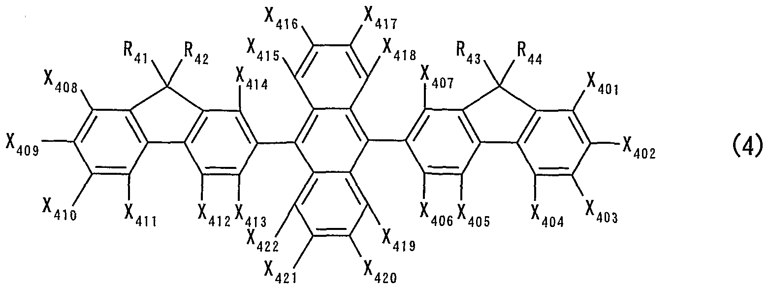
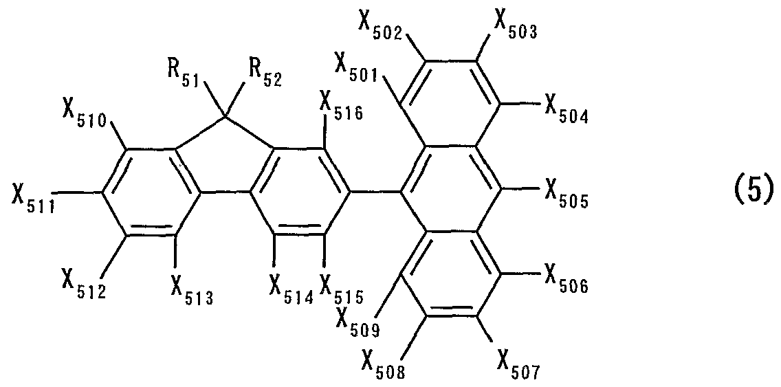
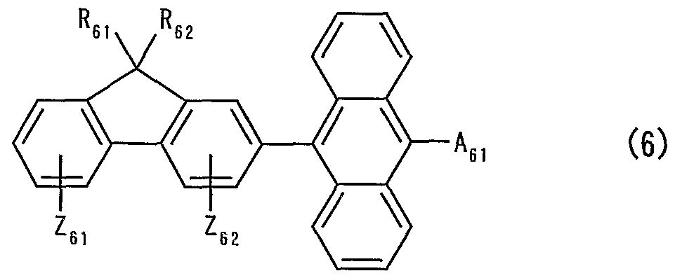


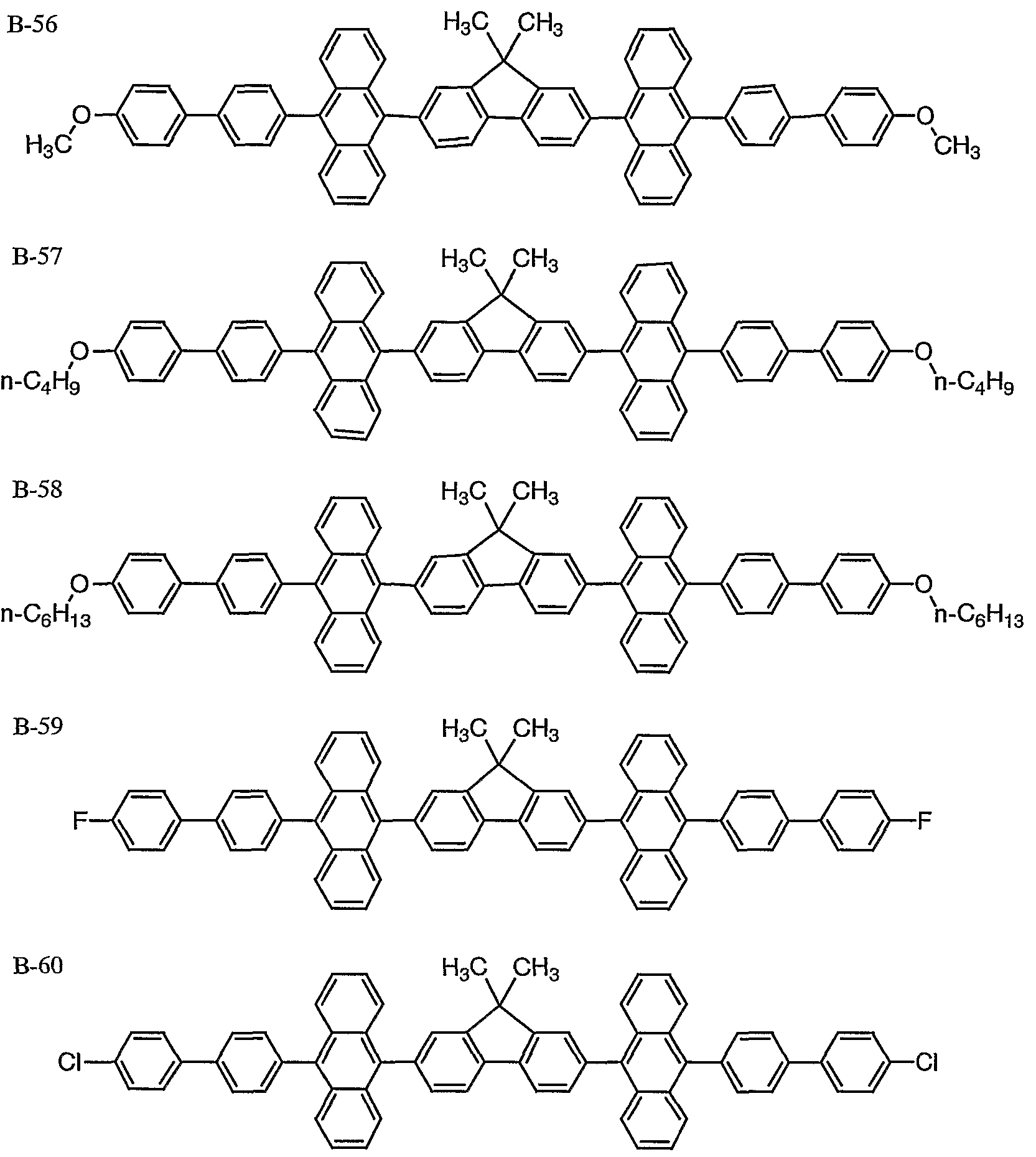


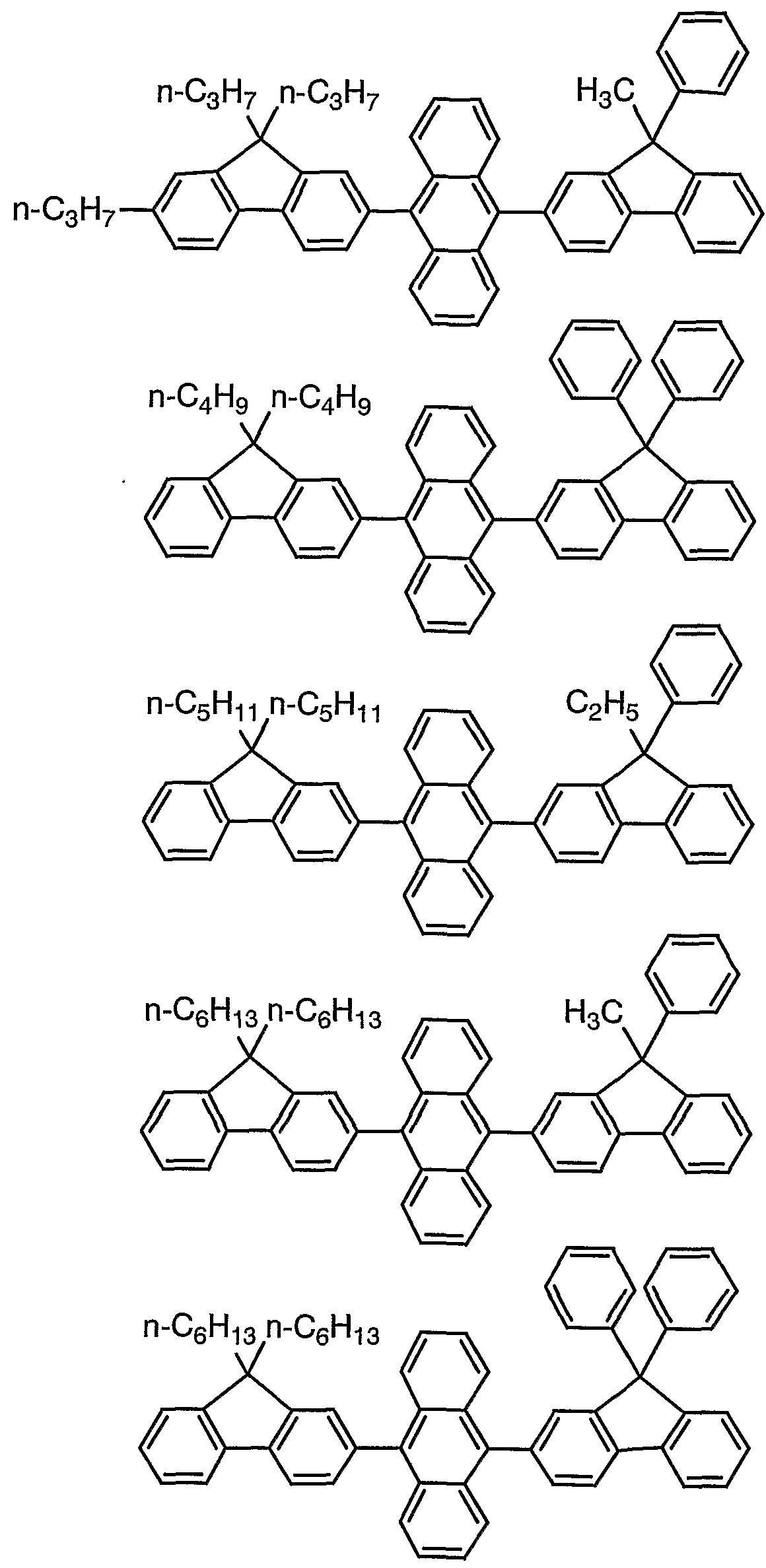


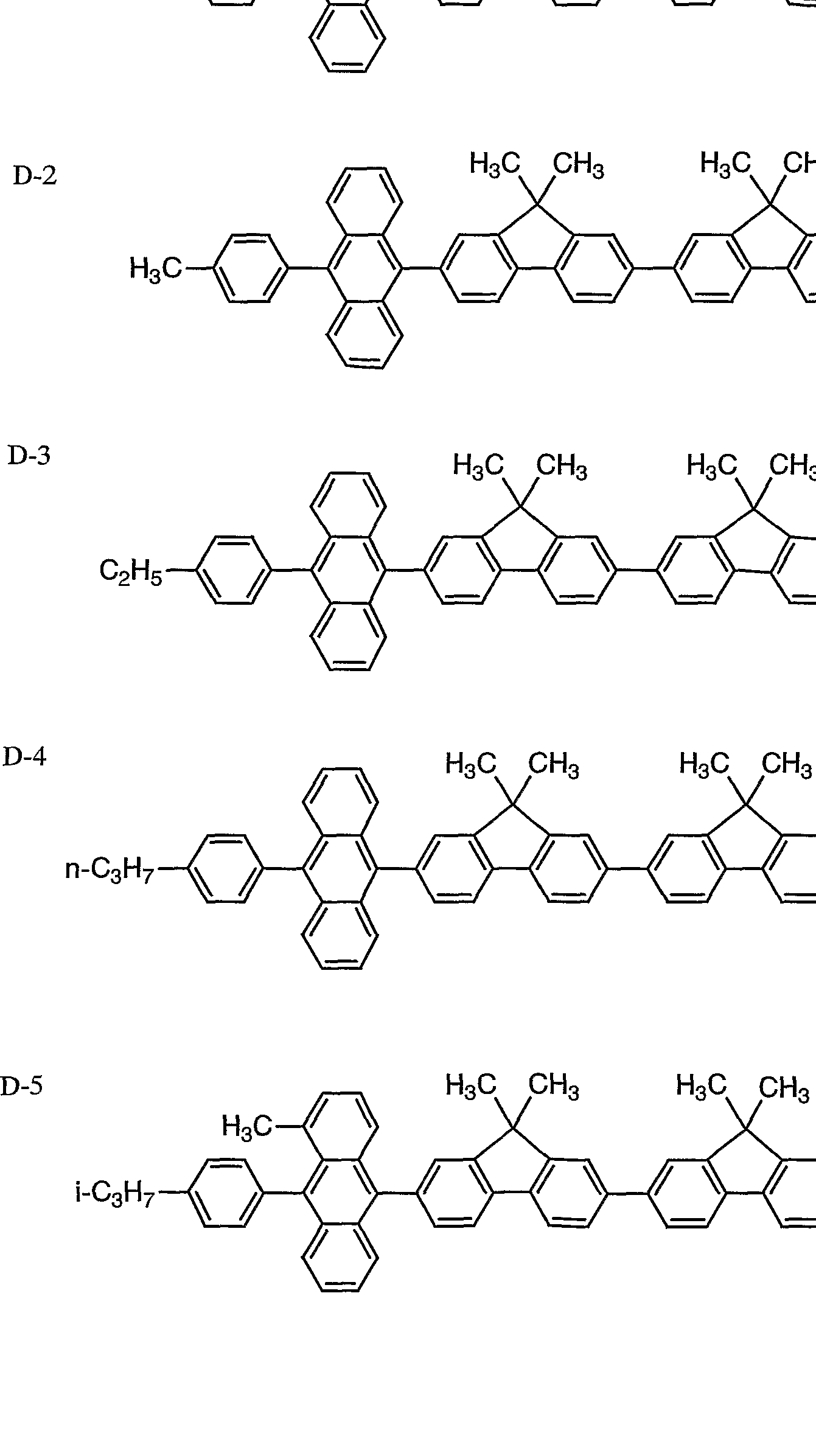


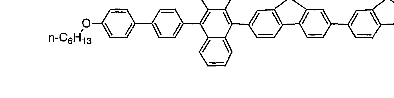


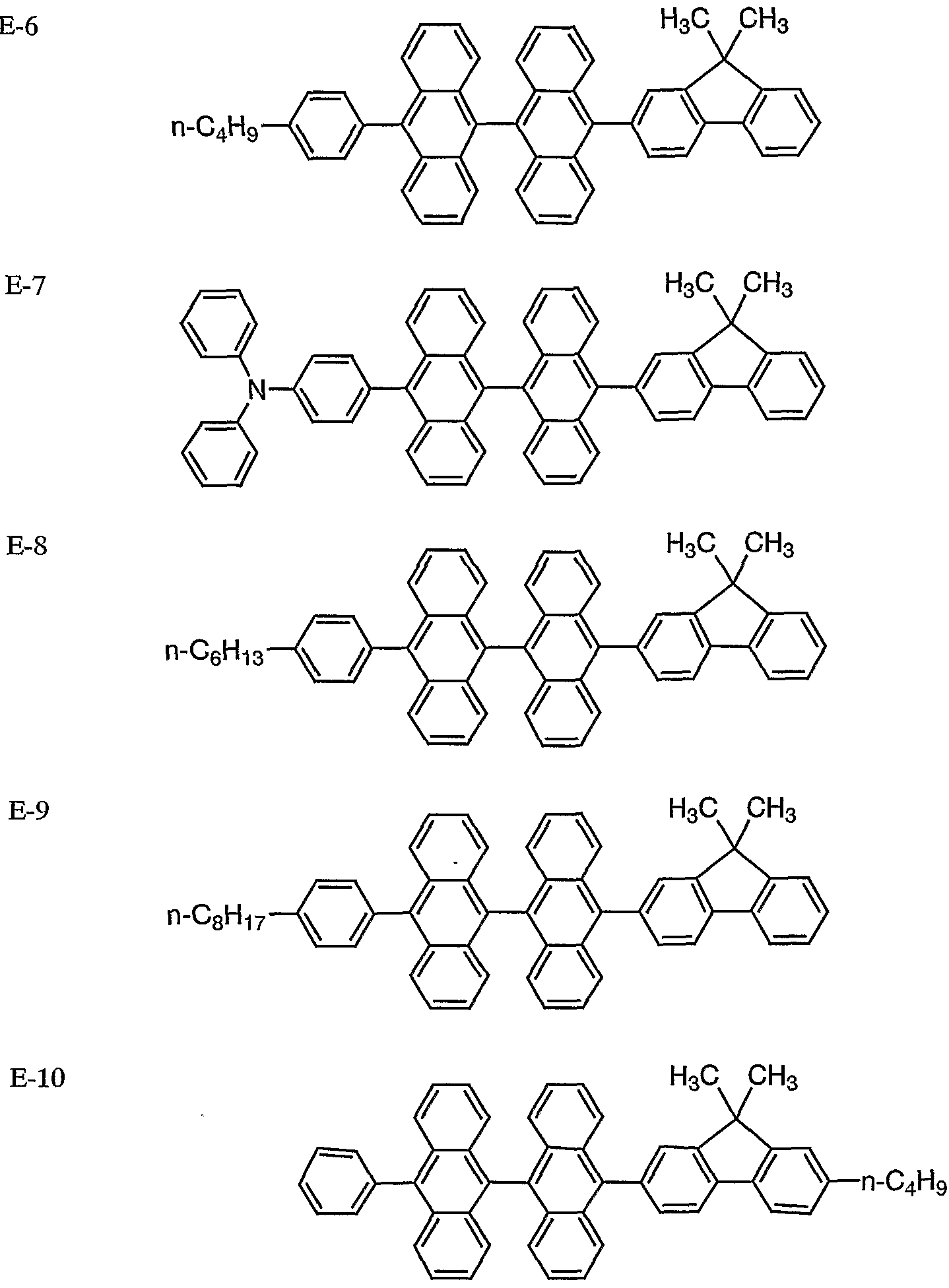


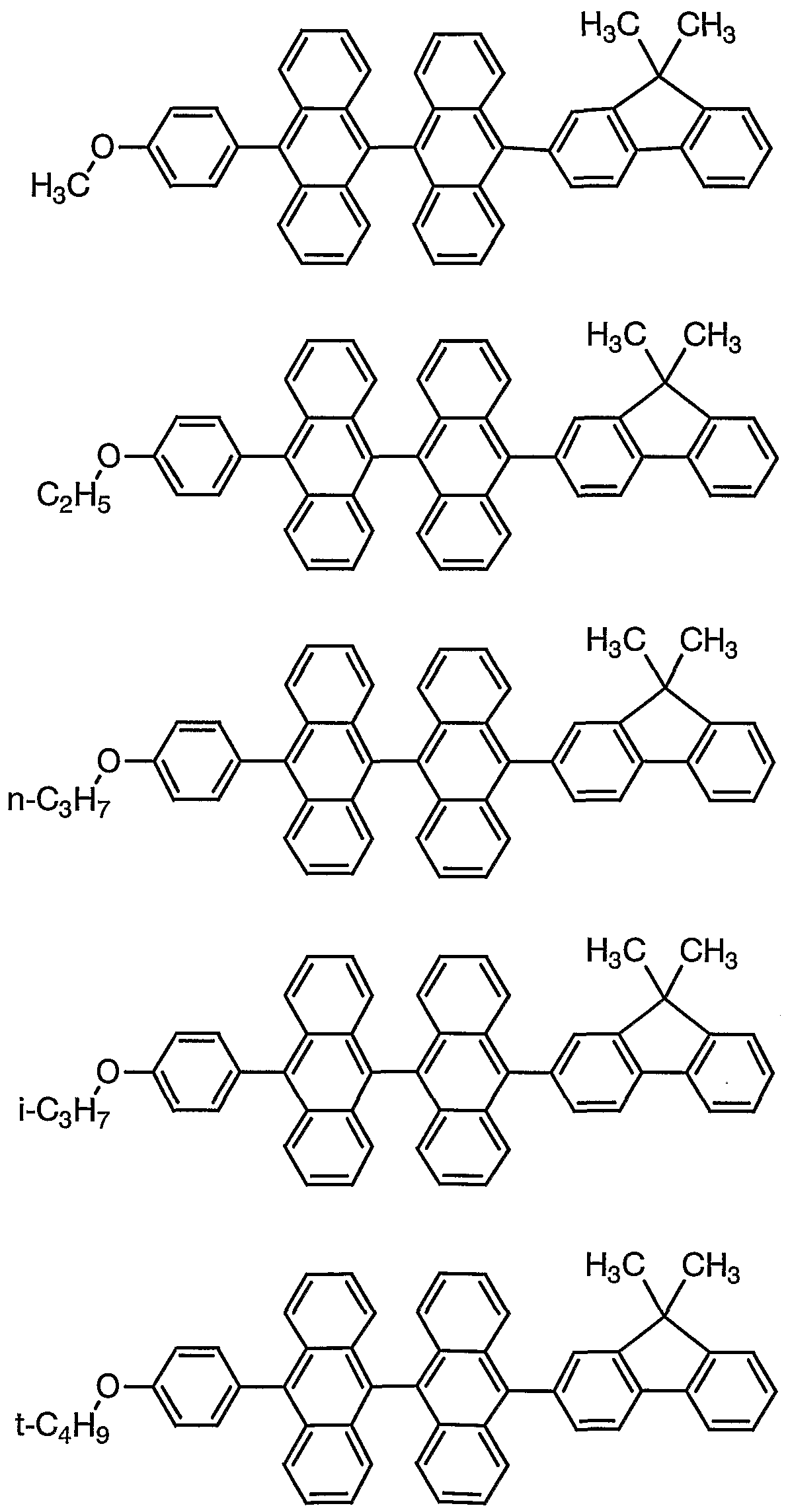


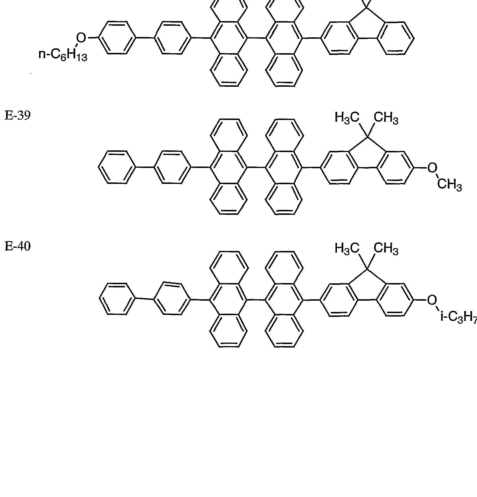


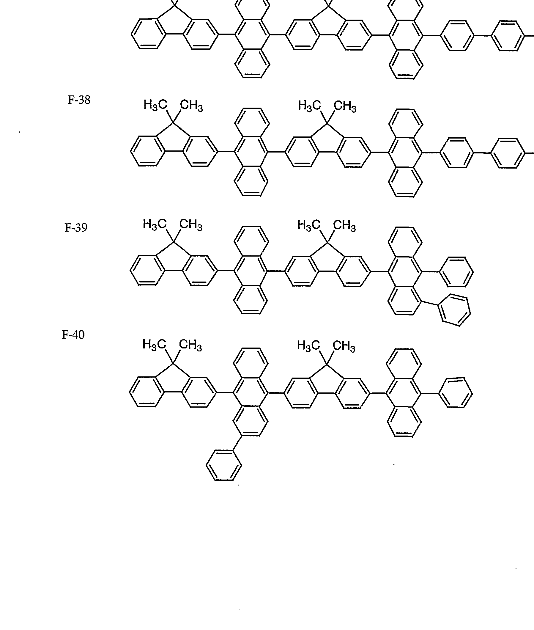


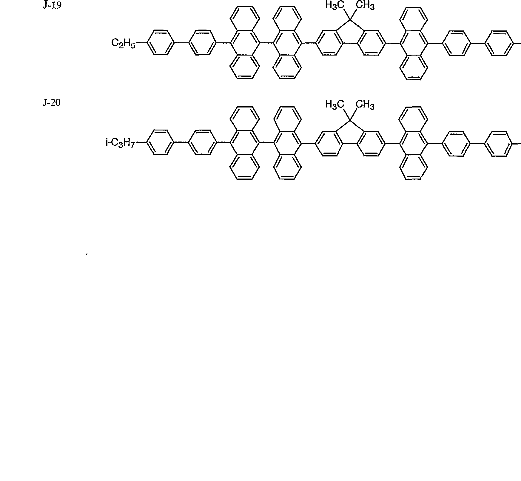


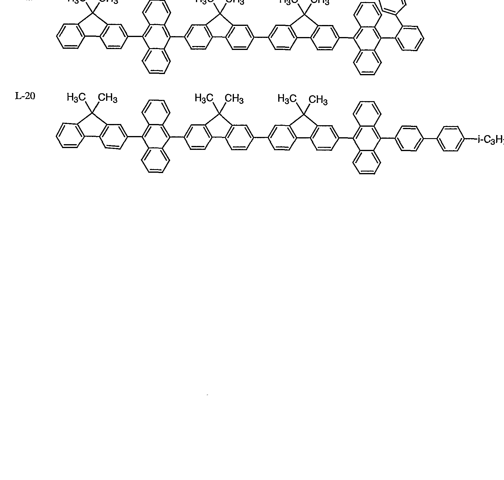


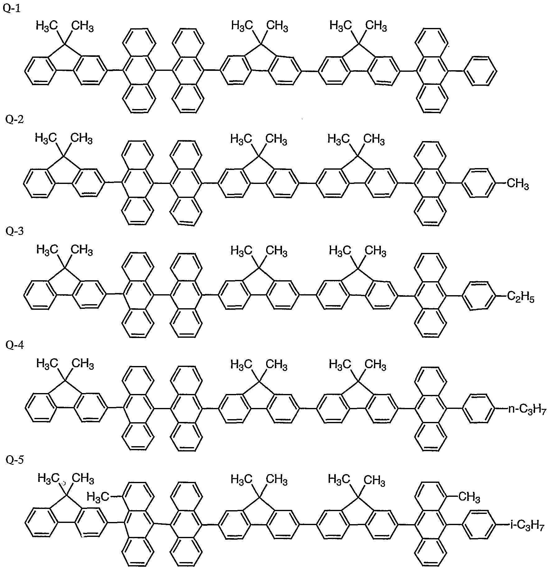


Claims


Priority Applications (3)
| Application Number | Priority Date | Filing Date | Title |
|---|---|---|---|
| US10/110,241 US6929870B2 (en) | 2000-08-10 | 2001-08-10 | Hydrocarbon compounds, materials for organic electroluminescent elements and organic electroluminescent elements |
| EP01955670A EP1221434B1 (en) | 2000-08-10 | 2001-08-10 | Hydrocarbon compound, material for organic electroluminescent element and organic electroluminescent element |
| US10/930,874 US7166240B2 (en) | 2000-08-10 | 2004-09-01 | Hydrocarbon compounds, materials for organic electroluminescent elements and organic electroluminescent elements |
Applications Claiming Priority (4)
| Application Number | Priority Date | Filing Date | Title |
|---|---|---|---|
| JP2000-242476 | 2000-08-10 | ||
| JP2000242476 | 2000-08-10 | ||
| JP2000268568 | 2000-09-05 | ||
| JP2000-268568 | 2000-09-05 |
Related Child Applications (2)
| Application Number | Title | Priority Date | Filing Date |
|---|---|---|---|
| US10110241 A-371-Of-International | 2001-08-10 | ||
| US10/930,874 Division US7166240B2 (en) | 2000-08-10 | 2004-09-01 | Hydrocarbon compounds, materials for organic electroluminescent elements and organic electroluminescent elements |
Publications (1)
| Publication Number | Publication Date |
|---|---|
| WO2002014244A1 true WO2002014244A1 (en) | 2002-02-21 |
Family
ID=26597714
Family Applications (1)
| Application Number | Title | Priority Date | Filing Date |
|---|---|---|---|
| PCT/JP2001/006920 WO2002014244A1 (en) | 2000-08-10 | 2001-08-10 | Hydrocarbon compound, material for organic electroluminescent element and organic electroluminescent element |
Country Status (5)
| Country | Link |
|---|---|
| US (2) | US6929870B2 (en) |
| EP (1) | EP1221434B1 (en) |
| KR (1) | KR100480424B1 (en) |
| TW (1) | TWI290546B (en) |
| WO (1) | WO2002014244A1 (en) |
Cited By (15)
| Publication number | Priority date | Publication date | Assignee | Title |
|---|---|---|---|---|
| WO2003087023A1 (en) * | 2002-04-17 | 2003-10-23 | Idemitsu Kosan Co., Ltd. | Novel aromatic compound and organic electroluminescnet element containing the same |
| WO2004018587A1 (en) * | 2002-08-23 | 2004-03-04 | Idemitsu Kosan Co., Ltd. | Organic electroluminescence device and anthracene derivative |
| WO2004020372A1 (en) * | 2002-08-27 | 2004-03-11 | Canon Kabushiki Kaisha | Fluorene compound and organic luminescent device using the same |
| EP1425168A4 (en) * | 2001-07-20 | 2007-01-03 | Univ Rochester | Light-emitting organic oligomer compositions |
| WO2007123339A1 (en) * | 2006-04-21 | 2007-11-01 | Lg Chem, Ltd. | Novel anthracene derivatives, method for preparation thereof, and organic electronic device using the same |
| EP1922382A1 (en) | 2005-08-16 | 2008-05-21 | Gracel Display Inc. | Green electroluminescent compounds and organic electroluminescent device using the same |
| WO2009066815A1 (en) * | 2007-11-23 | 2009-05-28 | Gracel Display Inc. | Luminescent compounds and electroluminescent device using the same |
| JP2009249378A (en) * | 2008-04-02 | 2009-10-29 | Gracel Display Inc | New organic electroluminescent compound, and organic electroluminescent element using the same |
| WO2010106806A1 (en) * | 2009-03-19 | 2010-09-23 | 三井化学株式会社 | Aromatic amine derivative and organic electroluminescent element using same |
| WO2010134352A1 (en) | 2009-05-22 | 2010-11-25 | 出光興産株式会社 | Organic electroluminescent element |
| WO2010134350A1 (en) | 2009-05-22 | 2010-11-25 | 出光興産株式会社 | Organic electroluminescent element |
| WO2010143434A1 (en) | 2009-06-12 | 2010-12-16 | 出光興産株式会社 | Organic electroluminescent element |
| WO2012070233A1 (en) | 2010-11-22 | 2012-05-31 | Idemitsu Kosan Co.,Ltd. | Organic electroluminescence device |
| EP3211682A1 (en) | 2011-11-22 | 2017-08-30 | Idemitsu Kosan Co., Ltd | Aromatic heterocyclic derivative, organic electroluminescence device material and organic electroluminescence device field |
| CN113831912A (en) * | 2021-10-20 | 2021-12-24 | 广东石油化工学院 | Oxytetracycline ratiometric fluorescent probe based on autofluorescence enhancement, and preparation and application thereof |
Families Citing this family (56)
| Publication number | Priority date | Publication date | Assignee | Title |
|---|---|---|---|---|
| SG114514A1 (en) * | 2001-11-28 | 2005-09-28 | Univ Singapore | Organic light emitting diode (oled) |
| EP2249413A3 (en) * | 2002-04-01 | 2011-02-02 | Konica Corporation | Support and organic electroluminescence element comprising the support |
| JP4025137B2 (en) * | 2002-08-02 | 2007-12-19 | 出光興産株式会社 | Anthracene derivative and organic electroluminescence device using the same |
| JP4125076B2 (en) | 2002-08-30 | 2008-07-23 | キヤノン株式会社 | Monoaminofluorene compound and organic light-emitting device using the same |
| US20040131881A1 (en) * | 2002-12-31 | 2004-07-08 | Eastman Kodak Company | Complex fluorene-containing compounds for use in OLED devices |
| US7867629B2 (en) | 2003-01-10 | 2011-01-11 | Idemitsu Kosan Co., Ltd. | Nitrogenous heterocyclic derivative and organic electroluminescent element employing the same |
| US7651787B2 (en) * | 2003-02-19 | 2010-01-26 | Lg Display Co., Ltd. | Organic electroluminescent device |
| JP3840235B2 (en) * | 2003-06-27 | 2006-11-01 | キヤノン株式会社 | Organic light emitting device |
| JP4035482B2 (en) * | 2003-06-27 | 2008-01-23 | キヤノン株式会社 | Substituted anthryl derivative and organic light emitting device using the same |
| US7887931B2 (en) * | 2003-10-24 | 2011-02-15 | Global Oled Technology Llc | Electroluminescent device with anthracene derivative host |
| US7056601B2 (en) * | 2003-10-24 | 2006-06-06 | Eastman Kodak Company | OLED device with asymmetric host |
| EP2910619B1 (en) | 2003-12-19 | 2016-07-20 | Idemitsu Kosan Co., Ltd | Light-emitting material for organic electroluminescent device, organic electroluminescent device using same, and material for organic electroluminescent device |
| US20050276947A1 (en) * | 2004-06-15 | 2005-12-15 | Ping-Tsung Huang | Package structure of organic electroluminescent device and package method thereof |
| JPWO2005123634A1 (en) * | 2004-06-16 | 2008-04-10 | 出光興産株式会社 | Fluorene derivative and organic electroluminescence device using the same |
| US20100025661A1 (en) * | 2004-07-02 | 2010-02-04 | Guofang Wang | Luminescent material and organic electroluminescent device using the same |
| JP4616596B2 (en) * | 2004-08-27 | 2011-01-19 | 株式会社 日立ディスプレイズ | Manufacturing method of electronic device |
| US7351999B2 (en) * | 2004-12-16 | 2008-04-01 | Au Optronics Corporation | Organic light-emitting device with improved layer structure |
| US8334058B2 (en) * | 2005-04-14 | 2012-12-18 | Merck Patent Gmbh | Compounds for organic electronic devices |
| US7479330B2 (en) * | 2005-05-26 | 2009-01-20 | Au Optronics Corporation | Anthracene derivatives for organic electroluminescent device |
| US7705346B2 (en) * | 2005-06-06 | 2010-04-27 | Xerox Corporation | Barrier layer for an organic electronic device |
| JP4305425B2 (en) * | 2005-07-20 | 2009-07-29 | セイコーエプソン株式会社 | Electronic devices and electronic equipment |
| TWI306113B (en) * | 2005-08-03 | 2009-02-11 | Chi Mei Optoelectronics Corp | Organic light emitting diode |
| US20090261711A1 (en) * | 2005-09-15 | 2009-10-22 | Idemitsu Kosan Co., Ltd. | Asymmetric fluorene derivative and organic electroluminescent element containing the same |
| US7901793B2 (en) * | 2005-09-23 | 2011-03-08 | Samsung Mobile Display Co., Ltd. | Organic light-emitting compound and organic light-emitting device containing the same |
| DE102005058557A1 (en) * | 2005-12-08 | 2007-06-14 | Merck Patent Gmbh | Organic electroluminescent device |
| JP2007332127A (en) * | 2005-12-20 | 2007-12-27 | Canon Inc | Compound and organic light-emitting element |
| JP4819655B2 (en) * | 2006-04-27 | 2011-11-24 | キヤノン株式会社 | 4-Arylfluorene compound and organic light-emitting device using the same |
| KR101320382B1 (en) * | 2006-05-22 | 2013-10-29 | 삼성디스플레이 주식회사 | Organic light emitting compound and organic light emitting device comprising the same |
| KR100820250B1 (en) * | 2006-08-21 | 2008-04-11 | (주)그라쎌 | Luminescent compounds and electroluminescent device using the same |
| WO2008056652A1 (en) * | 2006-11-09 | 2008-05-15 | Idemitsu Kosan Co., Ltd. | Organic el material-containing solution, method for synthesizing organic el material, compound synthesized by the synthesizing method, method for forming thin film of organic el material, thin film of organic el material, and organic el device |
| KR100857024B1 (en) * | 2007-04-13 | 2008-09-05 | (주)그라쎌 | Electroluminescent compounds with high efficiency and organic light-emitting diode using the same |
| JP5208591B2 (en) | 2007-06-28 | 2013-06-12 | 株式会社半導体エネルギー研究所 | Light emitting device and lighting device |
| KR100901887B1 (en) | 2008-03-14 | 2009-06-09 | (주)그라쎌 | Novel organic electroluminescent compounds and organic electroluminescent device using the same |
| KR100946411B1 (en) | 2008-03-28 | 2010-03-09 | 다우어드밴스드디스플레이머티리얼 유한회사 | Novel organic electroluminescent compounds and organic electroluminescent device using the same |
| KR101495547B1 (en) | 2008-04-17 | 2015-02-25 | 롬엔드하스전자재료코리아유한회사 | Novel compounds for electronic material and organic electronic device using the same |
| KR20090111915A (en) | 2008-04-23 | 2009-10-28 | (주)그라쎌 | Novel organic electroluminescent compounds and organic electroluminescent device using the same |
| KR20100000121A (en) | 2008-06-24 | 2010-01-06 | 다우어드밴스드디스플레이머티리얼 유한회사 | Novel organic electroluminescent compounds and organic electroluminescent device using the same |
| KR20100109293A (en) * | 2009-03-31 | 2010-10-08 | 다우어드밴스드디스플레이머티리얼 유한회사 | Novel organic electroluminescent compounds and organic electroluminescent device using the same |
| KR101427605B1 (en) * | 2009-03-31 | 2014-08-07 | 롬엔드하스전자재료코리아유한회사 | Novel organic electroluminescent compounds and organic electroluminescent device using the same |
| KR20100137198A (en) * | 2009-06-22 | 2010-12-30 | 다우어드밴스드디스플레이머티리얼 유한회사 | Novel organic electroluminescent compounds and organic electroluminescent device using the same |
| TWI402243B (en) * | 2010-01-06 | 2013-07-21 | Univ Nat Chiao Tung | Organic light emitting matterial |
| TWI421230B (en) * | 2010-01-06 | 2014-01-01 | Univ Nat Chiao Tung | Organic light emitting element and method of forming the same |
| KR101681214B1 (en) * | 2010-01-08 | 2016-12-01 | 에스에프씨 주식회사 | Host compounds and organic electroluminescent devices using the same |
| JPWO2012017680A1 (en) * | 2010-08-05 | 2013-10-03 | 出光興産株式会社 | Organic electroluminescence device |
| CN101973933B (en) * | 2010-10-22 | 2012-05-02 | 湘潭大学 | Bi(phenylpyridine) fluorene derivatives and binuclear cyclometalated platinum complex liquid crystal polarized luminescent materials |
| TW201229204A (en) * | 2010-12-17 | 2012-07-16 | Du Pont | Anthracene derivative compounds for electronic applications |
| JP5946963B2 (en) | 2012-07-19 | 2016-07-06 | エルジー・ケム・リミテッド | Polycyclic compound and organic electronic device containing the same |
| KR102038969B1 (en) * | 2013-04-12 | 2019-11-01 | 삼성디스플레이 주식회사 | Organic compound and organic light emitting diode device including the same |
| CN105294647A (en) * | 2015-05-22 | 2016-02-03 | 南京高光半导体材料有限公司 | Organic electroluminescent material and electroluminescent device |
| CN104892432B (en) * | 2015-05-29 | 2017-07-21 | 上海道亦化工科技有限公司 | A kind of anthracene class organic electroluminescent compounds and its organic electroluminescence device |
| CN106431805B (en) * | 2016-09-09 | 2019-05-21 | 陕西金士盾警用装备有限公司 | Organic fluorescence small molecule thin-film material and its application in the detection of DNT and TNT steam |
| CN106565434B (en) * | 2016-10-28 | 2020-02-14 | 吉林奥来德光电材料股份有限公司 | Anthracene compound, preparation method thereof and organic light-emitting device |
| US11581487B2 (en) | 2017-04-26 | 2023-02-14 | Oti Lumionics Inc. | Patterned conductive coating for surface of an opto-electronic device |
| US11751415B2 (en) | 2018-02-02 | 2023-09-05 | Oti Lumionics Inc. | Materials for forming a nucleation-inhibiting coating and devices incorporating same |
| KR102583620B1 (en) * | 2018-11-23 | 2023-09-26 | 엘지디스플레이 주식회사 | Light emitting diode and light emitting device having the diode |
| CN113785411B (en) | 2019-03-07 | 2023-04-11 | Oti照明公司 | Material for forming nucleation inhibiting coatings and apparatus incorporating the same |
Citations (5)
| Publication number | Priority date | Publication date | Assignee | Title |
|---|---|---|---|---|
| JPH0812600A (en) | 1994-04-26 | 1996-01-16 | Tdk Corp | Phenylanthracene derivative and organic el element |
| JPH1036832A (en) | 1996-07-30 | 1998-02-10 | Mitsubishi Chem Corp | Organic electroluminescence element |
| JPH10294179A (en) | 1997-04-21 | 1998-11-04 | Mitsubishi Chem Corp | Organic electroluminescence element and luminescence material |
| JPH11111460A (en) | 1997-10-06 | 1999-04-23 | Toyo Ink Mfg Co Ltd | Organic electroluminescent element material and organic electroluminescent element using the same |
| JPH11111458A (en) | 1997-09-29 | 1999-04-23 | Toyo Ink Mfg Co Ltd | Organic electroluminescent element material and organic electroluminescent element using the same |
Family Cites Families (4)
| Publication number | Priority date | Publication date | Assignee | Title |
|---|---|---|---|---|
| US5378519A (en) * | 1992-04-28 | 1995-01-03 | Canon Kabushiki Kaisha | Electroluminescent device |
| US6355756B1 (en) * | 1999-05-18 | 2002-03-12 | International Business Machines Corporation | Dual purpose electroactive copolymers, preparation thereof, and use in opto-electronic devices |
| KR100809132B1 (en) * | 1999-09-21 | 2008-02-29 | 이데미쓰 고산 가부시키가이샤 | Organic electroluminescence and organic luminous medium |
| US6479172B2 (en) * | 2001-01-26 | 2002-11-12 | Xerox Corporation | Electroluminescent (EL) devices |
-
2001
- 2001-08-10 WO PCT/JP2001/006920 patent/WO2002014244A1/en active IP Right Grant
- 2001-08-10 EP EP01955670A patent/EP1221434B1/en not_active Expired - Lifetime
- 2001-08-10 TW TW090119621A patent/TWI290546B/en not_active IP Right Cessation
- 2001-08-10 KR KR10-2002-7004571A patent/KR100480424B1/en active IP Right Grant
- 2001-08-10 US US10/110,241 patent/US6929870B2/en not_active Expired - Lifetime
-
2004
- 2004-09-01 US US10/930,874 patent/US7166240B2/en not_active Expired - Lifetime
Patent Citations (5)
| Publication number | Priority date | Publication date | Assignee | Title |
|---|---|---|---|---|
| JPH0812600A (en) | 1994-04-26 | 1996-01-16 | Tdk Corp | Phenylanthracene derivative and organic el element |
| JPH1036832A (en) | 1996-07-30 | 1998-02-10 | Mitsubishi Chem Corp | Organic electroluminescence element |
| JPH10294179A (en) | 1997-04-21 | 1998-11-04 | Mitsubishi Chem Corp | Organic electroluminescence element and luminescence material |
| JPH11111458A (en) | 1997-09-29 | 1999-04-23 | Toyo Ink Mfg Co Ltd | Organic electroluminescent element material and organic electroluminescent element using the same |
| JPH11111460A (en) | 1997-10-06 | 1999-04-23 | Toyo Ink Mfg Co Ltd | Organic electroluminescent element material and organic electroluminescent element using the same |
Non-Patent Citations (4)
| Title |
|---|
| J. APPL. PHYS., vol. 65, 1989, pages 3610 |
| PROCEEDINGS OF SPIE - ORGANIC LIGHT-EMITTING MATERIALS AND DEVICES IV, vol. 4105, February 2001 (2001-02-01), pages 69 - 74 |
| See also references of EP1221434A4 |
| WEBER EDWIN ET AL.: "Versatile and convenient lattice hosts derived from singly bridged triarylmethane frameworks. X-ray crystal structures of three inclusion compounds", J. CHEM. SOC., PERKIN TRANS. 2, vol. 12, 1990, pages 2167 - 2177, XP002906731 * |
Cited By (23)
| Publication number | Priority date | Publication date | Assignee | Title |
|---|---|---|---|---|
| EP1425168A4 (en) * | 2001-07-20 | 2007-01-03 | Univ Rochester | Light-emitting organic oligomer compositions |
| EP1496041A4 (en) * | 2002-04-17 | 2005-11-02 | Idemitsu Kosan Co | Novel aromatic compound and organic electroluminescnet element containing the same |
| WO2003087023A1 (en) * | 2002-04-17 | 2003-10-23 | Idemitsu Kosan Co., Ltd. | Novel aromatic compound and organic electroluminescnet element containing the same |
| WO2004018587A1 (en) * | 2002-08-23 | 2004-03-04 | Idemitsu Kosan Co., Ltd. | Organic electroluminescence device and anthracene derivative |
| WO2004020372A1 (en) * | 2002-08-27 | 2004-03-11 | Canon Kabushiki Kaisha | Fluorene compound and organic luminescent device using the same |
| US7241513B2 (en) | 2002-08-27 | 2007-07-10 | Canon Kabushiki Kaisha | Fluorene compound and organic luminescent device using the same |
| KR100761621B1 (en) * | 2002-08-27 | 2007-10-04 | 캐논 가부시끼가이샤 | Fluorene compound and organic luminescent device using the same |
| EP1922382A1 (en) | 2005-08-16 | 2008-05-21 | Gracel Display Inc. | Green electroluminescent compounds and organic electroluminescent device using the same |
| JP2009534376A (en) * | 2006-04-21 | 2009-09-24 | エルジー・ケム・リミテッド | NOVEL ANTHRACENE DERIVATIVE, PROCESS FOR PRODUCING THE SAME, AND ORGANIC ELECTRONIC DEVICE USING THE SAME |
| WO2007123339A1 (en) * | 2006-04-21 | 2007-11-01 | Lg Chem, Ltd. | Novel anthracene derivatives, method for preparation thereof, and organic electronic device using the same |
| US8173273B2 (en) | 2006-04-21 | 2012-05-08 | Lg Chem, Ltd. | Anthracene derivatives, method for preparation thereof, and organic electronic device using the same |
| WO2009066815A1 (en) * | 2007-11-23 | 2009-05-28 | Gracel Display Inc. | Luminescent compounds and electroluminescent device using the same |
| JP2009249378A (en) * | 2008-04-02 | 2009-10-29 | Gracel Display Inc | New organic electroluminescent compound, and organic electroluminescent element using the same |
| US8980442B2 (en) | 2009-03-19 | 2015-03-17 | Mitsui Chemicals, Inc. | Aromatic amine derivative and organic electroluminescent element using same |
| WO2010106806A1 (en) * | 2009-03-19 | 2010-09-23 | 三井化学株式会社 | Aromatic amine derivative and organic electroluminescent element using same |
| WO2010134352A1 (en) | 2009-05-22 | 2010-11-25 | 出光興産株式会社 | Organic electroluminescent element |
| WO2010134350A1 (en) | 2009-05-22 | 2010-11-25 | 出光興産株式会社 | Organic electroluminescent element |
| WO2010143434A1 (en) | 2009-06-12 | 2010-12-16 | 出光興産株式会社 | Organic electroluminescent element |
| EP3104428A1 (en) | 2009-06-12 | 2016-12-14 | Idemitsu Kosan Co., Ltd | Organic electroluminescence device |
| WO2012070234A1 (en) | 2010-11-22 | 2012-05-31 | Idemitsu Kosan Co.,Ltd. | Organic electroluminescence device |
| WO2012070233A1 (en) | 2010-11-22 | 2012-05-31 | Idemitsu Kosan Co.,Ltd. | Organic electroluminescence device |
| EP3211682A1 (en) | 2011-11-22 | 2017-08-30 | Idemitsu Kosan Co., Ltd | Aromatic heterocyclic derivative, organic electroluminescence device material and organic electroluminescence device field |
| CN113831912A (en) * | 2021-10-20 | 2021-12-24 | 广东石油化工学院 | Oxytetracycline ratiometric fluorescent probe based on autofluorescence enhancement, and preparation and application thereof |
Also Published As
| Publication number | Publication date |
|---|---|
| US20050074631A1 (en) | 2005-04-07 |
| EP1221434A4 (en) | 2004-12-08 |
| US7166240B2 (en) | 2007-01-23 |
| EP1221434A1 (en) | 2002-07-10 |
| TWI290546B (en) | 2007-12-01 |
| US6929870B2 (en) | 2005-08-16 |
| EP1221434B1 (en) | 2012-06-27 |
| US20030087126A1 (en) | 2003-05-08 |
| KR100480424B1 (en) | 2005-04-07 |
| KR20020062922A (en) | 2002-07-31 |
Similar Documents
| Publication | Publication Date | Title |
|---|---|---|
| WO2002014244A1 (en) | Hydrocarbon compound, material for organic electroluminescent element and organic electroluminescent element | |
| JP4338367B2 (en) | Compound, organic electroluminescent element material, and organic electroluminescent element | |
| JP4996794B2 (en) | Hydrocarbon compound, material for organic electroluminescence device, and organic electroluminescence device | |
| JP4220696B2 (en) | Hydrocarbon compound, material for organic electroluminescence device, and organic electroluminescence device | |
| JP4080213B2 (en) | Organic electroluminescence device | |
| CN1978586A (en) | Material for organic electroluminescent device and organic electroluminescent device using the same | |
| JP2003261472A (en) | Organic electroluminescent element and new hydrocarbon compound | |
| JP3998337B2 (en) | Hydrocarbon compounds and organic electroluminescent devices | |
| JP2001257074A (en) | Hydrocarbon compound and organic electroluminescence element | |
| JP3792100B2 (en) | Hydrocarbon compounds and organic electroluminescent devices | |
| JP2003282268A (en) | Organic electroluminescent device and new thiophene compound | |
| JP2003073343A (en) | Amine compound and organic electroluminescent element having the compound | |
| JP2001267078A (en) | Hydrocarbon compound and organic electroluminescence element | |
| JP4263872B2 (en) | Amine compound and organic electroluminescent device containing the compound | |
| JP3794847B2 (en) | Hydrocarbon compounds and organic electroluminescent devices | |
| JP2001267075A (en) | Hydrocarbon compound and organic electroluminescence element | |
| JP2001244075A (en) | Hydrocarbon compound and organic electroluminescent element | |
| JP2003081923A (en) | Amine compound and organic electroluminescent element containing the same | |
| JP2000086549A (en) | Hydrocarbon compound and organic electroluminescent element | |
| JP4527902B2 (en) | Hydrocarbon compounds and organic electroluminescent devices | |
| JP2003272863A (en) | Organic electroluminescent element | |
| JP2003151778A (en) | Organic electroluminescent element | |
| JP2002313575A (en) | Hydrocarbon compound and organic electroluminescent element | |
| JP4578175B2 (en) | Material for organic electroluminescence device comprising methine compound, organic electroluminescence device using the same, and novel methine compound | |
| JP2003081969A (en) | Organic electroluminescent element and novel thiophene |
Legal Events
| Date | Code | Title | Description |
|---|---|---|---|
| AK | Designated states |
Kind code of ref document: A1 Designated state(s): KR US |
|
| AL | Designated countries for regional patents |
Kind code of ref document: A1 Designated state(s): DE FR NL |
|
| WWE | Wipo information: entry into national phase |
Ref document number: 2001955670 Country of ref document: EP |
|
| WWE | Wipo information: entry into national phase |
Ref document number: 10110241 Country of ref document: US Ref document number: 1020027004571 Country of ref document: KR |
|
| 121 | Ep: the epo has been informed by wipo that ep was designated in this application | ||
| WWP | Wipo information: published in national office |
Ref document number: 2001955670 Country of ref document: EP |
|
| WWP | Wipo information: published in national office |
Ref document number: 1020027004571 Country of ref document: KR |
|
| WWG | Wipo information: grant in national office |
Ref document number: 1020027004571 Country of ref document: KR |