JP4819655B2 - 4-Arylfluorene compound and organic light-emitting device using the same - Google Patents
4-Arylfluorene compound and organic light-emitting device using the same Download PDFInfo
- Publication number
- JP4819655B2 JP4819655B2 JP2006310380A JP2006310380A JP4819655B2 JP 4819655 B2 JP4819655 B2 JP 4819655B2 JP 2006310380 A JP2006310380 A JP 2006310380A JP 2006310380 A JP2006310380 A JP 2006310380A JP 4819655 B2 JP4819655 B2 JP 4819655B2
- Authority
- JP
- Japan
- Prior art keywords
- group
- compound
- organic light
- light emitting
- emitting device
- Prior art date
- Legal status (The legal status is an assumption and is not a legal conclusion. Google has not performed a legal analysis and makes no representation as to the accuracy of the status listed.)
- Expired - Fee Related
Links
- 0 CC(C)(c1cc(*)ccc1-1)c2c-1c(-c(cc1)c3c4c1-c1c(-c5ccccc5)c(cccc5)c5c(-c5ccccc5)c1-c4ccc3)cc(*)c2 Chemical compound CC(C)(c1cc(*)ccc1-1)c2c-1c(-c(cc1)c3c4c1-c1c(-c5ccccc5)c(cccc5)c5c(-c5ccccc5)c1-c4ccc3)cc(*)c2 0.000 description 1
Images


Classifications
-
- C—CHEMISTRY; METALLURGY
- C09—DYES; PAINTS; POLISHES; NATURAL RESINS; ADHESIVES; COMPOSITIONS NOT OTHERWISE PROVIDED FOR; APPLICATIONS OF MATERIALS NOT OTHERWISE PROVIDED FOR
- C09K—MATERIALS FOR MISCELLANEOUS APPLICATIONS, NOT PROVIDED FOR ELSEWHERE
- C09K11/00—Luminescent, e.g. electroluminescent, chemiluminescent materials
- C09K11/06—Luminescent, e.g. electroluminescent, chemiluminescent materials containing organic luminescent materials
-
- C—CHEMISTRY; METALLURGY
- C07—ORGANIC CHEMISTRY
- C07C—ACYCLIC OR CARBOCYCLIC COMPOUNDS
- C07C13/00—Cyclic hydrocarbons containing rings other than, or in addition to, six-membered aromatic rings
- C07C13/28—Polycyclic hydrocarbons or acyclic hydrocarbon derivatives thereof
- C07C13/32—Polycyclic hydrocarbons or acyclic hydrocarbon derivatives thereof with condensed rings
- C07C13/62—Polycyclic hydrocarbons or acyclic hydrocarbon derivatives thereof with condensed rings with more than three condensed rings
- C07C13/66—Polycyclic hydrocarbons or acyclic hydrocarbon derivatives thereof with condensed rings with more than three condensed rings the condensed ring system contains only four rings
-
- C—CHEMISTRY; METALLURGY
- C07—ORGANIC CHEMISTRY
- C07C—ACYCLIC OR CARBOCYCLIC COMPOUNDS
- C07C43/00—Ethers; Compounds having groups, groups or groups
- C07C43/02—Ethers
- C07C43/20—Ethers having an ether-oxygen atom bound to a carbon atom of a six-membered aromatic ring
- C07C43/21—Ethers having an ether-oxygen atom bound to a carbon atom of a six-membered aromatic ring containing rings other than six-membered aromatic rings
-
- H—ELECTRICITY
- H05—ELECTRIC TECHNIQUES NOT OTHERWISE PROVIDED FOR
- H05B—ELECTRIC HEATING; ELECTRIC LIGHT SOURCES NOT OTHERWISE PROVIDED FOR; CIRCUIT ARRANGEMENTS FOR ELECTRIC LIGHT SOURCES, IN GENERAL
- H05B33/00—Electroluminescent light sources
- H05B33/12—Light sources with substantially two-dimensional radiating surfaces
- H05B33/14—Light sources with substantially two-dimensional radiating surfaces characterised by the chemical or physical composition or the arrangement of the electroluminescent material, or by the simultaneous addition of the electroluminescent material in or onto the light source
-
- H—ELECTRICITY
- H10—SEMICONDUCTOR DEVICES; ELECTRIC SOLID-STATE DEVICES NOT OTHERWISE PROVIDED FOR
- H10K—ORGANIC ELECTRIC SOLID-STATE DEVICES
- H10K50/00—Organic light-emitting devices
- H10K50/10—OLEDs or polymer light-emitting diodes [PLED]
- H10K50/11—OLEDs or polymer light-emitting diodes [PLED] characterised by the electroluminescent [EL] layers
-
- H—ELECTRICITY
- H10—SEMICONDUCTOR DEVICES; ELECTRIC SOLID-STATE DEVICES NOT OTHERWISE PROVIDED FOR
- H10K—ORGANIC ELECTRIC SOLID-STATE DEVICES
- H10K85/00—Organic materials used in the body or electrodes of devices covered by this subclass
- H10K85/60—Organic compounds having low molecular weight
- H10K85/615—Polycyclic condensed aromatic hydrocarbons, e.g. anthracene
- H10K85/623—Polycyclic condensed aromatic hydrocarbons, e.g. anthracene containing five rings, e.g. pentacene
-
- H—ELECTRICITY
- H10—SEMICONDUCTOR DEVICES; ELECTRIC SOLID-STATE DEVICES NOT OTHERWISE PROVIDED FOR
- H10K—ORGANIC ELECTRIC SOLID-STATE DEVICES
- H10K85/00—Organic materials used in the body or electrodes of devices covered by this subclass
- H10K85/60—Organic compounds having low molecular weight
- H10K85/615—Polycyclic condensed aromatic hydrocarbons, e.g. anthracene
- H10K85/626—Polycyclic condensed aromatic hydrocarbons, e.g. anthracene containing more than one polycyclic condensed aromatic rings, e.g. bis-anthracene
-
- H—ELECTRICITY
- H10—SEMICONDUCTOR DEVICES; ELECTRIC SOLID-STATE DEVICES NOT OTHERWISE PROVIDED FOR
- H10K—ORGANIC ELECTRIC SOLID-STATE DEVICES
- H10K85/00—Organic materials used in the body or electrodes of devices covered by this subclass
- H10K85/60—Organic compounds having low molecular weight
- H10K85/631—Amine compounds having at least two aryl rest on at least one amine-nitrogen atom, e.g. triphenylamine
- H10K85/633—Amine compounds having at least two aryl rest on at least one amine-nitrogen atom, e.g. triphenylamine comprising polycyclic condensed aromatic hydrocarbons as substituents on the nitrogen atom
-
- C—CHEMISTRY; METALLURGY
- C07—ORGANIC CHEMISTRY
- C07C—ACYCLIC OR CARBOCYCLIC COMPOUNDS
- C07C2603/00—Systems containing at least three condensed rings
- C07C2603/02—Ortho- or ortho- and peri-condensed systems
- C07C2603/04—Ortho- or ortho- and peri-condensed systems containing three rings
- C07C2603/06—Ortho- or ortho- and peri-condensed systems containing three rings containing at least one ring with less than six ring members
- C07C2603/10—Ortho- or ortho- and peri-condensed systems containing three rings containing at least one ring with less than six ring members containing five-membered rings
- C07C2603/12—Ortho- or ortho- and peri-condensed systems containing three rings containing at least one ring with less than six ring members containing five-membered rings only one five-membered ring
- C07C2603/18—Fluorenes; Hydrogenated fluorenes
-
- C—CHEMISTRY; METALLURGY
- C07—ORGANIC CHEMISTRY
- C07C—ACYCLIC OR CARBOCYCLIC COMPOUNDS
- C07C2603/00—Systems containing at least three condensed rings
- C07C2603/02—Ortho- or ortho- and peri-condensed systems
- C07C2603/04—Ortho- or ortho- and peri-condensed systems containing three rings
- C07C2603/22—Ortho- or ortho- and peri-condensed systems containing three rings containing only six-membered rings
- C07C2603/24—Anthracenes; Hydrogenated anthracenes
-
- C—CHEMISTRY; METALLURGY
- C07—ORGANIC CHEMISTRY
- C07C—ACYCLIC OR CARBOCYCLIC COMPOUNDS
- C07C2603/00—Systems containing at least three condensed rings
- C07C2603/02—Ortho- or ortho- and peri-condensed systems
- C07C2603/40—Ortho- or ortho- and peri-condensed systems containing four condensed rings
-
- C—CHEMISTRY; METALLURGY
- C07—ORGANIC CHEMISTRY
- C07C—ACYCLIC OR CARBOCYCLIC COMPOUNDS
- C07C2603/00—Systems containing at least three condensed rings
- C07C2603/02—Ortho- or ortho- and peri-condensed systems
- C07C2603/52—Ortho- or ortho- and peri-condensed systems containing five condensed rings
-
- C—CHEMISTRY; METALLURGY
- C09—DYES; PAINTS; POLISHES; NATURAL RESINS; ADHESIVES; COMPOSITIONS NOT OTHERWISE PROVIDED FOR; APPLICATIONS OF MATERIALS NOT OTHERWISE PROVIDED FOR
- C09K—MATERIALS FOR MISCELLANEOUS APPLICATIONS, NOT PROVIDED FOR ELSEWHERE
- C09K2211/00—Chemical nature of organic luminescent or tenebrescent compounds
- C09K2211/10—Non-macromolecular compounds
- C09K2211/1003—Carbocyclic compounds
- C09K2211/1011—Condensed systems
-
- C—CHEMISTRY; METALLURGY
- C09—DYES; PAINTS; POLISHES; NATURAL RESINS; ADHESIVES; COMPOSITIONS NOT OTHERWISE PROVIDED FOR; APPLICATIONS OF MATERIALS NOT OTHERWISE PROVIDED FOR
- C09K—MATERIALS FOR MISCELLANEOUS APPLICATIONS, NOT PROVIDED FOR ELSEWHERE
- C09K2211/00—Chemical nature of organic luminescent or tenebrescent compounds
- C09K2211/10—Non-macromolecular compounds
- C09K2211/1003—Carbocyclic compounds
- C09K2211/1014—Carbocyclic compounds bridged by heteroatoms, e.g. N, P, Si or B
-
- Y—GENERAL TAGGING OF NEW TECHNOLOGICAL DEVELOPMENTS; GENERAL TAGGING OF CROSS-SECTIONAL TECHNOLOGIES SPANNING OVER SEVERAL SECTIONS OF THE IPC; TECHNICAL SUBJECTS COVERED BY FORMER USPC CROSS-REFERENCE ART COLLECTIONS [XRACs] AND DIGESTS
- Y10—TECHNICAL SUBJECTS COVERED BY FORMER USPC
- Y10S—TECHNICAL SUBJECTS COVERED BY FORMER USPC CROSS-REFERENCE ART COLLECTIONS [XRACs] AND DIGESTS
- Y10S428/00—Stock material or miscellaneous articles
- Y10S428/917—Electroluminescent
Description
本発明は、新規4−アリールフルオレン化合物およびそれを用いた有機発光素子に関する。 The present invention relates to a novel 4-arylfluorene compound and an organic light-emitting device using the same.
有機発光素子は、陽極と陰極間に蛍光性有機化合物または燐光性有機化合物を含む薄膜を挟持させて、各電極からホール(正孔)及び電子を注入する。 In an organic light emitting device, a thin film containing a fluorescent organic compound or a phosphorescent organic compound is sandwiched between an anode and a cathode, and holes and electrons are injected from each electrode.
そして、蛍光性化合物または燐光性化合物の励起子を生成させ、この励起子が基底状態にもどる際に放射される光を利用する素子である。 Then, an element that generates excitons of a fluorescent compound or a phosphorescent compound and uses light emitted when the excitons return to the ground state.
有機発光素子における最近の進歩は著しく、その特徴は低印加電圧で高輝度、発光波長の多様性、高速応答性、薄型、軽量の発光デバイス化が可能であることから、広汎な用途への可能性を示唆している。 Recent advances in organic light-emitting devices are remarkable, and their features are high brightness, variety of emission wavelengths, high-speed response, low-profile, and lightweight light-emitting devices with low applied voltage, enabling wide-ranging applications Suggests sex.
しかしながら、現状では更なる高輝度の光出力あるいは高変換効率が必要である。また、長時間の使用による経時変化や酸素を含む雰囲気気体や湿気などによる劣化等の耐久性の面で未だ多くの問題がある。 However, under the present circumstances, light output with higher brightness or higher conversion efficiency is required. In addition, there are still many problems in terms of durability, such as changes over time due to long-term use and deterioration due to atmospheric gas containing oxygen or moisture.
さらにはフルカラーディスプレイ等への応用を考えた場合の色純度の良い青、緑、赤の発光が必要となるが、これらの問題に関してもまだ十分でない。 Furthermore, it is necessary to emit blue, green, and red light with good color purity when considering application to a full color display or the like, but these problems are still not sufficient.
また、フルオレン化合物を用いた、材料および有機発光素子の例として、特許文献1乃至6等が挙げられている。しかし、素子の発光効率は低く、耐久寿命は十分でない、また、耐久寿命に関する記載がない例もある。
本発明の目的は、新規な4−アリールフルオレン化合物を提供することにある。 An object of the present invention is to provide a novel 4-arylfluorene compound.
また本発明の目的は、4−アリールフルオレン化合物を用い、極めて高効率で高輝度な光出力を有する有機発光素子を提供することにある。また、極めて耐久性のある有機発光素子を提供することにある。 Another object of the present invention is to provide an organic light-emitting device using a 4-arylfluorene compound and having an extremely high efficiency and high luminance light output. Another object of the present invention is to provide an extremely durable organic light emitting device.
さらには製造が容易でかつ比較的安価に作成可能な有機発光素子を提供する事にある。 It is another object of the present invention to provide an organic light emitting device that is easy to manufacture and can be produced at a relatively low cost.
よって本発明は、
下記構造式のいずれかで示されることを特徴とする4−アリールフルオレン化合物を提供する。
Therefore, the present invention
Provided is a 4- arylfluorene compound represented by any of the following structural formulas .

本発明の一般式[I]で示される4−アリールフルオレン化合物は膜性が良好で優れた色純度の青色発光を示す。また、4−アリールフルオレン化合物を用いた有機発光素子は、低い印加電圧で高効率な発光を与えた。 The 4-arylfluorene compound represented by the general formula [I] of the present invention has good film properties and exhibits blue light emission with excellent color purity. Moreover, the organic light emitting element using a 4-arylfluorene compound gave highly efficient light emission at a low applied voltage.
本発明に係る4−アリールフルオレン化合物は、下記一般式[I]で示される4−アリールフルオレン化合物である。 The 4-aryl fluorene compound according to the present invention is a 4-aryl fluorene compound represented by the following general formula [I].
(式中、nは0から10の整数を表わし、n=0の場合、Arはフルオレン基とフルオランテン基の直接結合を表し、n=1から10の整数の場合、Arは置換あるいは無置換の2価のアルキレン基、アラルキレン基、アリーレン基、複素環基を表わす。nが1から10の場合、Arはそれぞれ同じであっても異なっていても良い。R1及びR2は置換あるいは無置換のアルキル基、アラルキル基、アルコキシ基、アリール基、複素環基、アミノ基、シアノ基またハロゲン基を表わし、それぞれ同じであっても異なっていても良い。x及びyは0から9の整数を表わし、xおよびyが2以上の整数であるとき、R1同士及びR2同士は各々同一でも異なっていても良く、R1同士及びR2同士が互いに結合し環を形成しても良い。)
または、一般式[I]において、Arが置換あるいは無置換のフェニレン基であることを特徴とする4−アリールフルオレン化合物である。
(In the formula, n represents an integer of 0 to 10, when n = 0, Ar represents a direct bond between a fluorene group and a fluoranthene group, and when n = 1 to an integer of 10, Ar is substituted or unsubstituted. Represents a divalent alkylene group, an aralkylene group, an arylene group, or a heterocyclic group, and when n is 1 to 10, Ar may be the same or different, and R 1 and R 2 may be substituted or unsubstituted. Represents an alkyl group, an aralkyl group, an alkoxy group, an aryl group, a heterocyclic group, an amino group, a cyano group or a halogen group, and each may be the same or different, and x and y are each an integer of 0 to 9. And when x and y are integers of 2 or more, R 1 and R 2 may be the same or different, and R 1 and R 2 may be bonded to each other to form a ring. )
Alternatively, in the general formula [I], a 4-arylfluorene compound is characterized in that Ar is a substituted or unsubstituted phenylene group.
または、一般式[I]において、n=0であることを特徴とする4−アリールフルオレン化合物である。 Alternatively, in the general formula [I], n = 0 is a 4-arylfluorene compound.
または、一般式[I]において、Arが置換あるいは無置換のナフタレン基であることを特徴とする4−アリールフルオレン化合物である。 Alternatively, in the general formula [I], a 4-arylfluorene compound is characterized in that Ar is a substituted or unsubstituted naphthalene group.
または、一般式[I]において、Arが置換あるいは無置換のアントラセン基であることを特徴とする4−アリールフルオレン化合物である。 Alternatively, in the general formula [I], a 4-arylfluorene compound is characterized in that Ar is a substituted or unsubstituted anthracene group.
または、陽極及び陰極からなる一対の電極と、該一対の電極間に挟持された有機化合物を含む一層または複数の層により構成される有機発光素子において、前記有機化合物を含む層のうち少なくとも一層が、上記いずれかの4−アリールフルオレン化合物を少なくとも1種類含有することを特徴とする有機発光素子である。 Alternatively, in an organic light-emitting element including a pair of electrodes including an anode and a cathode and a layer or a plurality of layers including an organic compound sandwiched between the pair of electrodes, at least one of the layers including the organic compound includes An organic light emitting device comprising at least one kind of any of the above 4-arylfluorene compounds.
または、陽極及び陰極からなる一対の電極と、該一対の電極間に挟持された有機化合物を含む一層または複数の層により構成される有機発光素子において、前記有機化合物を含む層のうち発光層が、上記いずれかの4−アリールフルオレン化合物を少なくとも1種類含有することを特徴とする有機発光素子である。 Alternatively, in an organic light-emitting element including a pair of electrodes including an anode and a cathode, and one or more layers including an organic compound sandwiched between the pair of electrodes, the light-emitting layer among the layers including the organic compound An organic light emitting device comprising at least one kind of any of the above 4-arylfluorene compounds.
上記一般式[I]における化合物の置換基の具体例を以下に示す。 Specific examples of the substituent of the compound in the general formula [I] are shown below.
アルキル基としては、メチル基、エチル基、ノルマルプロピル基、イソプロピル基、ノルマルブチル基、ターシャリブチル基、セカンダリブチル基、オクチル基、1−アダマンチル基、2−アダマンチル基などが挙げられる。 Examples of the alkyl group include a methyl group, an ethyl group, a normal propyl group, an isopropyl group, a normal butyl group, a tertiary butyl group, a secondary butyl group, an octyl group, a 1-adamantyl group, and a 2-adamantyl group.
アラルキル基としては、ベンジル基、フェネチル基などが挙げられる。 Examples of the aralkyl group include a benzyl group and a phenethyl group.
アルコキシ基としては、メトキシル基、エトキシル基、プロポキシル基、フェノキシル基などが挙げられる。 Examples of the alkoxy group include a methoxyl group, an ethoxyl group, a propoxyl group, and a phenoxyl group.
アリール基としては、フェニル基、ナフチル基、ペンタレニル基、インデニル基、アズレニル基、アントリル基、ピレニル基、インダセニル基、アセナフテニル基、フェナントリル基、フェナレニル基、フルオランテニル基、アセフェナントリル基、アセアントリル基、トリフェニレニル基、クリセニル基、ナフタセニル基、ペリレニル基、ペンタセニル基、ビフェニル基、ターフェニル基、フルオレニル基などが挙げられる。 Aryl groups include phenyl, naphthyl, pentarenyl, indenyl, azulenyl, anthryl, pyrenyl, indacenyl, acenaphthenyl, phenanthryl, phenalenyl, fluoranthenyl, acephenanthryl, and asean. Examples include a tolyl group, triphenylenyl group, chrycenyl group, naphthacenyl group, perylenyl group, pentacenyl group, biphenyl group, terphenyl group, and fluorenyl group.
複素環基としては、チエニル基、ピロリル基、ピリジル基、オキサゾリル基、オキサジアゾリル基、チアゾリル基、チアジアゾリル基、ターチエニル基、カルバゾリル基、アクリジニル基、フェナントロリル基などが挙げられる。 Examples of the heterocyclic group include a thienyl group, a pyrrolyl group, a pyridyl group, an oxazolyl group, an oxadiazolyl group, a thiazolyl group, a thiadiazolyl group, a tertienyl group, a carbazolyl group, an acridinyl group, and a phenanthroyl group.
ハロゲン原子としては、フッ素、塩素、臭素、ヨウ素などが挙げられる。 Examples of the halogen atom include fluorine, chlorine, bromine and iodine.
アミノ基としては、ジメチルアミノ基、ジエチルアミノ基、ジベンジルアミノ基、ジフェニルアミノ基、ジトリルアミノ基、ジアニソリルアミノ基などが挙げられる。 Examples of the amino group include a dimethylamino group, a diethylamino group, a dibenzylamino group, a diphenylamino group, a ditolylamino group, and a dianisolylamino group.
上記置換基が有してもよい置換基としては、メチル基、エチル基、プロピル基などのアルキル基、ベンジル基、フェネチル基などのアラルキル基、フェニル基、ビフェニル基などのアリール基、チエニル基、ピロリル基、ピリジル基などの複素環基、ジメチルアミノ基、ジエチルアミノ基、ジベンジルアミノ基、ジフェニルアミノ基、ジトリルアミノ基、ジアニソリルアミノ基などのアミノ基、メトキシル基、エトキシル基、プロポキシル基、フェノキシル基などのアルコキシル基、シアノ基、フッ素、塩素、臭素、ヨウ素などのハロゲン原子などが挙げられる。 Examples of the substituent that the substituent may have include an alkyl group such as a methyl group, an ethyl group, and a propyl group, an aralkyl group such as a benzyl group and a phenethyl group, an aryl group such as a phenyl group and a biphenyl group, a thienyl group, Heterocyclic groups such as pyrrolyl group and pyridyl group, dimethylamino group, diethylamino group, dibenzylamino group, diphenylamino group, ditolylamino group, dianisolylamino group and other amino groups, methoxyl group, ethoxyl group, propoxyl group, Examples include alkoxyl groups such as phenoxyl groups, cyano groups, halogen atoms such as fluorine, chlorine, bromine and iodine.
一般式[I]で示される4−アリールフルオレン化合物は有機発光素子用材料として使用できる。 The 4-arylfluorene compound represented by the general formula [I] can be used as a material for an organic light emitting device.
その中で、一般式[I]で示される4−アリールフルオレン化合物はホール輸送層、電子輸送層および発光層として用いることができ、高発光効率、高寿命素子を得ることができる。 Among them, the 4-arylfluorene compound represented by the general formula [I] can be used as a hole transport layer, an electron transport layer, and a light emitting layer, and a high light emitting efficiency and long life element can be obtained.
また、一般式[I]で示される4−アリールフルオレン化合物は発光層として使用する場合、種々の態様で用いて高色純度、高発光効率、高寿命素子を得ることができる。 Further, when the 4-arylfluorene compound represented by the general formula [I] is used as a light emitting layer, it can be used in various modes to obtain a high color purity, high light emission efficiency, and long life element.
例えば発光層において単独で用いること、及びドーパント(ゲスト)材料、蛍光材料及び燐光材料のホスト材料として用いることができ、それによって高色純度、高発光効率、高寿命素子を得ることができる。 For example, it can be used alone in a light emitting layer, and can be used as a host material for a dopant (guest) material, a fluorescent material and a phosphorescent material, whereby a high color purity, a high luminous efficiency, and a long lifetime element can be obtained.
一般式[I]で示される4−アリールフルオレン化合物は、フルオレン基の4位にアリール基が置換することで、分子全体を非平面的に分子設計を可能にする。その為、アモルファス性の高い分子を提供し、熱安定性が高く、高寿命素子を得ることができる。また、一般式[I]で示される4−アリールフルオレン化合物非平面的な分子構造は分子会合を低減することで会合による長波長側の発光を抑え、青色発光材料として有用である。また、フルオランテン基へ置換基を導入することで良好な緑や赤色発光材料を得ることができる。 In the 4-arylfluorene compound represented by the general formula [I], the aryl group is substituted at the 4-position of the fluorene group, so that the entire molecule can be designed in a non-planar manner. Therefore, a molecule having high amorphous property is provided, a high thermal stability, and a long-life device can be obtained. In addition, the non-planar molecular structure of the 4-arylfluorene compound represented by the general formula [I] is useful as a blue light-emitting material by reducing the long-wavelength side emission due to the association by reducing the molecular association. In addition, a good green or red light emitting material can be obtained by introducing a substituent into the fluoranthene group.
さらに、一般式[I]で示される4−アリールフルオレン化合物におけるAr基を直接結合もしくはフェニル基にすることで分子全体のバンドギャップは広くなり、青色発光材料として有用になる。また、Ar基をアントラセニル基もしくはフルオレニル基等の縮合多環基にすることで分子全体のバンドギャップは狭まり、緑もしくは赤材料として有用になる。 Furthermore, when the Ar group in the 4-arylfluorene compound represented by the general formula [I] is directly bonded or phenyl group, the band gap of the whole molecule is widened, and it becomes useful as a blue light emitting material. In addition, by making the Ar group a condensed polycyclic group such as an anthracenyl group or a fluorenyl group, the band gap of the entire molecule is narrowed, and it becomes useful as a green or red material.
さらに、フルオレン基もしくは他のアリール基を置換した、フルオランテン基は発光効率が高いため高発光効率な素子を得ることができる。 Furthermore, since a fluoranthene group substituted with a fluorene group or another aryl group has high emission efficiency, an element with high emission efficiency can be obtained.
一般式[I]で示される4−アリールフルオレン化合物はフルオレン基またはフルオランテン基に置換基を導入することで、HOMO/LUMOレベルを容易に調節することが可能である。 In the 4-arylfluorene compound represented by the general formula [I], the HOMO / LUMO level can be easily adjusted by introducing a substituent into the fluorene group or the fluoranthene group.
そのため、ホールや電子のキャリア注入のバランスを考慮した、分子設計が容易である。 Therefore, it is easy to design a molecule considering the balance of hole and electron carrier injection.
本発明は、以上のような考察のもとに分子設計し、発明がなされたものである。 The present invention has been invented by molecular design based on the above considerations.
以下、本発明を更に詳細に説明する。 Hereinafter, the present invention will be described in more detail.
上記一般式[I]における化合物の具体例を以下に示す。しかし、本発明はこれらに限られるものではない。
表1では、本発明において使用される化合物をA−B−Cと表し、BにはA,Cが結合する位置を示している。即ち例示化合物9については、以下のように表記される。なおAの基にはBの文字を記していないが、Aであるフルオレン基の4位にアリール基(B)が置換する。以下の式および表1中のAにおいて、フルオレン基Aの4位に結合手を記すことにより、より分かりやすく示した。
Specific examples of the compound in the general formula [I] are shown below. However, the present invention is not limited to these.
In Table 1, the compound used in the present invention is represented as ABC, and B represents the position where A and C are bonded. That is, the exemplified
次に、本発明の有機発光素子について詳細に説明する。 Next, the organic light emitting device of the present invention will be described in detail.
本発明の有機発光素子は、陽極及び陰極からなる一対の電極と、該一対の電極間に挟持された有機化合物を含有する一層または複数の層により構成される有機発光素子において、前記有機化合物を含む層の少なくとも一層が一般式[I]で示される化合物の少なくとも一種を含有することを特徴とする。 The organic light-emitting device of the present invention is an organic light-emitting device comprising a pair of electrodes composed of an anode and a cathode, and one or more layers containing an organic compound sandwiched between the pair of electrodes. At least one of the layers to be contained contains at least one compound represented by the general formula [I].
図1乃至図5に本発明の有機発光素子の好ましい例を示す。 1 to 5 show preferred examples of the organic light emitting device of the present invention.
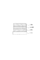
図1は、本発明の有機発光素子の一例を示す断面図である。図1は、基板1上に、陽極2、発光層3及び陰極4を順次設けた構成のものである。ここで使用する発光素子は、それ自体でホール輸送能、電子輸送能及び発光性の性能を単一で有している場合や、それぞれの特性を有する化合物を混ぜて使う場合に有用である。
FIG. 1 is a cross-sectional view showing an example of the organic light emitting device of the present invention. FIG. 1 shows a structure in which an anode 2, a
図2は、本発明の有機発光素子における他の例を示す断面図である。図2は、基板1上に、陽極2、ホール輸送層5、電子輸送層6及び陰極4を順次設けた構成のものである。この場合は、発光物質はホール輸送性かあるいは電子輸送性のいずれか、あるいは両方の機能を有している材料をそれぞれの層に用い、発光性の無い単なるホール輸送物質あるいは電子輸送物質と組み合わせて用いる場合に有用である。また、この場合、発光層3は、ホール輸送層5あるいは電子輸送層6のいずれかから成る。
FIG. 2 is a cross-sectional view showing another example of the organic light emitting device of the present invention. FIG. 2 shows a configuration in which an anode 2, a hole transport layer 5, an electron transport layer 6 and a cathode 4 are sequentially provided on a substrate 1. In this case, the light emitting material is either a hole transporting property or an electron transporting property, or a material having both functions is used for each layer, and it is combined with a simple hole transporting material or an electron transporting material having no light emitting property. This is useful when used. In this case, the
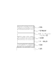
図3は、本発明の有機発光素子における他の例を示す断面図である。図3は、基板1上に、陽極2、ホール輸送層5、発光層3,電子輸送層6及び陰極4を順次設けた構成のものである。これは、キャリヤ輸送と発光の機能を分離したものである。そしてホール輸送性、電子輸送性、発光性の各特性を有した化合物と適時組み合わせて用いられ、極めて材料選択の自由度が増すとともに、発光波長を異にする種々の化合物が使用できるため、発光色相の多様化が可能になる。さらに、中央の発光層3に各キャリヤあるいは励起子を有効に閉じこめて、発光効率の向上を図ることも可能になる。
FIG. 3 is a cross-sectional view showing another example of the organic light emitting device of the present invention. FIG. 3 shows a structure in which an anode 2, a hole transport layer 5, a
図4は、本発明の有機発光素子における他の例を示す断面図である。図4は、図3に対して、ホール注入層7を陽極2側に挿入した構成であり、陽極2とホール輸送層5の密着性改善あるいはホールの注入性改善に効果があり、低電圧化に効果的である。 FIG. 4 is a cross-sectional view showing another example of the organic light emitting device of the present invention. FIG. 4 shows a configuration in which a hole injection layer 7 is inserted on the anode 2 side with respect to FIG. 3, and is effective in improving the adhesion between the anode 2 and the hole transport layer 5 or improving the hole injection property. It is effective.
図5は本発明の有機発光素子における他の例を示す断面図である。図5は、図3に対してホールあるいは励起子(エキシトン)が陰極4側に抜けることを阻害する層(ホール/エキシトンブロッキング層8)を、発光層3、電子輸送層6間に挿入した構成である。イオン化ポテンシャルの非常に高い化合物をホール/エキシトンブロッキング層8として用いる事により、発光効率の向上に効果的な構成である。
FIG. 5 is a cross-sectional view showing another example of the organic light-emitting device of the present invention. FIG. 5 shows a configuration in which a layer (hole / exciton blocking layer 8) that prevents holes or excitons (excitons) from escaping to the cathode 4 side is inserted between the light emitting
ただし、図1乃至図5はあくまでごく基本的な素子構成であり、本発明の化合物を用いた有機発光素子の構成はこれらに限定されるものではない。例えば、電極と有機層界面に絶縁性層を設ける、接着層あるいは干渉層を設ける、ホール輸送層がイオン化ポテンシャルの異なる2層から構成されるなど多様な層構成をとることができる。 However, FIGS. 1 to 5 are very basic device configurations, and the configuration of the organic light-emitting device using the compound of the present invention is not limited thereto. For example, various layer configurations such as providing an insulating layer at the interface between the electrode and the organic layer, providing an adhesive layer or interference layer, and the hole transporting layer are composed of two layers having different ionization potentials can be employed.
本発明に用いられる一般式[I]で示される化合物は、図1乃至図5のいずれの形態でも使用することができる。 The compound represented by the general formula [I] used in the present invention can be used in any form shown in FIGS.
特に、本発明の化合物を用いた有機層は、真空蒸着法や溶液塗布法などによって形成した層は結晶化などが起こりにくく経時安定性に優れている。 In particular, an organic layer using the compound of the present invention is excellent in stability over time because a layer formed by a vacuum deposition method or a solution coating method hardly causes crystallization.
本発明は、特に発光層の構成成分として、一般式[I]で示される化合物を用いるが、必要に応じてこれまで知られている低分子系およびポリマー系のホール輸送化合物、発光化合物あるいは電子輸送化合物などを一緒に使用することもできる。 In the present invention, the compound represented by the general formula [I] is used as a constituent component of the light emitting layer, and the low molecular weight and polymer type hole transport compounds, light emitting compounds or electrons known so far are used as necessary. A transport compound or the like can also be used together.
本発明で用いる基板としては、特に限定するものではないが、金属製基板、セラミックス製基板等の不透明性基板、ガラス、石英、プラスチックシート等の透明性基板が用いられる。 Although it does not specifically limit as a board | substrate used by this invention, Transparent substrates, such as opaque board | substrates, such as a metal board | substrate and a ceramic board | substrate, glass, quartz, a plastic sheet, are used.
また、基板にカラーフィルター膜、蛍光色変換フィルター膜、誘電体反射膜などを用いて発色光をコントロールする事も可能である。また、基板上に薄膜トランジスタ(TFT)を作成し、それに接続して素子を作成することも可能である。 It is also possible to control the color light by using a color filter film, a fluorescent color conversion filter film, a dielectric reflection film, or the like on the substrate. It is also possible to create a thin film transistor (TFT) on a substrate and connect it to create an element.
また、素子の光取り出し方向に関しては、ボトムエミッション構成(基板側から光を取り出す構成)および、トップエミッション(基板の反対側から光を取り出す構成)のいずれも可能である。 Further, regarding the light extraction direction of the element, either a bottom emission configuration (configuration in which light is extracted from the substrate side) or a top emission (configuration in which light is extracted from the opposite side of the substrate) is possible.
以下、実施例により本発明をさらに具体的に説明していくが、本発明はこれらに限定されるものではない。 EXAMPLES Hereinafter, the present invention will be described more specifically with reference to examples, but the present invention is not limited to these examples.
<実施例1>
例示化合物4の合成
<Example 1>
Synthesis of Exemplary Compound 4
a)中間体化合物1−1の合成
中間体は2,7−ジターシャリブチルフルオレン(シグマアルドリッチ社)を原料にして製造できる。さらに、ジメチル化することで中間体1−1が得られる。
b)例示化合物4の合成
200ml三ツ口フラスコに、化合物1−1、0.66g(1.70mmol)、化合物1−2、0.656g(2.00mmol)、トルエン120mlおよびエタノ−ル20mlを入れ、窒素雰囲気中、室温で攪拌下、炭酸ナトリウム10g/水100mlの水溶液を滴下し、次いでテトラキス(トリフェニルホスフィン)パラジウム(0)0.20g(0.170mmol)を添加した。77度に昇温し5時間攪拌した。反応後有機層をトルエンで抽出し無水硫酸ナトリウムで乾燥後、シリカゲルカラム(ヘプタン+トルエン混合展開溶媒)で精製し、例示化合物4(黄白色結晶)0.518g(収率60.1%)を得た。
質量分析法により、この化合物のM+である506.3を確認した。
a) Synthesis of Intermediate Compound 1-1 The intermediate can be produced using 2,7-ditertiarybutylfluorene (Sigma Aldrich) as a raw material. Furthermore, intermediate 1-1 is obtained by dimethylation.
b) Synthesis of Exemplified Compound 4 In a 200 ml three-necked flask, put Compound 1-1, 0.66 g (1.70 mmol), Compound 1-2, 0.656 g (2.00 mmol), 120 ml of toluene and 20 ml of ethanol, While stirring at room temperature in a nitrogen atmosphere, an aqueous solution of 10 g of sodium carbonate / 100 ml of water was added dropwise, and then 0.20 g (0.170 mmol) of tetrakis (triphenylphosphine) palladium (0) was added. The temperature was raised to 77 degrees and stirred for 5 hours. After the reaction, the organic layer was extracted with toluene, dried over anhydrous sodium sulfate and purified with a silica gel column (heptane + toluene mixed developing solvent) to obtain 0.518 g (yield 60.1%) of Exemplary Compound 4 (yellowish white crystals). Obtained.
By mass spectrometry, 506.3, which was M + of this compound, was confirmed.
また、1HNMR測定により、例示化合物4の構造を確認した。(図6)さらに、DSC示差走査熱量分析法により、融点287℃及びガラス転移点122℃を確認した。 In addition, the structure of Exemplary Compound 4 was confirmed by 1 HNMR measurement. (FIG. 6) Further, a melting point of 287 ° C. and a glass transition point of 122 ° C. were confirmed by DSC differential scanning calorimetry.
また、トルエン希薄溶液(1×10⁻⁵mol/l)での発光スペクトルは460nmにピークを持つ強い発光を確認した。 Further, the emission spectrum in a toluene dilute solution (1 × 10 −5 mol / l) confirmed strong emission having a peak at 460 nm.
<実施例2>
例示化合物22の合成
<Example 2>
Synthesis of Exemplified Compound 22
a)中間体1−3の合成
200ml三ツ口フラスコに、化合物1−1、12.0g(31.5mmol)、1,3−ビスジフェニルフォスフィノプロパンジクロロニッケル、1.70g(3.15mmol)、トルエン120mlおよびトリエチルアミン20mlを入れ、窒素雰囲気中、室温で攪拌下、テトラメチルピナコールボラン、13.7ml(94.5mmol)を滴下し、80度に昇温し8時間攪拌した。反応後、反応溶液を室温まで冷却し、1N塩化アンモニウム水溶液100mlを加え、30分攪拌した。有機層をトルエンで抽出し無水硫酸ナトリウムで乾燥後、シリカゲルカラム(ヘプタン+トルエン混合展開溶媒)で精製し、化合物1−3(白色結晶)9.34g(収率72.0%)を得た。
a) Synthesis of Intermediate 1-3 In a 200 ml three-necked flask, compound 1-1, 12.0 g (31.5 mmol), 1,3-bisdiphenylphosphinopropanedichloronickel, 1.70 g (3.15 mmol), toluene 120 ml and 20 ml of triethylamine were added, tetramethylpinacolborane, 13.7 ml (94.5 mmol) was added dropwise with stirring in a nitrogen atmosphere at room temperature, the temperature was raised to 80 ° C., and the mixture was stirred for 8 hours. After the reaction, the reaction solution was cooled to room temperature, 100 ml of 1N aqueous ammonium chloride solution was added, and the mixture was stirred for 30 minutes. The organic layer was extracted with toluene, dried over anhydrous sodium sulfate, and then purified with a silica gel column (heptane + toluene mixed developing solvent) to obtain 9.34 g of compound 1-3 (white crystals) (yield 72.0%). .
b)中間体1−5の合成
200ml三ツ口フラスコに、化合物1−4、1.68g(5.02mmol)、化合物1−3、2.31g(5.52mmol)、トルエン80mlおよびエタノ−ル40mlを入れ、窒素雰囲気中、室温で攪拌下、炭酸ナトリウム1g/水100mlの水溶液を滴下し、次いでテトラキス(トリフェニルホスフィン)パラジウム(0)0.579g(0.502mmol)を添加した。65度に昇温し5時間攪拌した。反応後有機層をトルエンで抽出し無水硫酸ナトリウムで乾燥後、シリカゲルカラム(ヘプタン+トルエン混合展開溶媒)で精製し、中間体1−5(黄白色結晶)1.84g(収率65.1%)を得た。
質量分析法により、この化合物のM+である561を確認した。
b) Synthesis of Intermediate 1-5 In a 200 ml three-necked flask, compound 1-4, 1.68 g (5.02 mmol), compound 1-3, 2.31 g (5.52 mmol), toluene 80 ml and ethanol 40 ml were added. In a nitrogen atmosphere, an aqueous solution of 1 g of sodium carbonate / 100 ml of water was added dropwise with stirring at room temperature, and then 0.579 g (0.502 mmol) of tetrakis (triphenylphosphine) palladium (0) was added. The temperature was raised to 65 degrees and stirred for 5 hours. After the reaction, the organic layer was extracted with toluene, dried over anhydrous sodium sulfate, and purified with a silica gel column (heptane + toluene mixed developing solvent) to obtain 1.84 g of intermediate 1-5 (yellowish white crystals) (yield 65.1%). )
By mass spectrometry, 561 which was M + of this compound was confirmed.
c)例示化合物22の合成
200ml三ツ口フラスコに、化合物1−5、1.10g(1.96mmol)、化合物1−2、0.709g(2.16mmol)、トルエン80mlおよびエタノ−ル40mlを入れ、窒素雰囲気中、室温で攪拌下、炭酸ナトリウム1.41g/水100mlの水溶液を滴下し、次いでテトラキス(トリフェニルホスフィン)パラジウム(0)0.227g(0.196mmol)を添加した。77度に昇温し5時間攪拌した。反応後有機層をトルエンで抽出し無水硫酸ナトリウムで乾燥後、シリカゲルカラム(ヘプタン+トルエン混合展開溶媒)で精製し、例示化合物22(黄白色結晶)0.920g(収率69%)を得た。
c) Synthesis of Exemplified Compound 22 In a 200 ml three-necked flask, put Compound 1-5, 1.10 g (1.96 mmol), Compound 1-2, 0.709 g (2.16 mmol), 80 ml of toluene and 40 ml of ethanol, While stirring at room temperature in a nitrogen atmosphere, an aqueous solution of 1.41 g of sodium carbonate / 100 ml of water was added dropwise, and then 0.227 g (0.196 mmol) of tetrakis (triphenylphosphine) palladium (0) was added. The temperature was raised to 77 degrees and stirred for 5 hours. After the reaction, the organic layer was extracted with toluene, dried over anhydrous sodium sulfate, and then purified with a silica gel column (heptane + toluene mixed developing solvent) to obtain 0.920 g of exemplified compound 22 (yellowish white crystals) (yield 69%). .
質量分析法により、この化合物のM+である715を確認した。
また、また、1HNMR測定により、例示化合物22の構造を確認した。(図7)
さらに、DSC示差走査熱量分析法により、融点287℃及びガラス転移点122℃を確認した。
Mass spectrometry confirmed 715, which is M + of this compound.
Moreover, the structure of the exemplary compound 22 was confirmed by 1 HNMR measurement. (Fig. 7)
Further, a melting point of 287 ° C. and a glass transition point of 122 ° C. were confirmed by DSC differential scanning calorimetry.
また、トルエン希薄溶液(1×10⁻⁵mol/l)での発光スペクトルは469nmにピークを持つ強い発光を確認した。 Moreover, the emission spectrum in the toluene dilute solution (1 × 10 −5 mol / l) confirmed strong emission having a peak at 469 nm.
<実施例3>
例示化合物5の合成
<Example 3>
Synthesis of Exemplified Compound 5
100ml三ツ口フラスコに、化合物1−1、0.39g(1.00mmol)、化合物1−6、0.530g(1.00mmol)、トルエン10mlおよびエタノ−ル50mlを入れ、窒素雰囲気中、室温で攪拌下、炭酸ナトリウム10g/水10mlの水溶液を滴下し、次いでテトラキス(トリフェニルホスフィン)パラジウム(0)0.06g(0.05mmol)を添加した。77度に昇温し5時間攪拌した。室温まで冷却後、析出した結晶をろ過し、得られた粗結晶をトルエン−エタノールより再結晶し、例示化合物5(淡黄白色結晶)0.120g(収率16.9%)を得た。 In a 100 ml three-necked flask, put Compound 1-1, 0.39 g (1.00 mmol), Compound 1-6, 0.530 g (1.00 mmol), 10 ml of toluene and 50 ml of ethanol, and stir at room temperature in a nitrogen atmosphere. Then, an aqueous solution of 10 g of sodium carbonate / 10 ml of water was dropped, and then 0.06 g (0.05 mmol) of tetrakis (triphenylphosphine) palladium (0) was added. The temperature was raised to 77 degrees and stirred for 5 hours. After cooling to room temperature, the precipitated crystals were filtered, and the resulting crude crystals were recrystallized from toluene-ethanol to obtain 0.120 g (yield 16.9%) of Exemplary Compound 5 (pale yellowish white crystals).
質量分析法により、この化合物のM+である708.4を確認した。また、1HNMR測定により、例示化合物5の構造を確認した。(図8)
また、トルエン希薄溶液(1×10⁻⁵mol/l)での発光スペクトルは435nmにピークを持つ強い発光を確認した。
Mass spectrometry confirmed 708.4, which is M + of this compound. In addition, the structure of Exemplary Compound 5 was confirmed by 1 HNMR measurement. (Fig. 8)
In addition, the emission spectrum of a diluted toluene solution (1 × 10 −5 mol / l) confirmed strong emission having a peak at 435 nm.
<実施例4>
図3に示す構造の有機発光素子を以下に示す方法で作成した。
<Example 4>
An organic light emitting device having the structure shown in FIG. 3 was prepared by the following method.
基板1としてのガラス基板上に、陽極2としての酸化錫インジウム(ITO)をスパッタ法にて120nmの膜厚で成膜したものを透明導電性支持基板として用いた。これをアセトン、イソプロピルアルコール(IPA)で順次超音波洗浄し、次いでIPAで煮沸洗浄後乾燥した。さらに、UV/オゾン洗浄したものを透明導電性支持基板として使用した。 What formed indium tin oxide (ITO) as an anode 2 with a film thickness of 120 nm on a glass substrate as a substrate 1 by a sputtering method was used as a transparent conductive support substrate. This was ultrasonically washed successively with acetone and isopropyl alcohol (IPA), then boiled and washed with IPA and then dried. Furthermore, what was UV / ozone cleaned was used as a transparent conductive support substrate.
正孔輸送材料として下記構造式3−1で示される化合物を用いて、濃度が0.1wt%となるようにクロロホルム溶液を調整した。 Using a compound represented by the following structural formula 3-1 as a hole transport material, a chloroform solution was prepared so that the concentration was 0.1 wt%.
この溶液を上記のITO電極上に滴下し、最初に500RPMの回転で10秒、次に1000RPMの回転で1分間スピンコートを行い膜形成した。この後10分間、80℃の真空オーブンで乾燥し、薄膜中の溶剤を完全に除去した。形成されたホール輸送層5の厚みは15nmであった。 This solution was dropped on the ITO electrode, and a film was formed by spin coating first at a rotation of 500 RPM for 10 seconds and then at a rotation of 1000 RPM for 1 minute. Thereafter, the film was dried in a vacuum oven at 80 ° C. for 10 minutes to completely remove the solvent in the thin film. The formed hole transport layer 5 had a thickness of 15 nm.
次に、ホール輸送層5の上に発光層3として第1の化合物として前記例示化合物4と、第2の化合物として下記構造式3−2を共蒸着(重量比10:90)して40nmの発光層3を設けた。蒸着時の真空度は1.0×10⁻⁴Pa、成膜速度は0.2nm/sec以上0.3nm/sec以下の条件で成膜した。
Next, on the hole transport layer 5, the exemplified compound 4 as the first compound as the
更に電子輸送層6として2、9−[2−(9,9‘−ジメチルフルオレニル)]−1、10−フェナントロリンを真空蒸着法にて30nmの膜厚に形成した。蒸着時の真空度は1.0×10⁻⁴Pa、成膜速度は0.2nm/sec以上0.3nm/sec以下の条件であった。 Further, 2,9- [2- (9,9′-dimethylfluorenyl)]-1,10-phenanthroline was formed as the electron transport layer 6 to a thickness of 30 nm by vacuum deposition. The degree of vacuum at the time of vapor deposition was 1.0 × 10 −4 Pa and the film formation rate was 0.2 nm / sec or more and 0.3 nm / sec or less.
次に、アルミリチウム(AlLi)を先ほどの有機層の上に、真空蒸着法により厚さ0.5nm形成し、更に真空蒸着法により厚さ150nmのアルミニウム膜を設け電子注入電極(陰極4)とする有機発光素子を作成した。蒸着時の真空度は1.0×10⁻⁴Pa、成膜速度は、フッ化リチウムは0.05nm/sec、アルミニウムは1.0nm/sec以上1.2nm/sec以下の条件で成膜した。 Next, aluminum lithium (AlLi) is formed on the previous organic layer by a thickness of 0.5 nm by a vacuum deposition method, and an aluminum film having a thickness of 150 nm is further provided by a vacuum deposition method to form an electron injection electrode (cathode 4). An organic light emitting device was produced. The degree of vacuum at the time of vapor deposition was 1.0 × 10 −4 Pa, the film formation rate was 0.05 nm / sec for lithium fluoride, and film formation was performed at 1.0 nm / sec to 1.2 nm / sec for aluminum. .
得られた有機EL素子は、水分の吸着によって素子劣化が起こらないように、乾燥空気雰囲気中で保護用ガラス板をかぶせ、アクリル樹脂系接着材で封止した。 The obtained organic EL device was covered with a protective glass plate in a dry air atmosphere and sealed with an acrylic resin adhesive so that the device did not deteriorate due to moisture adsorption.
この様にして得られた素子に、ITO電極(陽極2)を正極、Al電極(陰極4)を負極にして、4Vの印加電圧で、発光輝度450cd/m2、発光効率2.8lm/Wの青色の発光が観測された。 The device thus obtained was used with an ITO electrode (anode 2) as a positive electrode and an Al electrode (cathode 4) as a negative electrode, with an applied voltage of 4 V, an emission luminance of 450 cd / m 2 , and an emission efficiency of 2.8 lm / W. Blue emission was observed.
<実施例5>
図4に示す構造の有機発光素子を以下に示す方法で作成した。
<Example 5>
An organic light emitting device having the structure shown in FIG. 4 was prepared by the following method.
基板1としてのガラス基板上に、陽極2としての酸化錫インジウム(ITO)をスパッタ法にて120nmの膜厚で成膜したものを透明導電性支持基板として用いた。これをアセトン、イソプロピルアルコール(IPA)で順次超音波洗浄し、次いで純水で洗浄後真空オーブンで120℃で乾燥した。さらに、UV/オゾン洗浄したものを透明導電性支持基板として使用した。 What formed indium tin oxide (ITO) as an anode 2 with a film thickness of 120 nm on a glass substrate as a substrate 1 by a sputtering method was used as a transparent conductive support substrate. This was ultrasonically washed successively with acetone and isopropyl alcohol (IPA), then washed with pure water and then dried at 120 ° C. in a vacuum oven. Furthermore, what was UV / ozone cleaned was used as a transparent conductive support substrate.
ホール注入材料として下記構造式3−3で示される化合物を用いて、濃度が0.1wt%となるようにクロロホルム溶液を調整した。 Using a compound represented by the following structural formula 3-3 as a hole injection material, a chloroform solution was prepared so that the concentration was 0.1 wt%.
3−3
この溶液を上記のITO電極上に滴下し、最初に500RPMの回転で10秒、次に1000RPMの回転で40秒間スピンコートを行い膜形成した。この後10分間、80℃の真空オーブンで乾燥し、薄膜中の溶剤を完全に除去した。形成されたホール注入層7の厚みは15nmであった。
3-3
This solution was dropped on the ITO electrode, and a film was formed by spin coating first at a rotation of 500 RPM for 10 seconds and then at a rotation of 1000 RPM for 40 seconds. Thereafter, the film was dried in a vacuum oven at 80 ° C. for 10 minutes to completely remove the solvent in the thin film. The thickness of the formed hole injection layer 7 was 15 nm.
次に、ホール注入層7の上にさらに下記構造式3−4を蒸着し、厚さ15nmのホール輸送層5を設けた。 Next, the following structural formula 3-4 was further deposited on the hole injection layer 7 to provide a hole transport layer 5 having a thickness of 15 nm.
3−4
さらに、その上に発光層3として第1の化合物として前記例示化合物22と、第2の化合物として下記構造式3−2を共蒸着(重量比5:95)して30nmの発光層3を設けた。蒸着時の真空度は1.0×10⁻⁴Pa、成膜速度は0.1nm/sec以上0.2nm/sec以下の条件で成膜した。
3-4
Further, a 30 nm
更に電子輸送層6として2、9−[2−(9,9’−ジメチルフルオレニル)]−1、10−フェナントロリンを真空蒸着法にて30nmの膜厚に形成した。蒸着時の真空度は1.0×10⁻⁴Pa、成膜速度は0.1nm/sec以上0.2nm/sec以下の条件であった。 Further, 2,9- [2- (9,9′-dimethylfluorenyl)]-1,10-phenanthroline was formed as the electron transport layer 6 to a thickness of 30 nm by vacuum deposition. The degree of vacuum during vapor deposition was 1.0 × 10 −4 Pa, and the film formation rate was 0.1 nm / sec or more and 0.2 nm / sec or less.
次に、フッ化リチウム(LiF)を先ほどの有機層の上に、真空蒸着法により厚さ0.5nm形成し、更に真空蒸着法により厚さ150nmのアルミニウム膜を設け電子注入電極(陰極4)とする有機発光素子を作成した。蒸着時の真空度は1.0×10⁻⁴Pa、成膜速度は、フッ化リチウムは0.01nm/sec、アルミニウムは1.0nm/sec以上1.2nm/sec以下の条件で成膜した。 Next, lithium fluoride (LiF) is formed on the previous organic layer by a thickness of 0.5 nm by a vacuum deposition method, and an aluminum film having a thickness of 150 nm is further provided by a vacuum deposition method. Electron injection electrode (cathode 4) An organic light emitting device was created. The degree of vacuum during vapor deposition was 1.0 × 10 −4 Pa, the film formation rate was 0.01 nm / sec for lithium fluoride, and film formation was performed for 1.0 nm / sec to 1.2 nm / sec for aluminum. .
得られた有機EL素子は、水分の吸着によって素子劣化が起こらないように、乾燥空気雰囲気中で保護用ガラス板をかぶせ、アクリル樹脂系接着材で封止した。 The obtained organic EL device was covered with a protective glass plate in a dry air atmosphere and sealed with an acrylic resin adhesive so that the device did not deteriorate due to moisture adsorption.
この様にして得られた素子に、ITO電極(陽極2)を正極、Al電極(陰極4)を負極にして、4Vの印加電圧で、発光輝度104cd/m2、発光効率4.9lm/Wの青色の発光が観測された。 In the thus obtained device, with the ITO electrode (anode 2) as the positive electrode and the Al electrode (cathode 4) as the negative electrode, the emission luminance was 104 cd / m 2 and the emission efficiency was 4.9 lm / W at an applied voltage of 4V. Blue emission was observed.
<比較例2>
例示化合物4に代えて、下記に示す比較化合物4−1を用いた他は用いた他は実施例4と同様に素子を作成し、同様な評価を行ったところ、例示化合物4−1による発光を確認できなかった。
<Comparative example 2>
A device was prepared in the same manner as in Example 4 except that the comparative compound 4-1 shown below was used instead of the exemplified compound 4, and the same evaluation was performed. Could not be confirmed.
1 基板
2 陽極
3 発光層
4 陰極
5 ホール輸送層
6 電子輸送層
7 ホール注入層
8 ホール/エキシトンブロッキング層
DESCRIPTION OF SYMBOLS 1 Substrate 2
Claims (3)
Priority Applications (5)
| Application Number | Priority Date | Filing Date | Title |
|---|---|---|---|
| JP2006310380A JP4819655B2 (en) | 2006-04-27 | 2006-11-16 | 4-Arylfluorene compound and organic light-emitting device using the same |
| PCT/JP2007/058476 WO2007125809A1 (en) | 2006-04-27 | 2007-04-12 | 4-arylfluorene compound and organic light-emitting device using same |
| KR1020087028869A KR20090008411A (en) | 2006-04-27 | 2007-04-12 | 4-arylfluorene compound and organic light-emitting device using same |
| EP07741912A EP2013158A4 (en) | 2006-04-27 | 2007-04-12 | 4-arylfluorene compound and organic light-emitting device using same |
| US12/298,749 US8021767B2 (en) | 2006-04-27 | 2007-04-12 | 4-arylfluorene compound and organic light-emitting device using same |
Applications Claiming Priority (3)
| Application Number | Priority Date | Filing Date | Title |
|---|---|---|---|
| JP2006123784 | 2006-04-27 | ||
| JP2006123784 | 2006-04-27 | ||
| JP2006310380A JP4819655B2 (en) | 2006-04-27 | 2006-11-16 | 4-Arylfluorene compound and organic light-emitting device using the same |
Publications (3)
| Publication Number | Publication Date |
|---|---|
| JP2007314506A JP2007314506A (en) | 2007-12-06 |
| JP2007314506A5 JP2007314506A5 (en) | 2008-10-02 |
| JP4819655B2 true JP4819655B2 (en) | 2011-11-24 |
Family
ID=38655335
Family Applications (1)
| Application Number | Title | Priority Date | Filing Date |
|---|---|---|---|
| JP2006310380A Expired - Fee Related JP4819655B2 (en) | 2006-04-27 | 2006-11-16 | 4-Arylfluorene compound and organic light-emitting device using the same |
Country Status (5)
| Country | Link |
|---|---|
| US (1) | US8021767B2 (en) |
| EP (1) | EP2013158A4 (en) |
| JP (1) | JP4819655B2 (en) |
| KR (1) | KR20090008411A (en) |
| WO (1) | WO2007125809A1 (en) |
Families Citing this family (16)
| Publication number | Priority date | Publication date | Assignee | Title |
|---|---|---|---|---|
| JP2007308477A (en) * | 2006-04-20 | 2007-11-29 | Canon Inc | Compound and organic light-emitting device |
| JP5305919B2 (en) * | 2006-11-15 | 2013-10-02 | 出光興産株式会社 | Fluoranthene compound, organic electroluminescence device using the fluoranthene compound, and solution containing organic electroluminescence material |
| JP5361237B2 (en) * | 2007-05-16 | 2013-12-04 | キヤノン株式会社 | Benzo [a] fluoranthene compound and organic light-emitting device using the same |
| JP5361238B2 (en) * | 2007-05-16 | 2013-12-04 | キヤノン株式会社 | Benzo [a] fluoranthene compound and organic light-emitting device using the same |
| JP5441348B2 (en) | 2007-05-16 | 2014-03-12 | キヤノン株式会社 | Benzo [a] fluoranthene compound and organic light-emitting device using the same |
| JP5376857B2 (en) * | 2008-08-04 | 2013-12-25 | キヤノン株式会社 | Fused polycyclic compound and organic light emitting device using the same |
| EP2713415B1 (en) | 2008-12-26 | 2018-12-19 | Idemitsu Kosan Co., Ltd | Material for organic electroluminescent element, and organic electroluminescent element |
| US8941099B2 (en) | 2010-07-07 | 2015-01-27 | Universal Display Corporation | Organic light emitting device and materials for use in same |
| DE102010033778A1 (en) * | 2010-08-09 | 2012-02-09 | Merck Patent Gmbh | Polymers with carbazole structural units |
| DE102010033777A1 (en) * | 2010-08-09 | 2012-02-09 | Merck Patent Gmbh | Polymers with carbazole structural units |
| JP2014511025A (en) | 2011-02-11 | 2014-05-01 | ユニバーサル ディスプレイ コーポレイション | ORGANIC LIGHT EMITTING DEVICE AND MATERIAL FOR USE IN THE ORGANIC LIGHT EMITTING DEVICE |
| WO2012108881A1 (en) | 2011-02-11 | 2012-08-16 | Universal Display Corporation | Organic light emitting device and materials for use in same |
| KR20140009260A (en) | 2011-02-11 | 2014-01-22 | 유니버셜 디스플레이 코포레이션 | Organic light emitting device and materials for use in same |
| WO2012108879A1 (en) | 2011-02-11 | 2012-08-16 | Universal Display Corporation | Organic light emitting device and materials for use in same |
| JP6444046B2 (en) | 2013-04-03 | 2018-12-26 | キヤノン株式会社 | Organic compound and organic light emitting device |
| US20160181542A1 (en) | 2013-09-06 | 2016-06-23 | Idemitsu Kosan Co., Ltd. | Anthracene derivative and organic electroluminescent element using same |
Family Cites Families (23)
| Publication number | Priority date | Publication date | Assignee | Title |
|---|---|---|---|---|
| JP3767988B2 (en) | 1997-12-18 | 2006-04-19 | 三井化学株式会社 | Organic electroluminescence device |
| JP3792036B2 (en) | 1998-01-13 | 2006-06-28 | 三井化学株式会社 | Organic electroluminescence device |
| JP3884557B2 (en) | 1998-04-01 | 2007-02-21 | 三井化学株式会社 | Organic electroluminescence device |
| JP4996794B2 (en) | 2000-08-10 | 2012-08-08 | 三井化学株式会社 | Hydrocarbon compound, material for organic electroluminescence device, and organic electroluminescence device |
| US6929870B2 (en) | 2000-08-10 | 2005-08-16 | Mitsui Chemicals, Inc. | Hydrocarbon compounds, materials for organic electroluminescent elements and organic electroluminescent elements |
| JP4562884B2 (en) * | 2000-08-25 | 2010-10-13 | 出光興産株式会社 | Organic electroluminescence device |
| JP4224252B2 (en) * | 2001-04-19 | 2009-02-12 | Tdk株式会社 | Compound for organic EL element, organic EL element |
| CN1325449C (en) | 2001-04-19 | 2007-07-11 | Tdk株式会社 | Compound for organic el element and organic el element |
| JP4338367B2 (en) * | 2002-07-11 | 2009-10-07 | 三井化学株式会社 | Compound, organic electroluminescent element material, and organic electroluminescent element |
| JP4585750B2 (en) * | 2002-08-27 | 2010-11-24 | キヤノン株式会社 | Fused polycyclic compound and organic light emitting device using the same |
| JP3902993B2 (en) * | 2002-08-27 | 2007-04-11 | キヤノン株式会社 | Fluorene compound and organic light emitting device using the same |
| WO2005061656A1 (en) | 2003-12-19 | 2005-07-07 | Idemitsu Kosan Co., Ltd. | Light-emitting material for organic electroluminescent device, organic electroluminescent device using same, and material for organic electroluminescent device |
| JP4674454B2 (en) * | 2004-01-27 | 2011-04-20 | ソニー株式会社 | Organic light emitting material and organic electroluminescent device |
| JP4388391B2 (en) | 2004-02-27 | 2009-12-24 | 三井化学株式会社 | Fluorene compound and organic electroluminescence device containing the fluorene compound |
| JP4065547B2 (en) | 2004-04-12 | 2008-03-26 | キヤノン株式会社 | Fluorene compound and organic light emitting device using the same |
| JP4599142B2 (en) | 2004-11-26 | 2010-12-15 | キヤノン株式会社 | Organic light emitting device |
| DE102005040285A1 (en) * | 2005-08-25 | 2007-03-01 | Basf Ag | Organic LED for emitting white light comprises fluoranthene derivatives for emitting blue light as A component, and arylamine derivatives for emitting blue light as B component, useful in stationary screens such as computer screen |
| JP4659695B2 (en) | 2005-11-01 | 2011-03-30 | キヤノン株式会社 | Fluorene compound and organic light emitting device |
| JP5074754B2 (en) | 2006-03-31 | 2012-11-14 | キヤノン株式会社 | Novel compound and organic light emitting device using the same |
| JP2007314511A (en) | 2006-04-24 | 2007-12-06 | Canon Inc | Compound and organic light-emitting device |
| JP5294650B2 (en) | 2007-03-12 | 2013-09-18 | キヤノン株式会社 | Naphthalene compound and organic light emitting device using the same |
| JP4827775B2 (en) | 2007-03-13 | 2011-11-30 | キヤノン株式会社 | Electroluminescent device |
| JP5159164B2 (en) | 2007-05-14 | 2013-03-06 | キヤノン株式会社 | Benzo [ghi] fluoranthene derivative and organic light-emitting device using the same |
-
2006
- 2006-11-16 JP JP2006310380A patent/JP4819655B2/en not_active Expired - Fee Related
-
2007
- 2007-04-12 US US12/298,749 patent/US8021767B2/en not_active Expired - Fee Related
- 2007-04-12 EP EP07741912A patent/EP2013158A4/en not_active Withdrawn
- 2007-04-12 WO PCT/JP2007/058476 patent/WO2007125809A1/en active Application Filing
- 2007-04-12 KR KR1020087028869A patent/KR20090008411A/en not_active Application Discontinuation
Also Published As
| Publication number | Publication date |
|---|---|
| KR20090008411A (en) | 2009-01-21 |
| US8021767B2 (en) | 2011-09-20 |
| JP2007314506A (en) | 2007-12-06 |
| WO2007125809A1 (en) | 2007-11-08 |
| US20090134788A1 (en) | 2009-05-28 |
| EP2013158A1 (en) | 2009-01-14 |
| EP2013158A4 (en) | 2009-04-22 |
Similar Documents
| Publication | Publication Date | Title |
|---|---|---|
| JP4819655B2 (en) | 4-Arylfluorene compound and organic light-emitting device using the same | |
| KR101049328B1 (en) | 4-aminofluorene compound and organic light emitting device | |
| JP4865258B2 (en) | 1,8-naphthyridine compound and organic light-emitting device using the same | |
| JP4065547B2 (en) | Fluorene compound and organic light emitting device using the same | |
| JP4653061B2 (en) | Amine compound, organic light emitting device and blue organic light emitting device | |
| JP4659695B2 (en) | Fluorene compound and organic light emitting device | |
| JP4939207B2 (en) | Carbazole compound and organic light emitting device using the same | |
| JP5317414B2 (en) | Dibenzoanthracene compound and organic light-emitting device having the same | |
| US7923129B2 (en) | Carbazole derivative and organic light emitting device using the same | |
| EP2054360B1 (en) | Fused ring aromatic compound and organic light-emitting device using same | |
| JP2004107326A (en) | Condensed polycyclic compound and organic light-emitting element by using the same | |
| JP5153127B2 (en) | Amine compound and organic light emitting device | |
| KR20130121597A (en) | Using triphenylamine as hole transporting mateial and organic electroluminescent device using the same | |
| JP2007332127A (en) | Compound and organic light-emitting element | |
| KR101764908B1 (en) | 2-phenanthrene carbazole derivative compound and organic electroluminescent device including the same | |
| JP4950460B2 (en) | Organic light emitting device | |
| JP2008285450A (en) | Condensed ring aromatic compound and organic light-emitting element using the same | |
| JP5376857B2 (en) | Fused polycyclic compound and organic light emitting device using the same | |
| JP2008308449A (en) | Condensed-ring aromatic compound and organic electroluminescent element | |
| JP2007001879A (en) | 1, 9, 10-anthridine compound and organic light emitting device using the same | |
| JP2010138091A (en) | New indenobenzoanthracene compound | |
| KR101760774B1 (en) | Organic Light Emitting Material and Organic Light Emitting Diode Having The Same | |
| JP2009040723A (en) | Fluoranthene compound, and organic light emitting device using the same | |
| JP2014156454A (en) | Benzoindenochrysene compound and organic light emitting element made using the same |
Legal Events
| Date | Code | Title | Description |
|---|---|---|---|
| A521 | Request for written amendment filed |
Free format text: JAPANESE INTERMEDIATE CODE: A523 Effective date: 20080820 |
|
| A621 | Written request for application examination |
Free format text: JAPANESE INTERMEDIATE CODE: A621 Effective date: 20080820 |
|
| RD04 | Notification of resignation of power of attorney |
Free format text: JAPANESE INTERMEDIATE CODE: A7424 Effective date: 20100201 |
|
| RD01 | Notification of change of attorney |
Free format text: JAPANESE INTERMEDIATE CODE: A7421 Effective date: 20100630 |
|
| A131 | Notification of reasons for refusal |
Free format text: JAPANESE INTERMEDIATE CODE: A131 Effective date: 20110607 |
|
| A521 | Request for written amendment filed |
Free format text: JAPANESE INTERMEDIATE CODE: A523 Effective date: 20110808 |
|
| TRDD | Decision of grant or rejection written | ||
| A01 | Written decision to grant a patent or to grant a registration (utility model) |
Free format text: JAPANESE INTERMEDIATE CODE: A01 Effective date: 20110830 |
|
| A01 | Written decision to grant a patent or to grant a registration (utility model) |
Free format text: JAPANESE INTERMEDIATE CODE: A01 |
|
| A61 | First payment of annual fees (during grant procedure) |
Free format text: JAPANESE INTERMEDIATE CODE: A61 Effective date: 20110901 |
|
| FPAY | Renewal fee payment (event date is renewal date of database) |
Free format text: PAYMENT UNTIL: 20140909 Year of fee payment: 3 |
|
| FPAY | Renewal fee payment (event date is renewal date of database) |
Free format text: PAYMENT UNTIL: 20140909 Year of fee payment: 3 |
|
| LAPS | Cancellation because of no payment of annual fees |