US9848544B2 - Automated hydroponic greenhouse factory - Google Patents
Automated hydroponic greenhouse factory Download PDFInfo
- Publication number
- US9848544B2 US9848544B2 US14/414,121 US201314414121A US9848544B2 US 9848544 B2 US9848544 B2 US 9848544B2 US 201314414121 A US201314414121 A US 201314414121A US 9848544 B2 US9848544 B2 US 9848544B2
- Authority
- US
- United States
- Prior art keywords
- trays
- pool
- plants
- tray
- nutrient solution
- Prior art date
- Legal status (The legal status is an assumption and is not a legal conclusion. Google has not performed a legal analysis and makes no representation as to the accuracy of the status listed.)
- Active, expires
Links
Images


Classifications
-
- A—HUMAN NECESSITIES
- A01—AGRICULTURE; FORESTRY; ANIMAL HUSBANDRY; HUNTING; TRAPPING; FISHING
- A01G—HORTICULTURE; CULTIVATION OF VEGETABLES, FLOWERS, RICE, FRUIT, VINES, HOPS OR SEAWEED; FORESTRY; WATERING
- A01G31/00—Soilless cultivation, e.g. hydroponics
- A01G31/02—Special apparatus therefor
-
- A01G1/001—
-
- A—HUMAN NECESSITIES
- A01—AGRICULTURE; FORESTRY; ANIMAL HUSBANDRY; HUNTING; TRAPPING; FISHING
- A01G—HORTICULTURE; CULTIVATION OF VEGETABLES, FLOWERS, RICE, FRUIT, VINES, HOPS OR SEAWEED; FORESTRY; WATERING
- A01G13/00—Protecting plants
- A01G13/02—Protective coverings for plants; Coverings for the ground; Devices for laying-out or removing coverings
-
- A—HUMAN NECESSITIES
- A01—AGRICULTURE; FORESTRY; ANIMAL HUSBANDRY; HUNTING; TRAPPING; FISHING
- A01G—HORTICULTURE; CULTIVATION OF VEGETABLES, FLOWERS, RICE, FRUIT, VINES, HOPS OR SEAWEED; FORESTRY; WATERING
- A01G22/00—Cultivation of specific crops or plants not otherwise provided for
-
- A—HUMAN NECESSITIES
- A01—AGRICULTURE; FORESTRY; ANIMAL HUSBANDRY; HUNTING; TRAPPING; FISHING
- A01G—HORTICULTURE; CULTIVATION OF VEGETABLES, FLOWERS, RICE, FRUIT, VINES, HOPS OR SEAWEED; FORESTRY; WATERING
- A01G31/00—Soilless cultivation, e.g. hydroponics
Definitions
- the present invention relates to hydroponics and, more particularly, to innovative automated hydroponic systems and methods for raising commercially valuable plants.
- an apparatus for growing plants including: (a) a pool for a nutrient solution; (b) a sufficient number of substantially identical trays, for at least partial immersion in the nutrient solution, to be arranged in a plurality of rows within the pool such that each row includes at least one the tray and also includes a gap wide enough to receive one and only one of the trays from an adjacent the row, each tray being adapted to hold at least one of the plants so that roots of the at least one plant are at least partly immersed in the nutrient solution; (c) for each row, a mechanism for moving the at least one tray of the each row within the each row, thereby changing a location of the gap within the row relative to the at least one tray of the row; and (d) a mechanism for moving one of the at least one tray of each row into the gap of an adjacent the row.
- a method of growing plants including the steps of: (a) arranging, in a pool of a nutrient solution, a sufficient number of substantially identical trays to be arranged in three rows within the pool such that each row includes a plurality of the trays and also includes a gap wide enough to receive one and only one of the trays from an adjacent the row, each tray being adapted to bold at least one of the plants so that roots of the at least one plant are at least partly immersed in the nutrient solution; (b) planting at least one of the plants in each of the trays of only one of the rows, leaving the trays of the other rows as empty trays, thereby transforming the trays of the only one row into planted trays; and (c) exchanging the trays among the rows, only within the pool, so that the planted trays are located only in the other rows, with every tray that is adjacent to a planted tray being one of the empty trays.
- a tray for supporting at least one plant with roots thereof at least partly immersed in a nutrient solution, including a substantially parallelepipedal block having, for each plant, an aperture that extends from a top side of the tray to a bottom side of the tray, and having, on each long side thereof, at least one protrusion for preventing adhesion of the tray to an adjacent tray when the tray and the adjacent tray are at least partly immersed in the nutrient solution.
- a method of growing a plant including the steps of (a) suspending the plant so that roots of the plant are at least partly immersed in a nutrient solution having a depth of between about 4 centimeters and about 20 centimeters; and (b) causing the nutrient solution to flow past the roots.
- a method of growing a plant including the steps of: (a) suspending the plant so that the roots of the plant are at least partly immersed in a nutrient solution; and (b) using airlift pumping to cause the nutrient solution to flow past the roots.
- a device for growing a plant including: (a) a mechanism for suspending the plant so that the roots of the plant are at least partly immersed in a nutrient solution; and (b) an airlift pump for causing the nutrient solution to flow past the roots.
- a method of growing a plant including the steps of: (a) suspending the plant so that the roots of the plant are at least partly immersed in a nutrient solution; and (b) maintaining a concentration of dissolved oxygen in the nutrient solution at at least about 80% of saturation.
- a device for growing a plant including: (a) a mechanism for suspending the plant so that the roots of the plant are at least partly immersed in a nutrient solution; and (b) a mechanism for maintaining a concentration of dissolved oxygen in the nutrient solution at at least about 80% of saturation.
- a system for growing plants including: (a) a plurality of hydroponic units; and (b) a single manifold for sampling a respective nutrient solution of each unit, thereby providing a sample of the respective nutrient solution; and (c) a controller for: (i) measuring at least one property of each sample, and (ii) in response to the measuring, and via the manifold, adjusting the respective nutrient solution of which the each sample is a sample.
- a device for providing adjustable shade including: (a) a plurality of parallel linear support members; (b) substantially enclosing each support member: a flexible tube; and (c) an inflation mechanism for reversibly inflating each tube.
- a system for growing and harvesting plants including: (a) a bed, for growing the plants, that includes a mechanism for moving the plants to a side of the bed when the plants are ready for harvesting; and (b) a harvester, adapted to be positioned adjacent to the side of the bed, for harvesting the plants as the plants are moved by the mechanism to the side of the bed.
- a method of growing and harvesting plants including: (a) placing the plants in a bed wherein the plants grow until ready to be harvested; and (b) moving the plants within the bed to a side of the bed while using a mechanical harvester at the side of the bed to harvest the plants.
- a system for growing a plurality of plants including: (a) a plurality of substantially parallel troughs for supporting a nutrient solution; (b) an opaque flexible sheet having a plurality of apertures therein for supporting the plants; and (c) a roller for reversibly unrolling the flexible sheet parallel to the troughs and positioned relative to the troughs so that when the flexible sheet is unrolled the flexible sheet substantially covers at least a portion of the plurality of troughs, with each aperture above a respective the trough and sufficiently close to the trough that roots of a plant that is supported by the each aperture are at least partly immersed in the nutrient solution.
- a method of growing a plurality of plants including the steps of: (a) placing a nutrient solution in a plurality of substantially parallel troughs; (b) spreading a flexible opaque sheet, that includes a plurality of apertures for supporting the plants, above at least a portion of the troughs so that each aperture is above a respective the trough; and (c) inserting each of the plants in a respective one of the apertures so that the one plant is supported by the respective aperture with roots of the one plant at least partly immersed in the nutrient solution.
- a first aspect of the present invention is a rotating field system for growing plants.
- a basic apparatus of the first aspect includes a pool for a nutrient system, a plurality of substantially identical trays to be at least partially immersed in the pool, and mechanisms for moving the trays within the pool.
- Each tray is adapted to hold at least one of the plants so that the roots of the plant(s) are at least partly immersed in the nutrient solution.
- For each row there is a mechanism for moving the tray(s) of the row within the row to change the location of the gap within the row relative to the tray(s) of the row.
- the apparatus also includes a mechanism for moving one of the tray(s) of each row into the gap of an adjacent row.
- the apparatus includes enough trays for each row to include two or more trays.
- each tray is adapted to float in the nutrient solution.
- the trays could be supported in the pool on wheels or rollers.
- the mechanism for moving the trays of a row within that row moves the trays in only one direction within that row.
- these mechanisms are arranged to move the trays of adjacent rows in opposite directions.
- the tray that is moved from a row into the gap of an adjacent row is an end tray of the row from which the tray is moved.
- the apparatus includes at least three rows of trays, arranged so that at least one of the rows is between two other rows.
- the mechanism for moving trays between rows is operative to move trays of the at least one row to either or the two other rows.
- the apparatus also includes a harvester that is adapted to be positioned to an end of one of the rows, for harvesting the plant(s) that is/are held by the tray at that end of the row.
- a harvester that is adapted to be positioned to an end of one of the rows, for harvesting the plant(s) that is/are held by the tray at that end of the row.
- substantially identical trays are arranged in a pool of a nutrient solution.
- Each tray is adapted to hold one or more of the plants so that the roots of the plant(s) are at least partly immersed in the nutrient solution.
- One or more of the plants is/are planted in each tray of only one of the three rows, leaving the trays of the other rows as empty trays (i.e., trays that are empty of the plants), thereby transforming the trays of that one row into planted trays.
- the trays then are exchanged among the rows, only within the pool, so that the planted trays are located only in the two other rows, with every tray that is adjacent to a planted tray being an empty tray.
- the plants are sufficiently small to thrive despite being planted in adjacent trays.
- the trays are exchanged after the plants have grown sufficiently to require spacing apart of the adjacent trays in order for the plants to continue to thrive.
- the exchanging of the trays is effected by steps including moving one of the trays of one of the rows into the gap of an adjacent row.
- the exchanging results in the only one row being occupied only by empty trays. Then, one or more or the plants again are planted in each tray of the only one row.
- a basic tray for supporting one or more plants with the roots of the plant(s) at least partly immersed in a nutrient solution, includes a substantially parallelepipedal block that has two parallel long sides, two parallel short sides, a top side and a bottom side, and that also has, for each plant, an aperture that extends from the top side of the tray to the bottom side of the tray.
- Each long side of the block has one or more protrusions for preventing adhesion of the tray to an adjacent tray when the two trays are at least partly immersed in the nutrient solution.
- the block is made of a material, such as low-density polypropylene, whose density is such that the block floats in the nutrient solution.
- the tray includes a champfer at each lateral edge.
- the lateral edges are the edges where the long and short sides meet.
- each champfer is at an angle of between about 15° and about 25° relative to an adjacent side of the tray.
- the aperture(s) is/are arranged to support the plant(s), for example by the leaves of the plant(s) or by the roots of the plant(s).
- a third aspect of the present invention is a method for growing a plant.
- the plant is suspended so that the roots of the plant are at least partly immersed in a nutrient solution that is between about 4 centimeters and about 20 centimeters deep and that preferably includes dissolved oxygen at a saturation level of at least about 80%.
- the nutrient solution is caused to flow past the roots.
- the nutrient solution is between about 5 centimeters and about 6 centimeters deep.
- airlift pumping is used to cause the nutrient solution to flow past the roots.
- the airlift pumping is effected at a sufficiently high flow rate to achieve at least about 80% dissolved oxygen saturation of the nutrient solution.
- a fourth aspect of the present invention is a method and device for growing a plant.
- the plant is suspended so that the roots of the plant are at least partly immersed in a nutrient solution.
- Airlift pumping is used to cause the nutrient solution to flow past the roots.
- the device includes a mechanism for suspending the plant so that the roots of the plant are at least partly immersed in a nutrient solution and an airlift pump for causing the nutrient solution to flow past the roots.
- a fifth aspect of the present invention is a method and device for growing a plant.
- the plant is suspended so that the roots of the plant are at least partly immersed in a nutrient solution.
- the concentration of dissolved oxygen in the nutrient solution is maintained at at least about 80% of saturation
- the device includes a mechanism for suspending the plant so that the roots of the plant are at least partly immersed in a nutrient solution and a mechanism for maintaining the concentration of dissolved oxygen in the nutrient solution at at least about 80% of saturation.
- a sixth aspect of the present invention is a system for growing plants.
- a basic such system includes a plurality of hydroponic units, a single manifold for sampling a respective nutrient solution of each unit to provide a sample of each nutrient solution, and a controller for measuring at least one property, such as acidity, electrical conductivity or dissolved oxygen concentration, of each of the samples and, in response to the measuring, and via the manifold, adjusting the corresponding nutrient solution.
- the system also includes a mechanism for adjusting the temperature of each nutrient solution.
- the controller is operative to measure the temperatures of the samples and, in response to the measuring, and via the temperature adjusting mechanism, to adjust the temperatures of the corresponding nutrient solutions.
- a seventh aspect of the present invention is a device for providing adjustable shade.
- a basic such device includes a plurality of linear support members, such as the support wires of FIGS. 9A and 9B below.
- the device also include, for each support member, a flexible tube that substantially encloses that support member.
- the device also includes an inflation mechanism for reversibly inflating each tube.
- the tubes are opaque.
- the tubes are transparent, and the device also includes a reservoir, of a colloidal suspension of particles in a gas such as air, that is operatively associated with the inflation mechanism.
- the colloidal particles are for modifying an optical property of the tubes.
- the device also includes, for each tube, a weight for holding the tube in a substantially straight vertical orientation when the tube is uninflated.
- An eighth aspect of the present invention is a system and method for growing and harvesting plants.
- the plants are placed for growing in a bed that includes a mechanism for moving the plants to a side of the bed when the plants are ready for harvesting.
- the mechanism moves the plants to that side of the bed, where a mechanical harvester is used to harvest the plants. That the harvester is “mechanical”, here and in the first and ninth aspects of the present invention, excludes from the scope of the related attached claims a person who stands at the side of the bed and harvests the plants.
- a ninth aspect of the present invention is a nutrient film technique system and method for growing a plurality of plants.
- a basic system of the eight aspect includes a plurality of substantially parallel troughs for supporting a nutrient solution, an opaque flexible sheet that has a plurality of apertures for supporting the plants, and a roller for reversibly unrolling the flexible sheet parallel to the troughs. The roller is positioned relative to the troughs so that when the flexible sheet is unrolled the flexible sheet substantially covers at least a portion of the troughs, with each aperture above a respective trough and sufficiently close to the trough that the roots of a plant that is supported by that aperture are at least pertly immersed in the nutrient solution.
- the troughs are corrugations of a substantially rigid sheet such as a polymer-coated metal sheet.
- the system also includes a harvester that is adapted to be positioned adjacent to the roller.
- the harvester is for harvesting the plants that are supported by the apertures as the flexible sheet is rolled off of the troughs onto the roller.
- a nutrient solution is placed in a plurality of substantially parallel troughs.
- a flexible opaque sheet that includes a plurality of apertures, is spread above at least a portion of the troughs so that each aperture is above a respective trough.
- Each plant is inserted in a respective trough so that the plant is supported by its aperture with its roots at least partly immersed in the nutrient solution.
- the sheet is withdrawn from above the troughs in a direction substantially parallel to the troughs while withdrawing at least a portion of each plant from its aperture when the plant reaches an end of the trough in which the plant's roots have been at least partly immersed in the nutrient solution.
- FIGS. 1A-1C illustrate a basic rotating field system of the present invention with two rows of trays
- FIGS. 2A-2L illustrates how trays are rotated within a rotating field system with six rows of trays to insert empty trays between planted trays as needed;
- FIG. 2M shows that the six rows of FIGS. 2A-2L are six of the rows of an eight-bed water unit, with the other two rows being nursery rows;
- FIGS. 3A-3D illustrate preferred embodiments of a tray of the preceding FIGS.
- FIG. 4 shows one preferred embodiment of a protrusion of FIG. 3A ;
- FIG. 5 shows a nutrient solution circulation system for the eight-bed water unit of FIG. 2M ;
- FIGS. 6 and 7 illustrate hardware for nutrient solution temperature regulation
- FIG. 8 illustrates a monitoring and control system of a multi-unit rotating field system
- FIGS. 9A and 9B illustrate an array of inflatable tubes for shading a bed of a rotating field system
- FIG. 10 shows a harvesting machine that is usable with the rotating field system or with the nutrient film technique system
- FIGS. 11 and 12 illustrates the nutrient film technique system of the present invention.
- the motivation for the basic rotating field system of the present invention is to create a conveyor system and mechanism to automatically rotate trays that bear plants in a growing bed in order to enable, planting, spacing, inspecting, treating and harvesting at the end or ends of the bed, thus eliminating the need for walkways between the beds.
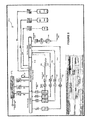
- FIGS. 1A-1C illustrate the basic components of a basic rotating field system 10 of the present invention.
- FIG. 1A is a perspective view of system 10 .
- FIGS. 1B and 1C are cross-sectional view of system 10 along cut A-A.
- System 10 is arranged so that trays 12 are rotated automatically, inside a water bed 14 (which is an example of the “pool” recited in the appended claims) as trays 12 float on a nutrient solution 16 in bed 14 .
- the use of such flotation allows a reliable, low maintenance, cost efficient solution and eliminates the need for use of beatings, shafts, sliding mechanisms and other mechanical fixtures for causing linear motion of trays 12 .
- Bed 14 includes a separation barrier (not shown) that allows for two rows 18 of trays 12 , one row 18 on each side of the barrier.
- Two pneumatic pistons 20 Y-pistons
- Y-pistons push respective rows 18 of trays 12 in opposite Y-directions.
- That row 18 Prior to movement of a row 18 by Y-piston 20 of that row 18 , that row 18 includes a gap 22 where one tray 12 is missing. This situation is illustrated in FIG. 1B for the right-side row 18 of FIG. 1A .
- FIGS. 2A-2L illustrate an enhanced rotating field system 30 that uses system 10 as its basic building block.
- the motivation for system 30 is to do the spacing of the plants automatically. Plants takes significantly less growing area as they build their biomass in their young growing stage, and thus need more growing area in their later growing stage. In order to utilize the growing area better, and increase the yields per square meter, plants are spaced differently during stages of their growth cycle.
- System 10 automatically rotates trays 12 that carry the plants within bed 14 , trays 12 never leave the single bed 14 and are only rotated within bed 14 .
- the spacing can only be done manually, at one of the ends of bed 14 , during the rotation.
- System 30 automatically, preferably using the same pneumatic pistons 20 and 26 , both rotates trays 18 within a single bed as needed and moves trays 18 between neighboring beds in order to space the plants by inserting an empty tray 18 from a neighboring bed in-between trays 18 whose plants need spacing.
- FIGS. 2A-2L show a growing and harvesting cycle in six adjacent beds (each with its own single row 18 of trays 12 ) of a water unit 14 (which also is an example of the “pool” recited in the appended claims).
- the beds are labeled A-F from upper left to lower right.
- FIG. 2A shows beds C and D fully occupied by trays 12 planted with immature plants. Trays 12 of beds A, B, E and F are empty. Beds A, B, E and F are ready to receive trays 12 from beds C and D and to space those trays 12 for further growth of the plants.
- FIG. 2B shows the plants of bed C sufficiently mature to be moved to beds A and B for further growth.
- FIG. 2C shows a planted tray 12 being moved from bed C to bed B while an empty tray 12 is moved from bed B to bed A.
- an empty tray 12 is moved from bed B to bed C and beds A and B are rotated, to put two empty trays 12 behind the planted tray 12 in bed B.
- FIG. 2D shows a second tray 12 being moved from bed C to bed B while an empty tray 12 is moved from bed B to bed C. Note the two empty trays 12 in bed B between the two planted trays 12 .
- an empty tray 12 is moved from bed B to bed C and beds A and B are rotated to put two empty trays 12 behind the second planted tray 12 in bed B.
- FIG. 2E shows the situation after three planted trays 12 have been moved out of bed C.
- the first tray 12 that was moved out of bed C is being moved from bed B to bed A.
- the second and third trays 12 that were moved from bed C are in bed B. All three trays 12 that have been moved from bed C have been replaced in bed C by empty trays 12 .
- FIG. 2F shows the situation after four planted trays 12 have been moved out of bed C.
- the first tray 12 that was moved out of bed C has been moved to bed A.
- the second tray 12 that was moved out of bed C is being moved from bed B to bed A.
- the third and fourth trays 12 that were moved from bed C are in bed B. All four trays 12 that have been moved from bed C have been replaced in bed C by empty trays 12 .
- FIG. 2G shows the situation after all but one of the planted trays 12 have been moved from bed C to beds A and B. Beds A and B are being rotated to bring the fourth planted tray 12 from bed B to bed A.
- FIG. 2H shows the situation after all eight planted trays 12 have been moved from bed C to beds A and B.
- beds A and B has four planted trays 12 separated by single empty trays 12 .
- FIG. 2I shows beds D, E and F.
- the empty trays 12 in beds C and D are ready to receive new plants.
- FIG. 2J shows beds C and D after replanting.
- FIG. 2K shows the situation after continued growth in all six beds. The plants in beds A, B, E and F are ready for harvesting.
- FIG. 2L shows the situation after the plants in beds A, B, E and F have been harvested.
- the plants in beds C and D have grown to the point of being ready to be moved to beds A, B, E and F for further growth.
- FIG. 2M shows that water unit 14 of FIGS. 2A-2L actually includes eight beds, with the two leftmost beds being used as a nursery.
- FIG. 2M also presents a calculation of the expected yield of a greenhouse with fifteen such water units 14 .
- FIG. 2M illustrates how the yield of a greenhouse of the present invention, per unit area, is increased by adapting the inter-plant spacing to the size of the plants, rather than using only the largest needed inter-plant spacing as is done conventionally.
- Trays 12 are made of a low-density polymer foam such as polystyrene foam. Trays 12 serve the following functions:
- FIGS. 3A-3D illustrate preferred embodiments of a tray 12 .
- FIG. 3A is a perspective view of one preferred embodiment of a tray 12 .
- FIG. 3B is a top view of a similar preferred embodiment of tray 12 .
- These embodiments are substantially parallelepipedal blocks of polystyrene foam with apertures 32 , for holding plants, that extend from the top surface 34 of the block to the bottom surface (not shown) of the block. The long 38 and short 40 lateral sides of the block meet at champfers 44 .
- FIGS. 3C and 3D are cross sectional views of two other preferred variants of a tray 12 , showing two kinds of apertures 32 that extend from the top surfaces 34 of these trays 12 to the bottom surfaces 36 of these trays 12 .
- Apertures 32 of the variant of FIG. 3C support their plants by the leaves of the plants.
- Apertures 32 of the variant of FIG. 3D supports the plants by their stems.
- Trays 12 float in the water-based nutrient solution 16 of the beds, with their long sides 38 parallel and adjacent. Absent lateral protrusions 42 from long sides 38 (shown in FIG. 3A ), the water would tend to form adhesive films on long sides 38 of trays 12 that would cause trays 12 to stick together and that would inhibit the tray rotation that is illustrated in FIGS. 2A-2L .
- Protrusions 42 space trays 12 apart, preferably ten centimeters apart, to prevent sticking.
- FIG. 4 shows one preferred embodiment of such a protrusion 42 : a rigid insert, fabricated separately from tray, for insertion in a slot 46 in long side 38 . ( FIG.
- protrusion 42 is smooth and/or is made of a low friction material such as TeflonTM.
- trays 12 are fabricated with integral protrusions 42 .
- integral protrusions 42 are made of the same material as these trays 12 , trays 12 with protrusions 42 have much lower areas of mutual contact than trays 12 with smooth sides 38 and so do not stick together appreciably.
- the edges of trays 12 where lateral sides 38 and 40 meet are chamfered because the motion of pistons 20 and 26 may deviate from exact rectilinear motion by up to about 5 degrees. Champfers 44 also help to keep trays 12 from sticking together.
- the champfer angles a and b shown in FIG. 3B preferably are between 15° and 25°.
- the plants can be supported either from their bottom or from their sides.
- the hydroponic technology of the present invention is a hybrid of Deep Water Culture (DWC) and Nutrient Film Technique (NFT)
- Deep Water Culture also referred to in the prior art as “floating raft hydroponics”—uses deep water bed typically on the order of one foot deep, containing all the dissolved nutrients required for plant growth. This nutrient solution is re-circulated past the bare roots of the plants. This technique has high productions costs and has problems with root disease due to lack of sufficient dissolved oxygen.
- NFT Nutrient Film Technique
- the hydroponic system and technique of the present invention is a hybrid of DWC and NFT that combines the all the benefits of DWC and NFT while eliminating almost all the problems.
- the system of the present invention uses water beds that are deep enough (4 to 20 cm; preferably 5-6 cm) to enable temperature regulation and stability of nutrient solution 16 but not so deep as to prevent the supply of sufficient dissolved oxygen in nutrient solution 16 .
- Nutrient solution 16 is circulated on a per-unit basis.
- the beds are oriented north-south (so the long direction of trays 12 , the “X-direction” of FIG. 1A , is east-west and the “Y-direction” of FIG. 1A is north-south) and nutrient solution 16 circulates one way (e.g. north to south) in odd-numbered beds and the other way (e.g. south to north) in even-numbered beds.
- the pumping system used is airlift pumping. Airlift pumping is used routinely in aquaculture but has not been used heretofore in hydroponics.
- FIG. 5 illustrate the airlift pumping system of the present invention.
- FIG. 5 shows a nutrient solution circulation system 50 for two adjacent beds of the eight-bed water unit of FIG. 2M .
- inlet tables 52 At the bases of the southern half of the western bed and at the bases of the northern half of the eastern bed are respective inlet tables 52 .
- outlet tables 54 At the bases of the southern half of the eastern bed and at the bases of the northern half of western bed are respective outlet tables 54 .
- Conventional airlift pumps 60 pump nutrient solution 16 to inlet tables 52 via inlet pipes 56 .
- Nutrient solution 16 returns to airlift pumps 60 from outlet tables 54 via outlet pipes 58 .
- the overall circulation of nutrient solution 16 is east to west in the northern halves of the two beds, north to south within the western bed, west to east in the southern halves of the two beds, and south to north within the eastern bed.
- the airlift pumping must be performed at a sufficiently high flow rate to achieve at least 80% O 2 saturation of nutrient solution 16 .
- Merely bubbling air through water does not achieve this degree of saturation because the high surface tension of the bubble surface inhibits dissolution of the air in the water. It is believed that microturbulence at the bases of trays 12 , especially at the openings of apertures 32 , causes bursting of the bubbles and consequent efficient solution of oxygen in nutrient solution 16 .
- the cross section of the flowing nutrient solution 16 is about 1 m wide (the width of a tray 12 ) ⁇ 5 cm deep and the flow rate through this cross section is about 6 to 8 cubic meters per hour.
- FIGS. 6 and 7 illustrate some of the hardware that is used for regulating the temperature of the nutrient solution of a bed.
- FIG. 6 shows a bed 14 whose nutrient solution 16 is heated by a hot water radiator 62 that receives hot water via a hot water inlet 64 .
- FIG. 7 shows a cooling tower that is used to cool nutrient solution 16 of a unit. Air is blown upward past a downward spray of nutrient solution 16 . Because nutrient solution 16 is corrosive, the inside surfaces of the tower that come in contact with nutrient solution 16 are coated with a liner made of a polymer such as polyethylene.
- a monitoring and control system 70 of a multi-unit system is illustrated in FIG. 8 .
- a central controller and data logger 72 samples nutrient solution 16 of each unit separately via a respective bypass pipe 74 . Missing water and nutrients, and acid for adjusting pH, are injected to the unit as needed. (In FIG. 8 , “Alfa” and “Beta” are concentrated nutrient solutions, and the “Air Bleeder” is used for monitoring and controlling dissolved oxygen content.) Controller 72 also synchronizes the movement of pistons 20 and 26 .
- each hydroponic water unit has been controlled by its own controller.
- the redundancy of having separate sensors, separate pumps and a separate controller for each unit is eliminated by providing a central controller 72 and an associated manifold 76 from which respective bypass pipes 74 branch out to the various units.
- Each bypass pipe 74 is provided with a pump (pumps P 1 through Pn in FIG. 8 ) that is controlled by central controller 72 .
- central controller 72 opens the valve 78 associated with that unit to obtain a sample of the unit's nutrient solution 16 .
- Natural ambient lighting is used to grow the plants.
- the system is housed in a transparent or semitransparent building such as a greenhouse or a screen house.
- Above beds 14 of each unit is an array 80 of east-west oriented flexible inflatable tubes 82 that are illustrated in perspective view and in cross-section in FIGS. 9A and 9B .
- FIG. 9A shows tubes 82 as fully inflated.
- FIG. 9B shows tubes 82 as deflated.
- Support wires 84 suspend tubes 82 above beds 14 .
- Weight wires 86 pull deflated tubes 82 vertically flat, as shown in FIG. 9B .
- Tubes 82 are inflated by air to the degree needed for thermal screening (e.g. at night) and illumination control.
- Additional illumination control is obtained by using a colloidal suspension of particles such as smoke particles in the air that is used to inflate the tubes.
- Colored particles are used to control the spectrum of the light that illuminates the plants. For example, green light, that is not used in photosynthesis and may contribute to excessive heating of the greenhouse, may be filtered out.
- a system of tilting shutters is used.
- the shutters are closed at night and are opened in the daytime at a tilt that changes with the angle at which the sun is shining.
- Planting and harvesting are done either manually or automatically.
- One method of automatic planting and harvesting is robotic, as described in U.S. Pat. No. 6,508,033, which patent is incorporated by reference for all purposes as if fully set forth herein.
- Another method of automatic harvesting is as follows:
- FIG. 10 shows a harvesting machine 90 that is usable with the rotating field system and method described above or with an automated NFT bed system as described below to automatically harvest leafy vegetables and other plants to be packed in bulk.
- Machine 90 has a set of knives 92 and a set of transport mechanisms which extend on a transverse frame.
- the frame is mountable on or near the rotating field system units or near the automated NFT bed system.
- the rotating field system or the automated NFT bed system is used to bring the harvested crop to machine 90 for harvesting.
- Knives 92 are operated by an electric motor.
- An electric air blower 96 and a conveyer can be the transport mechanisms used to move the cut leaves or plants into a collecting container 94 .
- Harvesting machine 90 is displaceable on or near a hydroponics growing bed 14 .
- Harvesting machine 90 includes a frame, having working mechanisms and a structure supporting the working mechanisms.
- the frame further has a set of mounts and a set of placement calibrating mechanisms extending at least approximately parallel to the growing bed plane, permitting a modification of the vertical position of the frame; a set of knives 92 powered by an electric motor for cutting the crop; connected to the structure by means that allow a modification of the vertical position of knives 92 , two spaced apart first wheels extending when considering the working direction behind the working tools allowing a modification of the vertical position of the first wheels in relation to the body, the first wheels being in contact with the ground or the sides of the bed or a rail set on the ground or connected to the bed during working in order to support the body during working.
- Plants that can be grown in the system of the present invention include: lettuce cos romaine, lettuce iceberg, lettuce lollorosa, lettuce butterhead, lettuce (curly leaf vars.), Chinese leaves (Chinese cabbage), chives, arugula, rocket, spring onions, pac-choy, mint leaves, dill, coriander, sweet basil, opal basil, rosemary, sage, tarragon, parsley (curly), parsley (flat), lemon grass and spinach.
- NFT systems use individually fabricated troughs or gutters, usually formed from extruded plastic, and tilted at an angle of 3° to 5° to allow the nutrient solution to flow past plants that are planted in a growth medium such as peat moss within the gutters.
- the NFT system of the current invention makes use of a corrugated metal sheet to create gutter-shaped troughs in a more cost-efficient way.
- the sheet is coated with a polymeric material to prevent corrosion by the nutrient solution.
- FIG. 11 shows an NFT system of the present invention: a gently (3° to 5°) tilted, polymer-coated corrugated metal sheet 102 above which is rolled out an opaque plastic sheet 106 with apertures 108 . That sheet 106 is opaque prevents light from striking the water-nutrient film in the troughs 104 of sheet 106 and promoting the growth of algae. Plants 110 are planted in/through apertures 108 .
- FIG. 12 shows that sheet 106 is rolled out from a roller 112 .
- sheet 106 is rolled back onto roller 112 and plants 110 are harvested as they approach roller 112 . Then sheet 106 is rolled back out and replanted.
- Rolling out sheet 106 for planting and rolling sheet 106 back for harvesting allows the workers to stand at or behind the roller to do the planting and the harvesting. With no need for aisles for the workers to walk along past sheet 106 , the NFT system of the present invention economizes on both the cost of labor and the cost of real estate.
- FIG. 12 shows sheet 106 rolled out from the bottom of roller 112 .
- sheet 106 is rolled out from the top of roller 112 .
- harvesting machine 90 can be moved up to the side of roller 112 opposite sheet 102 , to harvest plants 110 as plants 110 come in over the top of roller 112 .
Priority Applications (1)
| Application Number | Priority Date | Filing Date | Title |
|---|---|---|---|
| US14/414,121 US9848544B2 (en) | 2012-07-11 | 2013-07-01 | Automated hydroponic greenhouse factory |
Applications Claiming Priority (3)
| Application Number | Priority Date | Filing Date | Title |
|---|---|---|---|
| US201261670147P | 2012-07-11 | 2012-07-11 | |
| US14/414,121 US9848544B2 (en) | 2012-07-11 | 2013-07-01 | Automated hydroponic greenhouse factory |
| PCT/IB2013/055378 WO2014009842A2 (en) | 2012-07-11 | 2013-07-01 | Automated hydroponic greenhouse factory |
Related Parent Applications (1)
| Application Number | Title | Priority Date | Filing Date |
|---|---|---|---|
| PCT/IB2013/055378 A-371-Of-International WO2014009842A2 (en) | 2012-07-11 | 2013-07-01 | Automated hydroponic greenhouse factory |
Related Child Applications (1)
| Application Number | Title | Priority Date | Filing Date |
|---|---|---|---|
| US15/817,349 Continuation US10980198B2 (en) | 2012-07-11 | 2017-11-20 | Automated hydroponic greenhouse factory |
Publications (2)
| Publication Number | Publication Date |
|---|---|
| US20150150202A1 US20150150202A1 (en) | 2015-06-04 |
| US9848544B2 true US9848544B2 (en) | 2017-12-26 |
Family
ID=49916605
Family Applications (3)
| Application Number | Title | Priority Date | Filing Date |
|---|---|---|---|
| US14/414,121 Active 2034-02-17 US9848544B2 (en) | 2012-07-11 | 2013-07-01 | Automated hydroponic greenhouse factory |
| US15/817,349 Active 2034-05-14 US10980198B2 (en) | 2012-07-11 | 2017-11-20 | Automated hydroponic greenhouse factory |
| US16/942,952 Abandoned US20210045302A1 (en) | 2012-07-11 | 2020-07-30 | Automated hydroponic greenhouse factory |
Family Applications After (2)
| Application Number | Title | Priority Date | Filing Date |
|---|---|---|---|
| US15/817,349 Active 2034-05-14 US10980198B2 (en) | 2012-07-11 | 2017-11-20 | Automated hydroponic greenhouse factory |
| US16/942,952 Abandoned US20210045302A1 (en) | 2012-07-11 | 2020-07-30 | Automated hydroponic greenhouse factory |
Country Status (8)
| Country | Link |
|---|---|
| US (3) | US9848544B2 (ja) |
| EP (1) | EP2871934A4 (ja) |
| JP (1) | JP6414824B2 (ja) |
| CN (1) | CN104780755A (ja) |
| AU (1) | AU2013288328B2 (ja) |
| CA (1) | CA2876425A1 (ja) |
| IL (1) | IL236652B (ja) |
| WO (1) | WO2014009842A2 (ja) |
Cited By (7)
| Publication number | Priority date | Publication date | Assignee | Title |
|---|---|---|---|---|
| US20160192607A1 (en) * | 2013-08-14 | 2016-07-07 | Yugenkaisha Japan Tsusyo | Hydroponic cultivation system, and plant factory comprising hydroponic cultivation system and expanded polystyrene foam greenhouse |
| US20170099789A1 (en) * | 2015-10-08 | 2017-04-13 | Chaz Shelton | Systems, Methods, and Devices for Growing and Harvesting Produce |
| USD932345S1 (en) | 2020-01-10 | 2021-10-05 | AVA Technologies Inc. | Plant pod |
| USD932346S1 (en) | 2020-01-10 | 2021-10-05 | AVA Technologies Inc. | Planter |
| US20220256792A1 (en) * | 2019-06-27 | 2022-08-18 | W. L. Gore & Associates, Inc. | Cultivation systems for seaweeds |
| US11553656B2 (en) | 2019-04-30 | 2023-01-17 | AVA Technologies Inc. | Gardening apparatus |
| WO2023003760A1 (en) * | 2021-07-23 | 2023-01-26 | Iron Ox, Inc. | Apparatus for control and distribution of nutriated water in an automated agricultural facility |
Families Citing this family (20)
| Publication number | Priority date | Publication date | Assignee | Title |
|---|---|---|---|---|
| CA2876425A1 (en) | 2012-07-11 | 2014-01-16 | Growponics Greenhouse Technology Ltd. | Automated hydroponic greenhouse factory |
| EP2919579B1 (en) * | 2012-11-13 | 2020-04-15 | Jalmaja Holding B.V. | Growing system and method for growing plants on water |
| DK2941633T3 (da) | 2013-01-04 | 2024-04-02 | Meso Scale Technologies Llc | Assayapparater, fremgangsmåder og reagenser |
| AU2015336893A1 (en) | 2014-10-21 | 2017-05-18 | Avid Growing Systems Inc. | System, apparatus and method for growing marijuana |
| US20160235022A1 (en) * | 2015-02-12 | 2016-08-18 | Cody YEAGER | Seed starter |
| US10485193B2 (en) | 2015-05-28 | 2019-11-26 | Robert V. Neuhoff, JR. | Automated hydroponics system and method |
| CN106508648B (zh) * | 2015-09-11 | 2020-01-14 | 爱勒康农业科技有限公司 | 用于培育无土栽培植物的托盘组件 |
| CN105613248A (zh) * | 2016-02-20 | 2016-06-01 | 彭昊 | 一种多用水培植物盆及使用方法 |
| WO2017185064A1 (en) | 2016-04-21 | 2017-10-26 | Eden Works, Inc. (Dba Edenworks) | Stacked shallow water culture (sswc) growing systems, apparatus and methods |
| DE102016121126B3 (de) * | 2016-11-04 | 2018-01-18 | Farmers Cut GmbH | Klimatisch abgeschlossene Klimazelle zur Aufzucht von Pflanzen in Innenräumen |
| WO2018107176A1 (en) | 2016-12-09 | 2018-06-14 | Eden Works, Inc. (Dba Edenworks) | Methods systems and apparatus for cultivating densely seeded crops |
| US11540451B2 (en) * | 2018-02-13 | 2023-01-03 | Logiqs B.V. | Product holder assembly |
| CN108901806B (zh) * | 2018-07-11 | 2020-10-27 | 福建省中科生物股份有限公司 | 一种植物水培装置及植物水培方法 |
| WO2020028463A1 (en) * | 2018-08-02 | 2020-02-06 | Drexel University | An urban in-home system for growing fruits and vegetables |
| CN109607797B (zh) * | 2018-12-14 | 2021-10-08 | 河海大学设计研究院有限公司 | 多功能生态浮床 |
| CN110122399B (zh) * | 2019-05-20 | 2024-03-19 | 福建省淡水水产研究所 | 一种大刺鳅简易式循环水养殖系统及方法 |
| CN112868434B (zh) * | 2021-04-08 | 2023-08-15 | 张爱民 | 智能全自动无人水漂浮托盘式固体种植基质植物工厂 |
| CN114041412B (zh) * | 2021-11-09 | 2023-04-14 | 山东省科学院高新技术产业(中试)基地(山东省科学院留学人员创业园) | 一种水生植物实验养殖装置 |
| US11641812B1 (en) | 2021-12-02 | 2023-05-09 | Phat Panda LLC | Apparatus and system for improving consistent spacing between plant growing areas and for moving same |
| TW202341857A (zh) * | 2022-02-28 | 2023-11-01 | 日商電裝股份有限公司 | 植物栽培裝置 |
Citations (39)
| Publication number | Priority date | Publication date | Assignee | Title |
|---|---|---|---|---|
| JPS457937Y1 (ja) | 1966-08-30 | 1970-04-15 | ||
| US4037360A (en) | 1974-12-30 | 1977-07-26 | Farnsworth Robert S | Raft apparatus for growing plants by means of water culture |
| US4041641A (en) * | 1975-08-08 | 1977-08-16 | Albert Louis Dietz | Process of growing plants within an enclosure |
| US4253271A (en) * | 1978-12-28 | 1981-03-03 | Battelle Memorial Institute | Mass algal culture system |
| US4290229A (en) * | 1979-10-04 | 1981-09-22 | Masahiro Miura | Installation for cultivation of crops on water |
| US4312152A (en) * | 1980-06-09 | 1982-01-26 | Agrownautics, Inc. | Buoyant support structure and system and method using structure for water culture of plants |
| US4355484A (en) * | 1981-09-08 | 1982-10-26 | Mandish Theodore O | Hydroponic tray and method of manufacture |
| US4382348A (en) * | 1980-03-25 | 1983-05-10 | The Greenterior Co., Ltd. | Soilless plant growing device |
| US4536988A (en) * | 1984-01-31 | 1985-08-27 | The Lemna Corporation | Aquatic biomass containment barrier and method of assembling same |
| US4607454A (en) * | 1982-05-24 | 1986-08-26 | Yujiro Koike | Method of hydroponically growing plant sprouts and apparatus therefor |
| JPS62195226A (ja) | 1986-02-21 | 1987-08-28 | 株式会社 近藤松太郎商店 | ロツクウ−ル培地による植物の養液栽培方法 |
| WO1987007816A1 (en) | 1986-06-20 | 1987-12-30 | Alf Lambertsen | Cultivation- and distribution system for pot plants |
| CN87201208U (zh) | 1987-03-31 | 1988-01-13 | 福建省农业科学院地热农业利用研究所 | 植物营养液加气水培设备 |
| JPH0316853U (ja) | 1989-06-28 | 1991-02-20 | ||
| JPH057937B2 (ja) | 1982-06-16 | 1993-01-29 | Tokyo Shibaura Electric Co | |
| US5261185A (en) | 1991-03-08 | 1993-11-16 | Sekisui Kaseihin Kogyo Kabushiki Kaisha | Apparatus and method of water culture and plant handling method |
| JPH0847348A (ja) | 1994-08-08 | 1996-02-20 | Nippon Keori Kk | トラフ移動型水耕栽培装置 |
| US5528856A (en) * | 1995-02-15 | 1996-06-25 | Landmark Reclamation, Inc. | Biomass impoundment management system for purifying water |
| JP2000106776A (ja) | 1998-10-02 | 2000-04-18 | Kyushu Electric Power Co Inc | 水耕栽培における自動栽培装置 |
| US6243987B1 (en) | 1999-09-01 | 2001-06-12 | Organitech Ltd. | Self contained fully automated robotic crop production facility |
| US20030049392A1 (en) | 2001-08-18 | 2003-03-13 | Arnold Shryock | Modular floating decorative garden and related water quality process |
| WO2003041489A1 (en) | 2001-11-15 | 2003-05-22 | Landers, Andries, Hendrik | Cultivation system for crops |
| US6843021B1 (en) * | 2004-03-09 | 2005-01-18 | Shih-Ming Huang | Floatable plant cultivation device |
| US20060201058A1 (en) | 2005-03-09 | 2006-09-14 | Ripatti Matti T | Multipurpose growing system |
| JP2007061002A (ja) | 2005-08-31 | 2007-03-15 | Soatec Inc | 水耕栽培用の養液槽 |
| US20070137100A1 (en) | 2005-12-19 | 2007-06-21 | Beeman Stephen E | Floatable plant cultivation system |
| JP2008271886A (ja) | 2007-05-01 | 2008-11-13 | Seibutsu Kinou Kogaku Kenkyusho:Kk | 走行式植物パネル浸漬装置 |
| US20100088956A1 (en) | 2007-10-29 | 2010-04-15 | Fountainhead L.L.C. | Combination-cell foam floating island |
| WO2011000582A2 (de) | 2009-09-30 | 2011-01-06 | Brinkmann, Silke | Verlegehilfe |
| US20110023360A1 (en) * | 2009-06-26 | 2011-02-03 | The Arizona Board Of Regents On Behalf Of The University Of Arizona | Aquaculture raceway integrated design |
| JP2011083230A (ja) | 2009-10-15 | 2011-04-28 | Ii P I:Kk | 水耕栽培装置およびこれを用いた水耕栽培キット |
| WO2011058201A1 (es) | 2009-11-12 | 2011-05-19 | New Growlng Systems, S. L. | Sistema de automatizado para el cultivo hidropónico de vegetales |
| US20110131876A1 (en) | 2009-11-22 | 2011-06-09 | Glen James Pettibone | Combined Vertical Farm, Biofuel, Biomass, and Electric Power Generation Process and Facility |
| US20120050449A1 (en) | 2010-08-26 | 2012-03-01 | Canon Kabushiki Kaisha | Optical device, surface-emitting laser having such an optical device, electrophotographic apparatus having the surface-emitting laser as exposure light source |
| WO2012050449A1 (en) | 2010-10-15 | 2012-04-19 | Holding B.V.Jalmaja | Cultivation assembly and method for growing crops |
| CN102422786A (zh) | 2011-09-20 | 2012-04-25 | 云南省烟草公司玉溪市公司 | 育苗盘自动循环剪叶系统 |
| US20120211821A1 (en) | 2011-02-23 | 2012-08-23 | Kabushiki Kaisha Toshiba | Semiconductor memory device, method for manufacturing same, and method for manufacturing integrated circuit device |
| US8443749B2 (en) * | 2010-11-17 | 2013-05-21 | Fountainhead, L.L.C. | Floating island module comprised of post-consumer carpet fiber matrix and method of manufacturing same |
| WO2014009842A2 (en) | 2012-07-11 | 2014-01-16 | Growponics Greenhouse Technology Ltd. | Automated hydroponic greenhouse factory |
Family Cites Families (12)
| Publication number | Priority date | Publication date | Assignee | Title |
|---|---|---|---|---|
| US2531562A (en) * | 1948-09-27 | 1950-11-28 | Philip H Eve | Floating support for growing plants |
| JPS51135225A (en) * | 1974-11-28 | 1976-11-24 | Kaneko Agricult Machinery | Plant growing method |
| US3927491A (en) * | 1974-12-30 | 1975-12-23 | Robert S Farnsworth | Process and apparatus for growing plants |
| JPH0375666A (ja) | 1989-08-16 | 1991-03-29 | Mita Ind Co Ltd | 定着装置を有する画像処理装置 |
| US5056260A (en) * | 1989-11-22 | 1991-10-15 | Sutton David K | Apparatus for accelerating the growth rate of agronomic and horticulture plant varieties |
| JPH04144619A (ja) * | 1990-10-06 | 1992-05-19 | Toshiro Sekine | 高等植物の水耕栽培方法とその装置 |
| JPH0799846A (ja) * | 1993-08-11 | 1995-04-18 | Masaki Ando | 葉菜類の水耕栽培方法、および水耕栽培マット |
| JPH08308406A (ja) * | 1995-05-22 | 1996-11-26 | Kansai Electric Power Co Inc:The | 養液栽培装置 |
| US6442903B1 (en) * | 2000-11-13 | 2002-09-03 | Thomas H. Hebert | Inflatable insulative covering |
| JP4829048B2 (ja) * | 2006-08-30 | 2011-11-30 | 株式会社ホッコウ | 遮光フィルター |
| JP2008271883A (ja) | 2007-04-27 | 2008-11-13 | Kiyomoto Iron & Machinery Works Co Ltd | 過熱水蒸気による食品の加熱調理方法及び加熱調理装置 |
| NL1038301C2 (nl) | 2010-10-11 | 2012-04-12 | Oosterhuis Beheer B V As | Meubel en werkwijze voor het vervaardigen hiervan. |
-
2013
- 2013-07-01 CA CA2876425A patent/CA2876425A1/en not_active Abandoned
- 2013-07-01 EP EP13816448.8A patent/EP2871934A4/en not_active Withdrawn
- 2013-07-01 AU AU2013288328A patent/AU2013288328B2/en not_active Ceased
- 2013-07-01 JP JP2015521099A patent/JP6414824B2/ja active Active
- 2013-07-01 WO PCT/IB2013/055378 patent/WO2014009842A2/en active Application Filing
- 2013-07-01 CN CN201380036569.7A patent/CN104780755A/zh active Pending
- 2013-07-01 US US14/414,121 patent/US9848544B2/en active Active
-
2015
- 2015-01-11 IL IL236652A patent/IL236652B/en active IP Right Grant
-
2017
- 2017-11-20 US US15/817,349 patent/US10980198B2/en active Active
-
2020
- 2020-07-30 US US16/942,952 patent/US20210045302A1/en not_active Abandoned
Patent Citations (44)
| Publication number | Priority date | Publication date | Assignee | Title |
|---|---|---|---|---|
| JPS457937Y1 (ja) | 1966-08-30 | 1970-04-15 | ||
| US4037360A (en) | 1974-12-30 | 1977-07-26 | Farnsworth Robert S | Raft apparatus for growing plants by means of water culture |
| US4041641A (en) * | 1975-08-08 | 1977-08-16 | Albert Louis Dietz | Process of growing plants within an enclosure |
| US4253271A (en) * | 1978-12-28 | 1981-03-03 | Battelle Memorial Institute | Mass algal culture system |
| US4290229A (en) * | 1979-10-04 | 1981-09-22 | Masahiro Miura | Installation for cultivation of crops on water |
| US4382348A (en) * | 1980-03-25 | 1983-05-10 | The Greenterior Co., Ltd. | Soilless plant growing device |
| US4312152A (en) * | 1980-06-09 | 1982-01-26 | Agrownautics, Inc. | Buoyant support structure and system and method using structure for water culture of plants |
| US4355484A (en) * | 1981-09-08 | 1982-10-26 | Mandish Theodore O | Hydroponic tray and method of manufacture |
| US4607454A (en) * | 1982-05-24 | 1986-08-26 | Yujiro Koike | Method of hydroponically growing plant sprouts and apparatus therefor |
| JPH057937B2 (ja) | 1982-06-16 | 1993-01-29 | Tokyo Shibaura Electric Co | |
| US4536988A (en) * | 1984-01-31 | 1985-08-27 | The Lemna Corporation | Aquatic biomass containment barrier and method of assembling same |
| JPS62195226A (ja) | 1986-02-21 | 1987-08-28 | 株式会社 近藤松太郎商店 | ロツクウ−ル培地による植物の養液栽培方法 |
| WO1987007816A1 (en) | 1986-06-20 | 1987-12-30 | Alf Lambertsen | Cultivation- and distribution system for pot plants |
| CN87201208U (zh) | 1987-03-31 | 1988-01-13 | 福建省农业科学院地热农业利用研究所 | 植物营养液加气水培设备 |
| JPH0316853U (ja) | 1989-06-28 | 1991-02-20 | ||
| US5261185A (en) | 1991-03-08 | 1993-11-16 | Sekisui Kaseihin Kogyo Kabushiki Kaisha | Apparatus and method of water culture and plant handling method |
| JPH0847348A (ja) | 1994-08-08 | 1996-02-20 | Nippon Keori Kk | トラフ移動型水耕栽培装置 |
| US5528856A (en) * | 1995-02-15 | 1996-06-25 | Landmark Reclamation, Inc. | Biomass impoundment management system for purifying water |
| JP2000106776A (ja) | 1998-10-02 | 2000-04-18 | Kyushu Electric Power Co Inc | 水耕栽培における自動栽培装置 |
| US6243987B1 (en) | 1999-09-01 | 2001-06-12 | Organitech Ltd. | Self contained fully automated robotic crop production facility |
| US6508033B2 (en) | 1999-09-01 | 2003-01-21 | Organitech Ltd. | Self contained fully automated robotic crop production facility |
| US20030049392A1 (en) | 2001-08-18 | 2003-03-13 | Arnold Shryock | Modular floating decorative garden and related water quality process |
| US6751903B2 (en) * | 2001-08-18 | 2004-06-22 | Arnold Shryock | Modular floating decorative garden and related water quality process |
| WO2003041489A1 (en) | 2001-11-15 | 2003-05-22 | Landers, Andries, Hendrik | Cultivation system for crops |
| US6843021B1 (en) * | 2004-03-09 | 2005-01-18 | Shih-Ming Huang | Floatable plant cultivation device |
| US20060201058A1 (en) | 2005-03-09 | 2006-09-14 | Ripatti Matti T | Multipurpose growing system |
| JP2007061002A (ja) | 2005-08-31 | 2007-03-15 | Soatec Inc | 水耕栽培用の養液槽 |
| US20070137100A1 (en) | 2005-12-19 | 2007-06-21 | Beeman Stephen E | Floatable plant cultivation system |
| US7448163B2 (en) * | 2005-12-19 | 2008-11-11 | Stephen Edward Beeman | Floatable plant cultivation system |
| JP2008271886A (ja) | 2007-05-01 | 2008-11-13 | Seibutsu Kinou Kogaku Kenkyusho:Kk | 走行式植物パネル浸漬装置 |
| US20100088956A1 (en) | 2007-10-29 | 2010-04-15 | Fountainhead L.L.C. | Combination-cell foam floating island |
| US7784218B2 (en) * | 2007-10-29 | 2010-08-31 | Fountainhead Llc | Combination-cell foam floating island |
| US8245440B2 (en) | 2009-06-26 | 2012-08-21 | The Arizona Board Of Regents On Behalf Of The University Of Arizona | Aquaculture raceway integrated design |
| US20110023360A1 (en) * | 2009-06-26 | 2011-02-03 | The Arizona Board Of Regents On Behalf Of The University Of Arizona | Aquaculture raceway integrated design |
| WO2011000582A2 (de) | 2009-09-30 | 2011-01-06 | Brinkmann, Silke | Verlegehilfe |
| JP2011083230A (ja) | 2009-10-15 | 2011-04-28 | Ii P I:Kk | 水耕栽培装置およびこれを用いた水耕栽培キット |
| WO2011058201A1 (es) | 2009-11-12 | 2011-05-19 | New Growlng Systems, S. L. | Sistema de automatizado para el cultivo hidropónico de vegetales |
| US20110131876A1 (en) | 2009-11-22 | 2011-06-09 | Glen James Pettibone | Combined Vertical Farm, Biofuel, Biomass, and Electric Power Generation Process and Facility |
| US20120050449A1 (en) | 2010-08-26 | 2012-03-01 | Canon Kabushiki Kaisha | Optical device, surface-emitting laser having such an optical device, electrophotographic apparatus having the surface-emitting laser as exposure light source |
| WO2012050449A1 (en) | 2010-10-15 | 2012-04-19 | Holding B.V.Jalmaja | Cultivation assembly and method for growing crops |
| US8443749B2 (en) * | 2010-11-17 | 2013-05-21 | Fountainhead, L.L.C. | Floating island module comprised of post-consumer carpet fiber matrix and method of manufacturing same |
| US20120211821A1 (en) | 2011-02-23 | 2012-08-23 | Kabushiki Kaisha Toshiba | Semiconductor memory device, method for manufacturing same, and method for manufacturing integrated circuit device |
| CN102422786A (zh) | 2011-09-20 | 2012-04-25 | 云南省烟草公司玉溪市公司 | 育苗盘自动循环剪叶系统 |
| WO2014009842A2 (en) | 2012-07-11 | 2014-01-16 | Growponics Greenhouse Technology Ltd. | Automated hydroponic greenhouse factory |
Non-Patent Citations (1)
| Title |
|---|
| Liu Wenxi et al. "Plant Factory Hardening Seedling System and Its Equiptment", Dec. 31, 2011, pp. 183-189. |
Cited By (8)
| Publication number | Priority date | Publication date | Assignee | Title |
|---|---|---|---|---|
| US20160192607A1 (en) * | 2013-08-14 | 2016-07-07 | Yugenkaisha Japan Tsusyo | Hydroponic cultivation system, and plant factory comprising hydroponic cultivation system and expanded polystyrene foam greenhouse |
| US10694688B2 (en) * | 2013-08-14 | 2020-06-30 | Yugenkaisha Japan Tsusyo | Hydroponic cultivation system, and plant factory comprising hydroponic cultivation system and expanded polystyrene foam greenhouse |
| US20170099789A1 (en) * | 2015-10-08 | 2017-04-13 | Chaz Shelton | Systems, Methods, and Devices for Growing and Harvesting Produce |
| US11553656B2 (en) | 2019-04-30 | 2023-01-17 | AVA Technologies Inc. | Gardening apparatus |
| US20220256792A1 (en) * | 2019-06-27 | 2022-08-18 | W. L. Gore & Associates, Inc. | Cultivation systems for seaweeds |
| USD932345S1 (en) | 2020-01-10 | 2021-10-05 | AVA Technologies Inc. | Plant pod |
| USD932346S1 (en) | 2020-01-10 | 2021-10-05 | AVA Technologies Inc. | Planter |
| WO2023003760A1 (en) * | 2021-07-23 | 2023-01-26 | Iron Ox, Inc. | Apparatus for control and distribution of nutriated water in an automated agricultural facility |
Also Published As
| Publication number | Publication date |
|---|---|
| EP2871934A2 (en) | 2015-05-20 |
| WO2014009842A3 (en) | 2014-03-06 |
| JP2015521860A (ja) | 2015-08-03 |
| JP6414824B2 (ja) | 2018-10-31 |
| WO2014009842A2 (en) | 2014-01-16 |
| IL236652A0 (en) | 2015-02-26 |
| AU2013288328B2 (en) | 2017-08-17 |
| CA2876425A1 (en) | 2014-01-16 |
| US10980198B2 (en) | 2021-04-20 |
| EP2871934A4 (en) | 2016-06-15 |
| CN104780755A (zh) | 2015-07-15 |
| AU2013288328A1 (en) | 2015-01-29 |
| US20210045302A1 (en) | 2021-02-18 |
| IL236652B (en) | 2019-02-28 |
| US20150150202A1 (en) | 2015-06-04 |
| US20180160637A1 (en) | 2018-06-14 |
Similar Documents
| Publication | Publication Date | Title |
|---|---|---|
| US20210045302A1 (en) | Automated hydroponic greenhouse factory | |
| CA3028899C (en) | A system and method of growing plants in the absence of soil | |
| CN110139555B (zh) | 用于在室内栽培植物的气候密封气候控制室 | |
| JP2020191888A (ja) | 植物の成長を促進するためのデバイス | |
| US20140144079A1 (en) | Plant culturing equipment | |
| WO2018037577A1 (ja) | 植物工場における植物栽培装置 | |
| JPH0511924B2 (ja) | ||
| KR200327215Y1 (ko) | 식물의 다단 재배용 장치 | |
| JPS63126440A (ja) | 水耕栽培装置 | |
| EP1637033A1 (en) | Plant growing system and method | |
| EP0406803A1 (en) | A method for hydroponical growing of plants as well as a growing device and a system for the practicing of said method | |
| WO2011067548A1 (en) | Apparatus for growing plants | |
| WO2020074861A1 (en) | Apparatus for high density, automated cultivation | |
| KR101454747B1 (ko) | 다단 작물 재배장치 | |
| US20120311929A1 (en) | Apparatus and method for cultivating one or more plants | |
| KR101507045B1 (ko) | 이동식 과수나무 지지대를 이용한 과수의 수경재배 방법 및 그 방법에 사용되는 수경재배 시스템 | |
| RU2504950C1 (ru) | Способ многоярусного автоматизированного выращивания растений в защищенном объеме с регулиремой средой и автоматизированная многоярусная установка конвейерного типа для выращивания растений в защищенном объеме с регулиремой средой | |
| JPH01235525A (ja) | 水耕栽培方法およびその方法で使用する栽培ベッドおよび栽培ポット | |
| CN202907518U (zh) | 旋动式自动化农产培植管理设备 | |
| JPH03187321A (ja) | 断熱暗室における植物栽培方法 | |
| ES2924737T3 (es) | Invernadero adaptativo para cosechas de vivero | |
| JPH0463656B2 (ja) | ||
| US20050183327A1 (en) | Greenhouse system and method | |
| KR101314658B1 (ko) | 양액 재배용 베드를 지지하는 거치대 |
Legal Events
| Date | Code | Title | Description |
|---|---|---|---|
| AS | Assignment |
Owner name: GROWPONICS GREENHOUSE TECHNOLOGY LTD., ISRAEL Free format text: ASSIGNMENT OF ASSIGNORS INTEREST;ASSIGNORS:HESSEL, LIOR;SMITH, GEOFFREY;REEL/FRAME:043986/0771 Effective date: 20171025 |
|
| STCF | Information on status: patent grant |
Free format text: PATENTED CASE |
|
| MAFP | Maintenance fee payment |
Free format text: PAYMENT OF MAINTENANCE FEE, 4TH YR, SMALL ENTITY (ORIGINAL EVENT CODE: M2551); ENTITY STATUS OF PATENT OWNER: SMALL ENTITY Year of fee payment: 4 |