US9800315B2 - Reception apparatus, reception method, and program - Google Patents
Reception apparatus, reception method, and program Download PDFInfo
- Publication number
- US9800315B2 US9800315B2 US15/022,608 US201415022608A US9800315B2 US 9800315 B2 US9800315 B2 US 9800315B2 US 201415022608 A US201415022608 A US 201415022608A US 9800315 B2 US9800315 B2 US 9800315B2
- Authority
- US
- United States
- Prior art keywords
- symbol
- branch
- reception
- unit
- synthesis
- Prior art date
- Legal status (The legal status is an assumption and is not a legal conclusion. Google has not performed a legal analysis and makes no representation as to the accuracy of the status listed.)
- Active
Links
Images


Classifications
-
- H—ELECTRICITY
- H04—ELECTRIC COMMUNICATION TECHNIQUE
- H04B—TRANSMISSION
- H04B7/00—Radio transmission systems, i.e. using radiation field
- H04B7/02—Diversity systems; Multi-antenna system, i.e. transmission or reception using multiple antennas
- H04B7/04—Diversity systems; Multi-antenna system, i.e. transmission or reception using multiple antennas using two or more spaced independent antennas
- H04B7/08—Diversity systems; Multi-antenna system, i.e. transmission or reception using multiple antennas using two or more spaced independent antennas at the receiving station
- H04B7/0837—Diversity systems; Multi-antenna system, i.e. transmission or reception using multiple antennas using two or more spaced independent antennas at the receiving station using pre-detection combining
-
- H—ELECTRICITY
- H04—ELECTRIC COMMUNICATION TECHNIQUE
- H04B—TRANSMISSION
- H04B7/00—Radio transmission systems, i.e. using radiation field
- H04B7/02—Diversity systems; Multi-antenna system, i.e. transmission or reception using multiple antennas
- H04B7/04—Diversity systems; Multi-antenna system, i.e. transmission or reception using multiple antennas using two or more spaced independent antennas
- H04B7/06—Diversity systems; Multi-antenna system, i.e. transmission or reception using multiple antennas using two or more spaced independent antennas at the transmitting station
- H04B7/0613—Diversity systems; Multi-antenna system, i.e. transmission or reception using multiple antennas using two or more spaced independent antennas at the transmitting station using simultaneous transmission
- H04B7/0615—Diversity systems; Multi-antenna system, i.e. transmission or reception using multiple antennas using two or more spaced independent antennas at the transmitting station using simultaneous transmission of weighted versions of same signal
- H04B7/0619—Diversity systems; Multi-antenna system, i.e. transmission or reception using multiple antennas using two or more spaced independent antennas at the transmitting station using simultaneous transmission of weighted versions of same signal using feedback from receiving side
- H04B7/0658—Feedback reduction
- H04B7/066—Combined feedback for a number of channels, e.g. over several subcarriers like in orthogonal frequency division multiplexing [OFDM]
-
- H—ELECTRICITY
- H04—ELECTRIC COMMUNICATION TECHNIQUE
- H04B—TRANSMISSION
- H04B7/00—Radio transmission systems, i.e. using radiation field
- H04B7/02—Diversity systems; Multi-antenna system, i.e. transmission or reception using multiple antennas
- H04B7/04—Diversity systems; Multi-antenna system, i.e. transmission or reception using multiple antennas using two or more spaced independent antennas
- H04B7/08—Diversity systems; Multi-antenna system, i.e. transmission or reception using multiple antennas using two or more spaced independent antennas at the receiving station
-
- H—ELECTRICITY
- H04—ELECTRIC COMMUNICATION TECHNIQUE
- H04L—TRANSMISSION OF DIGITAL INFORMATION, e.g. TELEGRAPHIC COMMUNICATION
- H04L1/00—Arrangements for detecting or preventing errors in the information received
- H04L1/02—Arrangements for detecting or preventing errors in the information received by diversity reception
-
- H—ELECTRICITY
- H04—ELECTRIC COMMUNICATION TECHNIQUE
- H04L—TRANSMISSION OF DIGITAL INFORMATION, e.g. TELEGRAPHIC COMMUNICATION
- H04L27/00—Modulated-carrier systems
- H04L27/26—Systems using multi-frequency codes
- H04L27/2601—Multicarrier modulation systems
- H04L27/2647—Arrangements specific to the receiver only
- H04L27/2655—Synchronisation arrangements
- H04L27/2662—Symbol synchronisation
-
- H—ELECTRICITY
- H04—ELECTRIC COMMUNICATION TECHNIQUE
- H04L—TRANSMISSION OF DIGITAL INFORMATION, e.g. TELEGRAPHIC COMMUNICATION
- H04L27/00—Modulated-carrier systems
- H04L27/26—Systems using multi-frequency codes
- H04L27/2601—Multicarrier modulation systems
- H04L27/2647—Arrangements specific to the receiver only
- H04L27/2655—Synchronisation arrangements
- H04L27/2666—Acquisition of further OFDM parameters, e.g. bandwidth, subcarrier spacing, or guard interval length
-
- H—ELECTRICITY
- H04—ELECTRIC COMMUNICATION TECHNIQUE
- H04B—TRANSMISSION
- H04B7/00—Radio transmission systems, i.e. using radiation field
- H04B7/02—Diversity systems; Multi-antenna system, i.e. transmission or reception using multiple antennas
Definitions
- the present disclosure relates to a reception apparatus, a reception method, and a program. Specifically, the present disclosure relates to a reception apparatus, a reception method, and a program appropriate to improve performance in reception using diversity.
- Some image display apparatuses having displays such as televisions and mobile terminal apparatuses are provided with reception apparatuses each having a plurality of antennas (see, for example, Patent Document 1).
- Patent Document 1 Japanese Patent Application Laid-open No. 2013-135270
- Diversity is used mainly when a signal is received by a moving body.
- a signal reception position is changed from moment to moment, so a reception sensitivity also tends to change.
- a configuration is conceived in which one of a plurality of antennas is set as a main and the others are set as subs, and on the basis of a signal obtained with the main antenna, signals obtained with the sub antennas are processed.
- the reception sensitivity of the main antenna degrades, and a signal cannot be obtained, it may not be possible to process the signals obtained with the sub antennas.
- the present disclosure has been made in view of the circumstances described above, and aims at making it possible to improve the performance when receiving signals via a plurality of antennas and performing processing therefor.
- a reception apparatus including: a plurality of demodulation units configured to demodulate a supplied branch and generate a symbol; and a synthesis unit configured to synthesize the symbol demodulated by the plurality of demodulation units, in which the synthesis unit sets a predetermined time from arrival time of a first-arriving symbol as a search range, and synthesizes a symbol that arrives within the search range and the first-arriving symbol.
- the synthesis unit further includes a storage unit to store the first-arriving symbol, a synthesis processing unit to perform the synthesis, and a synchronization unit to monitor arrival of the symbol and control synchronization of the symbol, and the synchronization unit can cause the storage unit to store the first-arriving symbol therein, and when the symbol arrives within the search range, supply the symbol and the symbol stored in the storage unit to the synthesis processing unit with the symbols synchronized.
- the storage unit can also store the symbol arrives within the search range, and the synchronization unit can synchronize and read the symbols stored in the storage unit at a time when the symbols from all of the plurality of demodulation units arrive and output the symbols to the synthesis processing unit.
- the synchronization unit can read the symbol stored in the storage unit and output the symbol to a subsequent stage without performing process by the synthesis unit.
- the demodulation unit can perform demodulation by using OFDM (orthogonal frequency division multiplexing).
- a reception method for a reception apparatus including a plurality of demodulation units configured to demodulate a supplied branch and generate a symbol and a synthesis unit configured to synthesize the symbol demodulated by the plurality of demodulation units, the reception method including: setting a predetermined time from arrival time of a first-arriving symbol as a search range by the synthesis unit; and synthesizing a symbol that arrives within the search range and the first-arriving symbol by the synthesis unit.
- a program for causing a computer configured to control a reception apparatus including a plurality of demodulation units configured to demodulate a supplied branch and generate a symbol and a synthesis unit configured to synthesize the symbol demodulated by the plurality of demodulation units, to execute a process including the steps of setting a predetermined time from arrival time of a first-arriving symbol as a search range by the synthesis unit, and synthesizing a symbol that arrives within the search range and the first-arriving symbol by the synthesis unit.
- the plurality of demodulation units that demodulates the supplied branch and generates the symbol is provided, and the symbol demodulated by the plurality of demodulation units is synthesized. Further, the predetermined time from the arrival time when the symbol arrives first is set as the search range, and the symbol that arrives within the search range and the first-arriving symbol are synthesized.
- FIG. 1 A diagram showing the structure of an embodiment of a reception apparatus to which the present disclosure is applied.
- FIG. 2 A diagram for explaining timing when a reception symbol arrives.
- FIG. 3 A diagram for explaining timing when a reception symbol arrives.
- FIG. 4 A diagram showing an example of the internal structure of a synthesis unit.
- FIG. 5 A diagram for explaining timing when a reception symbol arrives.
- FIG. 6 A flowchart for explaining a process by the synthesis unit.
- FIG. 7 A diagram for explaining a recording medium.
- FIG. 1 is a diagram showing the structure of a reception apparatus 10 to which the diversity technology is applied.
- the reception apparatus 10 is constituted of an antenna 11 - 1 , an antenna 11 - 2 , a demodulation unit 12 - 1 , a demodulation unit 12 - 2 , a synthesis unit 13 , and an error correction unit 14 .
- the description proceeds while citing the reception apparatus 10 provided with the two antenna 11 - 1 and antenna 11 - 2 as an example, but the present technology can be applied to a reception apparatus provided with two or more antennas.
- antenna 11 In the case where there is no need to distinguish the antenna 11 - 1 and the antenna 11 - 2 , the antennas are simply referred to as antenna 11 .
- the other parts are also referred in a similar way.
- a signal received via the antenna 11 - 1 is supplied to the demodulation unit 12 - 1 , and a signal received via the antenna 11 - 2 is supplied to the demodulation unit 12 - 2 .
- the signal received via the antenna 11 is referred to as branch.
- the demodulation unit 12 - 1 and the demodulation unit 12 - 2 respectively demodulate branches supplied thereto.
- the demodulation unit 12 performs demodulation based on, for example, an orthogonal frequency division multiplexing (OFDM). Further, the demodulation unit 12 may be configured to perform demodulation of a broadcasting standard using the OFDM.
- OFDM orthogonal frequency division multiplexing
- a demodulation result at a predetermined timing is referred to as reception symbol.
- a reception symbol from the demodulation unit 12 - 1 and a reception symbol from the demodulation unit 12 - 2 are supplied to the synthesis unit 13 , respectively.
- the synthesis unit 13 synthesizes the two reception symbols supplied, and supplies the synthesis result to the error correction unit 14 .
- the output from the synthesis unit 13 is referred to as synthesis symbol.
- the error correction unit 14 performs error correction for the supplied synthesis symbol on the basis of a predetermined algorism and outputs a corrected symbol to a subsequent processing unit (not shown).
- a signal received via the antenna 11 - 1 is referred to as a branch 1
- a signal received via the antenna 11 - 2 is referred to as a branch 2 .
- the branch 1 is set as main branch
- the branch 2 is set as a sub branch.
- the upper stage shown in FIG. 2 shows estimated arrival time of the reception symbol of the branch 1
- the middle stage shows arrival time of the reception symbol of the branch 2
- the lower stage shows output time of the synthesis symbol.
- the horizontal axis represents time
- the positions where the upward arrows are located each represent the time when the symbol arrives.
- the estimated arrival time of the reception symbol of the branch 1 means the time when the reception symbol of the branch 1 arrives which is estimated by the synthesis unit 13 , which shows a matching cycle.
- a predetermined time around the estimated arrival time of the branch 1 is set as a search range of the branch 2 .
- the thick arrows directed in the horizontal direction indicate search ranges.
- time t 1 is the reception symbol estimated arrival time of the branch 1
- predetermined times before and after the time t 1 are set as the search range.
- the time period corresponding to the search range is set as time period T 1 .
- the reception symbol that is obtained within the search range is the reception symbol of the branch 2 and is a target to be synthesized by the synthesis unit 13 .
- the reception symbol of the branch 1 is obtained, and at time t 1 ′ which is within the search range around the time t 1 , the reception symbol of the branch 2 is obtained, the two reception symbols are synthesized, thereby generating a synthesis symbol.
- the reception symbol from the other (sub branch) is observed, and the synthesis is performed.
- the synthesis symbol is generated and output.
- the reception symbol of either the main branch or the sub branch cannot be obtained.
- Diversity is used when a signal is mainly received by a moving body. For example, in the case where a reception apparatus is carried and moved, a reception position of a signal constantly changes, so the reception sensitivity also tends to change. Therefore, it is expected that it may not be possible to obtain the reception symbol of the branch 1 or the reception symbol of the branch 2 .
- the upper stage shows the estimated arrival time and a search range of the reception symbol of the branch 1
- the middle stage shows an arrival time of the reception symbol of the branch 1 that is actually received
- the lower stage shows an arrival time of the reception symbol of the branch 2 that is actually received.
- a shown in FIG. 3 indicates the case in which the arrival time of the reception symbol of the branch 1 is time Ta 1 , which is substantially the same as the time t 1 as the estimated arrival time, and the reception symbol of the branch 2 is obtained within the search range.
- the reception symbols of the branch 1 and the branch 2 can be obtained, so it is possible to synthesize the reception symbols and generate a synthesis symbol in the synthesis unit 13 .
- the time when the reception symbol of the branch 1 arrives is time Tb 1 , which is a time slightly prior to the time t 1 as the estimated arrival time, and the time is within the search range around the estimated arrival time. In this case, the reception symbol of the branch 1 is obtained within the search range.
- the reception symbol of the branch 2 arrives at time Tb 2 outside the search range, and therefore cannot be obtained.
- the state indicated by C shown in FIG. 3 is the same as the state indicated by B shown in FIG. 3 , that is, the reception symbol of the branch 1 is obtained at time Tc 1 within the search range, but the reception symbol of the branch 2 reaches time Tc 2 outside the search range and therefore cannot be obtained. That is, the arrival time of the reception symbol of the branch 1 is the time Tc 1 , which is shortly after the time t 1 as the estimated arrival time. However, the time is within the search range around the estimated arrival time, so the symbol is obtained.
- the reception symbol of the branch 2 is not obtained because of being outside the search range, and the synthesis unit 13 cannot obtain and synthesize the two reception symbols. Thus, there is a possibility that the reception symbol of the branch 2 is outside the search range and cannot be obtained.
- the state indicated by B and C shown in FIG. 3 is a state in which the reception symbol of the main branch can be obtained, but the reception symbol of the sub branch cannot be obtained. As indicated by D shown in FIG. 3 , the main branch itself cannot be obtained.
- the time when the reception symbol of the branch 1 arrives is time Td 1 .
- the time Td 1 is outside the search range around the estimated arrival time, the reception symbol of the main branch cannot be obtained.
- the arrival time of the reception symbol of the branch 2 is time Td 2 within the search range, because the reception symbol of the branch 1 cannot be obtained, the reception symbols cannot be synthesized in the synthesis unit 13 , and diversity gain cannot be obtained.
- the main branch cannot be obtained, the main branch is lost, with the result that a subsequent search of the branch or the like may be affected, and nothing is output to a subsequent processing unit (not shown), so any process cannot be performed by the subsequent processing unit.
- the search range from the estimated arrival time is expanded.
- expanding the search range requires a buffer having a considerably larger capacity to such an extent that the reception symbols which may be obtained within the search range are stored in the synthesis unit 13 , which may increase cost.
- SFN Single Frequency Network
- OFDM orthogonal frequency division multiplexing
- SFN Single Frequency Network
- a large delay may be generated between signals from the plurality of transmission stations. Therefore, when a movement over broadcasting areas is carried out, for example, the arrival timing of the reception symbol may be significantly changed. If such a significant change in the arrival timing is caused, as described above, it may not be possible to obtain the reception symbol.
- FIG. 4 is a diagram showing the structure of an embodiment of the synthesis unit 13 to which the present technology is applied.
- the synthesis unit 13 shown in FIG. 4 includes a selector 51 , a selector 52 , a buffer unit 53 , a demodulation process result synchronization unit 54 , a synthesis signal calculation unit 55 , and a selector 56 .
- the selector 51 On the basis of an instruction from the demodulation process result synchronization unit 54 , the selector 51 outputs the reception symbol from the demodulation unit 12 - 1 or the demodulation unit 12 - 2 to the buffer unit 53 . In the same way, on the basis of an instruction from the demodulation process result synchronization unit 54 , the selector 52 outputs the reception symbol from the demodulation unit 12 - 1 or the demodulation unit 12 - 2 to the synthesis signal calculation unit.
- the demodulation process result synchronization unit 54 sets a branch that arrives first as the main branch, and outputs a control signal to the selector 51 so as to output the reception symbol of the main branch to the buffer unit 53 . Further, after setting the main branch, the demodulation process result synchronization unit 54 sets a predetermined time as the search range, and sets a branch of the reception symbol received within the search range as the sub branch. Then, the demodulation process result synchronization unit 54 outputs a control signal to the selector 52 so as to output the reception symbol of the sub branch to the synthesis signal calculation unit 55 .
- the reception symbol of the main branch and the reception symbol of the sub branch are supplied.
- the reception symbol of the main branch and the reception symbol of the sub branch are supplied.
- the synthesis signal calculation unit 55 respectively performs diversity synthesis for the reception symbol of the main branch and the reception symbol of the sub branch that are sent in synchronization and outputs the synthesized symbol to the selector 56 .
- the selector 56 On the basis of the instruction from the demodulation process result synchronization unit 54 , the selector 56 outputs the symbol output from the buffer unit 53 or the synthesis signal calculation unit 55 to the error correction unit 14 ( FIG. 1 ). Although details will be described later, in the case where the synthesis of the reception symbols is performed by the synthesis signal calculation unit 55 , the selector 56 outputs the symbol from the synthesis signal calculation unit 55 , and in the case where the synthesis of the reception symbols is not performed by the synthesis signal calculation unit 55 , the selector 56 outputs the symbol from the buffer unit 53 .
- the synthesis unit 13 to which the present technology is applied sets the branch of the first-arriving symbol as the main branch and performs the process. That is, the synthesis unit 13 to which the present technology is applied performs the process while dynamically changing the main branch.
- the first stage shown in FIG. 5 indicates timings when the reception symbols arrive, for example, in the case where the reception apparatus 10 is located at a predetermined position and not moved from the position in a good reception state. As shown on the first stage, in the case where the reception state is not changed, the reception symbols are obtained at predetermined time intervals.
- the second stage shown in FIG. 5 indicates timings when the reception symbols of the branch 1 are received, and the third stage indicates timings when the reception symbols of the branch 2 are received.
- the fourth stage shown in FIG. 5 indicates timings when the reception symbols are output from the synthesis unit 13 .
- the horizontal axis indicates time. Further, in FIG. 5 , at time points when the reception symbols are received, the upward arrows are indicated. Furthermore, thick arrows in the horizontal direction indicate the search ranges.
- the reception symbol of the branch 1 arrives at the time Ta 1 , a time period T 2 for which the time Ta 1 is set as reference time (start time) is set as the search range.
- the time period of the search range is set to be a constant value as the time period T 2 , and the start time is the time when the reception symbol first arrives.
- the demodulation process result synchronization unit 54 ( FIG. 4 ) obtains, at the time Ta 1 , branch 1 , in this case, the reception symbol from the demodulation unit 12 - 1 , the demodulation process result synchronization unit 54 sets the reception symbol from the demodulation unit 12 - 1 as the reception symbol from the main branch. Then, the demodulation process result synchronization unit 54 outputs, to the selector 51 , a control signal to give an instruction to output the reception symbol from the demodulation unit 12 - 1 to the buffer unit 53 . As a result, the reception symbol from the demodulation unit 12 - 1 is stored in the buffer unit 53 .
- the demodulation process result synchronization unit 54 sets the reception symbol from the branch 2 as the reception symbol from the sub branch. Then, the demodulation process result synchronization unit 54 outputs, to the selector 52 , a control signal to give an instruction to output the reception symbol from the demodulation unit 12 - 2 to the synthesis signal calculation unit 55 .
- the reception symbol from the demodulation unit 12 - 1 stored in the buffer unit 53 is also output to the synthesis signal calculation unit 55 .
- the reception symbol from the main branch and the reception symbol from the sub branch are supplied to the synthesis signal calculation unit 55 with the symbols synchronized, and synthesized.
- the demodulation process result synchronization unit 54 When the demodulation process result synchronization unit 54 receives the reception symbol from the demodulation unit 12 - 2 at the time Tb 2 , the demodulation process result synchronization unit 54 sets the reception symbol from the demodulation unit 12 - 2 as the reception symbol from the main branch. Then, the demodulation process result synchronization unit 54 outputs, to the selector 51 , a control signal to give an instruction to output the reception symbol from the demodulation unit 12 - 2 to the buffer unit 53 . As a result, the reception symbol from the demodulation unit 12 - 2 is stored in the buffer unit 53 .
- the reception symbol from the branch 1 (demodulation unit 12 - 1 ) is not obtained at a time point when the time period T 2 elapses, as indicated by B shown in FIG. 5 , at time Tb 3 , the reception symbol that has been obtained is read from the buffer unit 53 and output to the error correction unit 14 .
- the demodulation process result synchronization unit 54 monitors whether the reception symbol from another branch arrives or not until the time period T 2 elapses. During the monitoring, when the reception symbol can be obtained from another branch, the received reception symbol is set as the reception symbol of the sub branch, as described above with reference to A shown in FIG. 5 . However, in the case where the time period T 2 elapses without obtaining the reception symbol from another branch, the selector 56 is notified of the fact.
- the demodulation process result synchronization unit 54 outputs, to the selector 56 , a control signal to give an instruction to output the reception symbol stored in the buffer unit 53 to the error correction unit 14 on a subsequent stage.
- the reception symbol of the main branch is output to the error correction unit 14 .
- the synthesis signal calculation unit 55 does not perform synthesis, diversity gain cannot be obtained.
- the other reception symbol can be reliably output to the error correction unit 14 subsequent thereto.
- the state indicated by B shown in FIG. 5 is a state in which the reception symbol of the main branch is lost.
- the reception symbol of the main branch is lost, there is a possibility that the synthesis is not performed, and the reception symbol itself is not output to the subsequent processing unit (not shown).
- the main branch is dynamically changed, and the start time point of the search range is changed. Therefore, it is possible to obtain and output at least one reception symbol.
- the state indicated by C shown in FIG. 5 is a state in which the reception symbol from the branch 1 (demodulation unit 12 - 2 ) cannot be obtained and is lost.
- the reception symbol from the branch 1 (demodulation unit 12 - 1 ) is obtained.
- the time period T 2 from the time Tc 1 is set as the search range.
- the demodulation process result synchronization unit 54 When receiving the reception symbol from the demodulation unit 12 - 1 at the time Tc 1 , the demodulation process result synchronization unit 54 sets the reception symbol from the demodulation unit 12 - 1 as the reception symbol from the main branch. Then, the demodulation process result synchronization unit 54 outputs, to the selector 51 , a control signal to give an instruction to output the reception symbol from the demodulation unit 12 - 1 to the buffer unit 53 . As a result, the reception symbol from the demodulation unit 12 - 1 is stored in the buffer unit 53 .
- reception symbol from the branch 2 (demodulation unit 12 - 2 ) is not obtained at a time point when the time period T 2 elapses, as indicated by C shown in FIG. 5 , at time Tc 3 , the reception symbol that has been obtained is output to the error correction unit 14 .
- the demodulation process result synchronization unit 54 monitors the reception symbol from another branch until the time period T 2 elapses. During the monitoring, when the reception symbol from another branch can be obtained, as described above with reference to A shown in FIG. 5 , the received reception symbol is set as the reception symbol of the sub branch. However, in the case where the time period T 2 elapses without obtaining the reception symbol from another branch, the selector 56 is notified of the fact.
- the demodulation process result synchronization unit 54 outputs, to the selector 56 , a control signal to give an instruction to output the reception symbol stored in the buffer unit 53 to the error correction unit 14 subsequent thereto.
- the reception symbol of the main branch is output to the error correction unit 14 .
- the synthesis is not performed by the synthesis signal calculation unit 55 , diversity gain cannot be obtained.
- the main branch is dynamically changed, and the start time point of the search range is changed. Therefore, it is possible to obtain and output at least one reception symbol.
- the state indicated by D shown in FIG. 5 is a state in which the reception symbol from the branch 2 arrives prior to the reception symbol of the branch 1 .
- the reception symbol of the branch 2 arrives.
- the demodulation process result synchronization unit 54 sets the reception symbol from the demodulation unit 12 - 2 as the reception symbol of the main branch, and controls the selector 51 so as to store the reception symbol from the demodulation unit 12 - 2 in the buffer unit 53 .
- the demodulation process result synchronization unit 54 starts to time the time period T 2 from the time Td 2 , and starts to observe whether the reception symbol from another branch, in this case, the reception symbol from the demodulation unit 12 - 1 arrives or not.
- the demodulation process result synchronization unit 54 gives the selector 52 an instruction to output the reception symbol from the demodulation unit 12 - 1 to the synthesis signal calculation unit 55 .
- the synthesis signal calculation unit 55 synthesizes the two reception symbols and outputs the synthesized synthesis symbol to the selector 56 .
- the demodulation process result synchronization unit 54 gives the selector 56 an instruction to output the reception symbol from the synthesis signal calculation unit 55 .
- the selector 56 By performing this process, at the time Td 3 , to the error correction unit 14 , the reception symbol synthesized by the synthesis signal calculation unit 55 is output.
- time around the estimated arrival time does not have to be included in the search time period.
- the time period of the search range is set as the time period T 1 , which is the search range around the estimated arrival time
- the former half of the time period T 1 before the estimated arrival time and the latter half of the time period T 1 after the estimated arrival time are set as the search range.
- the time period T 2 the time period T 1 .
- the time period from the time when the reception symbol from the branch set as the main branch arrives is the search range, so the search range of this time period is a double range as compared to the case described with reference to FIG. 2 . Therefore, it is possible to further improve the search capability. Even in the case where the arrival time of the sub branch is significantly delayed from the arrival of the main branch, it is possible to increase the possibility that the reception symbol of the sub branch can be obtained.
- the present technology can be applied thereto. That is, when the demodulation process result synchronization unit 54 obtains the reception symbol from the branch 1 , in this case, the demodulation unit 12 - 1 at time Te 1 , the demodulation process result synchronization unit 54 sets the reception symbol from the demodulation unit 12 - 1 as the reception symbol from the main branch.
- the reception symbol of the main branch arrives at the time Te 1 , which is significantly delayed from time TE when the reception symbol is scheduled to arrive.
- the first-arriving branch is set as the main branch, and after the main branch is set, the search range is set, so even if the reception symbol from the branch as the main branch is significantly delayed, it is possible to obtain the reception symbol of the main branch.
- the time TE is set as the estimated arrival time, and a time period therearound is set as the search range, in the case where the arrival of the reception symbol is significantly delayed, the search range is exceeded, so the reception symbol cannot be obtained.
- the search range is exceeded, so the reception symbol cannot be obtained.
- the demodulation process result synchronization unit 54 sets the reception symbol from the branch 2 as the reception symbol from the sub branch. Then, the demodulation process result synchronization unit 54 outputs, to the selector 52 , a control signal to give an instruction to output the reception symbol from the demodulation unit 12 - 2 to the synthesis signal calculation unit 55 .
- the reception symbol from the demodulation unit 12 - 2 is output to the synthesis signal calculation unit 55 through the selector 52 , the reception symbol from the demodulation unit 12 - 1 which is stored in the buffer unit 53 is also output to the synthesis signal calculation unit 55 . In this way, the reception symbol from the main branch and the reception symbol from the sub branch are supplied to the synthesis signal calculation unit 55 with the reception symbols synchronized and are synthesized.
- Step S 11 the demodulation process result synchronization unit 54 monitors whether the reception symbol is output from the demodulation unit 12 - 1 or the demodulation unit 12 - 2 or not, and determines whether the reception symbol arrives or not.
- Step S 12 when it is determined that the reception symbol arrives, the process proceeds to Step S 12 .
- Step S 12 the branch (demodulation unit 12 ) on the side at which the reception symbol arrives is set as the main branch. Then, in Step S 13 , a control signal is output to the selector 51 to supply the reception symbol on the side set as the main branch to the buffer unit 53 and store the reception symbol therein.
- Step S 14 the demodulation process result synchronization unit 54 starts to time the search range (time period T 2 ).
- Step S 15 it is determined whether the reception symbol arrives or not.
- the determination in Step S 15 is determination whether the reception symbol from the sub branch arrives or not.
- Step S 15 in the case where it is determined that the reception symbol arrives, the process proceeds to Step S 16 .
- Step S 16 the branch on the side at which the reception symbol arrives is set as the sub branch. Then, in Step S 17 , a control signal is output to the selector 52 to output the reception symbol on the side set as the sub branch to the synthesis signal calculation unit 55 .
- Step S 18 an instruction is given so as to output the reception symbol stored in the buffer unit 53 to the synthesis signal calculation unit 55 .
- the synthesis signal calculation unit 55 synthesizes the two reception symbols.
- Step S 20 an instruction is given to the selector 56 to output the synthesis symbol obtained by synthesis by the synthesis signal calculation unit 55 to the error correction unit 14 subsequent thereto.
- Step S 15 in the case where it is determined that the reception symbol does not arrive yet, the process proceeds to Step S 21 .
- the demodulation process result synchronization unit 54 determines whether the time period T 2 elapses or not, in other words, whether the search is performed within the search range or not.
- Step S 21 in the case where it is determined that the time period T 2 does not elapse, in other words, within the search range, the process returns to Step S 15 , and the subsequent process is repeatedly performed. On the other hand, in Step S 21 , it is determined that the time period T 2 elapses, in other words, outside the search range, the process proceeds to Step S 22 .
- Step S 22 an instruction is given to the selector 56 to output the reception symbol stored in the buffer unit 53 to the error correction unit 14 subsequent thereto. In this way, even in the case where only the reception symbol from the main branch cannot be obtained, the control is performed so as to reliably supply the reception symbol to the subsequent process.
- the main branch is set for each reception symbol, and the search range of the branch is dynamically changed, with the result that it is possible to obtain diversity gain as long as the delay between the plurality of branches is within the search range.
- the search is started around the branch, so losing the branch is avoided. It is possible to limit the search range to a relative delay difference between the multiple branches, so it is possible to suppress a required capacity of the buffer.
- Steps S 15 to S 17 that is, the process of receiving the reception symbol of the sub branch is repeatedly performed multiple times, thereby making it possible to perform the process for dealing with the plurality of branches.
- the synthesis unit 13 is configured to include buffer units, the number of which is smaller than the number of the branches by 1, thereby making it possible to perform the process for dealing with the plurality of branches. Then, the reception symbol from the sub branch is accumulated in the buffer units successively in the order of arrival. At a time when the reception symbol from the last branch arrives, the reception symbol and the reception symbols from all the buffer units are supplied to the synthesis signal calculation unit 55 and synthesized.
- the reception symbols accumulated in the buffer units at this time are synthesized. If the reception symbols are accumulated only in one buffer unit, the synthesis process is omitted, and the reception symbols from the buffer unit are set to be output to the error correction unit 14 subsequent thereto.
- the series of processes described above can be performed by hardware or software.
- programs that configure the software are installed into a computer.
- the computer includes a computer incorporated in dedicated hardware, for example, a general-purpose personal computer capable of implementing various functions by installing various programs, and the like.
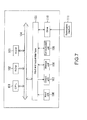
- FIG. 7 is a block diagram showing an example of the structure of hardware of a computer which executes the series of processes described above by a program.
- a CPU Central Processing Unit
- ROM Read Only Memory
- RAM Random Access Memory
- an input and output interface 105 is further connected.
- an input unit 106 an output unit 107 , a storage unit 108 , a communication unit 109 , and a drive 110 are connected.
- the input unit 106 may include a keyboard, a mouse, a microphone, or the like.
- the output unit 107 may include a display, a speaker, or the like.
- the storage unit 108 may include a hard disk, a nonvolatile memory, or the like.
- the communication unit 109 may include a network interface or the like.
- the drive 110 drives a removable medium 111 such as a magnetic disk, an optical disk, a magneto-optical disk, and a semiconductor memory.
- the CPU 101 loads a program stored in the storage unit 108 via the input and output interface 105 and the bus 104 into the RAM 103 , for example, and executes the program, thereby performing the series of processes described above.
- the program executed by the computer (CPU 101 ) can be recorded in the removable medium 111 and provided, for example as a package medium or the like. Further, the program can be provided via a wired or wireless transmission medium such as a local area network, the Internet, and digital satellite broadcasting.
- the program can be installed into the storage unit 108 via the input and output interface 105 by loading the removable medium 111 to the drive 110 . Further, the program can be received by the communication unit 109 via a wired or wireless transmission medium and installed into the storage unit 108 . In addition, the program can be installed in advance into the ROM 102 or the storage unit 108 .
- the processes of the program executed by the computer may be performed on a time-series basis in the order described in the specification, or may be performed in parallel or at necessary timings, for example, at a timing when being called.
- system refers to an entire apparatus constituted of a plurality of apparatuses.
- a reception apparatus including:
- a reception method for a reception apparatus including
- a program for causing a computer configured to control a reception apparatus including
Landscapes
- Engineering & Computer Science (AREA)
- Computer Networks & Wireless Communication (AREA)
- Signal Processing (AREA)
- Radio Transmission System (AREA)
- Mobile Radio Communication Systems (AREA)
Applications Claiming Priority (3)
| Application Number | Priority Date | Filing Date | Title |
|---|---|---|---|
| JP2013-212817 | 2013-10-10 | ||
| JP2013212817 | 2013-10-10 | ||
| PCT/JP2014/075798 WO2015053110A1 (fr) | 2013-10-10 | 2014-09-29 | Dispositif de réception, procédé de réception et programme |
Publications (2)
| Publication Number | Publication Date |
|---|---|
| US20160233943A1 US20160233943A1 (en) | 2016-08-11 |
| US9800315B2 true US9800315B2 (en) | 2017-10-24 |
Family
ID=52812929
Family Applications (1)
| Application Number | Title | Priority Date | Filing Date |
|---|---|---|---|
| US15/022,608 Active US9800315B2 (en) | 2013-10-10 | 2014-09-29 | Reception apparatus, reception method, and program |
Country Status (3)
| Country | Link |
|---|---|
| US (1) | US9800315B2 (fr) |
| JP (1) | JPWO2015053110A1 (fr) |
| WO (1) | WO2015053110A1 (fr) |
Citations (14)
| Publication number | Priority date | Publication date | Assignee | Title |
|---|---|---|---|---|
| JP2001203666A (ja) | 2000-01-24 | 2001-07-27 | Alps Electric Co Ltd | Ofdm受信装置 |
| US20030031234A1 (en) * | 2001-05-17 | 2003-02-13 | Smee John Edward | System and method for received signal prediction in wireless communications systems |
| US6532252B1 (en) * | 1998-06-13 | 2003-03-11 | Samsung Electronics, Co., Ltd. | Device and method for measuring non-orthogonal noise power for CDMA communication system |
| US20040102961A1 (en) * | 2002-11-22 | 2004-05-27 | Jensen James M. | Encoding multiple messages in audio data and detecting same |
| US20060293006A1 (en) * | 2004-07-28 | 2006-12-28 | Tomohiko Taniguchi | Diversity type receiver apparatus and receiving method |
| US20070142009A1 (en) * | 2005-12-01 | 2007-06-21 | Sirius Satellite Radio, Inc. | Systems and methods for antenna diversity combining for satellite radio signals |
| US20070248191A1 (en) * | 2006-04-25 | 2007-10-25 | Telefonaktiebolaget Lm Ericsson (Publ) | Baseband sample selection |
| US20100183100A1 (en) * | 2007-09-05 | 2010-07-22 | Kazuyuki Shimezawa | Receiver and reception method |
| US20100246637A1 (en) * | 2009-03-31 | 2010-09-30 | Samsung Electronics Co., Ltd. | Wireless communication device, wireless communication system, and method for detecting receive timing of direct wave |
| JP2010268224A (ja) | 2009-05-14 | 2010-11-25 | Nippon Telegr & Teleph Corp <Ntt> | ダイバーシチ通信装置 |
| US7965762B2 (en) * | 2000-10-11 | 2011-06-21 | Qualcomm Incorporated | Method and apparatus for measuring timing of signals received from multiple base stations in a CDMA communication system |
| US8290441B2 (en) * | 2004-12-20 | 2012-10-16 | Qualcomm Incorporated | Signaling bit detection with adaptive threshold |
| US20130115903A1 (en) * | 2011-11-07 | 2013-05-09 | Ibiquity Digital Corporation | Mrc antenna diversity for fm iboc digital signals |
| JP2013135270A (ja) | 2011-12-26 | 2013-07-08 | Sony Corp | 受信装置及び画像表示機器 |
Family Cites Families (4)
| Publication number | Priority date | Publication date | Assignee | Title |
|---|---|---|---|---|
| GB2259430B (en) * | 1991-09-07 | 1996-05-01 | Motorola Ltd | Radio receiver and transmitter providing diversity |
| JP2803614B2 (ja) * | 1995-12-22 | 1998-09-24 | 日本電気株式会社 | 移動中継装置 |
| DE19849318A1 (de) * | 1998-10-26 | 2000-04-27 | Rohde & Schwarz | Verfahren zum Verarbeiten von durch ein Mehrantennensystem gleichzeitig empfangenen OFDM-Signalen |
| CN102342056A (zh) * | 2009-03-05 | 2012-02-01 | 三菱电机株式会社 | 无线通信系统、发送装置以及接收装置 |
-
2014
- 2014-09-29 US US15/022,608 patent/US9800315B2/en active Active
- 2014-09-29 WO PCT/JP2014/075798 patent/WO2015053110A1/fr active Application Filing
- 2014-09-29 JP JP2015541519A patent/JPWO2015053110A1/ja active Pending
Patent Citations (14)
| Publication number | Priority date | Publication date | Assignee | Title |
|---|---|---|---|---|
| US6532252B1 (en) * | 1998-06-13 | 2003-03-11 | Samsung Electronics, Co., Ltd. | Device and method for measuring non-orthogonal noise power for CDMA communication system |
| JP2001203666A (ja) | 2000-01-24 | 2001-07-27 | Alps Electric Co Ltd | Ofdm受信装置 |
| US7965762B2 (en) * | 2000-10-11 | 2011-06-21 | Qualcomm Incorporated | Method and apparatus for measuring timing of signals received from multiple base stations in a CDMA communication system |
| US20030031234A1 (en) * | 2001-05-17 | 2003-02-13 | Smee John Edward | System and method for received signal prediction in wireless communications systems |
| US20040102961A1 (en) * | 2002-11-22 | 2004-05-27 | Jensen James M. | Encoding multiple messages in audio data and detecting same |
| US20060293006A1 (en) * | 2004-07-28 | 2006-12-28 | Tomohiko Taniguchi | Diversity type receiver apparatus and receiving method |
| US8290441B2 (en) * | 2004-12-20 | 2012-10-16 | Qualcomm Incorporated | Signaling bit detection with adaptive threshold |
| US20070142009A1 (en) * | 2005-12-01 | 2007-06-21 | Sirius Satellite Radio, Inc. | Systems and methods for antenna diversity combining for satellite radio signals |
| US20070248191A1 (en) * | 2006-04-25 | 2007-10-25 | Telefonaktiebolaget Lm Ericsson (Publ) | Baseband sample selection |
| US20100183100A1 (en) * | 2007-09-05 | 2010-07-22 | Kazuyuki Shimezawa | Receiver and reception method |
| US20100246637A1 (en) * | 2009-03-31 | 2010-09-30 | Samsung Electronics Co., Ltd. | Wireless communication device, wireless communication system, and method for detecting receive timing of direct wave |
| JP2010268224A (ja) | 2009-05-14 | 2010-11-25 | Nippon Telegr & Teleph Corp <Ntt> | ダイバーシチ通信装置 |
| US20130115903A1 (en) * | 2011-11-07 | 2013-05-09 | Ibiquity Digital Corporation | Mrc antenna diversity for fm iboc digital signals |
| JP2013135270A (ja) | 2011-12-26 | 2013-07-08 | Sony Corp | 受信装置及び画像表示機器 |
Also Published As
| Publication number | Publication date |
|---|---|
| US20160233943A1 (en) | 2016-08-11 |
| JPWO2015053110A1 (ja) | 2017-03-09 |
| WO2015053110A1 (fr) | 2015-04-16 |
Similar Documents
| Publication | Publication Date | Title |
|---|---|---|
| JP4145240B2 (ja) | ダイバーシチ受信方法および装置 | |
| US9800315B2 (en) | Reception apparatus, reception method, and program | |
| JP2004343656A (ja) | 受信装置 | |
| US8385486B2 (en) | Diversity receiving apparatus and diversity receiving method | |
| EP3142371B1 (fr) | Dispositif de réception et procédé de reproduction dans un dispositif de réception | |
| US20100027724A1 (en) | Receiver and receiving method | |
| US20100279642A1 (en) | Diversity receiver and diversity reception method | |
| US20110268172A1 (en) | Receiver apparatus and receiving method | |
| JP6403683B2 (ja) | 信号処理装置、信号処理方法、並びにプログラム | |
| WO2017073351A1 (fr) | Dispositif et procédé de traitement de signal, et programme | |
| JP2007180875A (ja) | 無線通信装置 | |
| JP5340236B2 (ja) | 復調装置 | |
| TWI463846B (zh) | Orthogonal Frequency Division Multiple Modulation (OFDM) Receiver | |
| JP2009130797A (ja) | ダイバシティ受信装置、放送受信方法およびデジタルテレビ受信装置 | |
| JP5720373B2 (ja) | 受信装置、受信方法、およびプログラム | |
| US9215013B2 (en) | Reception apparatus and electronic equipment | |
| JP4679392B2 (ja) | 受信装置 | |
| JP4738209B2 (ja) | 受信方法および装置 | |
| US20150092112A1 (en) | Reception device, reception method, and program | |
| JP5594205B2 (ja) | 無線装置および送信方法 | |
| US20160261329A1 (en) | Reception apparatus, reception method, and program | |
| JP4551432B2 (ja) | ダイバシティ受信装置およびダイバシティ受信方法 | |
| JP2010063027A (ja) | 受信装置および受信方法 | |
| JP2006067138A (ja) | ダイバーシチ中継装置 | |
| WO2013137222A1 (fr) | Dispositif de réception de communication par satellite et procédé de réception |
Legal Events
| Date | Code | Title | Description |
|---|---|---|---|
| AS | Assignment |
Owner name: SONY CORPORATION, JAPAN Free format text: ASSIGNMENT OF ASSIGNORS INTEREST;ASSIGNORS:YOKOKAWA, TAKASHI;OKADA, SATOSHI;MARUYAMA, HIROFUMI;REEL/FRAME:038131/0233 Effective date: 20160229 |
|
| STCF | Information on status: patent grant |
Free format text: PATENTED CASE |
|
| MAFP | Maintenance fee payment |
Free format text: PAYMENT OF MAINTENANCE FEE, 4TH YEAR, LARGE ENTITY (ORIGINAL EVENT CODE: M1551); ENTITY STATUS OF PATENT OWNER: LARGE ENTITY Year of fee payment: 4 |