US9744776B2 - Device for printing on multi-dimensional objects - Google Patents
Device for printing on multi-dimensional objects Download PDFInfo
- Publication number
- US9744776B2 US9744776B2 US15/196,124 US201615196124A US9744776B2 US 9744776 B2 US9744776 B2 US 9744776B2 US 201615196124 A US201615196124 A US 201615196124A US 9744776 B2 US9744776 B2 US 9744776B2
- Authority
- US
- United States
- Prior art keywords
- axis
- rotation
- printing device
- movement
- guide
- Prior art date
- Legal status (The legal status is an assumption and is not a legal conclusion. Google has not performed a legal analysis and makes no representation as to the accuracy of the status listed.)
- Active
Links
Images




Classifications
-
- B—PERFORMING OPERATIONS; TRANSPORTING
- B41—PRINTING; LINING MACHINES; TYPEWRITERS; STAMPS
- B41J—TYPEWRITERS; SELECTIVE PRINTING MECHANISMS, i.e. MECHANISMS PRINTING OTHERWISE THAN FROM A FORME; CORRECTION OF TYPOGRAPHICAL ERRORS
- B41J3/00—Typewriters or selective printing or marking mechanisms characterised by the purpose for which they are constructed
- B41J3/407—Typewriters or selective printing or marking mechanisms characterised by the purpose for which they are constructed for marking on special material
- B41J3/4073—Printing on three-dimensional objects not being in sheet or web form, e.g. spherical or cubic objects
-
- B—PERFORMING OPERATIONS; TRANSPORTING
- B05—SPRAYING OR ATOMISING IN GENERAL; APPLYING FLUENT MATERIALS TO SURFACES, IN GENERAL
- B05B—SPRAYING APPARATUS; ATOMISING APPARATUS; NOZZLES
- B05B13/00—Machines or plants for applying liquids or other fluent materials to surfaces of objects or other work by spraying, not covered by groups B05B1/00 - B05B11/00
- B05B13/02—Means for supporting work; Arrangement or mounting of spray heads; Adaptation or arrangement of means for feeding work
- B05B13/0221—Means for supporting work; Arrangement or mounting of spray heads; Adaptation or arrangement of means for feeding work characterised by the means for moving or conveying the objects or other work, e.g. conveyor belts
- B05B13/0235—Means for supporting work; Arrangement or mounting of spray heads; Adaptation or arrangement of means for feeding work characterised by the means for moving or conveying the objects or other work, e.g. conveyor belts the movement of the objects being a combination of rotation and linear displacement
-
- B—PERFORMING OPERATIONS; TRANSPORTING
- B05—SPRAYING OR ATOMISING IN GENERAL; APPLYING FLUENT MATERIALS TO SURFACES, IN GENERAL
- B05B—SPRAYING APPARATUS; ATOMISING APPARATUS; NOZZLES
- B05B13/00—Machines or plants for applying liquids or other fluent materials to surfaces of objects or other work by spraying, not covered by groups B05B1/00 - B05B11/00
- B05B13/02—Means for supporting work; Arrangement or mounting of spray heads; Adaptation or arrangement of means for feeding work
- B05B13/0285—Stands for supporting individual articles to be sprayed, e.g. doors, vehicle body parts
-
- B—PERFORMING OPERATIONS; TRANSPORTING
- B05—SPRAYING OR ATOMISING IN GENERAL; APPLYING FLUENT MATERIALS TO SURFACES, IN GENERAL
- B05B—SPRAYING APPARATUS; ATOMISING APPARATUS; NOZZLES
- B05B13/00—Machines or plants for applying liquids or other fluent materials to surfaces of objects or other work by spraying, not covered by groups B05B1/00 - B05B11/00
- B05B13/02—Means for supporting work; Arrangement or mounting of spray heads; Adaptation or arrangement of means for feeding work
- B05B13/04—Means for supporting work; Arrangement or mounting of spray heads; Adaptation or arrangement of means for feeding work the spray heads being moved during spraying operation
- B05B13/0431—Means for supporting work; Arrangement or mounting of spray heads; Adaptation or arrangement of means for feeding work the spray heads being moved during spraying operation with spray heads moved by robots or articulated arms, e.g. for applying liquid or other fluent material to three-dimensional [3D] surfaces
-
- B—PERFORMING OPERATIONS; TRANSPORTING
- B05—SPRAYING OR ATOMISING IN GENERAL; APPLYING FLUENT MATERIALS TO SURFACES, IN GENERAL
- B05B—SPRAYING APPARATUS; ATOMISING APPARATUS; NOZZLES
- B05B15/00—Details of spraying plant or spraying apparatus not otherwise provided for; Accessories
- B05B15/60—Arrangements for mounting, supporting or holding spraying apparatus
- B05B15/68—Arrangements for adjusting the position of spray heads
-
- B—PERFORMING OPERATIONS; TRANSPORTING
- B05—SPRAYING OR ATOMISING IN GENERAL; APPLYING FLUENT MATERIALS TO SURFACES, IN GENERAL
- B05B—SPRAYING APPARATUS; ATOMISING APPARATUS; NOZZLES
- B05B15/00—Details of spraying plant or spraying apparatus not otherwise provided for; Accessories
- B05B15/70—Arrangements for moving spray heads automatically to or from the working position
Definitions
- the invention relates to a device for printing on multidimensional objects, the device including an object carrier for holding and moving the object to be printed on, a tool carrier for receiving stationary processing tools, and a frame to which the tool carrier is fixed.
- a device for printing on multi-dimensional, namely three-dimensional spatial objects comprising an object carrier for holding and moving the object to be printed on, for instance a sphere, a cylinder, or a cuboid, a tool carrier for receiving multiple processing tools that are stationary during the processing operation, and a frame, in particular a gantry-shaped frame, on which the tool carrier is mounted, i.e. suspended.
- the object carrier has three guide tracks and three carriages movable thereon. The guide tracks are perpendicular or orthogonal to one another and each of them is oriented along a respective axis of movement.
- Each guide track is assigned a carriage for a translatory movement of the object relative to the stationary processing tools during the processing operation.
- the construction is such that a second guide track is disposed on the first carriage and a third guide track is disposed on the second carriage.
- An object carrier for gripping or clamping an object or holding it by suction may be disposed on the third carriage.
- Linear direct drives or spindle units may be provided as drives for the carriages along the guide tracks.
- a first guide track has two guide rails that are oriented to be parallel to one another and are in particular horizontal guide rails disposed in a horizontal plane.
- a respective guide rail of the first guide track may be disposed on a respective side wall in a position to be elevated relative to the foundation or a base plate of the printing device.
- the two side walls are interconnected and the two side walls form or represent the arms of a U profile.
- the U profile may extend beyond the frame.
- the U profile may be of unipartite construction or may preferably be composed of at least three elements or modules of identical construction. In this way, it is possible to process even especially long objects and to implement an automated supply and removal of the objects.
- the first guide track is embodied as a gantry carriage having a gantry drive, and two separate motors move the object along the first axis of movement due to an angle-synchronous actuation, allowing the object to move along the first axis of movement without jamming.
- the motors that are used for this purpose are in particular linear servomotors.
- At least one print head in particular an inkjet print head, is provided as a processing tool of the device.
- a pre-coat device, a plasma treatment device, a laser engraving device and/or a drier may be provided as further processing tools.
- a plurality of print heads is provided in a corresponding way.
- a pre-coat device, an inkjet print head, and a drier are provided at a minimum.
- the height of the tool carrier is adjustable and the tool carrier is movable along substantially vertical supports of the frame and lockable in position, allowing an adaptation to objects of varying sizes.
- the tool carrier has a recess for every processing tool to receive the processing tool.
- the recess is constructed to allow the respective processing tool to be inserted in two alternative positions that are offset by an angle of 90° relative to one another.
- a first position is advantageously oriented to be parallel to the first axis of movement and a second position is preferably oriented to be parallel to the second axis of movement.
- the orientation of the processing tools may be selected as a function of the object to be printed on and of the image to be printed.
- every recess is capable of locking a respective tool in both a lower operating position and in an upper standby position.
- the object carrier has a first axis of rotation for rotating the object, the first axis of rotation is oriented to be parallel to the first guide track and to the first axis of movement.
- the object carrier of the device additionally has a second axis of rotation for rotating the object, the second axis of rotation is oriented to be parallel to the first guide track and to the second axis of movement.
- the object carrier of the device additionally has a third axis of rotation for rotating the object, the third axis of rotation is oriented to be parallel to the third guide track and to the third axis of movement.
- the basic module which has three axes of translatory movement as described above, may be enhanced by one, two, or three additional axes of rotation as a function of the object to be printed on and of the image to be printed. Since the deviations of the individual servo-electric drives from their target movements add up to a total error of the desired movement between the object to be printed on and the processing tool, the provision of the lowest possible number of axes of rotation may keep the deviation on a low level.
- a modular construction of the printing device including one, two, or three axes of rotation allows the required number of axes of rotation to be easily selected as a function of the object to be printed on.
- FIG. 1A is a diagrammatic, perspective view of a printing device of the invention
- FIG. 1B is a perspective view of the device of FIG. 1A with an object to be printed on;
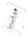
- FIG. 2 is an enlarged perspective view of a tool carrier of the device
- FIG. 3 is a perspective view of an elongated version of the device.
- FIGS. 4A-4E are perspective views of different embodiments of the device.
- FIG. 1A there is seen a modular printing device 100 of the invention.
- the printing device 100 has a tool carrier 11 held in vertical supports 9 of a frame 16 .
- the tool carrier 11 is vertically movable and lockable in the vertical supports 9 so that a height adjustment h of the tool carrier is possible.
- An object carrier 10 for moving a non-illustrated object to be printed on relative to the tool carrier 11 and its tools 12 , 13 , 14 is disposed below the tool carrier 11 .
- the object carrier 10 rests on or is fixed to a bottom or foundation or base plate 200 .
- the construction of the object carrier 10 is as follows:
- a gantry carriage 19 having a gantry drive is fixed to a U-shaped U profile element 18 having two side walls 17 .
- the gantry carriage 19 which provides a jam-free movement in an x direction, forms a first axis of movement 21 in the x direction.
- a second axis of movement 22 in the Y direction is disposed at a right angle relative thereto and a third axis of rotation 23 in a Z direction is disposed at a right angle relative thereto.
- the axes form the axes of movement of the object carrier 10 , allowing a non-illustrated object that is to be printed on and is held by the object carrier 10 to be moved along any desired path of movement b relative to the tool carrier 11 , which is stationary during the processing operation.
- the second axis of movement 22 is implemented by a second guide track including a guide carriage 32 .
- the second guide track is disposed on the gantry carriage 19 with the gantry drive as a first guide track with a guide carriage 31 .
- the first guide track has two, in particular horizontal, guide rails 20 oriented parallel to one another.
- the third axis of movement 23 is implemented by a third guide track with a guide carriage 33 .
- the third guide track in turn is disposed on the second guide track with the guide carriage 32 .
- the object carrier 10 thereof includes an object mount 10 . 1 including clamps for holding an object 1000 to be printed on, in this case a cuboid box.
- the object mount 10 . 1 is moved by using the guide tracks and guide carriages 31 , 32 , 33 .
- the object 1000 to be printed on may be moved relative to the stationary tool carrier 11 by using a movement of the object mount 10 . 1 .
- the object mount 10 . 1 in the illustration of FIG. 1B has been moved counter to the Y direction and in the x and z directions along the axes of movement 21 , 22 , 23 .
- first guide track with the guide carriage 31 is embodied as a gantry carriage 19 with a gantry drive
- the second guide track with the guide carriage 32 and the third guide track with the guide carriage 33 may have servo-electric drives, which may in particular be embodied as linear direct drives or spindle units.
- a self-locking spindle drive may represent an advantageous embodiment of the third guide track with the guide carriage 33 .
- the guide carriages 31 , 32 , 33 thus form a servo-electrically driven x, y, z linear system that allows an object mount 10 . 1 to be moved along almost any desired path of movement b.
- FIG. 2 is a more detailed view of the tool carrier 11 : the tool carrier 11 carries the processing tools for pre-treating, printing, and drying the object 1000 to be printed on as required for an inkjet printing operation.
- a pre-coat device 12 embodied as a plasma pre-treatment unit, four inkjet print heads 13 , and a drier 14 are provided.
- the tools 12 , 13 , 14 are received by respective recesses 15 of the tool carrier 11 . All of the processing tools 12 , 13 , 14 may be displaced relative to the tool carrier 11 between a lower operating position and an upper standby position and may be fixed in position.
- FIG. 1 is a more detailed view of the tool carrier 11 : the tool carrier 11 carries the processing tools for pre-treating, printing, and drying the object 1000 to be printed on as required for an inkjet printing operation.
- a pre-coat device 12 embodied as a plasma pre-treatment unit, four inkjet print heads 13 , and a drier 14 are provided.
- the pre-coat device 12 , the first print head 13 , and the third print head 13 are in standby positions whereas the second inkjet print head 13 , the fourth inkjet print head 13 , and the drier 14 are in lowered operating positions.
- the processing tools 12 , 13 , 14 may be displaced from an operating position to a standby position in a horizontal displacement and may be fixed therein.
- the recesses 15 for receiving the inkjet print heads 13 are embodied in such a way that a respective inkjet print head 13 may be mounted in two alternative positions that are rotated relative to one another through 90°.
- the inkjet print heads 13 have a first mounting position at 0° and a second mounting position in which the respective print head 13 has been rotated through 90°, allowing the orientation of the inkjet print heads 13 to be adapted to the object 1000 to be printed on.
- the possible displacement path of the first guide track with the guide carriage 31 in or against the x direction may be increased by extending the U profile 18 located underneath the tool carrier 11 with further U profile elements 18 as shown in FIG. 3 .
- the printing device 100 which was described and explained above based on the figures may be enhanced by adding axes of rotation 41 , 42 , 43 for rotating the objects 1000 to be printed on as a function of the structure of the objects 1000 to be printed on.
- the object carrier 10 of the printing device 100 has a rotation servo drive 51 for rotating an object 1000 to be printed on about a first axis of rotation 41 .
- the first axis of rotation 41 is oriented to be parallel to the first axis of movement 21 .
- the rotation servo drive 51 is preferably a direct servo drive, in particular a torque motor.
- a printing device 100 of this type constructed in accordance with FIG. 4A allows the third print head 13 to print ribbon-shaped printing strips as well as printing strips along the longitudinal axis of the object 1000 to be printed on.
- the rotation servo drive 51 generates the rotary printing motion, providing the progression of the image strips by a movement of the gantry carriage 19 .
- the gantry carriage 19 generates the printing motion, providing the progression of the image strips by a rotary movement of the rotation servo drive 51 .
- An object carrier 10 that has been enhanced by a first axis of rotation 41 in this way in particular allows rotary bodies having a straight circumferential line such as cylinders and cones to be printed on as objects 1000 to be printed on. However, it is also possible to print on surfaces that are irregularly curved in one plane.
- the object carrier 10 in addition to the first axis of rotation 41 , includes a second axis of rotation 42 oriented to be parallel to the second axis of movement 22 .
- a second rotation servo drive 52 is provided in order to rotate an object 1000 to be printed on about the axis of rotation 42 .
- Such a printing device 100 is capable of printing on objects 1000 to be printed on with surfaces that are curved in two planes. For reasons of clarity, the frame 16 of the device 100 is not shown in FIG. 4B .
- the axes of rotation 41 , 42 and the rotation drives 51 , 52 are supported on forks.
- An exterior fork which has end points that carry the second rotation servo drive 52 is fixed to the third guide track with the guide carriage 33 and receives an interior fork, at the center of which the first rotation servo drive 51 is disposed.
- a drive shaft of this first rotation servo drive 51 in turn carries the object 1000 to be printed on.
- the second rotation servo drive 52 may rotate the interior fork and the first rotation servo drive 51 may rotate the object 1000 to be printed on.
- the object 1000 to be printed on is advantageously mounted to the object carrier 10 in such a way that existing axes of symmetry of the object 1000 to be printed on coincide with the axes of rotation 41 , 42 . Thus the required movement of the object 1000 to be printed on during the printing operation may be minimized. It is further advantageous if an object 1000 to be printed on is mounted to the object carrier 10 in such a way that the center of gravity S of the object 1000 to be printed on is located at the intersection of the first axis of rotation 41 and the second axis of rotation 42 . In this case, the rotation servo drives 51 , 52 do not need to apply any holding torque.
- an enhanced printing device 100 including a third axis of rotation 43 as shown in FIG. 4C .
- the third axis of rotation 43 which is oriented to be parallel to the third axis of movement 23 , is provided in addition to the first axis of rotation 41 and the second axis of rotation 42 .
- a third rotation servo drive 53 for rotating the exterior fork is provided on the third guide track with the guide carriage 33 .
- An enhanced printing device 100 of this type may be used to freely position an object 1000 to be printed on, which may be aligned in any desired way with the aid of the three rotation servo drives 51 , 52 , 53 . This allows nearly any desired printing strips to be printed onto curved surfaces of objects 1000 to be printed on.
- FIG. 4D illustrates an alternative construction of the device 100 having a cylindrical object mount 10 . 1 .
- FIG. 4E illustrates an alternative configuration of the axes of rotation 41 , 42 , 43 .
- the drives 52 , 53 are fixed to L-shaped arms 8 rather than forks.
- the first rotation drive 51 for causing a rotation about the first axis of rotation 41 is fixed to the guide carriage 33 of the third guide track.
- the second rotation drive 52 for rotation about the second axis of rotation 42 is disposed on the first axis of rotation 41 at a right angle relative thereto via a right-angled, L-shaped arm 8 .
- the third rotation drive 53 for rotation about the third axis of rotation 43 is disposed on the second axis of rotation 42 via a further right-angled, L-shaped arm 8 .
- 4D is deemed to be that all three axes of rotation 41 , 42 , 43 are perpendicular to one another in respective pairs, even when the print head 13 or another processing tool 12 , 14 is located precisely opposite the mounting location of the mount 10 . 1 of the print object 1000 .
- the first and third axes of rotation are coaxial in this position (see FIG. 4D ), which corresponds to a singularity of the object carrier 10 .
- the device 100 is not capable of rotating the print object 1000 in any desired way.
Landscapes
- Engineering & Computer Science (AREA)
- Manufacturing & Machinery (AREA)
- Robotics (AREA)
- Ink Jet (AREA)
- Dot-Matrix Printers And Others (AREA)
- Character Spaces And Line Spaces In Printers (AREA)
Applications Claiming Priority (3)
| Application Number | Priority Date | Filing Date | Title |
|---|---|---|---|
| DE102015212757 | 2015-07-08 | ||
| DE102015212757 | 2015-07-08 | ||
| DE102015212757.5 | 2015-07-08 |
Publications (2)
| Publication Number | Publication Date |
|---|---|
| US20170008304A1 US20170008304A1 (en) | 2017-01-12 |
| US9744776B2 true US9744776B2 (en) | 2017-08-29 |
Family
ID=57583627
Family Applications (1)
| Application Number | Title | Priority Date | Filing Date |
|---|---|---|---|
| US15/196,124 Active US9744776B2 (en) | 2015-07-08 | 2016-06-29 | Device for printing on multi-dimensional objects |
Country Status (4)
| Country | Link |
|---|---|
| US (1) | US9744776B2 (ja) |
| JP (1) | JP6720002B2 (ja) |
| CN (1) | CN106335290B (ja) |
| DE (1) | DE102016209649A1 (ja) |
Cited By (3)
| Publication number | Priority date | Publication date | Assignee | Title |
|---|---|---|---|---|
| US20190105925A1 (en) * | 2017-10-09 | 2019-04-11 | Jean-Louis Dubuit | Machine for printing a plurality of objects |
| EP3991976A1 (en) * | 2020-10-27 | 2022-05-04 | Seiko Epson Corporation | Three-dimensional object printing apparatus and three-dimensional object printing method |
| US20230126054A1 (en) * | 2019-04-08 | 2023-04-27 | LSINC Corporation | Method for reconfiguring a media printer to optimize single media printing |
Families Citing this family (14)
| Publication number | Priority date | Publication date | Assignee | Title |
|---|---|---|---|---|
| US10005302B1 (en) * | 2017-04-03 | 2018-06-26 | Xerox Corporation | Object holder for a direct-to-object printer |
| US10005292B1 (en) * | 2017-04-03 | 2018-06-26 | Xerox Corporation | Object holder for a direct-to-object printer |
| KR102309412B1 (ko) * | 2017-04-19 | 2021-10-06 | 엘지전자 주식회사 | 차량에 구비된 차량 제어 장치 및 차량의 제어방법 |
| US10093112B1 (en) * | 2017-06-13 | 2018-10-09 | Xerox Corporation | Object holder for a direct-to-object printer |
| CN107199147B (zh) * | 2017-07-25 | 2023-04-25 | 四川科立达智能系统有限公司 | 一种智能喷涂门板的喷漆生产线 |
| JP7055032B2 (ja) * | 2018-02-16 | 2022-04-15 | 株式会社バンダイ | 保持装置、及び、制御装置 |
| FR3082780B1 (fr) * | 2018-06-21 | 2020-07-24 | Reydel Automotive Bv | Installation d'impression ou de revetement de surfaces de pieces tridimensionnelles |
| US11408166B2 (en) | 2018-12-21 | 2022-08-09 | Icon Technology, Inc. | Systems and methods for the construction of structures utilizing additive manufacturing techniques |
| DK3898144T3 (da) * | 2018-12-21 | 2024-11-11 | Icon Technologies Inc | Systemer til konstruktion af strukturer ved hjælp af supplerende fremstillingsteknikker |
| DE102019111034B4 (de) * | 2019-04-29 | 2022-11-10 | Illinois Tool Works Inc. | Digitaldruckanlage mit bogenförmiger werkstückbahn und verfahren zum bedrucken |
| JP7482421B2 (ja) * | 2019-12-04 | 2024-05-14 | パナソニックIpマネジメント株式会社 | 印刷装置 |
| CN112657715B (zh) * | 2020-12-14 | 2022-05-13 | 成都金斯特节能门窗有限公司 | 一种铝合金门窗加工设备及加工方法 |
| CN117619616B (zh) * | 2024-01-25 | 2024-03-22 | 蓬莱市阜康保温工程有限公司 | 一种隔热材料表面涂布装置 |
| CN121848821A (zh) * | 2024-10-14 | 2026-04-14 | 深圳市安克智造科技有限公司 | 打印设备和打印设备的控制方法 |
Citations (14)
| Publication number | Priority date | Publication date | Assignee | Title |
|---|---|---|---|---|
| DE142736C (ja) | ||||
| US5613403A (en) * | 1994-07-11 | 1997-03-25 | Nippon Thompson Co., Ltd. | Drive apparatus equipped with a ball screw and an XY drive apparatus containing said drive apparatus |
| US20010032387A1 (en) * | 2000-03-24 | 2001-10-25 | Olympus Optical Co., Ltd. | Electric wiring forming system |
| US20060290763A1 (en) * | 2005-06-23 | 2006-12-28 | Brother Kogyo Kabushiki Kaisha | Cloth holding frame |
| JP2007001164A (ja) | 2005-06-24 | 2007-01-11 | Mimaki Engineering Co Ltd | 立体メディアプリント用のインクジェットプリンタとそれを用いたプリント方法 |
| DE102009003443A1 (de) | 2009-02-05 | 2010-08-19 | Theodor Hymmen Holding Gmbh | Verfahren und Vorrichtung zum Bedrucken großformatiger Werkstücke |
| US7819055B2 (en) | 2006-11-06 | 2010-10-26 | Mimaki Engineering Co., Ltd. | Three-dimensional printer |
| US20110012952A1 (en) * | 2009-07-14 | 2011-01-20 | Hon Hai Precision Industry Co., Ltd. | Method for printing on a workpiece |
| US20110115849A1 (en) * | 2008-12-11 | 2011-05-19 | Mimaki Engineering Co., Ltd. | 3d inkjet printer |
| US20110148985A1 (en) * | 2009-12-23 | 2011-06-23 | Ulvac, Inc. | Parallel motion system for industrial printing |
| DE102010004496A1 (de) | 2010-01-12 | 2011-07-14 | Müller, Hermann, 88279 | Verfahren zum Betrieb einer Vorrichtung zum Beschichten und/oder Bedrucken eines Werkstückes |
| WO2013170888A1 (en) | 2012-05-15 | 2013-11-21 | Polytype S.A. | An inkjet printing machine and a corresponding printing method |
| US20130342592A1 (en) * | 2012-06-26 | 2013-12-26 | Apple Inc. | Inkjet printer for printing on a three-dimensional object and related apparatus and method |
| US20150273864A1 (en) * | 2014-03-27 | 2015-10-01 | Heidelberger Druckmaschinen Ag | Apparatus for printing a curved surface of an object |
Family Cites Families (11)
| Publication number | Priority date | Publication date | Assignee | Title |
|---|---|---|---|---|
| JPH10297035A (ja) * | 1997-04-24 | 1998-11-10 | Matsushita Electric Ind Co Ltd | インクジェット記録装置 |
| JP2001071285A (ja) * | 1999-09-01 | 2001-03-21 | Minolta Co Ltd | 作業ロボット |
| JP2001260329A (ja) * | 2000-03-22 | 2001-09-25 | Minolta Co Ltd | 立体物印刷装置および立体物印刷方法 |
| EP2229282A1 (en) * | 2007-12-31 | 2010-09-22 | Exatec, LLC. | Apparatus and method for printing three-dimensional articles |
| JP2011101838A (ja) * | 2009-11-10 | 2011-05-26 | Olympus Corp | パターン描画方法および装置 |
| CN101844314A (zh) * | 2010-05-12 | 2010-09-29 | 九川(浙江)科技股份有限公司 | 高速高精度伺服直线电机滑台 |
| CN101934944B (zh) * | 2010-09-03 | 2012-09-12 | 河北玉田兴业印刷机械有限公司 | 一种数字化高速纸堆送入装置 |
| KR101272299B1 (ko) * | 2011-08-25 | 2013-06-07 | (주)한 송 | Amoled 패널 제작용 분할 마스크 프레임 어셈블리 제조 장치 |
| SG11201401234UA (en) * | 2011-11-11 | 2014-09-26 | Nippon Sharyo Ltd | Stage device for laser processing machine |
| CN103358709A (zh) * | 2012-03-29 | 2013-10-23 | 宏塑工业股份有限公司 | 立体表面印刷设备 |
| CN203727002U (zh) * | 2014-01-06 | 2014-07-23 | 名丰科技股份有限公司 | 一种应用于曲面的3d喷印设备 |
-
2016
- 2016-06-02 DE DE102016209649.4A patent/DE102016209649A1/de active Pending
- 2016-06-29 US US15/196,124 patent/US9744776B2/en active Active
- 2016-07-08 CN CN201610536971.7A patent/CN106335290B/zh active Active
- 2016-07-08 JP JP2016135714A patent/JP6720002B2/ja active Active
Patent Citations (14)
| Publication number | Priority date | Publication date | Assignee | Title |
|---|---|---|---|---|
| DE142736C (ja) | ||||
| US5613403A (en) * | 1994-07-11 | 1997-03-25 | Nippon Thompson Co., Ltd. | Drive apparatus equipped with a ball screw and an XY drive apparatus containing said drive apparatus |
| US20010032387A1 (en) * | 2000-03-24 | 2001-10-25 | Olympus Optical Co., Ltd. | Electric wiring forming system |
| US20060290763A1 (en) * | 2005-06-23 | 2006-12-28 | Brother Kogyo Kabushiki Kaisha | Cloth holding frame |
| JP2007001164A (ja) | 2005-06-24 | 2007-01-11 | Mimaki Engineering Co Ltd | 立体メディアプリント用のインクジェットプリンタとそれを用いたプリント方法 |
| US7819055B2 (en) | 2006-11-06 | 2010-10-26 | Mimaki Engineering Co., Ltd. | Three-dimensional printer |
| US20110115849A1 (en) * | 2008-12-11 | 2011-05-19 | Mimaki Engineering Co., Ltd. | 3d inkjet printer |
| DE102009003443A1 (de) | 2009-02-05 | 2010-08-19 | Theodor Hymmen Holding Gmbh | Verfahren und Vorrichtung zum Bedrucken großformatiger Werkstücke |
| US20110012952A1 (en) * | 2009-07-14 | 2011-01-20 | Hon Hai Precision Industry Co., Ltd. | Method for printing on a workpiece |
| US20110148985A1 (en) * | 2009-12-23 | 2011-06-23 | Ulvac, Inc. | Parallel motion system for industrial printing |
| DE102010004496A1 (de) | 2010-01-12 | 2011-07-14 | Müller, Hermann, 88279 | Verfahren zum Betrieb einer Vorrichtung zum Beschichten und/oder Bedrucken eines Werkstückes |
| WO2013170888A1 (en) | 2012-05-15 | 2013-11-21 | Polytype S.A. | An inkjet printing machine and a corresponding printing method |
| US20130342592A1 (en) * | 2012-06-26 | 2013-12-26 | Apple Inc. | Inkjet printer for printing on a three-dimensional object and related apparatus and method |
| US20150273864A1 (en) * | 2014-03-27 | 2015-10-01 | Heidelberger Druckmaschinen Ag | Apparatus for printing a curved surface of an object |
Cited By (7)
| Publication number | Priority date | Publication date | Assignee | Title |
|---|---|---|---|---|
| US20190105925A1 (en) * | 2017-10-09 | 2019-04-11 | Jean-Louis Dubuit | Machine for printing a plurality of objects |
| US10981397B2 (en) * | 2017-10-09 | 2021-04-20 | Machines Dubuit | Machine for printing a plurality of objects |
| US20230126054A1 (en) * | 2019-04-08 | 2023-04-27 | LSINC Corporation | Method for reconfiguring a media printer to optimize single media printing |
| US11813844B2 (en) * | 2019-04-08 | 2023-11-14 | LSINC Corporation | Method for reconfiguring a media printer to optimize single media printing |
| EP3991976A1 (en) * | 2020-10-27 | 2022-05-04 | Seiko Epson Corporation | Three-dimensional object printing apparatus and three-dimensional object printing method |
| CN114474988A (zh) * | 2020-10-27 | 2022-05-13 | 精工爱普生株式会社 | 立体物印刷装置以及立体物印刷方法 |
| CN114474988B (zh) * | 2020-10-27 | 2025-11-21 | 精工爱普生株式会社 | 立体物印刷装置以及立体物印刷方法 |
Also Published As
| Publication number | Publication date |
|---|---|
| JP6720002B2 (ja) | 2020-07-08 |
| CN106335290B (zh) | 2020-08-04 |
| US20170008304A1 (en) | 2017-01-12 |
| JP2017024408A (ja) | 2017-02-02 |
| DE102016209649A1 (de) | 2017-01-12 |
| CN106335290A (zh) | 2017-01-18 |
Similar Documents
| Publication | Publication Date | Title |
|---|---|---|
| US20170008304A1 (en) | Device for printing on multi-dimensional objects | |
| JP5848387B2 (ja) | ワーク加工方法 | |
| TWI395632B (zh) | Deformable door type operating device | |
| CN106081619B (zh) | 一种精雕机全自动上下料设备 | |
| US9878409B2 (en) | Machine tool for machining | |
| CN205661225U (zh) | 一种精雕机全自动上下料设备 | |
| JP2010538845A (ja) | 製作品を精密加工する装置 | |
| CN108349077A (zh) | 机器人、此类型的机器人xy机台及线性传输系统 | |
| TWI540018B (zh) | 換刀系統及採用該換刀系統之機床 | |
| CN101573209A (zh) | 加工机械中的几何误差的补偿的方法和装置 | |
| WO2017182990A1 (en) | A robotic system for carrying out an operation | |
| CN104227702A (zh) | 双轨数控横梁式机械手 | |
| WO2017109980A1 (ja) | 工作機械システム | |
| CN110636920B (zh) | 具有两个工作主轴的工具机 | |
| CN111546083B (zh) | 一种工作台z轴运动的卧式五轴翻板加工中心 | |
| JPH0251702B2 (ja) | ||
| CN111546082B (zh) | 一种工作台上下垂直运动的卧式五轴翻板加工中心 | |
| CN212683148U (zh) | 一种工作台上下垂直运动的卧式五轴翻板加工中心 | |
| CN106914722B (zh) | 工件支承系统 | |
| JP5170225B2 (ja) | ワーク位置決め装置およびそれを用いた生産システム | |
| JP4899690B2 (ja) | 罫書装置 | |
| US20220234162A1 (en) | Honing apparatus | |
| CN100488715C (zh) | 复合工作机 | |
| CN211868089U (zh) | 一种五轴雕刻机 | |
| CN223947046U (zh) | 一种紧凑型双轴镭雕设备 |
Legal Events
| Date | Code | Title | Description |
|---|---|---|---|
| AS | Assignment |
Owner name: HEIDELBERGER DRUCKMASCHINEN AG, GERMANY Free format text: ASSIGNMENT OF ASSIGNORS INTEREST;ASSIGNORS:MOEHRINGER, MARKUS;NIGGEMANN, HENNING;REEL/FRAME:039080/0501 Effective date: 20160614 |
|
| STCF | Information on status: patent grant |
Free format text: PATENTED CASE |
|
| MAFP | Maintenance fee payment |
Free format text: PAYMENT OF MAINTENANCE FEE, 4TH YEAR, LARGE ENTITY (ORIGINAL EVENT CODE: M1551); ENTITY STATUS OF PATENT OWNER: LARGE ENTITY Year of fee payment: 4 |
|
| MAFP | Maintenance fee payment |
Free format text: PAYMENT OF MAINTENANCE FEE, 8TH YEAR, LARGE ENTITY (ORIGINAL EVENT CODE: M1552); ENTITY STATUS OF PATENT OWNER: LARGE ENTITY Year of fee payment: 8 |