US9728926B2 - Method and apparatus for radial ultrasonic welding interconnected coaxial connector - Google Patents
Method and apparatus for radial ultrasonic welding interconnected coaxial connector Download PDFInfo
- Publication number
- US9728926B2 US9728926B2 US13/170,958 US201113170958A US9728926B2 US 9728926 B2 US9728926 B2 US 9728926B2 US 201113170958 A US201113170958 A US 201113170958A US 9728926 B2 US9728926 B2 US 9728926B2
- Authority
- US
- United States
- Prior art keywords
- connector
- connector body
- outer conductor
- mating surface
- interconnection
- Prior art date
- Legal status (The legal status is an assumption and is not a legal conclusion. Google has not performed a legal analysis and makes no representation as to the accuracy of the status listed.)
- Active, expires
Links
Images


Classifications
-
- H—ELECTRICITY
- H01—ELECTRIC ELEMENTS
- H01R—ELECTRICALLY-CONDUCTIVE CONNECTIONS; STRUCTURAL ASSOCIATIONS OF A PLURALITY OF MUTUALLY-INSULATED ELECTRICAL CONNECTING ELEMENTS; COUPLING DEVICES; CURRENT COLLECTORS
- H01R43/00—Apparatus or processes specially adapted for manufacturing, assembling, maintaining, or repairing of line connectors or current collectors or for joining electric conductors
- H01R43/02—Apparatus or processes specially adapted for manufacturing, assembling, maintaining, or repairing of line connectors or current collectors or for joining electric conductors for soldered or welded connections
- H01R43/0207—Ultrasonic-, H.F.-, cold- or impact welding
-
- H—ELECTRICITY
- H01—ELECTRIC ELEMENTS
- H01R—ELECTRICALLY-CONDUCTIVE CONNECTIONS; STRUCTURAL ASSOCIATIONS OF A PLURALITY OF MUTUALLY-INSULATED ELECTRICAL CONNECTING ELEMENTS; COUPLING DEVICES; CURRENT COLLECTORS
- H01R13/00—Details of coupling devices of the kinds covered by groups H01R12/70 or H01R24/00 - H01R33/00
- H01R13/46—Bases; Cases
- H01R13/502—Bases; Cases composed of different pieces
- H01R13/504—Bases; Cases composed of different pieces different pieces being moulded, cemented, welded, e.g. ultrasonic, or swaged together
-
- H—ELECTRICITY
- H01—ELECTRIC ELEMENTS
- H01R—ELECTRICALLY-CONDUCTIVE CONNECTIONS; STRUCTURAL ASSOCIATIONS OF A PLURALITY OF MUTUALLY-INSULATED ELECTRICAL CONNECTING ELEMENTS; COUPLING DEVICES; CURRENT COLLECTORS
- H01R9/00—Structural associations of a plurality of mutually-insulated electrical connecting elements, e.g. terminal strips or terminal blocks; Terminals or binding posts mounted upon a base or in a case; Bases therefor
- H01R9/03—Connectors arranged to contact a plurality of the conductors of a multiconductor cable, e.g. tapping connections
- H01R9/05—Connectors arranged to contact a plurality of the conductors of a multiconductor cable, e.g. tapping connections for coaxial cables
-
- Y—GENERAL TAGGING OF NEW TECHNOLOGICAL DEVELOPMENTS; GENERAL TAGGING OF CROSS-SECTIONAL TECHNOLOGIES SPANNING OVER SEVERAL SECTIONS OF THE IPC; TECHNICAL SUBJECTS COVERED BY FORMER USPC CROSS-REFERENCE ART COLLECTIONS [XRACs] AND DIGESTS
- Y10—TECHNICAL SUBJECTS COVERED BY FORMER USPC
- Y10T—TECHNICAL SUBJECTS COVERED BY FORMER US CLASSIFICATION
- Y10T29/00—Metal working
- Y10T29/49—Method of mechanical manufacture
- Y10T29/49002—Electrical device making
- Y10T29/49117—Conductor or circuit manufacturing
- Y10T29/49123—Co-axial cable
-
- Y—GENERAL TAGGING OF NEW TECHNOLOGICAL DEVELOPMENTS; GENERAL TAGGING OF CROSS-SECTIONAL TECHNOLOGIES SPANNING OVER SEVERAL SECTIONS OF THE IPC; TECHNICAL SUBJECTS COVERED BY FORMER USPC CROSS-REFERENCE ART COLLECTIONS [XRACs] AND DIGESTS
- Y10—TECHNICAL SUBJECTS COVERED BY FORMER USPC
- Y10T—TECHNICAL SUBJECTS COVERED BY FORMER US CLASSIFICATION
- Y10T29/00—Metal working
- Y10T29/49—Method of mechanical manufacture
- Y10T29/49002—Electrical device making
- Y10T29/49117—Conductor or circuit manufacturing
- Y10T29/49204—Contact or terminal manufacturing
Definitions
- This invention relates to electrical cable connectors. More particularly, the invention relates to a coaxial connector and a method and apparatus for interconnection of such a coaxial cable connector with a coaxial cable, wherein a desired interconnection interface may be coupled via radial ultrasonic welding to a connector adapter previously coupled to a coaxial cable end.
- Coaxial cable connectors are used, for example, in communication systems requiring a high level of precision and reliability.
- Connectors configured for permanent interconnection via solder and/or adhesive interconnection are also well known in the art. Representative of this technology is commonly owned U.S. Pat. No. 5,802,710 issued Sep. 8, 1998 to Bufanda et al. However, solder and/or adhesive interconnections may be difficult to apply with high levels of quality control, resulting in interconnections that may be less than satisfactory, for example when exposed to vibration and/or corrosion over time.
- PIM Passive Intermodulation Distortion
- PIM is a form of electrical interference/signal transmission degradation that may occur with less than symmetrical interconnections and/or as electro-mechanical interconnections shift or degrade over time, for example due to mechanical stress, vibration, thermal cycling and/or material degradation.
- PIM is an important interconnection quality characteristic, as PIM from a single low quality interconnection may degrade the electrical performance of an entire RF system.
- the coaxial connector and/or coaxial cable may be mounted in a fixture which secures the connector and/or cable in a secure pre-determined orientation with respect to one another.
- multiple fixtures and/or mounting/remounting may be required to perform separate portions of the interconnection procedure, such as separately forming secure electro-mechanical interconnections with respect to each of the inner and outer conductors of the coaxial cable.
- each mounting/remounting procedure consumes additional time and/or may provide opportunities for the introduction of alignment errors. Further, repeated mounting/remounting may wear and/or damage mating surfaces of the assembly.
- Coaxial cables may be provided with connectors pre-attached. Such coaxial cables may be provided in custom or standardized lengths, for example for interconnections between equipment in close proximity to each other where the short cable portions are referred to as jumpers.
- To provide a coaxial cable with a high quality cable to connector interconnection may require either on-demand fabrication of the specified length of cable with the desired connection interface or stockpiling of an inventory of cables/jumpers in each length and interface that the consumer might be expected to request.
- On-demand fabrication and/or maintaining a large inventory of pre-assembled cable lengths, each with one of many possible connection interfaces, may increase delivery times and/or manufacturing/inventory costs.
- FIG. 1 is a schematic isometric view of an exemplary embodiment of a connector adapter coupled to a coaxial cable.
- FIG. 2 is a schematic isometric view of an interface end, with a Type-N Male connector interface.
- FIG. 3 is a schematic isometric view of an interface end, with a Type-N Female connector interface.
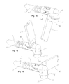
- FIG. 4 is a schematic isometric view of an interface end with a 7/16 DIN-Male connector interface.
- FIG. 5 is a schematic isometric view of the connector adapter of FIG. 1 with the interface end of FIG. 2 mounted thereon.
- FIG. 6 is a schematic isometric partial cut-away view of FIG. 5 .
- FIG. 7 is a schematic isometric view of the connector adapter of FIG. 1 with the interface end of FIG. 3 mounted thereon.
- FIG. 8 is a schematic isometric partial cut-away view of FIG. 7 .
- FIG. 9 is a schematic isometric view of the connector adapter of FIG. 1 with the interface end of FIG. 4 and a coupling nut mounted thereon.
- FIG. 10 is a schematic isometric partial cut-away view of FIG. 9 .
- FIG. 11 is a schematic isometric view of a fixture in a closed position for retaining the coaxial cable, connector adapter and interface end for interconnection via radial ultrasonic welding.
- FIG. 12 is a schematic isometric view of the connector adapter of FIG. 1 , immediately prior to simultaneous sonotrode engagement for radial ultrasonic welding of the interface end to the mating surface.
- FIG. 13 is a schematic isometric view of FIG. 12 , with the sonotrodes engaging the outer diameter of the interface end for radial ultrasonic welding.
- FIG. 14 is a schematic isometric view of a single sonotrode engaging an arc segment of the outer diameter of the interface end for radial ultrasonic welding.
- FIG. 15 is a schematic isometric view of another single sonotrode engaging another arc segment of the outer diameter of the interface end for radial ultrasonic welding.
- FIG. 16 is a schematic isometric view of another single sonotrode engaging a final arc segment of the outer diameter of the interface end for radial ultrasonic welding.
- FIG. 17 is an alternative embodiment of a connector adapter adapted for coupling with the outer conductor of the coaxial cable via laser welding.
- FIG. 18 is an alternative embodiment of a connector adapter adapted for coupling with the outer conductor of the coaxial cable via spin welding.
- Aluminum has been applied as a cost-effective alternative to copper for the conductors in coaxial cables.
- aluminum oxide surface coatings quickly form upon air-exposed aluminum surfaces. These aluminum oxide surface coatings may degrade traditional mechanical, solder and/or conductive adhesive interconnections.
- the inventor has recognized that increasing acceptance of coaxial cable with solid outer and/or inner conductors of aluminum and/or aluminum alloy enables connectors configured for interconnection via ultrasonic welding between the outer and inner conductors and a respective connector body and/or inner conductor cap inner contact which may each also be cost effectively provided, for example, formed from aluminum and/or aluminum alloy.
- the inventor has identified several difficulties arising from the interconnection of aluminum inner conductor coaxial cable configurations with prior coaxial cable connectors having inner contact configurations.
- Prior coaxial connector mechanical interconnection inner contact configurations are generally incompatible with aluminum inner conductors due to the creep characteristics of aluminum.
- galvanic corrosion between the aluminum inner conductor and a dissimilar metal of the inner contact such as bronze, brass or copper, may contribute to accelerated degradation of the electro-mechanical interconnection.
- An ultrasonic weld may be formed by applying ultrasonic vibrations under pressure in a join zone between two parts desired to be welded together, resulting in local heat sufficient to plasticize adjacent surfaces that are then held in contact with one another until the interflowed surfaces cool, completing the weld.
- An ultrasonic weld may be applied with high precision via a sonotrode and/or simultaneous sonotrode ends to a point and/or extended surface. Where a point ultrasonic weld is applied, successive overlapping point welds may be applied to generate a continuous ultrasonic weld.
- Ultrasonic vibrations may be applied, for example, in a linear direction and/or reciprocating along an arc segment, known as torsional vibration.
- these types of ultrasonic welding have previously typically utilized application of the sonotrode proximate the join zone from a direction in parallel with the longitudinal axis of the coaxial cable.
- the join zone location must be proximate the end of the assembly.
- interconnecting welds may be performed via ultrasonic vibrations applied to the cable and connector by a sonotrode approaching the join zone from a radial direction.
- a radial direction is a direction that is generally normal to the longitudinal axis of the coaxial cable. Therefore, radial ultrasonic welding is ultrasonic welding in which the weld is formed radially inward from an outer diameter of one of the elements being welded together, by a sonotrode applied to the outer diameter.
- an ultrasonic weld may be performed wherein the join zone is not proximate the end of the resulting assembly.
- the connector adapter comprises a unitary connector body 4 provided with a bore 6 dimensioned to receive the outer conductor 8 of a coaxial cable 9 therein.
- the connector adapter 1 may be interconnected with the outer conductor 8 according to conventional methods which preferably result in a molecular bond between the connector body 4 and the outer conductor 8 .
- the present embodiment demonstrates an ultrasonic welded interconnection between the connector body 4 and the outer conductor 8 .
- a flare seat 10 angled radially outward from the bore 6 toward a connector end 18 of the connector body 4 is open to the connector end of the connector adapter 1 , thereby providing a mating surface to which a leading end flare 14 of the outer conductor 8 may be ultrasonically welded by an outer conductor sonotrode of an ultrasonic welder inserted to contact the leading end flare 14 from the connector end 18 .
- connector end 18 and cable end 12 are applied herein as identifiers for respective ends of both the coaxial connector 2 and also of discrete elements of the coaxial connector 2 and thankotrodes described herein, to identify same and their respective interconnecting surfaces according to their alignment along a longitudinal axis of the connector between a connector end 18 and a cable end 12 .
- the leading end of the coaxial cable 9 may be prepared by cutting the coaxial cable 9 so that the inner conductor 24 extends from the outer conductor 8 . Also, dielectric material 26 between the inner conductor 24 and outer conductor 8 may be stripped back and a length of the outer jacket 28 removed to expose desired lengths of each.
- the cable end 12 of the coaxial cable 9 is inserted through the bore 6 and an annular flare operation is performed on a leading edge of the outer conductor 8 .
- the resulting leading end flare 14 may be angled to correspond to the angle of the flare seat 10 with respect to a longitudinal axis of the coaxial connector 2 .
- the resulting leading end flare 14 can be formed with a direct correspondence to the flare seat angle.
- the flare operation may be performed utilizing the leading edge of the outer conductor sonotrode, provided with a conical cylindrical inner lip with a connector end 18 diameter less than an inner diameter of the outer conductor 8 , for initially engaging and flaring the leading edge of the outer conductor 8 against the flare seat 10 .
- An overbody 30 may be applied to the connector body 4 as an overmolding of polymeric material.
- the overbody 30 increases cable to connector torsion and pull resistance.
- the overbody 30 may be provided dimensioned with an outer diameter cylindrical support surface 34 .
- Tool flats 39 (see FIG. 1 ) for retaining the resulting coaxial connector during interconnection with other cables and/or devices may be formed in the cylindrical support surface 34 by removing surface sections of the cylindrical support surface 34 .
- tool flats 39 may be formed on the interface end 2 (see FIG. 7 ).
- a coupling nut 36 may be present upon the interface end 2 retained at the connector end 18 by a flange 40 of the interface end 2 (see FIGS. 4, 9 and 10 ).
- the coupling nut 36 may be retained upon the cylindrical support surface 34 and/or support ridges of the overbody 30 by applying one or more retention spurs 41 (see FIG. 1 ) proximate the cable end of the cylindrical support surface 34 .
- the retention spurs 41 may be angled with increasing diameter from the cable end 12 to the connector end 18 , allowing the coupling nut 36 to be passed over them from the cable end 12 to the connector end 18 , but then retained upon the cylindrical support surface 34 by a stop face provided at the connector end 18 of the retention spurs 41 .
- the overbody 30 may be securely keyed to the connector body 4 via one or more interlock apertures 42 such as holes, longitudinal knurls, grooves, notches or the like provided in the outer diameter of the connector body 4 , as shown for example in FIG. 6 .
- interlock apertures 42 such as holes, longitudinal knurls, grooves, notches or the like provided in the outer diameter of the connector body 4 , as shown for example in FIG. 6 .
- the cable end of the overbody 30 may be dimensioned with an inner diameter friction surface 44 proximate that of the coaxial cable jacket 28 , enabling, for example, an interference fit and/or polymeric friction welding between the overbody 30 and the jacket 28 , by rotation of the connector body 4 with respect to the outer conductor 8 , thereby eliminating the need for environmental seals at the cable end 12 of the connector/cable interconnection.
- the overbody 30 may also have an extended cable portion proximate the cable end provided with a plurality of stress relief apertures 46 .
- the stress relief apertures 46 may be formed in a generally elliptical configuration with a major axis of the stress relief apertures 46 arranged normal to the longitudinal axis of the coaxial connector 2 .
- the stress relief apertures 46 enable a flexible characteristic of the cable end of the overbody 30 that increases towards the cable end of the overbody 30 .
- the overbody 30 supports the interconnection between the coaxial cable 9 and the coaxial connector 2 without introducing a rigid end edge along which a connected coaxial cable 2 subjected to bending forces may otherwise buckle, which may increase both the overall strength and the flexibility characteristics of the interconnection.
- overbody 30 is interconnected with the jacket 28 via friction welding, friction between the friction surface 44 and the outer diameter of the jacket 28 heats the respective surfaces to a point where they begin to soften and intermingle, sealing them against one another.
- the jacket 28 and/or the inner diameter of the overbody 30 may be provided as a series of spaced apart annular peaks of a contour pattern such as a corrugation, or a stepped surface, to provide enhanced friction, allow voids for excess friction weld material flow, and/or add key locking for additional strength.
- the overbody 30 may be sealed against the outer jacket 28 with an adhesive/sealant or may be overmolded upon the connector body 4 after interconnection with the outer conductor 8 , the heat of the injected polymeric material bonding the overbody 30 with and/or sealing against the jacket 28 .
- the prepared end of the coaxial cable 9 is inserted through the coupling nut 36 , if present, (the coupling nut 36 is advanced along the coaxial cable 9 out of the way until interconnection is completed) and connector body bore 6 so that the outer conductor 8 extends past the flare seat 10 a desired distance.
- the connector body 4 and/or cable end of the overbody 30 may be coated with an adhesive prior to insertion, and/or a spin welding operation may be performed to fuse the overbody 30 and/or cable end of the connector body 4 with the jacket 28 .
- the connector body 4 and coaxial cable 9 are then retained in a fixture 37 , rigidly securing these elements for the flaring and electrical interconnection friction welding via ultrasonic welding steps.
- the fixture 37 may be any manner of releasable retention mechanism into which the coaxial cable and/or coaxial connector 2 may be easily inserted and then released, for example as demonstrated in FIG. 11 .
- the flaring operation may be performed with a separate flare tool or via advancing the outer conductor sonotrode to contact the leading edge of the head of the outer conductor 8 , resulting in flaring the leading edge of the outer conductor 8 against the flare seat 10 .
- the outer conductor sonotrode may be advanced (if not already so seated after flaring is completed) upon the leading end flare 14 and ultrasonic welding initiated.
- Ultrasonic welding may be performed, for example, utilizing linear and/or torsional vibration.
- a linear vibration is applied to a cable end side of the leading end flare 14 , while the coaxial connector 2 and flare seat 10 therewithin are held static within the fixture 37 .
- the linear vibration generates a friction heat which plasticizes the contact surfaces between the leading end flare 14 and the flare seat 10 .
- a suitable frequency and linear displacement such as between 20 and 40 KHz and 20-35 microns, selected for example with respect to a material characteristic, diameter and/or sidewall thickness of the outer conductor 8 , may be applied.
- a desired interface end 2 may be applied to the connector adapter 1 immediately upon completion of the connector adapter and coaxial cable interconnection, or at a later time according to a just-in-time custom order fulfillment procedure.
- an inner conductor cap 20 for example formed from a metal such as brass or other desired metal, may be applied to the end of the inner conductor 24 , also by friction welding such as ultrasonic welding.
- the inner conductor cap 20 may be provided with an inner conductor socket at the cable end 12 and a desired inner conductor interface 22 at the connector end 4 .
- the inner conductor socket may be dimensioned to mate with a prepared end 23 of an inner conductor 24 of a coaxial cable 9 .
- the end of the inner conductor 24 is ground to provide a pin corresponding to the selected socket geometry of the inner conductor cap 20 .
- the socket geometry of the inner conductor cap 20 and/or the end of the inner conductor 24 may be formed to provide a material gap 25 .
- a rotation key 27 may be provided upon the inner conductor cap 20 , the rotation key 27 dimensioned to mate with an inner sonotrode tool for rotating and/or torsionally reciprocating the inner conductor cap 20 , for interconnection via ultrasonic friction welding.
- a torsional vibration is applied to the interconnection via the inner conductor sonotrode coupled to the inner conductor cap 20 by the rotation key 27 , while the coaxial cable 9 with inner conductor 24 therewithin are held static within the fixture 37 .
- the torsional vibration generates a friction heat which plasticizes the contact surfaces between the prepared end 23 and the inner conductor cap 20 .
- a suitable frequency and torsional vibration displacement for example between 20 and 40 KHz and 20-35 microns, may be applied, also selected with respect to material characteristics and/or dimensions of the mating surfaces.
- the corresponding interface end 2 may be seated upon the mating surface 49 and ultrasonic welded.
- the mating surface 49 has a diameter which decreases towards the connector end 18 , such as a conical or a curved surface, enabling a self-aligning fit that may be progressively tightened by application of axial compression.
- the selected interface end 2 seats upon a mating surface 49 provided on the connector end 18 of the connector adapter 1 .
- the interface end 2 may be seated upon the mating surface 49 , for example in a self aligning interference fit, until the connector end of the connector adapter 1 abuts a stop shoulder 32 of the interface end bore and/or cable end of the connector adapter 1 abuts the connector end of the overbody 30 (See FIG. 5 ).
- An annular seal groove 52 may be provided in the mating surface for a gasket 54 such as a polymer o-ring for environmentally sealing the interconnection of the connector adapter 1 and the selected interface end 2 .
- radial ultrasonic welding is applied.
- a plurality of sonotrodes 16 may be extended radially inward toward the outer diameter of the cable end of the interface end 2 to apply the selected ultrasonic vibration to the joint area.
- a single sonotrode 16 may be applied moving to address each of several designated arc portions of the outer diameter of the joint area or upon overlapping arc portions of the outer diameter of the joint area in sequential welding steps or in a continuous circumferential path along the join zone. Where the seal groove 52 and gasket 54 are present, even if a contiguous circumferential weld is not achieved, the interconnection remains environmentally sealed.
- the interface end 2 may also be in the form of a right angle connector configuration, for example as shown in FIGS. 4, 9 and 10 .
- the extent of the inner conductor cap 20 extending normal to the inner conductor 24 may be utilized as the rotation key 27 . Additional support of the extended inner conductor cap 20 may be provided by application of an inner conductor cap insulator 56 , after the interface end 2 is seated upon the connector adapter 1 .
- the inner conductor cap insulator 56 may snap-fit into place and/or be retained by a stamping operation upon a deformation groove 58 provided in the connection interface 31 of the connector end 2 .
- the interconnection between the connector adapter 1 and the outer conductor 8 has been demonstrated as performed by ultrasonic welding, one skilled in the art will appreciate that in alternative embodiments this interconnection may be achieved via other methods. Preferably, the interconnection results in a molecular bond interconnection. A molecular bond interconnection may also be achieved for example via laser welding or spin welding.
- the flare seat is omitted and a laser weld is applied to the joint between the outer conductor 8 and the connector body 4 at the connector end of the bore 6 .
- an inward projecting shoulder 60 angled toward a cable end 12 of the connector body 4 forms an annular friction groove 62 open to the cable end 12 .
- the friction groove 62 is dimensioned to receive a leading edge of the outer conductor 8 therein, a thickness of the outer conductor 8 preventing the outer conductor 8 from initially bottoming in the friction groove 62 , forming an annular material chamber 64 between the leading edge of the outer conductor 8 and the bottom of the friction groove 62 , when the outer conductor 8 is initially seated within the friction groove 14 .
- Friction generated by rotation of the connector adapter 1 with respect to the outer conductor 8 generates sufficient heat to soften the leading edge and/or localized adjacent portions of the outer conductor 8 and connector body 4 , forging them together as the sacrificial portion of the outer conductor 8 forms a plastic weld bead that flows into the material chamber 64 to fuse the outer conductor 8 and connector body 4 together.
- connector adapter 1 and interconnection method disclosed has significant material cost efficiencies and provides a permanently sealed interconnection with reduced size and/or weight requirements.
- a circumferential molecular bond is established at the connector body 4 to outer conductor 8 electro-mechanical interconnection, PIM resulting from such interconnection may be significantly reduced and/or entirely eliminated.
- the coaxial cable 9 , connector adapter 1 and interface end 2 provide a high quality assembly with advantageous characteristics.
- the assembly may be quickly and cost efficiently configured according to a specific customer connection interface 31 requirements, without maintaining an extensive finished jumper inventory.
- connector adapter 1 By pre-applying connector adapter 1 to the coaxial cables, potential for damage to the cable ends during storage and/or transport may be reduced and quality control of the interconnection may be improved. Further, high quality right angle connector interfaces are enabled, provided with reduced potential for PIM, again due to the molecular bond interconnection.
- connection interface 32 stop shoulder 34 support surface 36 coupling nut 37 fixture 38 alignment cylinder 39 tool flat 40 flange 41 retention spur 42 interlock aperture 44 friction surface 46 stress relief aperture 49 mating surface 52 seal groove 54 gasket 56 insulator 58 deformation groove 60 inward projecting shoulder 62 friction groove 64 material chamber
Priority Applications (21)
| Application Number | Priority Date | Filing Date | Title |
|---|---|---|---|
| US13/170,958 US9728926B2 (en) | 2010-11-22 | 2011-06-28 | Method and apparatus for radial ultrasonic welding interconnected coaxial connector |
| PCT/US2011/046054 WO2012071085A1 (en) | 2010-11-22 | 2011-07-30 | Method and apparatus for radial ultrasonic welding interconnected coaxial connector |
| EP11843398.6A EP2643899B1 (en) | 2010-11-22 | 2011-07-30 | Method and apparatus for radial ultrasonic welding interconnected coaxial connector |
| CN201180054850.4A CN103222126B (zh) | 2010-11-22 | 2011-07-30 | 用于径向超声焊接的互连同轴连接器的方法和装置 |
| US13/240,344 US8887388B2 (en) | 2010-11-22 | 2011-09-22 | Method for interconnecting a coaxial connector with a solid outer conductor coaxial cable |
| EP11843118.8A EP2643897B1 (en) | 2010-11-22 | 2011-09-23 | Connector and coaxial cable with molecular bond interconnection |
| PCT/US2011/052907 WO2012071106A1 (en) | 2010-11-22 | 2011-09-23 | Connector and coaxial cable with molecular bond interconnection |
| CN201180054849.1A CN103210552B (zh) | 2010-11-22 | 2011-09-23 | 具有分子键合互连的连接器和同轴线缆 |
| US13/294,586 US8550843B2 (en) | 2010-11-22 | 2011-11-11 | Tabbed connector interface |
| CN2011800548519A CN103222119A (zh) | 2010-11-22 | 2011-11-17 | 有凸片的连接器接口 |
| PCT/US2011/061101 WO2012071234A2 (en) | 2010-11-22 | 2011-11-17 | Tabbed connector interface |
| EP11842682.4A EP2643895A4 (en) | 2010-11-22 | 2011-11-17 | FOOT CONNECTOR INTERFACE |
| US13/673,373 US8622762B2 (en) | 2010-11-22 | 2012-11-09 | Blind mate capacitively coupled connector |
| US13/673,084 US8622768B2 (en) | 2010-11-22 | 2012-11-09 | Connector with capacitively coupled connector interface |
| US13/672,965 US8876549B2 (en) | 2010-11-22 | 2012-11-09 | Capacitively coupled flat conductor connector |
| US14/520,749 US9583847B2 (en) | 2010-11-22 | 2014-10-22 | Coaxial connector and coaxial cable interconnected via molecular bond |
| US15/443,690 US20170170612A1 (en) | 2010-11-22 | 2017-02-27 | Connector and coaxial cable with molecular bond interconnection |
| US15/670,581 US10355436B2 (en) | 2010-11-22 | 2017-08-07 | Method and apparatus for radial ultrasonic welding interconnected coaxial connector |
| US17/158,352 US11437767B2 (en) | 2010-11-22 | 2021-01-26 | Connector and coaxial cable with molecular bond interconnection |
| US17/158,286 US11437766B2 (en) | 2010-11-22 | 2021-01-26 | Connector and coaxial cable with molecular bond interconnection |
| US17/823,202 US11735874B2 (en) | 2010-11-22 | 2022-08-30 | Connector and coaxial cable with molecular bond interconnection |
Applications Claiming Priority (5)
| Application Number | Priority Date | Filing Date | Title |
|---|---|---|---|
| US12/951,558 US8826525B2 (en) | 2010-11-22 | 2010-11-22 | Laser weld coaxial connector and interconnection method |
| US12/974,765 US8563861B2 (en) | 2010-11-22 | 2010-12-21 | Friction weld inner conductor cap and interconnection method |
| US12/980,013 US8453320B2 (en) | 2010-11-22 | 2010-12-28 | Method of interconnecting a coaxial connector to a coaxial cable via ultrasonic welding |
| US13/161,326 US8365404B2 (en) | 2010-11-22 | 2011-06-15 | Method for ultrasonic welding a coaxial cable to a coaxial connector |
| US13/170,958 US9728926B2 (en) | 2010-11-22 | 2011-06-28 | Method and apparatus for radial ultrasonic welding interconnected coaxial connector |
Related Parent Applications (2)
| Application Number | Title | Priority Date | Filing Date |
|---|---|---|---|
| US12/974,765 Continuation-In-Part US8563861B2 (en) | 2010-11-22 | 2010-12-21 | Friction weld inner conductor cap and interconnection method |
| US13/161,326 Continuation-In-Part US8365404B2 (en) | 2010-11-22 | 2011-06-15 | Method for ultrasonic welding a coaxial cable to a coaxial connector |
Related Child Applications (4)
| Application Number | Title | Priority Date | Filing Date |
|---|---|---|---|
| US13/161,326 Continuation-In-Part US8365404B2 (en) | 2010-11-22 | 2011-06-15 | Method for ultrasonic welding a coaxial cable to a coaxial connector |
| US13/240,344 Continuation-In-Part US8887388B2 (en) | 2010-11-22 | 2011-09-22 | Method for interconnecting a coaxial connector with a solid outer conductor coaxial cable |
| US13/294,586 Continuation-In-Part US8550843B2 (en) | 2010-11-22 | 2011-11-11 | Tabbed connector interface |
| US15/670,581 Continuation US10355436B2 (en) | 2010-11-22 | 2017-08-07 | Method and apparatus for radial ultrasonic welding interconnected coaxial connector |
Publications (2)
| Publication Number | Publication Date |
|---|---|
| US20120129384A1 US20120129384A1 (en) | 2012-05-24 |
| US9728926B2 true US9728926B2 (en) | 2017-08-08 |
Family
ID=46064760
Family Applications (2)
| Application Number | Title | Priority Date | Filing Date |
|---|---|---|---|
| US13/170,958 Active 2034-01-15 US9728926B2 (en) | 2010-11-22 | 2011-06-28 | Method and apparatus for radial ultrasonic welding interconnected coaxial connector |
| US15/670,581 Active US10355436B2 (en) | 2010-11-22 | 2017-08-07 | Method and apparatus for radial ultrasonic welding interconnected coaxial connector |
Family Applications After (1)
| Application Number | Title | Priority Date | Filing Date |
|---|---|---|---|
| US15/670,581 Active US10355436B2 (en) | 2010-11-22 | 2017-08-07 | Method and apparatus for radial ultrasonic welding interconnected coaxial connector |
Country Status (4)
| Country | Link |
|---|---|
| US (2) | US9728926B2 (zh) |
| EP (1) | EP2643899B1 (zh) |
| CN (1) | CN103222126B (zh) |
| WO (1) | WO2012071085A1 (zh) |
Families Citing this family (20)
| Publication number | Priority date | Publication date | Assignee | Title |
|---|---|---|---|---|
| US8302296B2 (en) | 2010-11-22 | 2012-11-06 | Andrew, Llc | Friction weld coaxial connector and interconnection method |
| US8622762B2 (en) * | 2010-11-22 | 2014-01-07 | Andrew Llc | Blind mate capacitively coupled connector |
| US8887388B2 (en) * | 2010-11-22 | 2014-11-18 | Andrew Llc | Method for interconnecting a coaxial connector with a solid outer conductor coaxial cable |
| US8365404B2 (en) | 2010-11-22 | 2013-02-05 | Andrew Llc | Method for ultrasonic welding a coaxial cable to a coaxial connector |
| US8826525B2 (en) * | 2010-11-22 | 2014-09-09 | Andrew Llc | Laser weld coaxial connector and interconnection method |
| US8479383B2 (en) | 2010-11-22 | 2013-07-09 | Andrew Llc | Friction weld coaxial connector and interconnection method |
| US9728926B2 (en) | 2010-11-22 | 2017-08-08 | Commscope Technologies Llc | Method and apparatus for radial ultrasonic welding interconnected coaxial connector |
| US8657620B2 (en) * | 2011-12-22 | 2014-02-25 | General Electric Company | Connector assembly having a cable clamp coupled to a collet including an arbor |
| US8801460B2 (en) * | 2012-11-09 | 2014-08-12 | Andrew Llc | RF shielded capacitively coupled connector |
| JP2015220187A (ja) * | 2014-05-21 | 2015-12-07 | 第一電子工業株式会社 | 同軸コネクタ |
| US9614302B2 (en) * | 2015-02-04 | 2017-04-04 | Commscope Technologies Llc | Right angle coaxial cable and connector assembly |
| JP2017220303A (ja) * | 2016-06-03 | 2017-12-14 | ソニー株式会社 | コネクタ装置及び同軸コネクタ |
| JP6443637B2 (ja) * | 2016-10-06 | 2018-12-26 | 第一精工株式会社 | 同軸ケーブルコネクタ及び同軸ケーブル接続方法 |
| USD823100S1 (en) * | 2017-07-19 | 2018-07-17 | Dazadi, Inc. | Tube connector |
| US10797412B2 (en) | 2017-11-21 | 2020-10-06 | Amphenol Corporation | High frequency electrical connector |
| US10886685B2 (en) * | 2019-03-08 | 2021-01-05 | Onanon, Inc. | Preformed solder-in-pin system |
| US11509075B2 (en) * | 2019-11-12 | 2022-11-22 | Amphenol Corporation | High frequency electrical connector |
| US11489300B2 (en) | 2020-02-20 | 2022-11-01 | Amphenol Corporation | Coupling mechanism and connector with the same |
| USD993182S1 (en) | 2020-02-20 | 2023-07-25 | Amphenol Corporation | Electrical connector |
| US11715919B2 (en) | 2020-02-20 | 2023-08-01 | Amphenol Corporation | Coupling mechanism and connector with the same |
Citations (59)
| Publication number | Priority date | Publication date | Assignee | Title |
|---|---|---|---|---|
| US3264602A (en) | 1964-03-13 | 1966-08-02 | Automatic Metal Products Corp | Electrical connectors for coaxial cables |
| US3453376A (en) | 1966-07-05 | 1969-07-01 | Amp Inc | Center contact structure for coaxial cable conductors |
| US3656092A (en) | 1970-08-07 | 1972-04-11 | Amp Inc | Terminal device for welded termination of electrical leads |
| US3665367A (en) | 1969-08-20 | 1972-05-23 | Martin Marietta Corp | Side hole terminal |
| US3949466A (en) | 1974-05-28 | 1976-04-13 | Arthur D. Little Inc. | Process for forming an aluminum electrical conducting wire junction end piece |
| US4176909A (en) * | 1977-01-18 | 1979-12-04 | Souriau Et Cie | Processes for preparing a connector end on a fiber bundle optical cable and cables thus obtained |
| US4521642A (en) | 1980-06-05 | 1985-06-04 | Les Cables De Lyon | Sealed connection connecting an undersea coaxial cable to a repeater and a method of making same |
| US4746305A (en) | 1986-09-17 | 1988-05-24 | Taisho Electric Industrial Co. Ltd. | High frequency coaxial connector |
| US4867370A (en) | 1987-04-09 | 1989-09-19 | American Technology, Inc. | Apparatus and method for ultrasonic welding of wires |
| US4891015A (en) | 1989-01-09 | 1990-01-02 | Wiltron Company | Universal connector with interchangeable male and female sleeves for use in network analyzers and microwave devices |
| US5046952A (en) | 1990-06-08 | 1991-09-10 | Amp Incorporated | Right angle connector for mounting to printed circuit board |
| US5076657A (en) | 1989-09-25 | 1991-12-31 | Hitachi Cable Ltd. | Connection structure of optical fibers sealed in metal pipes and method for connecting optical fibers sealed in metal pipes |
| US5154636A (en) | 1991-01-15 | 1992-10-13 | Andrew Corporation | Self-flaring connector for coaxial cable having a helically corrugated outer conductor |
| US5186644A (en) | 1991-03-13 | 1993-02-16 | Molex Incorporated | Electrical connector system |
| US5203079A (en) | 1991-11-13 | 1993-04-20 | Molex Incorporated | Method of terminating miniature coaxial electrical connector |
| DE4210547C1 (zh) | 1992-03-31 | 1993-06-03 | Heinrich Dr. Moresnet-Chapelle Be Hampel | |
| US5284449A (en) | 1993-05-13 | 1994-02-08 | Amphenol Corporation | Connector for a conduit with an annularly corrugated outer casing |
| US5299939A (en) | 1992-03-05 | 1994-04-05 | International Business Machines Corporation | Spring array connector |
| US5354217A (en) | 1993-06-10 | 1994-10-11 | Andrew Corporation | Lightweight connector for a coaxial cable |
| US5561900A (en) | 1993-05-14 | 1996-10-08 | The Whitaker Corporation | Method of attaching coaxial connector to coaxial cable |
| US5791919A (en) | 1996-04-30 | 1998-08-11 | Constant Velocity Transmission Lines, Inc. | Universal connector |
| US5796315A (en) | 1996-07-01 | 1998-08-18 | Tracor Aerospace Electronic Systems, Inc. | Radio frequency connector with integral dielectric coating for direct current blockage |
| US5823824A (en) | 1994-03-07 | 1998-10-20 | Yazaki Corporation | Sealed connector |
| US6007378A (en) | 1997-05-02 | 1999-12-28 | Qualcomm Incorporated | Locking boot system |
| US6032835A (en) | 1993-01-19 | 2000-03-07 | Glaxo Group Ltd. | Aerosol dispenser and method |
| US6093043A (en) | 1997-04-01 | 2000-07-25 | Itt Manufacturing Enterprises, Inc. | Connector locking mechanism |
| US6174200B1 (en) | 1998-11-13 | 2001-01-16 | Framatome Connectors International | Electric connector |
| US6176716B1 (en) | 1997-07-11 | 2001-01-23 | Monster Cable Products, Inc. | Interchangeable electrical connector |
| US6439924B1 (en) | 2001-10-11 | 2002-08-27 | Corning Gilbert Inc. | Solder-on connector for coaxial cable |
| JP2002310117A (ja) | 2001-04-17 | 2002-10-23 | Cable Technica Co Ltd | ケーブルの接合構造及び接合方法 |
| US6588646B2 (en) | 2001-11-24 | 2003-07-08 | Delphi Technologies, Inc. | Ultrasonic welding of wires through the insulation jacket thereof |
| US6607399B2 (en) | 2001-05-29 | 2003-08-19 | Yazaki Corporation | Coax connector for preventing thermal degradation of transmission characteristics |
| US6752668B2 (en) | 2002-08-14 | 2004-06-22 | Konnektech, Ltd. | Electrical connector |
| US6776620B2 (en) | 2001-01-19 | 2004-08-17 | Molex Incorporated | Right-angle coaxial connector |
| US6786767B1 (en) | 2000-06-27 | 2004-09-07 | Astrolab, Inc. | Connector for coaxial cable |
| US6793095B1 (en) | 1998-02-04 | 2004-09-21 | Essef Corporation | Blow-molded pressure tank with spin-welded connector |
| US6814625B2 (en) | 2001-04-10 | 2004-11-09 | Cinch Connectors, Inc. | Electrical connector |
| US6837751B2 (en) | 2002-07-25 | 2005-01-04 | Delphi Technologies, Inc. | Electrical connector incorporating terminals having ultrasonically welded wires |
| CN1623254A (zh) | 2002-01-23 | 2005-06-01 | Vega格里沙贝两合公司 | 具有组合的电隔离的同轴线插塞连接装置 |
| US6932644B1 (en) | 2004-03-31 | 2005-08-23 | Sri Hermetics Inc. | Dissimilar metal hermetic connector |
| US20050285702A1 (en) | 2004-06-25 | 2005-12-29 | Andrew Corporation | Universal waveguide interface adaptor |
| US7044785B2 (en) | 2004-01-16 | 2006-05-16 | Andrew Corporation | Connector and coaxial cable with outer conductor cylindrical section axial compression connection |
| US7134190B2 (en) | 2001-11-24 | 2006-11-14 | Delphi Technologies, Inc. | Wire harness manufacturing machine |
| US7144274B2 (en) | 2005-03-07 | 2006-12-05 | Sri Hermetics, Inc. | Hermetically sealed, weldable connectors |
| US7217154B2 (en) | 2005-10-19 | 2007-05-15 | Andrew Corporation | Connector with outer conductor axial compression connection and method of manufacture |
| US7347738B2 (en) | 2006-04-13 | 2008-03-25 | Delphi Technologies, Inc. | Low profile electrical connector assembly and terminal therefor |
| EP1947661A1 (en) | 2007-01-17 | 2008-07-23 | Andrew Corporation | In-line capacitor assembly with folded electrode surfaces |
| US7520779B2 (en) | 2007-04-17 | 2009-04-21 | Radiall | 7-16 coaxial flanged receptacles |
| US7607942B1 (en) | 2008-08-14 | 2009-10-27 | Andrew Llc | Multi-shot coaxial connector and method of manufacture |
| US20100041271A1 (en) | 2008-08-14 | 2010-02-18 | Andrew Llc | Multi-shot Coaxial Connector and Method of Manufacture |
| US7677812B2 (en) | 2006-07-31 | 2010-03-16 | Tyco Electronics Corporation | Strain relief boot for cable connector |
| US7705238B2 (en) | 2006-05-22 | 2010-04-27 | Andrew Llc | Coaxial RF device thermally conductive polymer insulator and method of manufacture |
| US7731529B1 (en) | 2008-11-24 | 2010-06-08 | Andrew Llc | Connector including compressible ring for clamping a conductor of a coaxial cable and associated methods |
| US7753727B1 (en) | 2009-05-22 | 2010-07-13 | Andrew Llc | Threaded crimp coaxial connector |
| EP2219267A1 (en) | 2009-02-13 | 2010-08-18 | Alcatel Lucent | Manufacturing method for a connection between a coaxial cable and a coaxial connector and a coaxial cable with a terminating coaxial connector thereof |
| US7798848B2 (en) | 2009-01-29 | 2010-09-21 | Andrew Llc | Inner contact supporting and biasing insulator |
| US7819302B2 (en) | 2004-09-30 | 2010-10-26 | The Boeing Company | Aluminum end caps ultrasonically welded to end of aluminum tube |
| US20100288819A1 (en) * | 2009-05-14 | 2010-11-18 | Telsonic Holding Ag | Method and device for connecting a cable to an electrical connection elements |
| CN102610973A (zh) | 2011-12-28 | 2012-07-25 | 华为技术有限公司 | 高频信号传输装置、高频信号传输系统和基站 |
Family Cites Families (84)
| Publication number | Priority date | Publication date | Assignee | Title |
|---|---|---|---|---|
| US3089105A (en) | 1956-07-10 | 1963-05-07 | Andrew Alford | Coaxial choke coupler |
| US3219657A (en) | 1961-02-27 | 1965-11-23 | Monsanto Co | Saccharide polydicarboxylate half-esters |
| US3142716A (en) * | 1961-07-21 | 1964-07-28 | Northwest Ind Ltd | Process utilizing shuttle moulds |
| US3384703A (en) | 1964-05-26 | 1968-05-21 | Amp Inc | Coaxial connector |
| US3295095A (en) | 1964-08-03 | 1966-12-27 | Bendix Corp | Electrical connector means for coaxial cables and the like |
| US3644878A (en) * | 1967-08-17 | 1972-02-22 | Itt Blackburn Corp | Electrical connector |
| US3720805A (en) * | 1968-12-26 | 1973-03-13 | Johnson Matthey & Mallory Ltd | Apparatus for the manufacture of composite electrical contacts |
| DE2159867A1 (de) | 1971-12-02 | 1973-06-07 | Spinner Georg | Koaxialstecker fuer koaxialkabel mit volldielektrikum |
| JPS5353906Y2 (zh) | 1974-03-28 | 1978-12-23 | ||
| US4039244A (en) | 1976-04-09 | 1977-08-02 | Coatings Inc. | Bimetallic electrical connector and method for making the same |
| US4176904A (en) * | 1977-09-30 | 1979-12-04 | Amerace Corporation | Electrical terminal |
| US4241973A (en) | 1978-08-04 | 1980-12-30 | Ppg Industries, Inc. | Coaxial cable terminal connector especially suitable for high-voltage, low-current electrostatic uses and method of making same |
| GB2057781B (en) | 1979-08-21 | 1983-04-13 | Standard Telephones Cables Ltd | Electrical connector assemblies |
| US4397515A (en) | 1979-11-26 | 1983-08-09 | Krytar, Inc. | Center conductor element for female microwave coaxial connector |
| DE3708242A1 (de) | 1987-03-13 | 1988-09-22 | Spinner Georg | Verbinder fuer eine koaxialleitung mit gewelltem aussenleiter oder einen wellrohr-hohlleiter |
| US4790375A (en) * | 1987-11-23 | 1988-12-13 | Ors Development Corporation | Mineral well heating systems |
| US4846714A (en) * | 1988-05-16 | 1989-07-11 | Kaman Instrumentation Corporation | Quick disconnect connector |
| US6155212A (en) * | 1989-06-12 | 2000-12-05 | Mcalister; Roy E. | Method and apparatus for operation of combustion engines |
| US4943245A (en) | 1989-07-31 | 1990-07-24 | Microdot Inc. | Coaxial electrical connector |
| US5120268A (en) * | 1990-08-07 | 1992-06-09 | Al Gerrans | Marine electrical connector |
| US5120237A (en) * | 1991-07-22 | 1992-06-09 | Fussell Don L | Snap on cable connector |
| US5542861A (en) | 1991-11-21 | 1996-08-06 | Itt Corporation | Coaxial connector |
| US5295214A (en) | 1992-11-16 | 1994-03-15 | International Business Machines Corporation | Optical module with tolerant wave soldered joints |
| US5362250A (en) | 1992-11-25 | 1994-11-08 | Raychem Corporation | Coaxial cable connection method and device using oxide inhibiting sealant |
| US5464963A (en) | 1993-08-27 | 1995-11-07 | Motoman Inc. | Sealing arrangement for a laser enclosure |
| US5474470A (en) | 1994-03-30 | 1995-12-12 | Itt Corporation | Compensated interface coaxial connector apparatus |
| US5700989A (en) | 1994-12-30 | 1997-12-23 | Dykhno; Igor S. | Combined laser and plasma arc welding torch |
| US5792988A (en) | 1996-01-15 | 1998-08-11 | The Whitaker Corporation | Radio frequency heat sealing of cable assemblies |
| GB9525656D0 (en) | 1995-12-15 | 1996-02-14 | Itt Ind Ltd | Coaxial cable connector |
| US5802710A (en) * | 1996-10-24 | 1998-09-08 | Andrew Corporation | Method of attaching a connector to a coaxial cable and the resulting assembly |
| US5733145A (en) * | 1997-03-13 | 1998-03-31 | Tescorp Seismic Products, Inc. | Seal assembly for overmolded metal structure |
| US5929728A (en) * | 1997-06-25 | 1999-07-27 | Hewlett-Packard Company | Imbedded waveguide structures for a microwave circuit package |
| WO1999006095A2 (en) * | 1997-07-29 | 1999-02-11 | Ep Technologies, Inc. | Improved catheter distal end assemblies |
| US5938474A (en) | 1997-12-10 | 1999-08-17 | Radio Frequency Systems, Inc. | Connector assembly for a coaxial cable |
| US6148237A (en) * | 1998-03-06 | 2000-11-14 | Intermedics Inc. | Cardiac pacemaker lead with swaged distal electrode |
| JP3472699B2 (ja) | 1998-03-25 | 2003-12-02 | 矢崎総業株式会社 | 被覆電線の接続方法 |
| US6173097B1 (en) | 1998-07-01 | 2001-01-09 | Siecor Operations, Llc | Field installable multifiber connector |
| US6139354A (en) * | 1999-06-14 | 2000-10-31 | Broussard; Blaine L. | Cable computer termination connector and sealing method |
| US6362428B1 (en) * | 1999-07-02 | 2002-03-26 | Gamut Technology, Inc. | System for attaching and sealing a gauge housing assembly to the end of an armored insulated electrical conductor |
| US6394187B1 (en) * | 2000-03-01 | 2002-05-28 | Halliburton Energy Services, Inc. | Flapper valve assembly apparatus and method |
| GB0025668D0 (en) * | 2000-10-19 | 2000-12-06 | Epicam Ltd | Fuel injection assembly |
| US6361364B1 (en) | 2001-03-02 | 2002-03-26 | Michael Holland | Solderless connector for a coaxial microcable |
| US6407722B1 (en) | 2001-03-09 | 2002-06-18 | Lockheed Martin Corporation | Choke coupled coaxial connector |
| US6482036B1 (en) * | 2002-06-13 | 2002-11-19 | Blaine L. Broussard | Waterproof electrical connector |
| US6790080B2 (en) | 2002-10-29 | 2004-09-14 | Agilent Technologies, Inc. | Sub-chassis orienting connectors for a motherboard and mounted to a panel prevents connector rotation |
| US7183876B2 (en) | 2003-04-04 | 2007-02-27 | Electronics Research, Inc. | Variable coupling factor directional coupler |
| US6793529B1 (en) | 2003-09-30 | 2004-09-21 | Andrew Corporation | Coaxial connector with positive stop clamping nut attachment |
| US6926555B2 (en) | 2003-10-09 | 2005-08-09 | Radio Frequency Systems, Inc. | Tuned radio frequency coaxial connector |
| US7118416B2 (en) | 2004-02-18 | 2006-10-10 | John Mezzalingua Associates, Inc. | Cable connector with elastomeric band |
| DE102004019689B3 (de) | 2004-04-20 | 2005-07-21 | Daume Patentbesitzgesellschaft Mbh & Co. Kg | Verfahren und Vorrichtung zum Kontaktieren eines leitenden Außenleiters eines Koaxialkabels |
| US7139217B2 (en) * | 2004-05-27 | 2006-11-21 | Pgs Americas, Inc. | Water bottom cable seismic survey cable and system |
| US7131868B2 (en) | 2004-07-16 | 2006-11-07 | John Mezzalingua Associates, Inc. | Compression connector for coaxial cable |
| US7399069B2 (en) * | 2004-10-13 | 2008-07-15 | Hewlett-Packard Development Company, L.P. | Fluid-ejection device connector |
| US20060110977A1 (en) * | 2004-11-24 | 2006-05-25 | Roger Matthews | Connector having conductive member and method of use thereof |
| US7247795B2 (en) | 2004-12-06 | 2007-07-24 | Hitachi Cable. Ltd. | Shield wire, housing connected with same, connecting method thereof and shield wire unit |
| US7207838B2 (en) * | 2004-12-30 | 2007-04-24 | See Sprl | Coaxial connectors |
| US7255598B2 (en) | 2005-07-13 | 2007-08-14 | John Mezzalingua Associates, Inc. | Coaxial cable compression connector |
| US7275957B1 (en) | 2006-03-22 | 2007-10-02 | Andrew Corporation | Axial compression electrical connector for annular corrugated coaxial cable |
| US7364462B2 (en) | 2006-05-02 | 2008-04-29 | Michael Holland | Compression ring for coaxial cable connector |
| US7620770B2 (en) | 2006-11-09 | 2009-11-17 | Ethernity Networks Ltd. | Device and method for storing and processing data units |
| CN201084845Y (zh) | 2007-10-22 | 2008-07-09 | 常州安费诺福洋通信设备有限公司 | 插针插孔式配同轴波纹电缆连接器 |
| US8302294B2 (en) | 2007-12-14 | 2012-11-06 | Andrew Llc | Method of making a coaxial cable including tubular bimetallic inner layer with folded over edge portions |
| US7687717B2 (en) | 2007-12-14 | 2010-03-30 | Commscope Inc. Of North Carolina | Coaxial cable including tubular bimetallic inner layer with bevelled edge joint and associated methods |
| US7661984B2 (en) | 2008-01-22 | 2010-02-16 | Andrew Llc | Locking threaded connection coaxial connector |
| US7900344B2 (en) | 2008-03-12 | 2011-03-08 | Commscope, Inc. Of North Carolina | Cable and connector assembly apparatus |
| US7476114B1 (en) | 2008-05-05 | 2009-01-13 | Tyco Electronics Corporation | Cover assemblies for cables and electrical connections and methods for making and using the same |
| DE102008052822A1 (de) * | 2008-10-15 | 2010-04-22 | Lapp Engineering & Co. | Steckverbinder |
| US7931499B2 (en) | 2009-01-28 | 2011-04-26 | Andrew Llc | Connector including flexible fingers and associated methods |
| US7803018B1 (en) | 2009-03-10 | 2010-09-28 | Andrew Llc | Inner conductor end contacting coaxial connector and inner conductor adapter kit |
| DE102010051775A1 (de) | 2010-11-18 | 2012-05-24 | Rosenberger Hochfrequenztechnik Gmbh & Co. Kg | Form- und kraftschlüssige Crimpverbindung, insbesondere für einen Koaxialsteckverbinder und Crimpwerkzeug hierfür |
| US8887388B2 (en) | 2010-11-22 | 2014-11-18 | Andrew Llc | Method for interconnecting a coaxial connector with a solid outer conductor coaxial cable |
| US8622762B2 (en) * | 2010-11-22 | 2014-01-07 | Andrew Llc | Blind mate capacitively coupled connector |
| US8479383B2 (en) | 2010-11-22 | 2013-07-09 | Andrew Llc | Friction weld coaxial connector and interconnection method |
| US8453320B2 (en) | 2010-11-22 | 2013-06-04 | Andrew Llc | Method of interconnecting a coaxial connector to a coaxial cable via ultrasonic welding |
| US9728926B2 (en) | 2010-11-22 | 2017-08-08 | Commscope Technologies Llc | Method and apparatus for radial ultrasonic welding interconnected coaxial connector |
| US8365404B2 (en) | 2010-11-22 | 2013-02-05 | Andrew Llc | Method for ultrasonic welding a coaxial cable to a coaxial connector |
| US8302296B2 (en) | 2010-11-22 | 2012-11-06 | Andrew, Llc | Friction weld coaxial connector and interconnection method |
| US8550843B2 (en) | 2010-11-22 | 2013-10-08 | Andrew Llc | Tabbed connector interface |
| US8826525B2 (en) | 2010-11-22 | 2014-09-09 | Andrew Llc | Laser weld coaxial connector and interconnection method |
| US9108348B2 (en) | 2011-10-03 | 2015-08-18 | Commscope Technologies Llc | Method for molding a low pressure molded strain relief for coaxial connector interconnection |
| US9024191B2 (en) | 2011-10-03 | 2015-05-05 | Commscope Technologies Llc | Strain relief for connector and cable interconnection |
| US9425548B2 (en) | 2012-11-09 | 2016-08-23 | Commscope Technologies Llc | Resilient coaxial connector interface and method of manufacture |
| US8801460B2 (en) * | 2012-11-09 | 2014-08-12 | Andrew Llc | RF shielded capacitively coupled connector |
| CN108028502B (zh) | 2015-11-10 | 2020-07-17 | 康普技术有限责任公司 | 同轴电缆和连接器之间的接口以及用于形成接口方法 |
-
2011
- 2011-06-28 US US13/170,958 patent/US9728926B2/en active Active
- 2011-07-30 WO PCT/US2011/046054 patent/WO2012071085A1/en active Application Filing
- 2011-07-30 CN CN201180054850.4A patent/CN103222126B/zh not_active Expired - Fee Related
- 2011-07-30 EP EP11843398.6A patent/EP2643899B1/en active Active
-
2017
- 2017-08-07 US US15/670,581 patent/US10355436B2/en active Active
Patent Citations (61)
| Publication number | Priority date | Publication date | Assignee | Title |
|---|---|---|---|---|
| US3264602A (en) | 1964-03-13 | 1966-08-02 | Automatic Metal Products Corp | Electrical connectors for coaxial cables |
| US3453376A (en) | 1966-07-05 | 1969-07-01 | Amp Inc | Center contact structure for coaxial cable conductors |
| US3665367A (en) | 1969-08-20 | 1972-05-23 | Martin Marietta Corp | Side hole terminal |
| US3656092A (en) | 1970-08-07 | 1972-04-11 | Amp Inc | Terminal device for welded termination of electrical leads |
| US3949466A (en) | 1974-05-28 | 1976-04-13 | Arthur D. Little Inc. | Process for forming an aluminum electrical conducting wire junction end piece |
| US4176909A (en) * | 1977-01-18 | 1979-12-04 | Souriau Et Cie | Processes for preparing a connector end on a fiber bundle optical cable and cables thus obtained |
| US4521642A (en) | 1980-06-05 | 1985-06-04 | Les Cables De Lyon | Sealed connection connecting an undersea coaxial cable to a repeater and a method of making same |
| US4746305A (en) | 1986-09-17 | 1988-05-24 | Taisho Electric Industrial Co. Ltd. | High frequency coaxial connector |
| US4867370A (en) | 1987-04-09 | 1989-09-19 | American Technology, Inc. | Apparatus and method for ultrasonic welding of wires |
| US4891015A (en) | 1989-01-09 | 1990-01-02 | Wiltron Company | Universal connector with interchangeable male and female sleeves for use in network analyzers and microwave devices |
| US5076657A (en) | 1989-09-25 | 1991-12-31 | Hitachi Cable Ltd. | Connection structure of optical fibers sealed in metal pipes and method for connecting optical fibers sealed in metal pipes |
| US5046952A (en) | 1990-06-08 | 1991-09-10 | Amp Incorporated | Right angle connector for mounting to printed circuit board |
| US5154636A (en) | 1991-01-15 | 1992-10-13 | Andrew Corporation | Self-flaring connector for coaxial cable having a helically corrugated outer conductor |
| US5186644A (en) | 1991-03-13 | 1993-02-16 | Molex Incorporated | Electrical connector system |
| US5203079A (en) | 1991-11-13 | 1993-04-20 | Molex Incorporated | Method of terminating miniature coaxial electrical connector |
| US5299939A (en) | 1992-03-05 | 1994-04-05 | International Business Machines Corporation | Spring array connector |
| DE4210547C1 (zh) | 1992-03-31 | 1993-06-03 | Heinrich Dr. Moresnet-Chapelle Be Hampel | |
| US6032835A (en) | 1993-01-19 | 2000-03-07 | Glaxo Group Ltd. | Aerosol dispenser and method |
| US5284449A (en) | 1993-05-13 | 1994-02-08 | Amphenol Corporation | Connector for a conduit with an annularly corrugated outer casing |
| US5561900A (en) | 1993-05-14 | 1996-10-08 | The Whitaker Corporation | Method of attaching coaxial connector to coaxial cable |
| US6471545B1 (en) | 1993-05-14 | 2002-10-29 | The Whitaker Corporation | Coaxial connector for coaxial cable having a corrugated outer conductor |
| US5354217A (en) | 1993-06-10 | 1994-10-11 | Andrew Corporation | Lightweight connector for a coaxial cable |
| US5823824A (en) | 1994-03-07 | 1998-10-20 | Yazaki Corporation | Sealed connector |
| US5791919A (en) | 1996-04-30 | 1998-08-11 | Constant Velocity Transmission Lines, Inc. | Universal connector |
| US5796315A (en) | 1996-07-01 | 1998-08-18 | Tracor Aerospace Electronic Systems, Inc. | Radio frequency connector with integral dielectric coating for direct current blockage |
| US6093043A (en) | 1997-04-01 | 2000-07-25 | Itt Manufacturing Enterprises, Inc. | Connector locking mechanism |
| US6007378A (en) | 1997-05-02 | 1999-12-28 | Qualcomm Incorporated | Locking boot system |
| US6176716B1 (en) | 1997-07-11 | 2001-01-23 | Monster Cable Products, Inc. | Interchangeable electrical connector |
| US6793095B1 (en) | 1998-02-04 | 2004-09-21 | Essef Corporation | Blow-molded pressure tank with spin-welded connector |
| US6174200B1 (en) | 1998-11-13 | 2001-01-16 | Framatome Connectors International | Electric connector |
| US6786767B1 (en) | 2000-06-27 | 2004-09-07 | Astrolab, Inc. | Connector for coaxial cable |
| US6776620B2 (en) | 2001-01-19 | 2004-08-17 | Molex Incorporated | Right-angle coaxial connector |
| US6814625B2 (en) | 2001-04-10 | 2004-11-09 | Cinch Connectors, Inc. | Electrical connector |
| JP2002310117A (ja) | 2001-04-17 | 2002-10-23 | Cable Technica Co Ltd | ケーブルの接合構造及び接合方法 |
| US6607399B2 (en) | 2001-05-29 | 2003-08-19 | Yazaki Corporation | Coax connector for preventing thermal degradation of transmission characteristics |
| US6439924B1 (en) | 2001-10-11 | 2002-08-27 | Corning Gilbert Inc. | Solder-on connector for coaxial cable |
| US7134190B2 (en) | 2001-11-24 | 2006-11-14 | Delphi Technologies, Inc. | Wire harness manufacturing machine |
| US6588646B2 (en) | 2001-11-24 | 2003-07-08 | Delphi Technologies, Inc. | Ultrasonic welding of wires through the insulation jacket thereof |
| CN1623254A (zh) | 2002-01-23 | 2005-06-01 | Vega格里沙贝两合公司 | 具有组合的电隔离的同轴线插塞连接装置 |
| US6837751B2 (en) | 2002-07-25 | 2005-01-04 | Delphi Technologies, Inc. | Electrical connector incorporating terminals having ultrasonically welded wires |
| US6752668B2 (en) | 2002-08-14 | 2004-06-22 | Konnektech, Ltd. | Electrical connector |
| US7044785B2 (en) | 2004-01-16 | 2006-05-16 | Andrew Corporation | Connector and coaxial cable with outer conductor cylindrical section axial compression connection |
| US6932644B1 (en) | 2004-03-31 | 2005-08-23 | Sri Hermetics Inc. | Dissimilar metal hermetic connector |
| US20050285702A1 (en) | 2004-06-25 | 2005-12-29 | Andrew Corporation | Universal waveguide interface adaptor |
| US7819302B2 (en) | 2004-09-30 | 2010-10-26 | The Boeing Company | Aluminum end caps ultrasonically welded to end of aluminum tube |
| US7144274B2 (en) | 2005-03-07 | 2006-12-05 | Sri Hermetics, Inc. | Hermetically sealed, weldable connectors |
| US7217154B2 (en) | 2005-10-19 | 2007-05-15 | Andrew Corporation | Connector with outer conductor axial compression connection and method of manufacture |
| US7347738B2 (en) | 2006-04-13 | 2008-03-25 | Delphi Technologies, Inc. | Low profile electrical connector assembly and terminal therefor |
| US7705238B2 (en) | 2006-05-22 | 2010-04-27 | Andrew Llc | Coaxial RF device thermally conductive polymer insulator and method of manufacture |
| US7677812B2 (en) | 2006-07-31 | 2010-03-16 | Tyco Electronics Corporation | Strain relief boot for cable connector |
| EP1947661A1 (en) | 2007-01-17 | 2008-07-23 | Andrew Corporation | In-line capacitor assembly with folded electrode surfaces |
| US8174132B2 (en) | 2007-01-17 | 2012-05-08 | Andrew Llc | Folded surface capacitor in-line assembly |
| US7520779B2 (en) | 2007-04-17 | 2009-04-21 | Radiall | 7-16 coaxial flanged receptacles |
| US20100041271A1 (en) | 2008-08-14 | 2010-02-18 | Andrew Llc | Multi-shot Coaxial Connector and Method of Manufacture |
| US7607942B1 (en) | 2008-08-14 | 2009-10-27 | Andrew Llc | Multi-shot coaxial connector and method of manufacture |
| US7731529B1 (en) | 2008-11-24 | 2010-06-08 | Andrew Llc | Connector including compressible ring for clamping a conductor of a coaxial cable and associated methods |
| US7798848B2 (en) | 2009-01-29 | 2010-09-21 | Andrew Llc | Inner contact supporting and biasing insulator |
| EP2219267A1 (en) | 2009-02-13 | 2010-08-18 | Alcatel Lucent | Manufacturing method for a connection between a coaxial cable and a coaxial connector and a coaxial cable with a terminating coaxial connector thereof |
| US20100288819A1 (en) * | 2009-05-14 | 2010-11-18 | Telsonic Holding Ag | Method and device for connecting a cable to an electrical connection elements |
| US7753727B1 (en) | 2009-05-22 | 2010-07-13 | Andrew Llc | Threaded crimp coaxial connector |
| CN102610973A (zh) | 2011-12-28 | 2012-07-25 | 华为技术有限公司 | 高频信号传输装置、高频信号传输系统和基站 |
Non-Patent Citations (4)
| Title |
|---|
| Azm A Parvez, USPTO Official Action for related Utility U.S. Appl. No. 13/240,344; Aug. 29, 2013. |
| European Examination Report Corresponding to Patent Application No. 11 843 870.4; Dated: Mar. 10, 2017; 5 Pages. |
| International Search Report and Written Opinion for related PCT Application No. PCT/US2011/046048, date of mailing Feb. 9, 2012, 6 pages. |
| Sung Hee Kim, International Search Report for counterpart application PCT/US2011/046054, Feb. 29, 2012, Korean Intellectual Property Office, Seo-gu, Daejeon, Korea. |
Also Published As
| Publication number | Publication date |
|---|---|
| WO2012071085A1 (en) | 2012-05-31 |
| CN103222126B (zh) | 2016-10-26 |
| US10355436B2 (en) | 2019-07-16 |
| EP2643899B1 (en) | 2019-09-04 |
| EP2643899A1 (en) | 2013-10-02 |
| EP2643899A4 (en) | 2014-04-02 |
| US20120129384A1 (en) | 2012-05-24 |
| US20170338613A1 (en) | 2017-11-23 |
| CN103222126A (zh) | 2013-07-24 |
Similar Documents
| Publication | Publication Date | Title |
|---|---|---|
| US10355436B2 (en) | Method and apparatus for radial ultrasonic welding interconnected coaxial connector | |
| US11757212B2 (en) | Ultrasonic weld interconnection coaxial connector and interconnection with coaxial cable | |
| US11735874B2 (en) | Connector and coaxial cable with molecular bond interconnection | |
| US8550843B2 (en) | Tabbed connector interface | |
| US8453320B2 (en) | Method of interconnecting a coaxial connector to a coaxial cable via ultrasonic welding | |
| EP2904668B1 (en) | Friction weld coaxial connector and interconnection method | |
| EP2643901B1 (en) | Laser weld method for a coaxial connector | |
| US9761959B2 (en) | Ultrasonic weld coaxial connector | |
| US20240145951A1 (en) | Ultrasonic weld interconnection coaxial connector and interconnection with coaxial cable |
Legal Events
| Date | Code | Title | Description |
|---|---|---|---|
| AS | Assignment |
Owner name: ANDREW LLC, NORTH CAROLINA Free format text: ASSIGNMENT OF ASSIGNORS INTEREST;ASSIGNOR:VAN SWEARINGEN, KENDRICK;REEL/FRAME:026515/0714 Effective date: 20110628 |
|
| AS | Assignment |
Owner name: JPMORGAN CHASE BANK, N.A., AS COLLATERAL AGENT, NE Free format text: PATENT SECURITY AGREEMENT (ABL);ASSIGNORS:ALLEN TELECOM LLC;ANDREW LLC;COMMSCOPE, INC. OF NORTH CAROLINA;REEL/FRAME:029013/0044 Effective date: 20120904 |
|
| AS | Assignment |
Owner name: JPMORGAN CHASE BANK, N.A., AS COLLATERAL AGENT, NE Free format text: PATENT SECURITY AGREEMENT (TL);ASSIGNORS:ALLEN TELECOM LLC;ANDREW LLC;COMMSCOPE, INC. OF NORTH CAROLINA;REEL/FRAME:029024/0899 Effective date: 20120904 |
|
| AS | Assignment |
Owner name: COMMSCOPE TECHNOLOGIES LLC, NORTH CAROLINA Free format text: CHANGE OF NAME;ASSIGNOR:ANDREW LLC;REEL/FRAME:035176/0585 Effective date: 20150301 |
|
| AS | Assignment |
Owner name: WILMINGTON TRUST, NATIONAL ASSOCIATION, AS COLLATERAL AGENT, CONNECTICUT Free format text: SECURITY INTEREST;ASSIGNORS:ALLEN TELECOM LLC;COMMSCOPE TECHNOLOGIES LLC;COMMSCOPE, INC. OF NORTH CAROLINA;AND OTHERS;REEL/FRAME:036201/0283 Effective date: 20150611 Owner name: WILMINGTON TRUST, NATIONAL ASSOCIATION, AS COLLATE Free format text: SECURITY INTEREST;ASSIGNORS:ALLEN TELECOM LLC;COMMSCOPE TECHNOLOGIES LLC;COMMSCOPE, INC. OF NORTH CAROLINA;AND OTHERS;REEL/FRAME:036201/0283 Effective date: 20150611 |
|
| AS | Assignment |
Owner name: ALLEN TELECOM LLC, NORTH CAROLINA Free format text: RELEASE OF SECURITY INTEREST PATENTS (RELEASES RF 036201/0283);ASSIGNOR:WILMINGTON TRUST, NATIONAL ASSOCIATION;REEL/FRAME:042126/0434 Effective date: 20170317 Owner name: COMMSCOPE TECHNOLOGIES LLC, NORTH CAROLINA Free format text: RELEASE OF SECURITY INTEREST PATENTS (RELEASES RF 036201/0283);ASSIGNOR:WILMINGTON TRUST, NATIONAL ASSOCIATION;REEL/FRAME:042126/0434 Effective date: 20170317 Owner name: REDWOOD SYSTEMS, INC., NORTH CAROLINA Free format text: RELEASE OF SECURITY INTEREST PATENTS (RELEASES RF 036201/0283);ASSIGNOR:WILMINGTON TRUST, NATIONAL ASSOCIATION;REEL/FRAME:042126/0434 Effective date: 20170317 Owner name: COMMSCOPE, INC. OF NORTH CAROLINA, NORTH CAROLINA Free format text: RELEASE OF SECURITY INTEREST PATENTS (RELEASES RF 036201/0283);ASSIGNOR:WILMINGTON TRUST, NATIONAL ASSOCIATION;REEL/FRAME:042126/0434 Effective date: 20170317 |
|
| STCF | Information on status: patent grant |
Free format text: PATENTED CASE |
|
| AS | Assignment |
Owner name: COMMSCOPE, INC. OF NORTH CAROLINA, NORTH CAROLINA Free format text: RELEASE BY SECURED PARTY;ASSIGNOR:JPMORGAN CHASE BANK, N.A.;REEL/FRAME:048840/0001 Effective date: 20190404 Owner name: REDWOOD SYSTEMS, INC., NORTH CAROLINA Free format text: RELEASE BY SECURED PARTY;ASSIGNOR:JPMORGAN CHASE BANK, N.A.;REEL/FRAME:048840/0001 Effective date: 20190404 Owner name: ALLEN TELECOM LLC, ILLINOIS Free format text: RELEASE BY SECURED PARTY;ASSIGNOR:JPMORGAN CHASE BANK, N.A.;REEL/FRAME:048840/0001 Effective date: 20190404 Owner name: ANDREW LLC, NORTH CAROLINA Free format text: RELEASE BY SECURED PARTY;ASSIGNOR:JPMORGAN CHASE BANK, N.A.;REEL/FRAME:048840/0001 Effective date: 20190404 Owner name: COMMSCOPE TECHNOLOGIES LLC, NORTH CAROLINA Free format text: RELEASE BY SECURED PARTY;ASSIGNOR:JPMORGAN CHASE BANK, N.A.;REEL/FRAME:048840/0001 Effective date: 20190404 Owner name: REDWOOD SYSTEMS, INC., NORTH CAROLINA Free format text: RELEASE BY SECURED PARTY;ASSIGNOR:JPMORGAN CHASE BANK, N.A.;REEL/FRAME:049260/0001 Effective date: 20190404 Owner name: ALLEN TELECOM LLC, ILLINOIS Free format text: RELEASE BY SECURED PARTY;ASSIGNOR:JPMORGAN CHASE BANK, N.A.;REEL/FRAME:049260/0001 Effective date: 20190404 Owner name: ANDREW LLC, NORTH CAROLINA Free format text: RELEASE BY SECURED PARTY;ASSIGNOR:JPMORGAN CHASE BANK, N.A.;REEL/FRAME:049260/0001 Effective date: 20190404 Owner name: COMMSCOPE TECHNOLOGIES LLC, NORTH CAROLINA Free format text: RELEASE BY SECURED PARTY;ASSIGNOR:JPMORGAN CHASE BANK, N.A.;REEL/FRAME:049260/0001 Effective date: 20190404 Owner name: COMMSCOPE, INC. OF NORTH CAROLINA, NORTH CAROLINA Free format text: RELEASE BY SECURED PARTY;ASSIGNOR:JPMORGAN CHASE BANK, N.A.;REEL/FRAME:049260/0001 Effective date: 20190404 |
|
| AS | Assignment |
Owner name: WILMINGTON TRUST, NATIONAL ASSOCIATION, AS COLLATE Free format text: PATENT SECURITY AGREEMENT;ASSIGNOR:COMMSCOPE TECHNOLOGIES LLC;REEL/FRAME:049892/0051 Effective date: 20190404 Owner name: JPMORGAN CHASE BANK, N.A., NEW YORK Free format text: ABL SECURITY AGREEMENT;ASSIGNORS:COMMSCOPE, INC. OF NORTH CAROLINA;COMMSCOPE TECHNOLOGIES LLC;ARRIS ENTERPRISES LLC;AND OTHERS;REEL/FRAME:049892/0396 Effective date: 20190404 Owner name: JPMORGAN CHASE BANK, N.A., NEW YORK Free format text: TERM LOAN SECURITY AGREEMENT;ASSIGNORS:COMMSCOPE, INC. OF NORTH CAROLINA;COMMSCOPE TECHNOLOGIES LLC;ARRIS ENTERPRISES LLC;AND OTHERS;REEL/FRAME:049905/0504 Effective date: 20190404 Owner name: WILMINGTON TRUST, NATIONAL ASSOCIATION, AS COLLATERAL AGENT, CONNECTICUT Free format text: PATENT SECURITY AGREEMENT;ASSIGNOR:COMMSCOPE TECHNOLOGIES LLC;REEL/FRAME:049892/0051 Effective date: 20190404 |
|
| MAFP | Maintenance fee payment |
Free format text: PAYMENT OF MAINTENANCE FEE, 4TH YEAR, LARGE ENTITY (ORIGINAL EVENT CODE: M1551); ENTITY STATUS OF PATENT OWNER: LARGE ENTITY Year of fee payment: 4 |
|
| AS | Assignment |
Owner name: WILMINGTON TRUST, DELAWARE Free format text: SECURITY INTEREST;ASSIGNORS:ARRIS SOLUTIONS, INC.;ARRIS ENTERPRISES LLC;COMMSCOPE TECHNOLOGIES LLC;AND OTHERS;REEL/FRAME:060752/0001 Effective date: 20211115 |