US9677819B2 - Air conditioner and heat exchanger therefor - Google Patents
Air conditioner and heat exchanger therefor Download PDFInfo
- Publication number
- US9677819B2 US9677819B2 US14/089,951 US201314089951A US9677819B2 US 9677819 B2 US9677819 B2 US 9677819B2 US 201314089951 A US201314089951 A US 201314089951A US 9677819 B2 US9677819 B2 US 9677819B2
- Authority
- US
- United States
- Prior art keywords
- shell
- spiral tube
- heat exchanger
- discharge pipe
- refrigerant
- Prior art date
- Legal status (The legal status is an assumption and is not a legal conclusion. Google has not performed a legal analysis and makes no representation as to the accuracy of the status listed.)
- Active, expires
Links
Images


Classifications
-
- F—MECHANICAL ENGINEERING; LIGHTING; HEATING; WEAPONS; BLASTING
- F28—HEAT EXCHANGE IN GENERAL
- F28D—HEAT-EXCHANGE APPARATUS, NOT PROVIDED FOR IN ANOTHER SUBCLASS, IN WHICH THE HEAT-EXCHANGE MEDIA DO NOT COME INTO DIRECT CONTACT
- F28D15/00—Heat-exchange apparatus with the intermediate heat-transfer medium in closed tubes passing into or through the conduit walls ; Heat-exchange apparatus employing intermediate heat-transfer medium or bodies
-
- F—MECHANICAL ENGINEERING; LIGHTING; HEATING; WEAPONS; BLASTING
- F25—REFRIGERATION OR COOLING; COMBINED HEATING AND REFRIGERATION SYSTEMS; HEAT PUMP SYSTEMS; MANUFACTURE OR STORAGE OF ICE; LIQUEFACTION SOLIDIFICATION OF GASES
- F25B—REFRIGERATION MACHINES, PLANTS OR SYSTEMS; COMBINED HEATING AND REFRIGERATION SYSTEMS; HEAT PUMP SYSTEMS
- F25B39/00—Evaporators; Condensers
-
- F—MECHANICAL ENGINEERING; LIGHTING; HEATING; WEAPONS; BLASTING
- F28—HEAT EXCHANGE IN GENERAL
- F28D—HEAT-EXCHANGE APPARATUS, NOT PROVIDED FOR IN ANOTHER SUBCLASS, IN WHICH THE HEAT-EXCHANGE MEDIA DO NOT COME INTO DIRECT CONTACT
- F28D7/00—Heat-exchange apparatus having stationary tubular conduit assemblies for both heat-exchange media, the media being in contact with different sides of a conduit wall
- F28D7/02—Heat-exchange apparatus having stationary tubular conduit assemblies for both heat-exchange media, the media being in contact with different sides of a conduit wall the conduits being helically coiled
- F28D7/024—Heat-exchange apparatus having stationary tubular conduit assemblies for both heat-exchange media, the media being in contact with different sides of a conduit wall the conduits being helically coiled the conduits of only one medium being helically coiled tubes, the coils having a cylindrical configuration
-
- F—MECHANICAL ENGINEERING; LIGHTING; HEATING; WEAPONS; BLASTING
- F28—HEAT EXCHANGE IN GENERAL
- F28D—HEAT-EXCHANGE APPARATUS, NOT PROVIDED FOR IN ANOTHER SUBCLASS, IN WHICH THE HEAT-EXCHANGE MEDIA DO NOT COME INTO DIRECT CONTACT
- F28D7/00—Heat-exchange apparatus having stationary tubular conduit assemblies for both heat-exchange media, the media being in contact with different sides of a conduit wall
- F28D7/10—Heat-exchange apparatus having stationary tubular conduit assemblies for both heat-exchange media, the media being in contact with different sides of a conduit wall the conduits being arranged one within the other, e.g. concentrically
- F28D7/12—Heat-exchange apparatus having stationary tubular conduit assemblies for both heat-exchange media, the media being in contact with different sides of a conduit wall the conduits being arranged one within the other, e.g. concentrically the surrounding tube being closed at one end, e.g. return type
-
- F—MECHANICAL ENGINEERING; LIGHTING; HEATING; WEAPONS; BLASTING
- F28—HEAT EXCHANGE IN GENERAL
- F28F—DETAILS OF HEAT-EXCHANGE AND HEAT-TRANSFER APPARATUS, OF GENERAL APPLICATION
- F28F1/00—Tubular elements; Assemblies of tubular elements
- F28F1/10—Tubular elements and assemblies thereof with means for increasing heat-transfer area, e.g. with fins, with projections, with recesses
- F28F1/12—Tubular elements and assemblies thereof with means for increasing heat-transfer area, e.g. with fins, with projections, with recesses the means being only outside the tubular element
- F28F1/24—Tubular elements and assemblies thereof with means for increasing heat-transfer area, e.g. with fins, with projections, with recesses the means being only outside the tubular element and extending transversely
- F28F1/26—Tubular elements and assemblies thereof with means for increasing heat-transfer area, e.g. with fins, with projections, with recesses the means being only outside the tubular element and extending transversely the means being integral with the element
-
- F—MECHANICAL ENGINEERING; LIGHTING; HEATING; WEAPONS; BLASTING
- F28—HEAT EXCHANGE IN GENERAL
- F28F—DETAILS OF HEAT-EXCHANGE AND HEAT-TRANSFER APPARATUS, OF GENERAL APPLICATION
- F28F1/00—Tubular elements; Assemblies of tubular elements
- F28F1/10—Tubular elements and assemblies thereof with means for increasing heat-transfer area, e.g. with fins, with projections, with recesses
- F28F1/12—Tubular elements and assemblies thereof with means for increasing heat-transfer area, e.g. with fins, with projections, with recesses the means being only outside the tubular element
- F28F1/34—Tubular elements and assemblies thereof with means for increasing heat-transfer area, e.g. with fins, with projections, with recesses the means being only outside the tubular element and extending obliquely
-
- F—MECHANICAL ENGINEERING; LIGHTING; HEATING; WEAPONS; BLASTING
- F28—HEAT EXCHANGE IN GENERAL
- F28F—DETAILS OF HEAT-EXCHANGE AND HEAT-TRANSFER APPARATUS, OF GENERAL APPLICATION
- F28F9/00—Casings; Header boxes; Auxiliary supports for elements; Auxiliary members within casings
- F28F9/02—Header boxes; End plates
- F28F9/026—Header boxes; End plates with static flow control means, e.g. with means for uniformly distributing heat exchange media into conduits
- F28F9/027—Header boxes; End plates with static flow control means, e.g. with means for uniformly distributing heat exchange media into conduits in the form of distribution pipes
- F28F9/0275—Header boxes; End plates with static flow control means, e.g. with means for uniformly distributing heat exchange media into conduits in the form of distribution pipes with multiple branch pipes
-
- F—MECHANICAL ENGINEERING; LIGHTING; HEATING; WEAPONS; BLASTING
- F25—REFRIGERATION OR COOLING; COMBINED HEATING AND REFRIGERATION SYSTEMS; HEAT PUMP SYSTEMS; MANUFACTURE OR STORAGE OF ICE; LIQUEFACTION SOLIDIFICATION OF GASES
- F25B—REFRIGERATION MACHINES, PLANTS OR SYSTEMS; COMBINED HEATING AND REFRIGERATION SYSTEMS; HEAT PUMP SYSTEMS
- F25B2339/00—Details of evaporators; Details of condensers
- F25B2339/04—Details of condensers
- F25B2339/046—Condensers with refrigerant heat exchange tubes positioned inside or around a vessel containing water or pcm to cool the refrigerant gas
-
- F—MECHANICAL ENGINEERING; LIGHTING; HEATING; WEAPONS; BLASTING
- F25—REFRIGERATION OR COOLING; COMBINED HEATING AND REFRIGERATION SYSTEMS; HEAT PUMP SYSTEMS; MANUFACTURE OR STORAGE OF ICE; LIQUEFACTION SOLIDIFICATION OF GASES
- F25B—REFRIGERATION MACHINES, PLANTS OR SYSTEMS; COMBINED HEATING AND REFRIGERATION SYSTEMS; HEAT PUMP SYSTEMS
- F25B2339/00—Details of evaporators; Details of condensers
- F25B2339/04—Details of condensers
- F25B2339/047—Water-cooled condensers
-
- F—MECHANICAL ENGINEERING; LIGHTING; HEATING; WEAPONS; BLASTING
- F25—REFRIGERATION OR COOLING; COMBINED HEATING AND REFRIGERATION SYSTEMS; HEAT PUMP SYSTEMS; MANUFACTURE OR STORAGE OF ICE; LIQUEFACTION SOLIDIFICATION OF GASES
- F25B—REFRIGERATION MACHINES, PLANTS OR SYSTEMS; COMBINED HEATING AND REFRIGERATION SYSTEMS; HEAT PUMP SYSTEMS
- F25B30/00—Heat pumps
- F25B30/02—Heat pumps of the compression type
-
- F—MECHANICAL ENGINEERING; LIGHTING; HEATING; WEAPONS; BLASTING
- F28—HEAT EXCHANGE IN GENERAL
- F28D—HEAT-EXCHANGE APPARATUS, NOT PROVIDED FOR IN ANOTHER SUBCLASS, IN WHICH THE HEAT-EXCHANGE MEDIA DO NOT COME INTO DIRECT CONTACT
- F28D21/00—Heat-exchange apparatus not covered by any of the groups F28D1/00 - F28D20/00
- F28D2021/0019—Other heat exchangers for particular applications; Heat exchange systems not otherwise provided for
- F28D2021/0068—Other heat exchangers for particular applications; Heat exchange systems not otherwise provided for for refrigerant cycles
-
- F—MECHANICAL ENGINEERING; LIGHTING; HEATING; WEAPONS; BLASTING
- F28—HEAT EXCHANGE IN GENERAL
- F28F—DETAILS OF HEAT-EXCHANGE AND HEAT-TRANSFER APPARATUS, OF GENERAL APPLICATION
- F28F2235/00—Means for filling gaps between elements, e.g. between conduits within casings
-
- F—MECHANICAL ENGINEERING; LIGHTING; HEATING; WEAPONS; BLASTING
- F28—HEAT EXCHANGE IN GENERAL
- F28F—DETAILS OF HEAT-EXCHANGE AND HEAT-TRANSFER APPARATUS, OF GENERAL APPLICATION
- F28F9/00—Casings; Header boxes; Auxiliary supports for elements; Auxiliary members within casings
- F28F9/02—Header boxes; End plates
- F28F9/0246—Arrangements for connecting header boxes with flow lines
- F28F9/0256—Arrangements for coupling connectors with flow lines
-
- F—MECHANICAL ENGINEERING; LIGHTING; HEATING; WEAPONS; BLASTING
- F28—HEAT EXCHANGE IN GENERAL
- F28F—DETAILS OF HEAT-EXCHANGE AND HEAT-TRANSFER APPARATUS, OF GENERAL APPLICATION
- F28F9/00—Casings; Header boxes; Auxiliary supports for elements; Auxiliary members within casings
- F28F9/22—Arrangements for directing heat-exchange media into successive compartments, e.g. arrangements of guide plates
Definitions
- Air conditioners and heat exchangers therefor are known. However, they suffer from various disadvantages.
- FIG. 1 is a schematic diagram of an air conditioner having a heat exchanger according to an embodiment
- FIG. 2 is a schematic side view of a heat exchanger according to an embodiment
- FIG. 3 is a schematic top view of a shell lower plate of the heat exchanger of FIG. 2 ;
- FIG. 4 is a schematic longitudinal cross-sectional view of the heat exchanger of FIG. 2 ;
- FIG. 5 is a schematic top view of the heat exchanger of FIG. 2 ;
- FIG. 6 is a schematic exploded perspective view of a plurality of refrigerant tubes of the heat exchanger of FIG. 2 ;
- FIG. 7 is a schematic side view of the inside of a heat exchanger according to another embodiment.
- FIG. 8 is a schematic top view of the heat exchanger of FIG. 7 ;
- FIG. 9 is a schematic partial longitudinal cross-sectional view of a heat exchanger according to another embodiment.
- FIG. 10 is a schematic top view of a plurality of injection pipes in a heat exchanger according to another embodiment
- FIG. 11 is a graph illustrating heat transfer performance based on a number of injection pipes in the heat exchanger of FIG. 10 ;
- FIG. 12 is a schematic longitudinal cross-sectional view of a heat exchanger according to another embodiment
- FIG. 13 is a schematic exploded perspective view of a plurality of refrigerant tube in the heat exchanger of FIG. 12 ;
- FIG. 14 is a schematic longitudinal cross-sectional view of a heat exchanger according to another embodiment
- FIG. 15 is a schematic internal top view of an injection pipe and a discharge pipe of the heat exchanger of FIG. 14 ;
- FIG. 16 is a schematic partial-notched perspective view of the inside of the heat exchanger of FIG. 14 ;
- FIG. 17 is a schematic internal top view of an injection pipe and a discharge pipe in a heat exchanger according to another embodiment
- FIG. 18 is a schematic partial-notched perspective view of the inside of the heat exchanger of FIG. 17 ;
- FIG. 19 is a schematic enlarged cross-sectional view of an injection pipe in the heat exchanger of FIG. 18 ;
- FIG. 20 is a schematic partial longitudinal cross-sectional view of a heat exchanger according to another embodiment.
- FIG. 21 is a schematic longitudinal cross-sectional view of a heat exchanger according to another embodiment.
- a heat exchanger is a device that exchanges heat between two fluids and is widely used in air-conditioning, and heating and cooling.
- a heat exchanger may function as a waste heat collection exchanger that collects waste heat, as a cooler that cools a fluid at a high temperature side, as a heater that heats a fluid at a low temperature side, as a condenser that condenses steam, or as evaporator that evaporates a fluid at a low temperature side.
- heat exchangers such as fin tube type heat exchangers having a tube that passes a first fluid therethrough and a fin installed on the tube that heat-exchanges a first fluid with a second fluid surrounding the tube and the fin; a shell tube type air conditioner including a shell to receive passed therethrough a first fluid, and a tube to receive passed therethrough a second fluid to heat-exchange with the first fluid; a double tube heat exchanger having an inner tube to pass therethrough a first fluid and an outer tube to pass therethrough a second fluid to heat-exchange with the first fluid and that surrounds the inner tube; and a plate type heat exchanger having a heat transfer plate to receive passed thereby a first fluid and a second fluid.
- the shell tube type heat exchanger may include a tube, which may be spirally formed, that heat-exchanges with the first fluid and the second fluid in an inside of a shell.
- the first fluid may be introduced into the inside of the shell, and may heat or cool the second fluid while passing through the inside of the shell.
- the second fluid may be heat-exchanged with the first fluid while passing through the tube.
- FIG. 1 is a schematic diagram of an air conditioner having a heat exchanger according to an embodiment.
- the air conditioner 1 may include a compressor 2 , a first heat exchanger 4 , an expansion mechanism 6 , and a second heat exchanger 8 .
- the first heat exchanger 4 may heat-exchange a refrigerant with a heat source fluid, such as water.
- the heat source fluid may function as a cooling fluid to suction heat of a refrigerant and function as a heating fluid to apply heat to the refrigerant.
- the air conditioner 1 may include the compressor 2 , in which the refrigerant is compressed, the first heat exchanger 4 in which the refrigerant is heat-exchanged with the heat source fluid, the expansion mechanism 6 in which the refrigerant is expanded, and the second heat exchanger 8 in which the refrigerant is heat-exchanged with air.
- the refrigerant may be passed through the compressor 2 , the first heat exchanger 4 , the expansion mechanism 6 , and the second heat exchanger 8 in order.
- the refrigerant compressed in the compressor 2 may be sequentially passed through the first heat exchanger 4 , the expansion mechanism 6 , and the second heat exchanger 8 , and may then be returned to the compressor 2 .
- the first heat exchanger 4 may function as a condenser to condense the refrigerant
- the second heat exchanger 8 may function as an evaporator to evaporate the refrigerant
- the heat source fluid may function as a cooling fluid to suction the heat of the refrigerant compressed in the compressor 2 .
- the refrigerant may be passed through the compressor 2 , the second heat exchanger 8 , the expansion mechanism 6 , and the first heat exchanger 4 , in order.
- the refrigerant compressed in the compressor 2 may be passed sequentially through the second heat exchanger 8 , the expansion mechanism 6 , and the first heat exchanger 4 , and may then be returned to the compressor 2 .
- the second heat exchanger 8 may function as a condenser to condense the refrigerant
- the first heat exchanger 4 may function as an evaporator to evaporate the refrigerant
- the heat source fluid may function as a heating fluid to heat-discharge into the refrigerant passing through the first heat exchanger 4 .
- the air conditioner 1 may be configured as a heat pump. That is, the air conditioner may include the compressor 2 , in which the refrigerant is compressed, the first heat exchanger 4 , in which the refrigerant is heat-exchanged with the heat source fluid, the expansion mechanism 6 , in which the refrigerant is expanded, and the second heat exchanger 8 , in which the refrigerant is heat-exchanged with indoor air.
- the air conditioner 1 may further include a flow path switching valve (not shown) by which the refrigerant compressed in the compressor 2 may be selectively sent or directed to the first heat exchanger 4 or the second heat exchanger 8 .
- the air conditioner 1 may also include a first circulating flow path and a second circulating flow path according to a flow direction of the refrigerant.
- the refrigerant compressed in the compressor 2 may be sequentially passed through the flow path switching valve, the first heat exchanger 4 , the expansion mechanism 6 , the second heat exchanger 8 , and the flow path switching valve and may then be returned to the compressor 2 .
- the first circulating circuit may be a flow path for a cooling operation by which indoor air may be cooled by the second heat exchanger 8 , the first heat exchanger 4 may function as a condenser to condense the refrigerant, and the second heat exchanger 8 may function as an evaporator to evaporate the refrigerant.
- the refrigerant compressed in the compressor 2 may be sequentially passed through the flow path switching valve (not shown), the second heat exchanger 8 , the expansion mechanism 6 , the first heat exchanger 4 , and the flow path switching valve and then may be returned to the compressor 2 .
- the second circulating flow path may be a flow path for a heating operation by which indoor air may be heated by the second heat exchanger 8 , the second heat exchanger 8 may function as a condenser to condense the refrigerant, and the first heat exchanger 4 may function as an evaporator to evaporate the refrigerant.
- the heat source fluid may be, for example, water or an antifreezing solution.
- the refrigerant may be one of various refrigerants, such as a Freon-based refrigerant typically used in air conditioners or a carbon dioxide refrigerant.
- the compressor 2 may be one of various compressors, such as a rotary compressor, a scroll compressor, or a screw compressor, for example.
- the compressor 2 may be connected to the first heat exchanger 4 and a compressor outlet flow path 3 .
- the first heat exchanger 4 may be, for example, a shell tube type heat exchanger.
- the first heat exchanger 4 may include a shell 20 , through which a heat source fluid, such as water or an antifreezing solution, may pass, and refrigerant tubes 24 and 26 through which the refrigerant may pass.
- the first heat exchanger 4 may be connected to the expansion mechanism 6 and a first heat exchanger-expansion mechanism connecting flow path 5 .
- the first heat exchanger 4 will be described in detail hereinbelow.
- the expansion mechanism 6 may be, for example, a capillary tube or an electronic expansion valve to expand the refrigerant.
- the expansion mechanism 6 may be connected to the second heat exchanger 8 and an expansion mechanism-second heat exchanger connecting flow path 7 .
- the second heat exchanger 8 may be, for example, a fin tube type heat exchanger or a coil type heat exchanger, through which the refrigerant may pass.
- the second heat exchanger 8 may include a refrigerant tube heat-exchanged with indoor air while passing the refrigerant therethrough. If the second heat exchanger 8 is a fin tube type heat exchanger, it may further include a fin as a heat transfer member coupled with the refrigerant tube.
- the second heat exchanger 8 may be connected to the compressor 2 and a compressor suction flow path 9 .
- the air conditioner 1 may further include a heat treatment device 10 connected with the first heat exchanger 4 . If the first heat exchanger 4 functions as a condenser to condense the refrigerant, the heat treatment device 10 may be a cooler to cool the heat source fluid. If the first heat exchanger 4 functions as an evaporator to evaporate the refrigerant, the heat treatment device 10 may be heater to heat the heat source fluid. The heat treatment device 10 may include a cooling tower to cool the heat source fluid. The heat treatment device 10 may be connected to the first heat exchanger 4 via outlet pipe 12 and inlet pipe 14 .
- the first heat exchanger 4 may be connected to the heat treatment device 10 via the outlet pipe 12 , and the heat source fluid of the first heat exchanger 4 may be output to the heat treatment device 10 through the outlet pipe 12 .
- the first heat exchanger 4 may be connected to the heat treatment device 10 via the inlet pipe 14 , and the heat source fluid of the heat treatment device 10 may be input to the first heat exchanger 4 through the inlet pipe 14 .
- a circulation mechanism such as a pump, to circulate heat source fluid to the heat treatment device 10 and the first heat exchanger 4 may be installed in at least one of the heat treatment device 10 , the outlet pipe 12 , or the inlet pipe 14 .
- the air conditioner 1 may further include an indoor fan 16 by which indoor air may flow to the second heat exchanger 8 and then be discharged again into an indoor space.
- the compressor 2 , the first heat exchanger 4 , the expansion mechanism 6 , the second heat exchanger 8 , and the indoor fan 16 may be installed in one air conditioning device.
- the indoor air flows to the second heat exchanger 8 through, for example, a duct and then is discharged again into the indoor space through the duct, it is possible that the indoor space may be cooled and heated.
- the heat treatment device 10 may be installed in other than one air conditioning device, and may be connected to the one air conditioning device and the outlet pipe 12 and the inlet pipe 14 .
- the compressor 2 , the first heat exchanger 4 , the expansion mechanism 6 , the second heat exchanger 8 , and the indoor fan 16 may be separately installed in a plurality of air conditioning devices I and O.
- the first heat exchanger 4 and the indoor fan 16 may be installed in an indoor device I together, and the compressor 2 and the first heat exchanger 4 may be installed together in a compression device O (or an outdoor device).
- the expansion mechanism 6 may be installed in at least one of the indoor device I or the compression device O.
- One expansion mechanism 6 may be installed in the indoor device I or the compression device O.
- expansion mechanism 6 may be installed in the indoor device I, and a second expansion mechanism may be installed in the compression device O.
- the first expansion mechanism may function as an outdoor expansion mechanism positioned closer to the first heat exchanger 4 than the second heat exchanger 8 .
- the second expansion mechanism may function as an indoor expansion mechanism positioned closer to the second heat exchanger 8 than the first heat exchanger 4 .
- the indoor device I may be installed in the indoor space which is to be cooled or heated.
- the compression device O may be installed in a machine room, a basement, or a rooftop of a building, for example.
- the compression device O may be connected to the outlet pipe 12 and the inlet pipe 14 of the heat treatment device 10 .
- FIG. 2 is a schematic side view of a heat exchanger according to an embodiment.
- FIG. 3 is a schematic top view of a shell lower plate of the heat exchanger of FIG. 2 .
- FIG. 4 is a schematic longitudinal cross-sectional view of the heat exchanger of FIG. 2 .
- FIG. 5 is a schematic top view of the heat exchanger of FIG. 2 .
- FIG. 6 is a schematic exploded perspective view of a plurality of refrigerant tubes of the heat exchanger of FIG. 2 .
- the heat exchanger 4 may include a shell 20 , at least one injection pipe 22 that guides the heat source fluid to an inside of the shell 20 , a refrigerant tube, through which a refrigerant may pass, and a discharge pipe 28 that discharges the heat source fluid to heat-exchange the refrigerant.
- the heat source fluid may be introduced into the inside of the shell 20 through the injection pipe 22 , may be heat-exchanged with the refrigerant tube in the shell 20 , and may be discharged outside of the heat exchanger 4 through the discharge pipe 28 .
- the refrigerant may be heat-exchanged with the heat source fluid in the shell 20 while passing through the refrigerant tube.
- the refrigerant may be evaporated while suctioning the heat of the heat source fluid. If the refrigerant has a higher temperature than the heat source fluid in the shell 20 , it may be condensed while discharging the heat of the heat source fluid.
- One refrigerant tube may be installed in the shell 20 , or a plurality of refrigerant tubes may be installed in the one shell 20 .
- the heat exchanger 4 includes a plurality of refrigerant tubes 24 , 26 , and the refrigerant may be heat-exchanged with the heat source fluid in each of the plurality of refrigerant tubes 24 , 26 .
- the shell 20 may be formed to have an inner space S inside thereof.
- the shell 20 may extend in a substantially vertical direction.
- the shell 20 may include a lower plate 31 , and a hollow shell 32 disposed at an upper side of the lower plate 31 .
- the shell 20 may further include an upper plate 33 disposed at an upper side of the hollow shell 32 .
- the hollow shell 32 may have a hollow cylinder shape or a hollow polygonal cylinder shape, for example.
- a lower flange 34 may be formed at a lower portion of the hollow shell 32 .
- the lower flange 34 may be coupled with the lower plate 31 by, for example, a fastening member, such as a bolt and a nut.
- An upper flange 35 may be formed at an upper portion of the hollow shell 32 .
- the upper flange 35 may be coupled with the upper plate 33 by, for example, a fastening member, such as a bolt and a nut.
- the hollow shell 32 may be formed with a space inside thereof.
- the lower plate 31 may block an opening aperture of the hollow shell 32
- the upper plate 32 may block an upper opening of the hollow shell 32 .
- a plurality of refrigerant tube penetration holes 36 a , 36 b , 37 a and 37 b may be formed in the shell 20 , through which the refrigerant tubes 24 and 26 may penetrate or pass.
- Two refrigerator tube penetration holes may be formed in the shell 20 per one refrigerant tube. If the heat exchanger 4 includes two refrigerant tubes 24 and 26 , four refrigerant tube penetration holes 36 a , 36 b , 37 a and 37 b may be formed.
- An injection pipe penetration hole 38 may be formed in the shell 20 , through which the injection pipe 22 may penetrate or pass.
- a discharge pipe connection hole 39 may be formed in the shell 20 , through which the discharge pipe 28 may pass and be connected thereto.
- the injection pipe 22 , the plurality of refrigerant tubes 24 and 26 , and the discharge pipe 28 may penetrate together any one of the lower plate 31 , the hollow shell 32 , or the upper plate 33 .
- the refrigerant tube penetration holes 36 a , 36 b , 37 a and 37 b , the injection pipe penetration hole 38 , and the discharge pipe connection hole 39 are formed in the lower plate 31 .
- One end of the injection pipe 22 may be located on or outside of the shell 20 , and a second end of the injection pipe 22 may be disposed in the shell 20 .
- the second end located of the injection pipe 22 in the shell 20 may be located on or at at least one side of the plurality of refrigerant tubes 24 and 26 .
- the second end of the injection pipe 22 may be installed to be opposed to at least one of the refrigerant tube 24 or the refrigerant tube 26 .
- Each of the plurality of refrigerant tubes 24 , 26 may include a spiral tube or spiral tube portion located in the shell 20 and a shell penetration tube or shell penetration tube portion that penetrates the shell 20 .
- the spiral tube portion may be integrally formed with the shell penetration tube portion.
- a plurality of shell penetration tube portions and one spiral tube portion may be configured as one refrigerant tube.
- the plurality of shell penetration tube portion may include a first shell penetration tube portion and a second shell penetration tube portion, which may be located before and after the spiral tube portion in a refrigerant flow direction.
- the spiral tube portion may be located between the first shell penetration tube portion and the second shell penetration tube portion in the refrigerant flow direction.
- the refrigerant may be introduced into the spiral tube portion by passing through any one of the first shell penetration tube portion or the second shell penetration tube portion, and may pass through any one of the first shell penetration tube portion or the second shell penetration tube portion after passing through the spiral tube portion.
- Any one of the first shell penetration tube portion or the second shell penetration tube portion may extend outside of the shell 20 by passing through at least a portion of the discharge pipe 28 and the shell 20 .
- Any one of the first shell penetration tube portion or the second shell penetration tube portion may extend outside of the shell 20 by passing between the discharge pipe 28 and the shell 20 and penetrating the shell 20 .
- the plurality of refrigerant tubes 24 and 26 may be connected to the refrigerant flow path in parallel.
- the plurality of refrigerant tubes 24 and 26 may be disposed to penetrate the shell 20 , respectively.
- a first end and a second end of each of the plurality of refrigerant tubes 24 and 26 may be located outside of the shell 20 .
- the first end of the plurality of refrigerant tubes 24 and 26 located outside of the shell 20 may be connected to a branch pipe.
- the second end of the plurality of refrigerant tubes 24 and 26 located outside of the shell 20 may be connected to a combining pipe.
- the compressor outlet flow path 3 shown in FIG. 1 , may be connected to the branch pipe, and the first heat exchanger expansion mechanism connecting flow path 5 may be connected to the combining pipe.
- the refrigerant in the compressor outlet flow path 3 may be distributed from the branch pipe to the plurality of refrigerant tubes 24 and 26 , and the refrigerant that has passed through the plurality of refrigerant tubes 24 and 26 may be combined in the combining pipe, and then may flow to the first heat exchanger expansion mechanism connecting flow path 5 . If lengths of the refrigerant flow paths are different from each other, the plurality of refrigerant tubes 24 and 26 may have a lower heat-exchange performance. Thus, lengths of the refrigerant flow paths may be set equal to each other, or a difference between lengths of the refrigerator flow paths may be minimized.
- the plurality of refrigerant tubes 24 and 26 may include at least two refrigerant tubes through which the refrigerant may pass.
- the at least two refrigerant tubes may each include a tube or tube portion in which a plurality of turns may be spirally wound in succession, respectively, previously referred to as the spiral tube portion.
- Radiuses R1 and R2 of the spiral tube portion of the plurality of refrigerant tubes 24 and 26 may be different from each other.
- the radius R1 of the spiral tube portion of any one of the plurality of refrigerant tubes, for example, refrigerant tube 24 may have a shorter length than a radius R2 of the spiral tube portion of the other, for example, refrigerant tube 26 , such that R2>R1.
- the respective spiral tube portions of the plurality of refrigerant cubes 24 and 26 may be installed to be located between a central vertical axis Z of the shell 20 and an inner circumferential surface 21 of the shell 20 , respectively.
- the spiral tube portion of the refrigerant tube 24 having the smaller radius R1 may be installed closer to the central vertical axis Z of the shell 20 than the inner circumferential surface 21 of the shell 20 .
- the spiral tube portion of the refrigerant tube 26 having the larger radius R2 may be installed closer to the inner circumferential surface 21 of the shell 20 than the central vertical axis Z of the shell 20 .
- the spiral tube portion closer to the central vertical axis Z of the shell 20 may be an inner spiral tube portion, and the spiral tube portion closer to the inner circumferential surface 21 of the shell 20 may be an outer spiral tube portion.
- the outer spiral tube portion may be located between the inner spiral tube portion and the inner circumferential surface 21 of the shell 20 .
- a pitch between turns of the outer spiral tube portion may be larger than a pitch between turns of the inner spiral tube portion, and a number of turn of the outer spiral tube portion may be smaller than a number of turns of the inner spiral tube portion.
- a flow path length of the inner spiral tube portion may be equal to a flow path length of the outer spiral tube portion, or a difference between flow path lengths may be minimized.
- the pitch between the turns and the number of turn may be larger.
- the plurality of refrigerant tubes 24 and 26 may be connected in parallel. As indicated above, the parallel-connected refrigerant tubes may have a different pitch between the turns of the spiral tube portions and a different number of turns of the spiral tube portions, respectively. In the plurality of refrigerant tubes 24 and 26 , three or four or more refrigerant tubes may be connected in parallel, and the parallel-connected refrigerant tubes may have a different pitch between the turns of the spiral tube portions and a different number of turns of the spiral tube portions, respectively, as described above. If three or more refrigerant tubes are provided, the closer the spiral tube portion of the refrigerant tube is to the inner circumferential surface 21 of the shell 20 , the larger the pitch may be between the turns, and the smaller the number of turns. The closer the spiral tube portion of the refrigerant tube is to the central vertical axis Z of the shell 20 , the smaller the pitch may be between the turns, and larger the number of turns.
- a first end of the discharge pipe 28 thereof may be located outside of the shell 20 , while a second end may be located on the inside of the shell 20 .
- the second end of the discharge pipe 28 located inside of the shell 20 may be located at the lower side of the upper plate 33 .
- the discharge pipe 28 may include a plurality of pipes 29 , 30 , one of which may be disposed inside the shell 20 and one of which may be disposed outside of and penetrating the shell 20 .
- the plurality of pipes 29 , 30 may include an inner discharge pipe 29 located inside of the shell 20 , and an outer discharge pipe 30 in which the heat source fluid inside of the inner discharge pipe 29 may be discharged and guided.
- the portion of the discharge pipe 28 located inside of the shell 20 may be located in an inner space S of the spiral tube portion located at an innermost side of the plurality of refrigerant tubes 24 and 26 .
- the discharge pipe 28 may be connected to the inlet pipe 12 , shown in FIG. 1 , via the outer discharge pipe 30 located outside of the shell 20 .
- a top of the inner discharge pipe 29 may be separated from the upper plate 33 of the shell 20 and the bottom of the inner discharge pipe 29 may be coupled to the lower plate 31 .
- the inner discharge pipe 29 may function as a heat source fluid guide.
- the heat source fluid input through the injection pipe 22 may be elevated to an upper portion of the inner space SS of the shell 20 and then dropped to be output to the outer discharge pipe 30 .
- the heat source fluid introduced through the injection pipe 22 heat-exchanges with the plurality of refrigerant tubes 24 and 26 , and it is possible to prevent it from being output to the outer discharge pipe 30 prior to reaching the upper portion of the inner space 55 , and the inner discharge pipe 29 .
- the outer discharge pipe 30 may be installed outside of the shell 20 .
- a top of the outer discharge pipe 30 may be coupled to discharge pipe connection hole 39 formed on the lower plate 31 of the shell 20 by, for example, welding.
- the outer discharge pipe 30 may have a flow path cross-sectional area smaller than a flow path cross-sectional area of the inner discharge pipe 29 .
- the plurality of refrigerant tubes 24 and 26 which may include the first refrigerant tube 24 and the second refrigerant tube 26 will be described in detail.
- the first refrigerant tube 24 may have a first spiral tube portion 45 , in which a plurality of turns 41 , 42 , 43 and 44 may be spirally wound in succession.
- the first spiral tube portion 45 may extend substantially vertically inside of the shell 20 .
- the plurality of turns 41 , 42 , 43 and 44 of the first spiral tube portion 45 may have a same central vertical axis X and may be continuous along a spiral axis H1. At least two middle turns 42 and 43 may be formed between an uppermost turn 41 and a lowermost turn 44 .
- An overall shape of the first spiral tube portion 45 may be a coil shape.
- the inner space S may be formed at an inside of the first spiral tube portion 45 .
- the first spiral tube portion 45 may be disposed between the central vertical axis Z of the shell 20 and the hollow shell 32 .
- the uppermost turn 41 of the first spiral tube portion 45 may be located at a lower side of the upper plate 33
- the lowermost turn 44 may be located at an upper side of the lower plate 31
- an outer circumference may be separated from the inner circumferential surface 21 of the shell 20 .
- the first refrigerant tube 24 may further include at least one shell penetration tube or shell penetration tube portion integrally formed with the first spiral tube portion 45 .
- Shell penetration tubes or shell penetration tube portions 46 and 47 may extend from first and second ends of the first spiral tube portion 45 .
- the shell penetration tube portions 46 and 47 may include shell penetration tube portion 46 , which may extend from the first end of the first spiral tube portion 45 , and shell penetration tube portion 47 , which may extend from the second end of the first spiral tube portion 45 .
- the first refrigerant tube 24 may include one spiral tube portion 45 and two shell penetration tube portions 46 and 47 .
- One of the two shell penetration tube portions 46 and 47 may be an inner fluid discharge pipe penetration tube portion that penetrates the inner discharge pipe 29 , and the other may be an inner discharge pipe non-penetration tube portion that does not penetrate the inner discharge pipe 29 .
- the first shell penetration tube portion 46 may extend from the uppermost turn 41 of the first spiral tube portion 45 , and the second shell penetration tube portion 47 may extend from the lowermost turn 44 of the first spiral tube portion 45 .
- a top of the first shell penetration tube portion 46 may be roundly formed from the uppermost turn 41 of the first spiral tube portion 45 , and may have a vertically extending portion.
- the first shell penetration tube portion 46 may pass through the space S formed by the first spiral tube portion 45 .
- the first shell penetration tube portion 46 may extend through the inner discharge pipe 29 and the lower plate 31 of the shell 20 , respectively. At least a portion of the first shell penetration tube portion 46 located outside of the shell 20 may extend parallel to the outer discharge pipe 30 .
- a top of the second shell penetration tube portion 47 may be roundly formed at the lowermost turn 44 of the first spiral tube portion 45 , and have a vertically extending portion.
- the second shell penetration tube portion 47 may pass through the inner discharge pipe 29 and the hollow shell 32 , and may penetrate the lower plate 31 of the shell 20 . At least a portion of the second shell penetration tube portion 47 located outside of the shell 20 may extend parallel with the outer discharge pipe 30 .
- the second refrigerant tube 26 may have a second spiral tube portion 55 , in which a plurality of turns 51 , 52 , 53 and 54 may be spirally wound in succession.
- the second spiral tube portion 55 may extend substantially vertically inside of the shell 20 .
- the plurality of turns 51 , 52 , 53 and 54 of the second spiral tube portion 55 may have a same distance from a central vertical axis Y and may be continuous along a spiral axis H2. At least two middle turns 52 and 53 may be formed between an uppermost turn 51 and a lowermost turn 54 .
- An overall shape of the second spiral tube portion 55 may be a coil shape.
- the second spiral tube portion 55 may be disposed between the first spiral tube portion 45 and the shell 20 .
- the second spiral tube portion 55 may have a larger pitch between turns and a smaller number of turn than the first spiral tube portion 45 . Further, the second spiral tube portion 55 may have a larger gap 59 than a gap between the turns of the first spiral tube portion 55 . More particularly, the first spiral tube portion 45 may have no gap between the turns or may have a gap of a predetermined height, and the second spiral tube portion 55 may have a larger gap 59 than the gap between the turns of the first spiral tube portion 45 .
- the heat source fluid may be heat-exchanged with a lower portion of the turn 52 located at an upper side of two adjacent turns between the adjacent turns of the second spiral tube portion 55 , and may be heat-exchanged with an upper portion of the turn 53 located at a lower side of the two adjacent turns.
- the heat source fluid may flow to the first spiral tube portion 45 by passing through the gap 59 between the turns of the second spiral tube portion 55 and be heat-exchanged by contacting with the turns of the first spiral tube portion 45 .
- the second spiral tube portion 55 may have the central vertical axis Y.
- the second spiral tube portion 55 may be installed such that the central vertical axis Y may correspond with the central vertical axis X of the first spiral tube portion 55 .
- the central vertical axis Y of the second spiral tube portion 55 and the central vertical axis X of the first spiral tube portion 55 may correspond with the central vertical axis Z of the shell 20 .
- the uppermost turn 51 of the second spiral tube portion 55 may be located on the lower side of the upper plate 33
- the lowermost turn 54 may be located on the upper side of the lower plate 31
- the outer circumference may be separated from the inner circumference of the shell 20 .
- the second refrigerant tube 26 may further include at least one shell penetration tube or shell penetration tube portion integrally formed with the second spiral tube portion 55 .
- the at least one shell penetration tube portion may include shell penetration tube portions 56 and 57 , which may extend from first and second ends of the second spiral tube portion 55 , respectively.
- the shell penetration tube portions 56 and 57 may penetrate the shell 20 .
- the shell penetration tube portion 56 may extend from the first end of the second spiral tube portion 55
- the shell penetration tube portion 57 may extend from the second end of the second spiral tube portion 55 .
- the second refrigerant tube 26 may include one spiral tube portion 55 and two shell penetration tube portions 56 and 57 .
- One of the two shell penetration tube portions 56 and 57 may be an inner discharge pipe penetration tube portion, which may pass through the inner discharge pipe 29 , and the other one may be an inner discharge pipe non-penetration tube portion, which may not pass through the inner discharge pipe 29 .
- the first shell penetration tube portion 56 may extend from the uppermost turn 51 of the second spiral tube portion 55
- the second shell penetration tube portion 57 may extend from the lowermost turn 54 of the second spiral tube portion 55 .
- a top of the first shell penetration tube portion 56 may be roundly formed to extend from the uppermost turn 51 of the second spiral tube portion 55 and may have a vertically extending portion.
- the first shell penetration tube portion 56 may pass through the space S formed within the first spiral tube portion 45 .
- the first shell penetration tube portion 56 may pass through the inner discharge pipe 29 and the lower plate 31 of the shell 20 , respectively.
- the first shell penetration tube portion 56 may be configured such that at least a portion located outside of the shell 20 may be parallel with the outer discharge pipe 30 .
- a bottom of the second shell penetration tube portion 57 may be roundly formed to extend from the lowermost turn 54 of the second spiral tube portion 55 , and may have a vertically-extending portion.
- the second shell penetration tube portion 57 may pass between the inner discharge pipe 29 and the hollow shell 32 , and may penetrate the lower plate 31 of the shell 20 .
- the second shell penetration tube portion 57 may be configured such that at least a portion located outside of the shell 20 may be parallel with the outer discharge pipe 30 .
- the pitch P2 between turns of the second spiral tube portion 55 may be approximately 1.3 to 1.5 times the pitch P1 between turns of the first spiral tube portion 45 .
- the pitch P2 between turns of the second spiral tube portion 55 may be approximately 1.455 times.
- the pitch P2 between turns of the second spiral tube portion 55 may be approximately 1.333 times the pitch between turns of the first spiral tube portion. If the number of turns of the second spiral tube portion 55 is set to 12, and the number of turns of the first spiral tube portion 45 is set to 17, the pitch P2 between turns of the second spiral tube portion 55 may be approximately 1.416 times the pitch between turns of the first spiral tube portion.
- the refrigerant tube penetration holes 36 a , 36 b , 37 a , and 37 b may include first penetration holes 36 a and 37 a , through which the shell penetration tube portions of the inner discharge pipe 29 may pass, and the second penetration holes 36 b and 37 b , through which the shell penetration tube portion of the inner discharge pipe 29 may pass.
- the first penetration holes 36 a and 37 a may be formed at a location at the inner side of the inner discharge pipe 29 .
- the second penetration holes 36 b and 37 b may be formed at a location to between the inner discharge pipe 29 and the shell 20 .
- the inner discharge pipe 29 may have the larger flow path cross-sectional area than the flow path cross-sectional area of the outer discharge pipe 30 .
- the flow path cross-sectional area of the inner discharge pipe 29 may be larger than a sum of areas of the discharge pipe connection hole 39 and the first penetration holes 36 a and 37 a .
- the injection pipe penetration hole 38 may be formed at a location between the inner discharge pipe 29 and the shell 20 .
- the discharge pipe connection hole 39 may be formed at the location at the inner side of the inner discharge pipe 29 and the shell 20 .
- the discharge pipe connection hole 39 may be helically located at a center C of the lower plate 31 .
- the center of the discharge pipe connection hole 39 may not correspond to the center C of the lower plate 31 .
- the plurality of refrigerant tubes 24 and 26 , the injection pipe 22 and the outer discharge pipe 30 may be fixed to the lower plate 31 , and the plurality of refrigerant tubes may be washed in a state in which the hollow shell 32 is separated from the lower plate 31 .
- the heat exchanger 4 may include a shell holder 60 to hold the shell 20 .
- the shell holder 60 may include a holding plate 62 to elevate the shell 20 , and a plurality of supporting legs 64 and 66 to support the holding plate 62 .
- the plurality of supporting legs 64 and 66 may include at least two supporting legs.
- the heat exchanger 4 may be configured such that the inlet pipe 14 , shown in FIG. 1 , is connected to the injection pipe 22 , and the inlet pipe 12 , shown in FIG. 1 , is connected to the discharge pipe 28 . Accordingly, the heat source fluid in the inlet pipe 14 may be heat-exchanged with the refrigerant tube after being introduced into the inside of the shell 20 through the injection pipe 22 , and the heat source fluid heat-exchanged with the refrigerant tube may be output to the inlet pipe 12 through the discharge pipe 28 .
- the refrigerant when the air conditioner is operated, the refrigerant may be distributed and flow to the first refrigerant tube 24 and the second refrigerant tube 26 , and the heat source fluid may be introduced into the inside of the shell 20 through the injection pipe 22 .
- the refrigerant may be introduced into the first spiral tube portion 45 through one of the first shell penetration tube portion 46 or the second shell penetration tube portion 47 of the first refrigerant tube 24 and may be introduced into the second spiral tube portion 55 through one of the first shell penetration tube portion 56 or the second shell penetration tube portion 57 of the second refrigerant tube 26 .
- the refrigerant may be passed through each of the first spiral tube portion 45 and the second spiral tube portion 55 .
- the refrigerant in the first spiral tube portion 45 may flow to one of the first shell penetration tube portion 46 or the second shell penetration tube portion 47 of the first refrigerant tube 24
- the refrigerant in the second spiral tube portion 55 may flow to one of the first shell penetration tube portion 56 or the second shell penetration tube portion 57 of the second refrigerant tube 26 .
- the heat source fluid may be introduced into the lower portion of the inner space SS of the shell 20 through the injection pipe 22 .
- the heat source fluid may gradually flow from the lower portion to the upper portion of the inner space SS of the shell 20 , and may be heat-exchanged with the first refrigerant tube 24 and the second refrigerant tube 26 while flowing to the upper portion of the inner space SS of the shell 20 .
- the heat source fluid may gradually fill the inner space SS of the shell 20 and may be elevated if a speed of introduction into the inner space SS of the shell 20 is relatively slow, and the heat source fluid may be elevated while being guided by the second spiral tube portion 55 and turn-flowing in a spiral direction if the speed of introduction into the inner space SS of the shell 20 is relatively fast.
- the heat source fluid introduced into the inner space SS of the shell 20 may flow into the gap 59 between adjacent turns of the second spiral tube portion 55 , may be heat-exchanged with each of the adjacent turns of the second spiral tube portion 55 , and may be heat-exchanged with a turn at an outer circumferential portion of the first spiral tube portion 44 .
- the heat source fluid may be spirally elevated between two adjacent turns of the second spiral tube portion 55 , and the heat source fluid may be heat-exchanged with the refrigerant passing through the second spiral tube portion 55 and the refrigerant passing through the first spiral tube portion 45 , respectively.
- the refrigerant may be heat-exchanged with the heat source fluid while passing through the refrigerant flow paths independent of each other, while passing through the first refrigerant tube 24 and the second refrigerant tube 26 .
- lengths of the flow paths are mutually equal to each other between the first spiral tube portion 45 and the second spiral tube portion 55 , or a difference between the lengths of the flow paths is minimized, when the difference between the lengths of the flow paths is greater, degradation of the generated heat-exchange performance may be minimized, and the refrigerant and the heat source fluid may be efficiently heat-exchanged.
- FIG. 7 is a schematic side view of the inside of a heat exchanger according to another embodiment.
- FIG. 8 is a top view of the heat exchanger of FIG. 7 .
- the refrigerant tube may include at least one fin may be provided to increase heat transfer of the refrigerant and the heat source fluid.
- the at least one fin may protrude from an outer surface of the refrigerant tube 26 .
- a plurality of fins 71 and 72 may be formed on the refrigerant tube. In this embodiment, as the configuration and operation other than the fins 71 and 72 may be equal to or similar to the previous embodiment, repetitive detailed description has been omitted.
- the plurality of fins 71 and 72 may be formed on only a portion of the refrigerant tube 26 located within the inner space SS of the shell 20 , and may not be formed on a portion located outside of the shell 20 .
- the plurality of fins 71 and 72 may be formed on the spiral tube portion and/or an extended pipe portion, respectively. Alternatively, the plurality of fins 71 and 72 may not be formed on the extended pipe portion, and may be formed on only the spiral tube portion.
- the plurality of fins 71 and 72 may be formed on each the plurality of refrigerant tubes 24 and 26 , respectively, or may be formed on only the refrigerant tube 26 located at an outermost side based on the central vertical axis Z of the shell 20 and the plurality of refrigerant tubes 24 and 26 . Although as shown with the embodiment of FIG. 7 , the plurality of fins 71 and 72 may be formed on only the spiral tube portion of the second refrigerant tube 26 , embodiments are not so limited. That is, the plurality of fins 71 and 72 may protrude from at least one of the first spiral tube portion or the second spiral tube portion.
- the plurality of fins 71 and 72 may be formed to be separated from one another.
- the plurality of fins 71 and 72 may be formed to be separated from each other along the spiral tube portion.
- the plurality of fins 71 and 72 may protrude from the inner circumferential side and the outer circumferential side of the spiral tube portion, respectively.
- the plurality of fins 71 and 72 may be not formed on the inner circumferential side of the spiral tube portion, and may be formed on only the outer circumferential side of the spiral tube portion.
- the plurality of fins 71 and 72 may not be formed on the outer circumferential side of the spiral tube portion, and may be formed on only the inner circumferential side of the spiral tube portion.
- the plurality of fins 71 and 72 may have a plate shape or a corrugated shape. Further, the plurality of fins 71 and 72 may protrude at a tilt angle A with respect to the outer circumferential surface of the spiral tube portion. The plurality of fins 71 and 72 may be formed such that a length thereof in a longitudinal direction does not correspond to a tangent T direction of the spiral tube portion.
- the spiral tube portion is a tangent for a longitudinal direction (that is, a spiral direction) of each tube portion (that is, turn) spirally wound, and the spiral tube portion has a structure such that each turn is spirally wound along the spiral axis, it is possible to have a tilt angle of an acute angle with respect to a horizontal line D. That is, the plurality of fins 71 and 72 may have a tilt angle A with respect to the tangent T of the spiral tube portion.
- the tilt angle A between the plurality of fins 71 and 72 with respect to the tangent T of the spiral tube portion may be an acute angle.
- An extension line B extended along the longitudinal direction of the plurality of fins 71 and 72 may have the tilt angle A with respect to the tangent T of the spiral tube portion.
- the heat source fluid may be guided in the tilt direction closer to the vertical axis.
- the heat source fluid may be guided in the tilt direction closer to horizontal.
- the heat source fluid may be elevated while spirally rotating and flowing in the shell 20 .
- the heat transfer rate of the refrigerant and the heat source fluid may be maximized, and the tilt angle A of the plurality of fins 71 and 72 may be equal to the spiral rotating flow direction of the heat source fluid.
- FIG. 9 is a schematic partial longitudinal cross-sectional view of a heat exchanger according to another embodiment.
- an injection pipe 82 may be formed to distribute and introduce the heat source fluid to a plurality of locations in the shell 20 .
- the heat source fluid may be distributed and introduced into the plurality of locations in the shell 20 by the injection pipe 82 , and the heat source fluid distributed and introduced into the shell 20 may be heat-transmitted with the refrigerant tubes 24 and 26 maximally and uniformly.
- the injection pipe 82 may be configured such that a single injection pipe may distribute the heat source fluid to the plurality of locations in the shell 20 .
- the injection pipe 82 may be disposed in a single heat exchanger 4 .
- the injection pipe 82 may include one inlet 83 and a plurality of outlets 84 and 85 .
- the inlet 83 of the injection pipe 82 may be connected to the inlet pipe 14 shown in FIG. 1 .
- the plurality of outlets 84 and 85 of the injection pipe 82 may be located inside of the shell 20 , respectively.
- a plurality of inner flow paths may be formed on the inside of the injection pipe 82 , and the heat source fluid introduced into the inlet 83 may be distributed into the plurality of outlets 84 and 85 .
- the plurality of outlets 84 and 85 of the injection pipe 82 may be directed toward different spiral tube portions.
- Any one outlet 84 of the plurality of outlets 84 and 85 may be disposed to guide the heat source fluid toward the first spiral tube portion 45 of the first refrigerant tube 24 .
- the other outlet 85 of the plurality of outlets 84 and 85 may be disposed to guide the heat source fluid toward the second spiral tube portion 55 of the second refrigerant tube 26 .
- the inlet 83 of the injection pipe 82 may have a different diameter than a diameter of the plurality of outlets 84 and 85 , and the plurality of outlets 84 and 85 may have different diameters.
- the outlet 85 having a larger diameter of the plurality of outlets 84 and 85 may guide the heat source fluid to the second spiral tube portion 55 of the second refrigerant tube 26 .
- the outlet 84 having a smaller diameter of the plurality of outlets 84 and 85 may guide the heat source fluid to the first spiral tube portion 45 of the first refrigerant tube 24 .
- a centrifugal force of the refrigerant passing through the first spiral tube portion 45 may be different from a centrifugal force of the refrigerant passing through the second spiral tube portion 55 , due to a radius difference between the first spiral tube portion 45 and the second spiral tube portion 55 .
- the first spiral tube portion 45 may have a smaller rotating radius and a larger pressure loss of the refrigerant, compared to the second spiral tube portion 55 .
- a flow amount of refrigerant in the first spiral tube portion 45 and the second spiral tube portion 55 may be non-uniformly generated due to the difference in pressure loss. As the second spiral tube portion 55 may have a smaller pressure loss than the first spiral tube portion 45 , the flow amount may be larger than that of the first spiral tube portion 45 . If the outlet 84 having the smaller diameter guides the heat source fluid to the first spiral tube portion 45 and the outlet 85 having the larger diameter guides the heat source fluid to the second spiral tube portion 55 , a larger amount of the heat source fluid may be guided to the second spiral tube portion 55 , and the refrigerant may be generally heat-exchanged with the heat source fluid uniformly.
- FIG. 10 is a schematic top view of a plurality of injection pipes in a heat exchanger according to another embodiment.
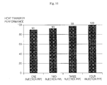
- FIG. 11 is a graph illustrating heat transfer performance based on a number of injection pipes in the heat exchanger of FIG. 10 .
- a plurality of injection pipes 82 A, 82 B and 82 C may be separately provided for the shell 20 so that the heat source fluid may be distributed into a plurality of locations in the shell 20 .
- the plurality of injection pipes 82 A, 82 B and 82 C may be provided together for a single heat exchanger 4 .
- the heat exchanger may further include a branch pipe (not shown) to be connected with the plurality of injection pipes 82 A, 82 B, and 82 C.
- the branch pipe may be connected to the inlet pipe 14 shown in FIG.
- the heat source fluid may be distributed into the plurality of injection pipes 82 A, 82 B, and 82 C from the branch pipe after being introduced into the branch pipe from the inlet pipe 14 , and may be input to the inside of the shell 20 from each of the plurality of injection pipes 82 A, 82 B and 82 C.
- the branch pipe may have one inlet and a plurality of outlets, and a number of the plurality of outlets may correspond to the number of injection pipes 82 A, 82 B, and 82 C.
- the plurality of injection pipes 82 A, 82 B, and 82 C may be configured such that each inlet may be connected to the branch pipe from the outside of the shell 20 .
- the plurality of injection pipes 82 A, 82 B, and 82 C may be configured such that each outlet may be located on the inside of the shell 20 .
- the plurality of injection pipes 82 A, 82 B, and 82 C may have the same diameter or a different diameter. If the plurality of injection pipes has different diameters, the injection pipe having a larger diameter may be disposed to guide the heat source water to the second spiral tube portion 55 of the second refrigerant tube 26 , and the injection pipe having a smaller diameter may be disposed to guide the heat source fluid to the first spiral tube portion 45 of the first refrigerant tube 24 .
- the plurality of injection pipes 82 A, 82 B, and 82 C may be disposed to face the first spiral tube portion 45 of the first refrigerant tube 24 and the second spiral tube portion 55 of the second refrigerant tube 26 , respectively.
- the plurality of injection pipes 82 A, 82 B, and 82 C may be disposed in the shell 20 at regular intervals. For example, if two injection pipes are provided, they may be arranged at approximately 180° intervals. If three injection pipes are provided, they may be arranged at approximately 120° intervals. If four injection pipes are provided, they may be arranged at approximately 90° intervals. Referring to FIG. 11 , the larger the number of injection pipes, the greater the improvement in heat transfer performance. FIG.
- FIG. 11 is a graph illustrating heat transfer performance in a case that various factors, for example, size of the shell 20 , diameters of the injection pipes 82 A, 82 B and 82 C, flow rates may be the same, and the number of the injection pipes 82 A, 82 B, and 82 C and intervals of the water injection pipes 82 A, 82 B, and 82 C may be different, such factors affecting heat transfer performance of the heat exchanger.
- three injection pipes 82 A, 82 B and 82 C may be installed at regular intervals in order to minimize fabricating costs of the heat exchanger and ensure sufficient heat transfer performance.
- FIG. 12 is a schematic longitudinal cross-sectional view of a heat exchanger according to another embodiment.
- FIG. 13 is a side exploded perspective view a plurality of refrigerant tubes in the heat exchanger of FIG. 12 .
- the shell penetration portion penetrating the inner discharge pipe 29 may have a center spiral tube portion 58 .
- the center spiral tube portion 58 may be spirally formed.
- the center spiral tube portion 58 may have a shape such that the plurality of turns is spirally wound around the central vertical axis in succession.
- the center spiral tube portion 58 may have a gap formed between the plurality of turns, the gap being formed in a spiral shape.
- the heat source fluid in the shell 20 may be introduced into the inner space SSS of the inner discharge pipe 29 through a top 29 ′ of the inner discharge pipe 29 .
- the heat source fluid introduced into the inner discharge pipe 29 may be guided to the center spiral tube portion 58 to rotate and flow spirally when passing through the inside of the inner discharge pipe 29 , and may be heat-exchanged with the center spiral tube portion 58 while passing through the inner discharge pipe 29 .
- the center spiral tube portion 58 may be disposed in the inner space SSS of the inner discharge pipe 29 to form the spiral rotating flow path.
- the configuration and operation other than the center spiral tube portion 58 may be equal to or similar to the previous embodiments, repetitive detailed description has been omitted.
- the center spiral tube portion 58 may be formed to extend from each of the plurality of refrigerant tubes 24 and 26 .
- the center spiral tube portion 58 may be formed to extend from only one of the plurality of refrigerant tubes 24 and 26 , and the center spiral tube portion may not be formed on the other one of the plurality of refrigerant tubes 24 and 26 .
- the shell penetration portion 46 of any one of the plurality of refrigerant tubes 24 and 26 , which penetrate the inner discharge pipe 29 may have a straight pipe portion 48 .
- the shell penetration portion 56 of the other one of the plurality of refrigerant tubes 24 and 26 , which penetrates the inner discharge pipe 29 may have the spirally wound center spiral tube portion 58 .
- the heat source fluid introduced into the top 29 ′ of the inner discharge pipe 29 may spirally rotate and flow along the gap of the center spiral tube portion 58 .
- the center spiral tube portion 58 may be a third spiral tube portion distinguished from the first spiral tube portion 45 and the second spiral tube portion 55 .
- the center spiral tube portion 58 may have a smaller radius than the radius of the first spiral tube portion 45 and the second spiral tube portion 55 .
- the center spiral tube portion 58 may be located between an outer peripheral surface of the straight pipe portion 48 and an inner peripheral surface of the inner discharge pipe 29 , and a spiral rotating flow path P may be formed between the straight pipe portion 48 and the inner discharge pipe 29 .
- the center spiral tube portion 58 may contact with the inner peripheral surface of the inner discharge pipe 29 . That is, the outer circumference of the center spiral tube portion 58 may contact the inner peripheral surface of the inner discharge pipe 29 .
- the heat source fluid introduced into the inner space SSS of the inner discharge pipe 29 through the top 29 ′ of the inner discharge pipe 29 may minimize flow between the inner peripheral surface of the inner discharge pipe 29 and the outer circumference of the center spiral tube portion 58 .
- the center spiral tube portion 58 may contact an outer peripheral surface of the straight pipe portion 48 .
- an inner circumference of the center spiral tube portion 58 may contact the outer peripheral surface of the straight pipe portion 48 .
- the heat source fluid introduced into the inner space SSS of the inner discharge pipe 29 ′ through the top 29 of the inner discharge pipe 29 may minimize flow between the outer peripheral surface of the straight pipe portion 48 and the inner circumference of the center spiral tube portion 58 .
- the heat source fluid may be introduced into the inner space SS of the shell 20 through the injection pipe 22 .
- the heat source fluid introduced into the inner space SS of the shell 20 may flow to the upper portion of the inner space SS of the shell 20 from the lower portion of the inner space SS of the shell 20 , may be heat-exchanged with the first spiral tube portion 45 and the second spiral tube portion 55 while being spirally rotating and flowing along the second spiral tube portion 55 as the heat source fluid is elevated.
- the heat source fluid elevated to the upper portion of the inner space SS of the shell 20 may be introduced into the top 29 ′ of the inner discharge pipe 29 .
- the heat source fluid introduced into the top 29 ′ of the inner discharge pipe 29 may spirally rotate and flow along the center spiral tube portion 58 .
- the heat source introduced into the top 29 ′ of the inner discharge pipe 29 may be dropped while being spirally rotating and flowing along the spiral rotating flow path P formed in the inner discharge pipe 29 .
- the center spiral tube portion 58 and the straight pipe portion 48 may be heat-transferred.
- the heat source fluid may flow to the lower portion of the inner space SSS of the inner discharge pipe 29 along the spiral rotating flow path P, and then it may be introduced into the top 30 ′ of the outer discharge pipe 30 from the lower portion of the inner space of the inner discharge pipe 29 .
- the heat source fluid introduced into the top 30 ′ of the outer discharge pipe 30 may pass through the outer discharge pipe 30 .
- FIG. 14 is a schematic longitudinal cross-sectional view of a heat exchanger according to another embodiment.
- FIG. 15 is a schematic internal top view of an injection pipe and a discharge pipe in the heat exchanger of FIG. 14 .
- FIG. 16 is a schematic partial-notched perspective view of an inside of the heat exchanger of FIG. 14 .
- an outlet 93 of an injection pipe 92 may be installed to be opposed to an inner peripheral surface 21 of the hollow shell 32 .
- the configuration and operation other than the injection pipe 92 may be equal to or similar to the previous embodiments, repetitive detailed description has been omitted.
- FIG. 14 shows a singular refrigerant tube 26
- embodiments are not limited to the single refrigerant tube; rather, a plurality of refrigerant tubes may be installed together within one shell 20 . That is, two refrigerant tubes may be installed in one shell 20 , or three or four refrigerant tubes may be installed in one shell 20 .
- the refrigerant tube 26 may include the spiral tube portion 55 , the first shell penetration portion 56 , and the second shell penetration portion 57 .
- the spiral tube portion 55 may be configured such that the plurality of turns 51 , 52 , 53 and 54 may be spirally formed in succession, and the plurality of turns 51 , 52 , 53 and 54 may have the same distance from the central vertical axis X of the spiral tube portion 55 .
- the spiral tube portion 55 may be configured such that the gap 59 may be formed between turns.
- the gap 59 may be spirally formed.
- the heat source fluid may be heat-exchanged with the refrigerant tube 26 while passing through the gap 59 , and fluid may be heat-exchanged with the refrigerant tube 26 while spirally rotating and flowing along the gap 59 .
- a first end of the injection pipe 92 may be located outside of the shell 20 , and a second end thereof may be located inside of the shell 20 . The second end may be located at an upper side of the lower plate 31 .
- the injection pipe 92 may be configured as one member.
- the injection pipe 92 may be configured as an inner injection pipe located inside of the shell 20 and an outer injection pipe located outside of the shell 20 .
- one of the inner injection pipe or the outer discharge pipe may penetrate the lower plate 31 .
- the injection pipe 92 includes the inner injection pipe and the outer injection pipe, one of the inner injection pipe or the outer discharge pipe may be installed to be interposed with the lower plate 31 .
- the injection pipe 92 may be configured such that the first end thereof located outside of the shell 20 is an inlet.
- the injection pipe 92 may be configured such that the second end located at the upper side of the lower plate 31 is an outlet to the inside of the shell 20 .
- a flow direction of the heat source fluid may be determined according to a direction in which the outlet 93 outputs the heat source fluid, that is, a direction by which the heat source fluid is input to the inside of the shell 20 .
- the injection pipe 92 may be disposed such that the heat source fluid may spirally rotate and flow along the inner circumferential surface 21 of the shell 20 .
- the injection pipe 92 may be disposed such that the outlet 93 by which the heat source fluid is input to the inner space SS of the shell 20 may be opposed to the inner circumferential surface 21 of the hollow shell 32 .
- the injection pipe 92 may include an inclined pipe obliquely disposed on the lower plate 31 .
- the inclined pipe may be installed to be obliquely opposed to the inner circumferential surface 21 of the hollow shell 32 .
- the injection pipe 92 may be obliquely installed to have a tilt angle ⁇ of an acute angle with respect to the lower plate 31 .
- the lower plate 31 may be disposed in parallel to a horizontal line H, and the injection pipe 92 may be disposed such that the outlet 93 may have a tilt angle ⁇ of an acute angle with respect to the horizontal line H.
- the injection pipe 92 may be obliquely installed on the lower plate 31 .
- An injection pipe penetration hole 38 ′ formed on the lower plate 31 may be obliquely formed.
- the injection pipe 92 may be installed such that an extension line E does not intersect with the central vertical axis Z of the shell 20 .
- a single or a plurality of injection pipe 92 may be installed in the shell 20 . If a single injection pipe 92 is installed, a plurality of outlets 93 may be installed, and the plurality of outlet 93 may be disposed to be angled with respect to the inner circumferential surface 21 of the shell 20 .
- the heat source fluid may be input to a plurality of locations between the shell 20 and the discharge pipe 28 . If the plurality of injection pipes 92 is installed, each outlet thereof may be installed to be angled with respect to the inner circumferential surface 21 of the shell 20 . If the plurality of injection pipes 92 is installed, they may be separately interposed with the discharge pipe 28 , and at least three injection pipes may be disposed at regular intervals.
- the refrigerant may be introduced into the spiral tube portion 55 through any one of the first shell penetration tube portion 56 or the second shell penetration tube portion 57 , and after sequentially passing through the plurality of turn 51 , 52 , 53 , and 54 of the spiral tube portion 55 , it may pass through any one of the first shell penetration tube portion 56 or the second shell penetration tube portion 57 .
- the heat source fluid may be introduced into the inner space SS of the shell 20 through the injection pipe 92 . When the heat source fluid passes through the outlet 93 from the injection pipe 92 , the input direction may be determined. As the outlet 93 may face the inner circumferential surface 21 of the hollow shell 32 , the heat source fluid may be obliquely input to the inner circumferential surface 21 of the hollow shell 32 .
- the heat source fluid may rotate and flow along the inner circumferential surface 21 of the hollow shell 32 , may rotate and flow in the spiral direction due to centrifugal force, and may contact and be heat-exchanged with the spiral tube portion 55 while rotating and flowing in the spiral direction.
- the spiral tube portion 55 may be heat-exchanged with the heat source fluid using a wider contact area than a case in which the heat source fluid may be upwardly input in the vertical direction so that heat-exchange performance may be improved.
- the heat source fluid may be elevated from the lower portion of the inner space to the upper portion of the inner space SS of the shell 20 while rotating and flowing in the spiral direction, and may be introduced to the upper portion of the inner space SS of the shell 20 , and the flowing heat source fluid may be introduced into the top of the discharge pipe 28 and flow outside of the shell 20 through the discharge pipe 28 .
- FIG. 17 is a schematic internal top view of an injection pipe and a discharge pipe in a heat exchanger according to another embodiment.
- FIG. 18 is a schematic partial-cutout perspective view of an inside of the heat exchanger of FIG. 17 .
- FIG. 19 is a schematic enlarged cross-sectional view of the injection pipe in the heat exchanger of FIG. 17 .
- the injection pipe 102 may include a bent pipe 104 having an outlet 103 , the bent pipe 104 may be formed such that at least a portion thereof may be located inside of the shell 20 , and a curved type flow path C may be formed in an inside thereof.
- the configuration and operation other than the injection pipe 102 may be equal to or similar to the previous embodiment, repetitive detailed description has been omitted.
- the bent pipe 104 may be installed such that the outlet 103 is located inside of the shell 20 .
- the bent pipe 104 may be installed such that the outlet 103 is opposed to the inner peripheral surface 40 of the hollow shell 32 .
- the bent pipe 104 may determine an input direction of the heat source fluid in a direction that the outlet 103 turns.
- the outlet 103 of the bent pipe 104 may be opened in a horizontal direction, or may be opened in an upwardly tilted direction.
- the outlet 103 of the bent pipe 104 may be located between the inner circumferential surface 21 of the hollow shell 32 and the outer peripheral surface of the inner discharge pipe 29 , and the heat source fluid may be input from the outlet 103 to the inner circumferential surface 21 of the hollow shell 32 .
- the outlet 103 may be opened in a direction parallel with a horizontal line or in the upwardly tilted direction having a tilt angle at an acute angle with respect to the horizontal line.
- the outlet 103 may be opened in a direction parallel with a tangential direction of the hollow shell 32 .
- the bent pipe 104 may be disposed to be rotated inside of the shell 20 .
- the bent pipe 104 may be installed to be rotated about a central vertical axis W.
- the bent pipe 104 may be rotated in a direction that the outlet 103 turns along a rotating direction location. If the outlet 103 of the bent pipe 104 is rotated to a location that assures maximum heat-exchange performance, the heat exchanger may maximize the heat-exchange of the heat source fluid with the refrigerant.
- the bent pipe 104 may be installed such the overall outlet 103 is opposed to the inner circumferential surface 21 of the hollow shell 32 , as well as the outer circumferential surface of the inner discharge pipe 29 .
- the injection pipe 102 may be installed such that a lower portion of the bent pipe 104 protrudes from the lower portion of the shell 20 , and the inlet pipe 14 , shown in FIG. 1 , may be connected to the lower portion of the bent pipe 104 . Accordingly, after the heat source fluid guided to the inlet pipe 14 is introduced into the lower portion of the bent pipe 104 , it may be directed toward the inner circumferential surface 21 of the hollow shell 32 through the outlet 103 of the bent pipe 104 .
- the injection pipe 102 may be configured such that the lower portion of the bent pipe 104 is coupled to the injection pipe penetration hole 38 of the lower plate 31 .
- a male screw may be formed on a lower outer circumference of the bent pipe 104
- a female screw may be formed on the injection pipe penetration hole 38 .
- the injection pipe 102 may be configured such that the lower portion of the bent pipe 104 is inserted into the injection pipe penetration hole 38 while the bent pipe 104 is rotated.
- rotating of the bent pipe 104 may be stopped.
- rotating of the bent pipe 104 may be stopped.
- the injection pipe 102 may further include an outer injection pipe 106 at least a portion of which may be located outside of the shell 20 , and the heat source fluid may be guided to the bent pipe 104 .
- the injection pipe 102 may include both the bent pipe 104 and the outer injection pipe 106 , and after the heat source fluid may be guided to the outer injection pipe 106 may be guided to the bent pipe 104 , it may be input to the inner space SS of the shell 20 . If the injection pipe 102 includes both the bent pipe 104 and the outer injection pipe 106 , each of the bent pipe 104 and the outer injection pipe 106 may be, for example, welded to the lower plate 31 .
- one of the bent pipe 104 or the outer injection pipe 106 may be, for example, welded to or combined with the lower plate 31 to be fixed to the lower plate 31 , the bent pipe 104 and the outer injection pipe 106 may be coupled to be connected to each other, and the bent pipe 104 and the outer injection pipe 106 may be combined or welded.
- the outer injection pipe 106 may penetrate the lower plate 31 such that the upper portion is located on the inside of the shell 20 , and the bent pipe 104 may be configured such that the lower portion of the bent pipe 104 , for example, combined with or welded to the upper portion of the outer injection pipe 106 in a state that the overall pipe is located inside of the shell 20 .
- the injection pipe 102 may include a spiral groove 108 formed on an inner circumference thereof.
- the spiral groove 108 may be formed on at least an inner circumference of the bent pipe 104 or the outer injection pipe 106 . If the spiral groove 108 is formed on the inner circumference of the outer injection pipe 106 , the heat source fluid guided to the inside of the outer injection pipe 106 may be introduced into the bent pipe 104 while spirally rotating and flowing along the spiral groove 108 of the outer injection pipe 106 , and may be input to the shell 20 by passing through the bent pipe 104 and maintaining spiral rotating and flowing due to the centrifugal force.
- the flowing direction may be converted in the tilt direction, which is approximately horizontal or closer to the horizontal, and the heat source fluid may be input toward the inner circumferential surface 21 of the hollow shell 32 by passing through the outlet 103 of the bent pipe 104 .
- the heat source fluid input through the outlet 103 of the bent pipe 104 may flow by spiral rotating and flowing between the hollow shell 32 and the inner discharge pipe 29 while rotating along the inner circumferential surface 21 of the hollow shell 32 .
- the heat source fluid may be elevated while rotating and flowing to the upper portion of the inner space SS of the shell 20 in the spiral direction, as described in the previous embodiment, and the heat source fluid flowing to the upper portion of the inner space SS of the shell 20 may be introduced into the top of the inner discharge pipe 29 and flow to the outside of the shell 20 through the discharge pipe 28 .
- FIG. 20 is a schematic partial longitudinal cross-sectional view of a heat exchanger according to another embodiment of.
- an upper guide 110 may be formed on the upper plate 33 , the upper guide 110 inducing the heat source fluid to the top 29 ′ of the discharge pipe 28 .
- the upper guide 110 may downwardly protrude in a conical shape from the upper plate 33 .
- the configuration and operation other than the upper guide 110 may be equal to or similar to the previous embodiment, repetitive detailed description has been omitted.
- the heat source fluid introduced inside of the shell 20 from the injection pipe may be elevated while spirally rotating and flowing along the inner circumferential surface 21 of the hollow shell 32 , as described in the previous embodiments, and the heat source fluid flowing to the upper portion of the inner space SS of the shell 20 may be guided to the upper guide 110 to be induced into the top 29 ′ of the discharge pipe 28 .
- the heat source fluid guided to the upper guide 110 does not hover around or at the upper side location of the top 29 ′ of the discharge pipe 28 , may pass through the top 29 ′ of the discharge pipe 28 , and may be dropped to the inside of the discharge pipe 28 to flow outside of the shell 20 through the discharge pipe 28 .
- FIG. 21 is a schematic longitudinal cross-sectional view of a heat exchanger according to another embodiment.
- a heat source fluid guide 120 may be formed in the shell 20 , the heat source fluid guide 120 guiding the heat source fluid to the refrigerant tube 26 .
- the configuration and operation other than the heat source fluid guide 120 may be equal to or similar to the previous embodiment, repetitive detailed description has been omitted.
- the heat source fluid guide 120 may be formed on the inner circumferential surface 21 of the shell 20 .
- the heat source fluid guide 120 may be formed in the hollow shell 32 , and may be formed on the inner circumferential surface 21 of the hollow shell 32 .
- the heat source fluid guide 120 may be configured such that the discharge of the heat source fluid without heat-exchanging may be minimized by guiding the heat source fluid introduced into the inside of the shell 20 through the injection pipe 22 to the spiral tube portion 55 of the refrigerant tube 26 .
- the heat source fluid guide 120 may protrude toward the gap 59 of the spiral tube portion 55 .
- the heat source fluid guide 120 may protrude from the inner circumferential surface 21 of the hollow shell toward the gap 59 of the refrigerant tube 26 .
- the heat source fluid may be induced to the gap 59 by the heat source fluid guide 120 , and the heat source fluid induced to the gap 59 may be heat-exchanged with the lower portion of the turn 52 located on the upper side of the gap 59 and the upper portion of the turn 53 located on the upper side of the gap 59 using a wider heat transfer area.
- the heat source fluid guide 120 may be spirally vertically-formed on the inner circumferential surface 21 of the shell 20 .
- the heat source fluid guide 120 may be configured such that a portion 121 is inserted into the gap 59 .
- the heat source fluid guide 120 may have a curved surface 122 of a shape surrounding a portion of the turn.
- FIG. 21 shows a plurality of refrigerant tubes 24 and 26
- embodiments are not so limited. That is, a single refrigerant tube 26 may be installed in the shell 20 , two refrigerant tubes may be installed in one shell 20 , or three or four refrigerant tubes may be installed in one shell 20 , for example.
- the plurality of refrigerant tubes 24 and 26 may include the first refrigerant tube 24 and the second refrigerant tube 26 , and the heat source fluid guide 120 may protrude toward the gap 59 formed on the second spiral tube portion 55 of the second refrigerant tube 26 .
- the heat source fluid introduced inside of the shell 20 from the injection pipe 22 may be guided to the heat source fluid guide 120 to pass through the gap 59 formed in the spiral tube portion 55 of the second refrigerant tube 26 .
- the heat source fluid passing through the gap 59 may contact with the spiral tube portion 45 of the first refrigerant tube 24 at a location between the gap 59 and the discharge pipe 28 , and may be heat-exchanged with the spiral tube portion 45 of the first refrigerant tube 24 .
- the heat source fluid may be guided to the heat source fluid guide 120 between the spiral tube portion 45 of the first refrigerant tube 24 and the inner circumferential surface 21 of the shell 20 and may be elevated while rotating and flowing spirally.
- the heat source fluid may be heat-exchanged with the first refrigerant tube 24 and the second refrigerant tube 26 , respectively, using a maximally wider contact area, while rotating and flowing spirally.
- the heat source fluid heat-exchanged with the first refrigerant tube 24 and the second refrigerant tube 26 may introduced into the discharge pipe 28 from the upper portion of the inner space SS of the shell 20 after being elevated to the upper portion of the inner space SS of the shell 20 , and may flow to the outside of the shell 20 through the discharge pipe 28 .
- Embodiments disclosed herein provide a heat exchanger having a simple structure and improved heat-exchange performance. Further, embodiments disclosed herein provide a compact heat exchanger.
- Embodiments disclosed herein provide a heat exchanger that may include a shell, a water injection pipe or injection pipe to guide a heat source fluid, such as water, to an inside of the shell, a first refrigerant tube formed with a first spiral tube portion, a second refrigerant tube formed with a second spiral tube portion having a radius larger than a radius of the first spiral tube portion, and a water discharge pipe or discharge pipe to which the heat source water heat-exchanged with a refrigerant may be discharged.
- the first refrigerant tube and the second refrigerant tube may be connected in parallel.
- the second spiral tube portion may have a larger pitch between turns and a smaller number of turns than those of the first spiral tube portion.
- the pitch between turns of the second spiral tube portion may be approximately 1.3 to 1.5 times the pitch between turns of the first spiral tube portion.
- the second spiral tube portion may be disposed between the first spiral tube portion and the shell.
- the first spiral tube portion and the second spiral tube portion may be long-disposed inside of the shell in an up and down direction or vertically disposed within the shell.
- a vertical center axis or central vertical axis of the first spiral tube portion may correspond with a vertical center axis or central vertical axis of the second spiral tube portion.
- At least one of the first spiral tube portion or the second spiral tube portion may have at least one protruding fin.
- the water injection pipe may distribute and introduce the heat source water into the inside of the shell.
- a plurality of water injection pipes may be disposed to be separated from each other, and the heat source water may be guided to a plurality of locations in the inside of the shell.
- the water discharge pipe may include an inner water discharge pipe located on the inside of the shell, and an outer water discharge pipe to which the heat source water in the inner water discharge pipe is discharged and guided and which has a flow path cross-sectional area smaller than a flow path cross-sectional area of the inner water discharge pipe
- the first spiral tube portion may be located between the inner water discharge pipe and an inner peripheral surface of the shell.
- the second spiral tube portion may be disposed between the first spiral tube portion and the inner peripheral surface of the shell.
- the first refrigerant tube may include a shell penetration portion that extends from one side of the first spiral tube portion and penetrates the inner water discharge pipe.
- Any one of the shell penetration portion of the first refrigerant tube or the shell penetration portion of the second refrigerant tube may be formed with a straight pipe portion, and the other one of the shell penetration portion of the first refrigerant tube or the shell penetration portion of the second refrigerant tube may be formed with a third spiral tube portion located between the outer peripheral surface of the straight pipe portion and the inner peripheral surface of the inner water discharge pipe and spirally wound.
- the shell further may include a lower plate, a hollow shell disposed on an upper side of the lower plate, and an upper plate disposed on an upper side of the hollow shell.
- the water injection pipe may be disposed on the lower plate, and the water injection pipe may have an outlet that obliquely faces an inner peripheral surface of the hollow shell.
- the shell may be formed with a heat source water guide that protrudes to a gap of the second spiral tube portion.
- Embodiments disclosed herein provide at least the following advantages.
- first refrigerant tube and the second refrigerant tube may have the same flow path or a difference in the flow paths may be minimized, it is possible to prevent performance degradation that may occur when the first refrigerant tube and the second refrigerant tube have different flow paths, using a simple structure.
- Embodiments disclosed herein further provide a compact heat exchanger as even if a flow path area or length of the refrigerant tube is larger, the shell penetration tube portion of the refrigerant tube may pass through the inside of the inner water discharge pipe.
- Embodiments disclosed herein provide a heat exchanger having increased heat-exchange performance as the heat source water passing through the inner water discharge pipe may be heat-exchanged with the refrigerant additionally.
- Embodiments disclosed herein provide a heat exchanger, in which heat-exchange performance may be maximized, as the heat source water introduced into the inner water discharge pipe may be heat-exchanged with the refrigerant while spirally rotating and flowing to the inside of the inner water discharge pipe.
- Embodiments disclosed herein provide a heat exchanger having increased heat-exchange performance as the heat source water introduced into the inside of the shell through the water injection pipe may accelerate the rotation flow while turning along the inner peripheral surface of the hollow shell.
- Embodiments disclosed herein provide a heat exchanger in which heat transfer time and heat transfer area may be maximized, as the heat source water may be heat-exchanged with the spiral tube portion while spirally rotating and flowing.
- Embodiments disclosed herein provide a heat exchanger having increase heat-exchange performance using simple structure in which the water injection pipe is configured as an inclined pipe or a bent pipe, without installing a separate baffle to determine or control a flow direction of the heat source water.
- Embodiments disclosed herein provide a heat exchanger in which the heat source water may be induced into a gap of the spiral tube portion by a heat source water guide that protrudes from the shell, such that the heat source water may be maximally heat-exchanged with the spiral tube portion and then may be discharged, without installing a separate baffle to induce the heat source water flow, by a simple structure.
- any reference in this specification to “one embodiment,” “an embodiment,” “example embodiment,” etc. means that a particular feature, structure, or characteristic described in connection with the embodiment is included in at least one embodiment of the invention.
- the appearances of such phrases in various places in the specification are not necessarily all referring to the same embodiment.
Applications Claiming Priority (12)
| Application Number | Priority Date | Filing Date | Title |
|---|---|---|---|
| KR10-2013-11838 | 2013-02-01 | ||
| KR1020130011837A KR20140099069A (ko) | 2013-02-01 | 2013-02-01 | 열교환기 |
| KR10-2013-11836 | 2013-02-01 | ||
| KR10-2013-11839 | 2013-02-01 | ||
| KR1020130011839A KR101582580B1 (ko) | 2013-02-01 | 2013-02-01 | 열교환기 |
| KR10-2013-11837 | 2013-02-01 | ||
| KR1020130011836A KR20140099380A (ko) | 2013-02-01 | 2013-02-01 | 열교환기 |
| KR10-2013-0011839 | 2013-02-01 | ||
| KR1020130011838A KR101546903B1 (ko) | 2013-02-01 | 2013-02-01 | 열교환기 |
| KR10-2013-0011836 | 2013-02-01 | ||
| KR10-2013-0011838 | 2013-02-01 | ||
| KR10-2013-0011837 | 2013-02-01 |
Publications (2)
| Publication Number | Publication Date |
|---|---|
| US20140216699A1 US20140216699A1 (en) | 2014-08-07 |
| US9677819B2 true US9677819B2 (en) | 2017-06-13 |
Family
ID=49626810
Family Applications (1)
| Application Number | Title | Priority Date | Filing Date |
|---|---|---|---|
| US14/089,951 Active 2035-10-06 US9677819B2 (en) | 2013-02-01 | 2013-11-26 | Air conditioner and heat exchanger therefor |
Country Status (3)
| Country | Link |
|---|---|
| US (1) | US9677819B2 (es) |
| EP (2) | EP2762820B1 (es) |
| ES (1) | ES2574429T3 (es) |
Cited By (2)
| Publication number | Priority date | Publication date | Assignee | Title |
|---|---|---|---|---|
| US11243033B2 (en) * | 2019-11-26 | 2022-02-08 | Noritz Corporation | Heat exchanger and water heating apparatus including same |
| US11421548B2 (en) * | 2018-12-05 | 2022-08-23 | Airbus Operations S.A.S. | Aircraft engine assembly with boundary layer ingestion including an electric motor and a cooling system partially arranged in the exhaust cone |
Families Citing this family (10)
| Publication number | Priority date | Publication date | Assignee | Title |
|---|---|---|---|---|
| AU2009224115B2 (en) * | 2008-03-10 | 2014-09-04 | Hot Water Ip Limited | Heat pump water heater |
| CN104209381B (zh) * | 2014-09-12 | 2016-02-17 | 张家港市华机环保新能源科技有限公司 | 一种汽化器弯管用设备 |
| AT516385B1 (de) * | 2015-06-23 | 2016-05-15 | Avl List Gmbh | Temperiereinheit für ein gasförmiges oder flüssiges Medium |
| KR102491602B1 (ko) * | 2015-10-23 | 2023-01-25 | 삼성전자주식회사 | 공기조화기 |
| CN105953434B (zh) * | 2016-06-15 | 2019-05-10 | 佛山光腾新能源股份有限公司 | 热泵热水器换热器 |
| CN106225329A (zh) * | 2016-08-31 | 2016-12-14 | 桑小飞 | 壳式热交换器、水冷外挂模组及水冷系统 |
| DE102017209728A1 (de) * | 2017-06-08 | 2018-12-13 | Volkswagen Aktiengesellschaft | Vorrichtung zur Wärmerückgewinnung |
| CN109280618A (zh) * | 2018-10-12 | 2019-01-29 | 南京和润隆环保科技有限公司 | 一种推流反应器进料预加热装置 |
| CN111089433B (zh) * | 2019-04-09 | 2020-10-23 | 山东大学 | 一种控制蒸发器脉动流大小的制冷系统 |
| JP7330583B1 (ja) | 2023-03-27 | 2023-08-22 | ファインマシーンカタオカ株式会社 | 熱交換器 |
Citations (65)
| Publication number | Priority date | Publication date | Assignee | Title |
|---|---|---|---|---|
| US1343669A (en) * | 1917-10-31 | 1920-06-15 | Murray & Tregurtha Company | Oil-cooling apparatus |
| GB152276A (en) | 1920-04-10 | 1920-10-14 | Clyde Valley Shipwelders Ltd | An improved oxy-acetylene cutting torch |
| US1526320A (en) | 1922-03-20 | 1925-02-17 | Chauncey B Forward | Heat exchanger |
| US1840940A (en) | 1927-10-13 | 1932-01-12 | Baker Ice Machine Co Inc | Refrigeration unit |
| US1940964A (en) | 1931-01-21 | 1933-12-26 | Patrick J Mcintyre | Radiator construction |
| US2125972A (en) | 1936-07-11 | 1938-08-09 | Kellogg M W Co | Heat exchanger |
| US2288251A (en) | 1940-12-31 | 1942-06-30 | Bell Telephone Labor Inc | Automatic toll switching telephone system |
| US2534690A (en) | 1945-09-10 | 1950-12-19 | Hughes Tool Co | Tube support |
| US2566976A (en) | 1949-11-09 | 1951-09-04 | Clarence R Bernstrom | Water heater |
| US2761430A (en) | 1952-09-22 | 1956-09-04 | Frank W Schaefer | Boiler mounting |
| US2805048A (en) | 1954-01-12 | 1957-09-03 | Henry W Angelery | Coil structure for heat exchanger |
| GB811665A (en) | 1956-07-09 | 1959-04-08 | Ici Ltd | Heat exchanger |
| DE1078145B (de) | 1957-10-23 | 1960-03-24 | Adam Elmer Dipl Ing | Rohrschlangenwaermetauscher mit mehreren schraubenlinienfoermig gewundenen und um eine mittlere Tragsaeule angeordneten Rohrschlangen |
| US3199583A (en) | 1962-08-10 | 1965-08-10 | Cryovac Inc | Spiral tube heat exchanger |
| US3332477A (en) * | 1965-01-05 | 1967-07-25 | Richmond Engineering Company I | Water heating apparatus |
| US3341122A (en) | 1965-03-30 | 1967-09-12 | Raypak Company Inc | Integrated hydronic heating system |
| DE1952861A1 (de) | 1969-06-20 | 1971-04-29 | Georg Lohse | Waermeaustauscher |
| DE1679737A1 (de) * | 1965-11-11 | 1971-05-13 | Hovalwerk Ag Ospelt | Brauchwasserbereiter |
| DE1679733A1 (de) | 1965-09-21 | 1972-01-13 | Nova Apparatebau Kg | Warmwasserbereiter |
| FR2155770A1 (en) * | 1971-10-04 | 1973-05-25 | Ind Chauffage | Spiral tube heat exchanger - with tubes contacting shell to define shell-side flow |
| US3817688A (en) | 1973-02-16 | 1974-06-18 | Fedders Corp | Pipe mounting clip arrangement |
| GB1387571A (en) | 1972-01-20 | 1975-03-19 | Asw Apparatenfabriek Nv | Fluid heating system |
| US4152015A (en) | 1977-06-21 | 1979-05-01 | Cameron Iron Works, Inc. | Casing hanger |
| US4202406A (en) | 1978-06-29 | 1980-05-13 | Avery Alfred J | Heat exchange system |
| US4313491A (en) | 1978-06-30 | 1982-02-02 | Molitor Industries, Inc. | Coiled heat exchanger |
| US4471836A (en) | 1982-01-15 | 1984-09-18 | Arthur C. Knox, Jr. | Vent condenser |
| US4570452A (en) * | 1982-09-22 | 1986-02-18 | Thermal Concepts, Inc. | Earth-type heat exchanger for heat pump systems |
| WO1988001362A1 (en) | 1986-08-21 | 1988-02-25 | Emil Bader | Countercurrent heat-exchanger with helical bank of tubes |
| EP0261005A1 (fr) | 1986-08-28 | 1988-03-23 | Automobiles Peugeot | Dispositif pour le réchauffage du liquide d'un lave-glace de véhicule automobile |
| DE8715522U1 (es) | 1987-11-24 | 1988-05-19 | Fischer, Guenther, 6000 Frankfurt, De | |
| US5046548A (en) * | 1987-10-20 | 1991-09-10 | Leif Tilly | Device for preparing putty and similar masses |
| JPH0684167A (ja) | 1992-08-31 | 1994-03-25 | Sony Corp | 磁気記録媒体及びその製造方法 |
| US5379832A (en) | 1992-02-18 | 1995-01-10 | Aqua Systems, Inc. | Shell and coil heat exchanger |
| EP0819892A2 (de) | 1996-07-17 | 1998-01-21 | KME Schmöle GmbH | Wärmetauscher zur Brauchwasserbereitung |
| EP0845640A1 (de) | 1996-11-28 | 1998-06-03 | Nefit Fasto B.V. | Zylindrische Heizungsvorrichtung mit schraubenlinienförmigem Wärmeübertrager |
| KR19990076959A (ko) | 1996-11-01 | 1999-10-25 | 요한 델크 브로우버 | 가열 장치 및 그 작동 방법 |
| JP2000055574A (ja) | 1998-08-12 | 2000-02-25 | Orion Mach Co Ltd | 熱交換装置 |
| US6095240A (en) | 1998-07-01 | 2000-08-01 | Vita International, Inc. | Quadruple heat exchanger |
| US6102106A (en) | 1997-12-31 | 2000-08-15 | Flowserve Management Company | Method of servicing a helical coil heat exchanger with removable end plates |
| KR20010029372A (ko) | 1999-09-30 | 2001-04-06 | 황한규 | 차량용 에어컨의 리시버 드라이어 |
| JP2002195767A (ja) | 2000-12-21 | 2002-07-10 | Komatsu Ltd | 熱交換処理装置 |
| KR100353334B1 (ko) | 1994-03-07 | 2003-02-07 | 둔함-부쉬 인터내셔널 (케이만) 리미티드 오브 브리티쉬 아메리 칸 센터 | 열교환기요소및이를사용한열교환기 |
| WO2003023306A1 (fr) | 2001-09-06 | 2003-03-20 | Kyowa Hakko Kogyo Co., Ltd. | Tube d'aspiration et tour de fractionnement |
| WO2003087677A2 (en) | 2002-04-10 | 2003-10-23 | S.S. Rustfri A/S | A condensation vessel and method of condensation of a refrigerant |
| JP2004144366A (ja) | 2002-10-23 | 2004-05-20 | Matsushita Electric Ind Co Ltd | 温水熱交換器内蔵型貯湯タンクユニット |
| KR20040111678A (ko) | 2003-03-11 | 2004-12-31 | 위에 장 | 흡수식 공조기 본체 |
| US20060005955A1 (en) | 2004-07-12 | 2006-01-12 | Orr Troy J | Heat exchanger apparatus and methods for controlling the temperature of a high purity, re-circulating liquid |
| WO2006105605A1 (en) | 2005-04-07 | 2006-10-12 | Baker, Alan, Paul | Improvements in control of heat exchangers |
| EP1750070A1 (en) | 2005-08-05 | 2007-02-07 | Riello S.p.a. | Heat exchanger with finned tube and method of producing the same |
| DE102007002051A1 (de) | 2006-01-19 | 2007-07-26 | Vaillant Gmbh | Vorrichtung zur Wärmerückgewinnung aus Abwasser sowie ein Verfahren zum Betreiben dieser Vorrichtung |
| EP1813882A1 (fr) | 2006-01-30 | 2007-08-01 | Joseph Le Mer | Echangeur de chaleur à condensation |
| KR20070094792A (ko) | 2004-12-18 | 2007-09-21 | 노이에 에네르기-페르베르텅스게셀쉐프트 엠베하 | 열교환기 |
| JP2007278688A (ja) | 2006-04-06 | 2007-10-25 | Visteon Global Technologies Inc | 螺旋形規格化フィンチューブを持つ内部熱交換器 |
| JP2007333319A (ja) | 2006-06-15 | 2007-12-27 | Daikin Ind Ltd | 熱交換器 |
| US7458222B2 (en) | 2004-07-12 | 2008-12-02 | Purity Solutions Llc | Heat exchanger apparatus for a recirculation loop and related methods and systems |
| US20090025399A1 (en) | 2007-06-07 | 2009-01-29 | Deka Produsts Limited Partnership | Water Vapor Distillation Apparatus, Method and System |
| US7549462B2 (en) | 2002-01-21 | 2009-06-23 | Rhodia Polyamide Intermediates | Coil for coolant circulation, method for making same and reactor comprising same |
| KR20090095253A (ko) | 2008-03-05 | 2009-09-09 | 주식회사 한국피이엠 | 지열 회수용 코일형 합성수지관 및 그 제조방법 |
| US20100017952A1 (en) | 2007-04-03 | 2010-01-28 | Global Heating Solutions, Inc. | Spa having heat pump system |
| US7669644B2 (en) * | 2004-01-22 | 2010-03-02 | Cosmogas S.R.L. | Heat exchanger, in particular of the condensation type |
| KR20110088913A (ko) | 2010-01-29 | 2011-08-04 | 주식회사 엔에코 | 세라믹층이 형성된 빙축시스템을 이용한 정수기용 냉수 열교환기 |
| KR20110128709A (ko) | 2010-05-24 | 2011-11-30 | 주식회사 제이 티 씨 | 열교환기의 튜브와 튜브 시트의 조립 방법 |
| JP2012072936A (ja) | 2010-09-28 | 2012-04-12 | Orion Machinery Co Ltd | クーラントチラー用熱交換器 |
| EP2505932A1 (en) | 2009-11-27 | 2012-10-03 | Guangdong ROC Cool & Heat Equipment Co., Ltd. | Condensing-type heat exchanger with high efficiency |
| US9389026B2 (en) * | 2012-07-11 | 2016-07-12 | Lg Electronics Inc. | Heat exchanger |
-
2013
- 2013-11-15 EP EP13193106.5A patent/EP2762820B1/en active Active
- 2013-11-15 ES ES13193106.5T patent/ES2574429T3/es active Active
- 2013-11-26 US US14/089,951 patent/US9677819B2/en active Active
-
2014
- 2014-01-16 EP EP14151438.0A patent/EP2762821B1/en active Active
Patent Citations (66)
| Publication number | Priority date | Publication date | Assignee | Title |
|---|---|---|---|---|
| US1343669A (en) * | 1917-10-31 | 1920-06-15 | Murray & Tregurtha Company | Oil-cooling apparatus |
| GB152276A (en) | 1920-04-10 | 1920-10-14 | Clyde Valley Shipwelders Ltd | An improved oxy-acetylene cutting torch |
| US1526320A (en) | 1922-03-20 | 1925-02-17 | Chauncey B Forward | Heat exchanger |
| US1840940A (en) | 1927-10-13 | 1932-01-12 | Baker Ice Machine Co Inc | Refrigeration unit |
| US1940964A (en) | 1931-01-21 | 1933-12-26 | Patrick J Mcintyre | Radiator construction |
| US2125972A (en) | 1936-07-11 | 1938-08-09 | Kellogg M W Co | Heat exchanger |
| US2288251A (en) | 1940-12-31 | 1942-06-30 | Bell Telephone Labor Inc | Automatic toll switching telephone system |
| US2534690A (en) | 1945-09-10 | 1950-12-19 | Hughes Tool Co | Tube support |
| US2566976A (en) | 1949-11-09 | 1951-09-04 | Clarence R Bernstrom | Water heater |
| US2761430A (en) | 1952-09-22 | 1956-09-04 | Frank W Schaefer | Boiler mounting |
| US2805048A (en) | 1954-01-12 | 1957-09-03 | Henry W Angelery | Coil structure for heat exchanger |
| GB811665A (en) | 1956-07-09 | 1959-04-08 | Ici Ltd | Heat exchanger |
| DE1078145B (de) | 1957-10-23 | 1960-03-24 | Adam Elmer Dipl Ing | Rohrschlangenwaermetauscher mit mehreren schraubenlinienfoermig gewundenen und um eine mittlere Tragsaeule angeordneten Rohrschlangen |
| US3199583A (en) | 1962-08-10 | 1965-08-10 | Cryovac Inc | Spiral tube heat exchanger |
| US3332477A (en) * | 1965-01-05 | 1967-07-25 | Richmond Engineering Company I | Water heating apparatus |
| US3341122A (en) | 1965-03-30 | 1967-09-12 | Raypak Company Inc | Integrated hydronic heating system |
| DE1679733A1 (de) | 1965-09-21 | 1972-01-13 | Nova Apparatebau Kg | Warmwasserbereiter |
| DE1679737A1 (de) * | 1965-11-11 | 1971-05-13 | Hovalwerk Ag Ospelt | Brauchwasserbereiter |
| DE1952861A1 (de) | 1969-06-20 | 1971-04-29 | Georg Lohse | Waermeaustauscher |
| FR2155770A1 (en) * | 1971-10-04 | 1973-05-25 | Ind Chauffage | Spiral tube heat exchanger - with tubes contacting shell to define shell-side flow |
| GB1387571A (en) | 1972-01-20 | 1975-03-19 | Asw Apparatenfabriek Nv | Fluid heating system |
| US3817688A (en) | 1973-02-16 | 1974-06-18 | Fedders Corp | Pipe mounting clip arrangement |
| US4152015A (en) | 1977-06-21 | 1979-05-01 | Cameron Iron Works, Inc. | Casing hanger |
| US4202406A (en) | 1978-06-29 | 1980-05-13 | Avery Alfred J | Heat exchange system |
| US4313491A (en) | 1978-06-30 | 1982-02-02 | Molitor Industries, Inc. | Coiled heat exchanger |
| US4471836A (en) | 1982-01-15 | 1984-09-18 | Arthur C. Knox, Jr. | Vent condenser |
| US4570452A (en) * | 1982-09-22 | 1986-02-18 | Thermal Concepts, Inc. | Earth-type heat exchanger for heat pump systems |
| WO1988001362A1 (en) | 1986-08-21 | 1988-02-25 | Emil Bader | Countercurrent heat-exchanger with helical bank of tubes |
| US4893672A (en) | 1986-08-21 | 1990-01-16 | Bader Emil E | Counter-flow heat exchanger with helical tube bundle |
| EP0261005A1 (fr) | 1986-08-28 | 1988-03-23 | Automobiles Peugeot | Dispositif pour le réchauffage du liquide d'un lave-glace de véhicule automobile |
| US5046548A (en) * | 1987-10-20 | 1991-09-10 | Leif Tilly | Device for preparing putty and similar masses |
| DE8715522U1 (es) | 1987-11-24 | 1988-05-19 | Fischer, Guenther, 6000 Frankfurt, De | |
| US5379832A (en) | 1992-02-18 | 1995-01-10 | Aqua Systems, Inc. | Shell and coil heat exchanger |
| JPH0684167A (ja) | 1992-08-31 | 1994-03-25 | Sony Corp | 磁気記録媒体及びその製造方法 |
| KR100353334B1 (ko) | 1994-03-07 | 2003-02-07 | 둔함-부쉬 인터내셔널 (케이만) 리미티드 오브 브리티쉬 아메리 칸 센터 | 열교환기요소및이를사용한열교환기 |
| EP0819892A2 (de) | 1996-07-17 | 1998-01-21 | KME Schmöle GmbH | Wärmetauscher zur Brauchwasserbereitung |
| KR19990076959A (ko) | 1996-11-01 | 1999-10-25 | 요한 델크 브로우버 | 가열 장치 및 그 작동 방법 |
| EP0845640A1 (de) | 1996-11-28 | 1998-06-03 | Nefit Fasto B.V. | Zylindrische Heizungsvorrichtung mit schraubenlinienförmigem Wärmeübertrager |
| US6102106A (en) | 1997-12-31 | 2000-08-15 | Flowserve Management Company | Method of servicing a helical coil heat exchanger with removable end plates |
| US6095240A (en) | 1998-07-01 | 2000-08-01 | Vita International, Inc. | Quadruple heat exchanger |
| JP2000055574A (ja) | 1998-08-12 | 2000-02-25 | Orion Mach Co Ltd | 熱交換装置 |
| KR20010029372A (ko) | 1999-09-30 | 2001-04-06 | 황한규 | 차량용 에어컨의 리시버 드라이어 |
| JP2002195767A (ja) | 2000-12-21 | 2002-07-10 | Komatsu Ltd | 熱交換処理装置 |
| WO2003023306A1 (fr) | 2001-09-06 | 2003-03-20 | Kyowa Hakko Kogyo Co., Ltd. | Tube d'aspiration et tour de fractionnement |
| US7549462B2 (en) | 2002-01-21 | 2009-06-23 | Rhodia Polyamide Intermediates | Coil for coolant circulation, method for making same and reactor comprising same |
| WO2003087677A2 (en) | 2002-04-10 | 2003-10-23 | S.S. Rustfri A/S | A condensation vessel and method of condensation of a refrigerant |
| JP2004144366A (ja) | 2002-10-23 | 2004-05-20 | Matsushita Electric Ind Co Ltd | 温水熱交換器内蔵型貯湯タンクユニット |
| KR20040111678A (ko) | 2003-03-11 | 2004-12-31 | 위에 장 | 흡수식 공조기 본체 |
| US7669644B2 (en) * | 2004-01-22 | 2010-03-02 | Cosmogas S.R.L. | Heat exchanger, in particular of the condensation type |
| US7458222B2 (en) | 2004-07-12 | 2008-12-02 | Purity Solutions Llc | Heat exchanger apparatus for a recirculation loop and related methods and systems |
| US20060005955A1 (en) | 2004-07-12 | 2006-01-12 | Orr Troy J | Heat exchanger apparatus and methods for controlling the temperature of a high purity, re-circulating liquid |
| KR20070094792A (ko) | 2004-12-18 | 2007-09-21 | 노이에 에네르기-페르베르텅스게셀쉐프트 엠베하 | 열교환기 |
| WO2006105605A1 (en) | 2005-04-07 | 2006-10-12 | Baker, Alan, Paul | Improvements in control of heat exchangers |
| EP1750070A1 (en) | 2005-08-05 | 2007-02-07 | Riello S.p.a. | Heat exchanger with finned tube and method of producing the same |
| DE102007002051A1 (de) | 2006-01-19 | 2007-07-26 | Vaillant Gmbh | Vorrichtung zur Wärmerückgewinnung aus Abwasser sowie ein Verfahren zum Betreiben dieser Vorrichtung |
| EP1813882A1 (fr) | 2006-01-30 | 2007-08-01 | Joseph Le Mer | Echangeur de chaleur à condensation |
| JP2007278688A (ja) | 2006-04-06 | 2007-10-25 | Visteon Global Technologies Inc | 螺旋形規格化フィンチューブを持つ内部熱交換器 |
| JP2007333319A (ja) | 2006-06-15 | 2007-12-27 | Daikin Ind Ltd | 熱交換器 |
| US20100017952A1 (en) | 2007-04-03 | 2010-01-28 | Global Heating Solutions, Inc. | Spa having heat pump system |
| US20090025399A1 (en) | 2007-06-07 | 2009-01-29 | Deka Produsts Limited Partnership | Water Vapor Distillation Apparatus, Method and System |
| KR20090095253A (ko) | 2008-03-05 | 2009-09-09 | 주식회사 한국피이엠 | 지열 회수용 코일형 합성수지관 및 그 제조방법 |
| EP2505932A1 (en) | 2009-11-27 | 2012-10-03 | Guangdong ROC Cool & Heat Equipment Co., Ltd. | Condensing-type heat exchanger with high efficiency |
| KR20110088913A (ko) | 2010-01-29 | 2011-08-04 | 주식회사 엔에코 | 세라믹층이 형성된 빙축시스템을 이용한 정수기용 냉수 열교환기 |
| KR20110128709A (ko) | 2010-05-24 | 2011-11-30 | 주식회사 제이 티 씨 | 열교환기의 튜브와 튜브 시트의 조립 방법 |
| JP2012072936A (ja) | 2010-09-28 | 2012-04-12 | Orion Machinery Co Ltd | クーラントチラー用熱交換器 |
| US9389026B2 (en) * | 2012-07-11 | 2016-07-12 | Lg Electronics Inc. | Heat exchanger |
Non-Patent Citations (20)
| Title |
|---|
| European Search Report dated Dec. 11, 2014. (Full English Text). |
| European Search Report dated May 13, 2014 issued in Application No. 13 193 106.5. |
| European Search Report dated May 13, 2014 issued in Application No. 14 151 438.0. |
| European Search Report dated Nov. 21, 2014. (Full English Text). |
| European Search Report dated Sep. 24, 2013. |
| Korean Office Action dated Aug. 30, 2013. |
| Korean Office Action dated Dec. 26, 2014. |
| Korean Office Action dated Mar. 10, 2016 issued in Application No. 10-2012-0068752. |
| Korean Office Action dated May 30, 2014 issued in Application No. 10-2013-0011836. |
| Korean Office Action dated May 30, 2014 issued in Application No. 10-2013-0011837. |
| Korean Office Action dated May 30, 2014 issued in Application No. 10-2013-0011838. |
| Korean Office Action dated May 30, 2014 issued in Application No. 10-2013-0011839. |
| U .S . Office Action dated Jun. 4, 2015 issued in co-pending U.S. Appl. No. 13/895,542. |
| U.S. Appl. No. 13/887,728, filed May 6, 2013. |
| U.S. Appl. No. 13/890,405, filed May 9, 2013. |
| U.S. Appl. No. 13/895,542, filed May 16, 2013. |
| U.S. Notice of Allowance dated Oct. 7, 2015 issued in co-pending U.S. Appl. No. 13/887,728. |
| U.S. Office Action dated Jun. 12, 2015 issued in co-pending U.S. Appl. No. 13/887,728. |
| U.S. Office Action dated Nov. 23, 2015 issued in co-pending U.S. Appl. No. 13/890,405. |
| U.S. Office Action issued in co-pending U.S. Appl. No. 13/895,542 dated Jul. 11, 2016. |
Cited By (2)
| Publication number | Priority date | Publication date | Assignee | Title |
|---|---|---|---|---|
| US11421548B2 (en) * | 2018-12-05 | 2022-08-23 | Airbus Operations S.A.S. | Aircraft engine assembly with boundary layer ingestion including an electric motor and a cooling system partially arranged in the exhaust cone |
| US11243033B2 (en) * | 2019-11-26 | 2022-02-08 | Noritz Corporation | Heat exchanger and water heating apparatus including same |
Also Published As
| Publication number | Publication date |
|---|---|
| EP2762821B1 (en) | 2017-10-18 |
| EP2762820B1 (en) | 2016-04-27 |
| ES2574429T3 (es) | 2016-06-17 |
| US20140216699A1 (en) | 2014-08-07 |
| EP2762820A1 (en) | 2014-08-06 |
| EP2762821A1 (en) | 2014-08-06 |
Similar Documents
| Publication | Publication Date | Title |
|---|---|---|
| US9677819B2 (en) | Air conditioner and heat exchanger therefor | |
| KR101352273B1 (ko) | 열교환기 및 그것을 구비한 실내기 | |
| US9212852B2 (en) | Support mechanism for a heat exchanger in an air-conditioning system | |
| EP2679944B1 (en) | Heat exchanger | |
| KR101382084B1 (ko) | 공기 조화기 | |
| US9389026B2 (en) | Heat exchanger | |
| KR102136878B1 (ko) | 공기 조화기 | |
| KR20190027577A (ko) | 복사패널을 구비한 공조장치 | |
| US9032756B2 (en) | Air conditioner | |
| KR101546903B1 (ko) | 열교환기 | |
| KR101582580B1 (ko) | 열교환기 | |
| KR101679575B1 (ko) | 열교환기 | |
| WO2022264375A1 (ja) | 除湿装置 | |
| KR20140099069A (ko) | 열교환기 | |
| KR102015034B1 (ko) | 열교환기 | |
| KR20140099380A (ko) | 열교환기 | |
| KR100683823B1 (ko) | 다분할된 냉매유로를 갖는 냉난방 공조장치 | |
| KR20140001692A (ko) | 열교환기 | |
| KR101138825B1 (ko) | 이중관 열교환기 | |
| KR200408236Y1 (ko) | 김치저장고용 응축기 | |
| KR19990036356U (ko) | 공기조화기의 냉매관 | |
| KR20180086637A (ko) | 냉동장치의 응축기 |
Legal Events
| Date | Code | Title | Description |
|---|---|---|---|
| AS | Assignment |
Owner name: LG ELECTRONICS INC., KOREA, REPUBLIC OF Free format text: ASSIGNMENT OF ASSIGNORS INTEREST;ASSIGNORS:LEE, JUSEOK;LEE, BYEONGHWI;MOON, JUNGWOOK;AND OTHERS;SIGNING DATES FROM 20131104 TO 20131108;REEL/FRAME:031676/0589 |
|
| STCF | Information on status: patent grant |
Free format text: PATENTED CASE |
|
| MAFP | Maintenance fee payment |
Free format text: PAYMENT OF MAINTENANCE FEE, 4TH YEAR, LARGE ENTITY (ORIGINAL EVENT CODE: M1551); ENTITY STATUS OF PATENT OWNER: LARGE ENTITY Year of fee payment: 4 |