US9651267B2 - Cooling and hot water supply system and cooling and hot water supply method - Google Patents
Cooling and hot water supply system and cooling and hot water supply method Download PDFInfo
- Publication number
- US9651267B2 US9651267B2 US13/817,914 US201113817914A US9651267B2 US 9651267 B2 US9651267 B2 US 9651267B2 US 201113817914 A US201113817914 A US 201113817914A US 9651267 B2 US9651267 B2 US 9651267B2
- Authority
- US
- United States
- Prior art keywords
- hot water
- water supply
- cooling
- temperature
- control device
- Prior art date
- Legal status (The legal status is an assumption and is not a legal conclusion. Google has not performed a legal analysis and makes no representation as to the accuracy of the status listed.)
- Active, expires
Links
- XLYOFNOQVPJJNP-UHFFFAOYSA-N water Substances O XLYOFNOQVPJJNP-UHFFFAOYSA-N 0.000 title claims abstract description 851
- 238000001816 cooling Methods 0.000 title claims abstract description 295
- 238000000034 method Methods 0.000 title claims description 14
- 239000003507 refrigerant Substances 0.000 claims description 248
- 239000008236 heating water Substances 0.000 claims description 3
- 238000004378 air conditioning Methods 0.000 abstract description 80
- 239000007789 gas Substances 0.000 description 101
- 239000007788 liquid Substances 0.000 description 93
- 230000007246 mechanism Effects 0.000 description 73
- 238000010438 heat treatment Methods 0.000 description 34
- 230000006870 function Effects 0.000 description 25
- 238000010586 diagram Methods 0.000 description 12
- 239000002918 waste heat Substances 0.000 description 12
- 238000011144 upstream manufacturing Methods 0.000 description 9
- 230000001143 conditioned effect Effects 0.000 description 6
- 239000012071 phase Substances 0.000 description 6
- 238000001704 evaporation Methods 0.000 description 5
- 239000000470 constituent Substances 0.000 description 4
- 238000011084 recovery Methods 0.000 description 4
- 230000008569 process Effects 0.000 description 3
- 238000005057 refrigeration Methods 0.000 description 3
- OHMHBGPWCHTMQE-UHFFFAOYSA-N 2,2-dichloro-1,1,1-trifluoroethane Chemical compound FC(F)(F)C(Cl)Cl OHMHBGPWCHTMQE-UHFFFAOYSA-N 0.000 description 2
- CURLTUGMZLYLDI-UHFFFAOYSA-N Carbon dioxide Chemical compound O=C=O CURLTUGMZLYLDI-UHFFFAOYSA-N 0.000 description 2
- 238000009835 boiling Methods 0.000 description 2
- 230000008859 change Effects 0.000 description 2
- 230000006835 compression Effects 0.000 description 2
- 238000007906 compression Methods 0.000 description 2
- 238000001514 detection method Methods 0.000 description 2
- 238000009434 installation Methods 0.000 description 2
- 239000007791 liquid phase Substances 0.000 description 2
- 238000005259 measurement Methods 0.000 description 2
- 238000012546 transfer Methods 0.000 description 2
- 230000005856 abnormality Effects 0.000 description 1
- 229910002092 carbon dioxide Inorganic materials 0.000 description 1
- 239000001569 carbon dioxide Substances 0.000 description 1
- 230000001010 compromised effect Effects 0.000 description 1
- 230000007423 decrease Effects 0.000 description 1
- 238000006073 displacement reaction Methods 0.000 description 1
- 230000000694 effects Effects 0.000 description 1
- 230000012447 hatching Effects 0.000 description 1
- 239000001307 helium Substances 0.000 description 1
- 229910052734 helium Inorganic materials 0.000 description 1
- SWQJXJOGLNCZEY-UHFFFAOYSA-N helium atom Chemical compound [He] SWQJXJOGLNCZEY-UHFFFAOYSA-N 0.000 description 1
- VNWKTOKETHGBQD-UHFFFAOYSA-N methane Chemical compound C VNWKTOKETHGBQD-UHFFFAOYSA-N 0.000 description 1
- 238000012545 processing Methods 0.000 description 1
- 230000004044 response Effects 0.000 description 1
- 238000004904 shortening Methods 0.000 description 1
- 230000001052 transient effect Effects 0.000 description 1
Images


Classifications
-
- F—MECHANICAL ENGINEERING; LIGHTING; HEATING; WEAPONS; BLASTING
- F24—HEATING; RANGES; VENTILATING
- F24D—DOMESTIC- OR SPACE-HEATING SYSTEMS, e.g. CENTRAL HEATING SYSTEMS; DOMESTIC HOT-WATER SUPPLY SYSTEMS; ELEMENTS OR COMPONENTS THEREFOR
- F24D19/00—Details
- F24D19/10—Arrangement or mounting of control or safety devices
- F24D19/1006—Arrangement or mounting of control or safety devices for water heating systems
- F24D19/1051—Arrangement or mounting of control or safety devices for water heating systems for domestic hot water
- F24D19/1054—Arrangement or mounting of control or safety devices for water heating systems for domestic hot water the system uses a heat pump
-
- F24F11/0012—
-
- F—MECHANICAL ENGINEERING; LIGHTING; HEATING; WEAPONS; BLASTING
- F24—HEATING; RANGES; VENTILATING
- F24F—AIR-CONDITIONING; AIR-HUMIDIFICATION; VENTILATION; USE OF AIR CURRENTS FOR SCREENING
- F24F11/00—Control or safety arrangements
- F24F11/30—Control or safety arrangements for purposes related to the operation of the system, e.g. for safety or monitoring
-
- F—MECHANICAL ENGINEERING; LIGHTING; HEATING; WEAPONS; BLASTING
- F24—HEATING; RANGES; VENTILATING
- F24F—AIR-CONDITIONING; AIR-HUMIDIFICATION; VENTILATION; USE OF AIR CURRENTS FOR SCREENING
- F24F11/00—Control or safety arrangements
- F24F11/50—Control or safety arrangements characterised by user interfaces or communication
- F24F11/52—Indication arrangements, e.g. displays
-
- F—MECHANICAL ENGINEERING; LIGHTING; HEATING; WEAPONS; BLASTING
- F24—HEATING; RANGES; VENTILATING
- F24F—AIR-CONDITIONING; AIR-HUMIDIFICATION; VENTILATION; USE OF AIR CURRENTS FOR SCREENING
- F24F11/00—Control or safety arrangements
- F24F11/50—Control or safety arrangements characterised by user interfaces or communication
- F24F11/56—Remote control
-
- F—MECHANICAL ENGINEERING; LIGHTING; HEATING; WEAPONS; BLASTING
- F24—HEATING; RANGES; VENTILATING
- F24F—AIR-CONDITIONING; AIR-HUMIDIFICATION; VENTILATION; USE OF AIR CURRENTS FOR SCREENING
- F24F11/00—Control or safety arrangements
- F24F11/62—Control or safety arrangements characterised by the type of control or by internal processing, e.g. using fuzzy logic, adaptive control or estimation of values
- F24F11/63—Electronic processing
- F24F11/65—Electronic processing for selecting an operating mode
- F24F11/67—Switching between heating and cooling modes
-
- F—MECHANICAL ENGINEERING; LIGHTING; HEATING; WEAPONS; BLASTING
- F24—HEATING; RANGES; VENTILATING
- F24F—AIR-CONDITIONING; AIR-HUMIDIFICATION; VENTILATION; USE OF AIR CURRENTS FOR SCREENING
- F24F11/00—Control or safety arrangements
- F24F11/70—Control systems characterised by their outputs; Constructional details thereof
- F24F11/72—Control systems characterised by their outputs; Constructional details thereof for controlling the supply of treated air, e.g. its pressure
- F24F11/74—Control systems characterised by their outputs; Constructional details thereof for controlling the supply of treated air, e.g. its pressure for controlling air flow rate or air velocity
- F24F11/77—Control systems characterised by their outputs; Constructional details thereof for controlling the supply of treated air, e.g. its pressure for controlling air flow rate or air velocity by controlling the speed of ventilators
-
- F—MECHANICAL ENGINEERING; LIGHTING; HEATING; WEAPONS; BLASTING
- F24—HEATING; RANGES; VENTILATING
- F24F—AIR-CONDITIONING; AIR-HUMIDIFICATION; VENTILATION; USE OF AIR CURRENTS FOR SCREENING
- F24F11/00—Control or safety arrangements
- F24F11/70—Control systems characterised by their outputs; Constructional details thereof
- F24F11/80—Control systems characterised by their outputs; Constructional details thereof for controlling the temperature of the supplied air
- F24F11/83—Control systems characterised by their outputs; Constructional details thereof for controlling the temperature of the supplied air by controlling the supply of heat-exchange fluids to heat-exchangers
- F24F11/84—Control systems characterised by their outputs; Constructional details thereof for controlling the temperature of the supplied air by controlling the supply of heat-exchange fluids to heat-exchangers using valves
-
- F—MECHANICAL ENGINEERING; LIGHTING; HEATING; WEAPONS; BLASTING
- F24—HEATING; RANGES; VENTILATING
- F24F—AIR-CONDITIONING; AIR-HUMIDIFICATION; VENTILATION; USE OF AIR CURRENTS FOR SCREENING
- F24F11/00—Control or safety arrangements
- F24F11/70—Control systems characterised by their outputs; Constructional details thereof
- F24F11/80—Control systems characterised by their outputs; Constructional details thereof for controlling the temperature of the supplied air
- F24F11/83—Control systems characterised by their outputs; Constructional details thereof for controlling the temperature of the supplied air by controlling the supply of heat-exchange fluids to heat-exchangers
- F24F11/85—Control systems characterised by their outputs; Constructional details thereof for controlling the temperature of the supplied air by controlling the supply of heat-exchange fluids to heat-exchangers using variable-flow pumps
-
- F—MECHANICAL ENGINEERING; LIGHTING; HEATING; WEAPONS; BLASTING
- F24—HEATING; RANGES; VENTILATING
- F24F—AIR-CONDITIONING; AIR-HUMIDIFICATION; VENTILATION; USE OF AIR CURRENTS FOR SCREENING
- F24F11/00—Control or safety arrangements
- F24F11/70—Control systems characterised by their outputs; Constructional details thereof
- F24F11/80—Control systems characterised by their outputs; Constructional details thereof for controlling the temperature of the supplied air
- F24F11/86—Control systems characterised by their outputs; Constructional details thereof for controlling the temperature of the supplied air by controlling compressors within refrigeration or heat pump circuits
-
- F—MECHANICAL ENGINEERING; LIGHTING; HEATING; WEAPONS; BLASTING
- F24—HEATING; RANGES; VENTILATING
- F24F—AIR-CONDITIONING; AIR-HUMIDIFICATION; VENTILATION; USE OF AIR CURRENTS FOR SCREENING
- F24F5/00—Air-conditioning systems or apparatus not covered by F24F1/00 or F24F3/00, e.g. using solar heat or combined with household units such as an oven or water heater
- F24F5/0096—Air-conditioning systems or apparatus not covered by F24F1/00 or F24F3/00, e.g. using solar heat or combined with household units such as an oven or water heater combined with domestic apparatus
-
- F—MECHANICAL ENGINEERING; LIGHTING; HEATING; WEAPONS; BLASTING
- F25—REFRIGERATION OR COOLING; COMBINED HEATING AND REFRIGERATION SYSTEMS; HEAT PUMP SYSTEMS; MANUFACTURE OR STORAGE OF ICE; LIQUEFACTION SOLIDIFICATION OF GASES
- F25B—REFRIGERATION MACHINES, PLANTS OR SYSTEMS; COMBINED HEATING AND REFRIGERATION SYSTEMS; HEAT PUMP SYSTEMS
- F25B13/00—Compression machines, plants or systems, with reversible cycle
-
- F—MECHANICAL ENGINEERING; LIGHTING; HEATING; WEAPONS; BLASTING
- F25—REFRIGERATION OR COOLING; COMBINED HEATING AND REFRIGERATION SYSTEMS; HEAT PUMP SYSTEMS; MANUFACTURE OR STORAGE OF ICE; LIQUEFACTION SOLIDIFICATION OF GASES
- F25B—REFRIGERATION MACHINES, PLANTS OR SYSTEMS; COMBINED HEATING AND REFRIGERATION SYSTEMS; HEAT PUMP SYSTEMS
- F25B29/00—Combined heating and refrigeration systems, e.g. operating alternately or simultaneously
- F25B29/003—Combined heating and refrigeration systems, e.g. operating alternately or simultaneously of the compression type system
-
- F—MECHANICAL ENGINEERING; LIGHTING; HEATING; WEAPONS; BLASTING
- F24—HEATING; RANGES; VENTILATING
- F24D—DOMESTIC- OR SPACE-HEATING SYSTEMS, e.g. CENTRAL HEATING SYSTEMS; DOMESTIC HOT-WATER SUPPLY SYSTEMS; ELEMENTS OR COMPONENTS THEREFOR
- F24D2220/00—Components of central heating installations excluding heat sources
- F24D2220/04—Sensors
- F24D2220/042—Temperature sensors
-
- F—MECHANICAL ENGINEERING; LIGHTING; HEATING; WEAPONS; BLASTING
- F24—HEATING; RANGES; VENTILATING
- F24D—DOMESTIC- OR SPACE-HEATING SYSTEMS, e.g. CENTRAL HEATING SYSTEMS; DOMESTIC HOT-WATER SUPPLY SYSTEMS; ELEMENTS OR COMPONENTS THEREFOR
- F24D2240/00—Characterizing positions, e.g. of sensors, inlets, outlets
- F24D2240/26—Vertically distributed at fixed positions, e.g. multiple sensors distributed over the height of a tank, or a vertical inlet distribution pipe having a plurality of orifices
-
- F24F11/06—
-
- F—MECHANICAL ENGINEERING; LIGHTING; HEATING; WEAPONS; BLASTING
- F24—HEATING; RANGES; VENTILATING
- F24F—AIR-CONDITIONING; AIR-HUMIDIFICATION; VENTILATION; USE OF AIR CURRENTS FOR SCREENING
- F24F11/00—Control or safety arrangements
- F24F11/70—Control systems characterised by their outputs; Constructional details thereof
- F24F11/80—Control systems characterised by their outputs; Constructional details thereof for controlling the temperature of the supplied air
- F24F11/83—Control systems characterised by their outputs; Constructional details thereof for controlling the temperature of the supplied air by controlling the supply of heat-exchange fluids to heat-exchangers
-
- F—MECHANICAL ENGINEERING; LIGHTING; HEATING; WEAPONS; BLASTING
- F24—HEATING; RANGES; VENTILATING
- F24F—AIR-CONDITIONING; AIR-HUMIDIFICATION; VENTILATION; USE OF AIR CURRENTS FOR SCREENING
- F24F2110/00—Control inputs relating to air properties
- F24F2110/10—Temperature
-
- F—MECHANICAL ENGINEERING; LIGHTING; HEATING; WEAPONS; BLASTING
- F24—HEATING; RANGES; VENTILATING
- F24F—AIR-CONDITIONING; AIR-HUMIDIFICATION; VENTILATION; USE OF AIR CURRENTS FOR SCREENING
- F24F2140/00—Control inputs relating to system states
-
- F—MECHANICAL ENGINEERING; LIGHTING; HEATING; WEAPONS; BLASTING
- F25—REFRIGERATION OR COOLING; COMBINED HEATING AND REFRIGERATION SYSTEMS; HEAT PUMP SYSTEMS; MANUFACTURE OR STORAGE OF ICE; LIQUEFACTION SOLIDIFICATION OF GASES
- F25B—REFRIGERATION MACHINES, PLANTS OR SYSTEMS; COMBINED HEATING AND REFRIGERATION SYSTEMS; HEAT PUMP SYSTEMS
- F25B2313/00—Compression machines, plants or systems with reversible cycle not otherwise provided for
- F25B2313/003—Indoor unit with water as a heat sink or heat source
-
- F—MECHANICAL ENGINEERING; LIGHTING; HEATING; WEAPONS; BLASTING
- F25—REFRIGERATION OR COOLING; COMBINED HEATING AND REFRIGERATION SYSTEMS; HEAT PUMP SYSTEMS; MANUFACTURE OR STORAGE OF ICE; LIQUEFACTION SOLIDIFICATION OF GASES
- F25B—REFRIGERATION MACHINES, PLANTS OR SYSTEMS; COMBINED HEATING AND REFRIGERATION SYSTEMS; HEAT PUMP SYSTEMS
- F25B2313/00—Compression machines, plants or systems with reversible cycle not otherwise provided for
- F25B2313/023—Compression machines, plants or systems with reversible cycle not otherwise provided for using multiple indoor units
- F25B2313/0231—Compression machines, plants or systems with reversible cycle not otherwise provided for using multiple indoor units with simultaneous cooling and heating
-
- F—MECHANICAL ENGINEERING; LIGHTING; HEATING; WEAPONS; BLASTING
- F25—REFRIGERATION OR COOLING; COMBINED HEATING AND REFRIGERATION SYSTEMS; HEAT PUMP SYSTEMS; MANUFACTURE OR STORAGE OF ICE; LIQUEFACTION SOLIDIFICATION OF GASES
- F25B—REFRIGERATION MACHINES, PLANTS OR SYSTEMS; COMBINED HEATING AND REFRIGERATION SYSTEMS; HEAT PUMP SYSTEMS
- F25B2313/00—Compression machines, plants or systems with reversible cycle not otherwise provided for
- F25B2313/027—Compression machines, plants or systems with reversible cycle not otherwise provided for characterised by the reversing means
- F25B2313/02731—Compression machines, plants or systems with reversible cycle not otherwise provided for characterised by the reversing means using one three-way valve
-
- F—MECHANICAL ENGINEERING; LIGHTING; HEATING; WEAPONS; BLASTING
- F25—REFRIGERATION OR COOLING; COMBINED HEATING AND REFRIGERATION SYSTEMS; HEAT PUMP SYSTEMS; MANUFACTURE OR STORAGE OF ICE; LIQUEFACTION SOLIDIFICATION OF GASES
- F25B—REFRIGERATION MACHINES, PLANTS OR SYSTEMS; COMBINED HEATING AND REFRIGERATION SYSTEMS; HEAT PUMP SYSTEMS
- F25B2313/00—Compression machines, plants or systems with reversible cycle not otherwise provided for
- F25B2313/027—Compression machines, plants or systems with reversible cycle not otherwise provided for characterised by the reversing means
- F25B2313/02741—Compression machines, plants or systems with reversible cycle not otherwise provided for characterised by the reversing means using one four-way valve
Definitions
- the present invention relates to a combined air-conditioning and hot water supply system that can execute an air-conditioning operation (cooling operation/heating operation) and a hot water supply operation simultaneously. More specifically, the present invention relates to a combined air-conditioning and hot water supply system which, by controlling an operation of a compressor, maintains high efficiency and indoor comfort, prevents hot water supply completion time to become long, and prevents hot water to become short of supply.
- a plurality of use units are connected to a heat source unit (outdoor unit) via connecting pipes (refrigerant pipes), thereby allowing individual use units to execute a cooling operation or a heating operation.
- the hot water supply unit can perform hot water supply operation. That is, the air-conditioning operation of a use-side unit and the hot water supply operation of the hot water supply unit can be executed simultaneously.
- hot water supply operation is executed in the hot water supply unit when cooling operation is being executed in the use unit. Therefore, waste heat generated in the cooling operation can be recovered, thereby achieving highly efficient operation.
- Patent Literature 1 Japanese Unexamined Patent Application Publication No. 1-159569
- Patent Literature 2 Japanese Examined Patent Application Publication No. 6-76864
- Patent Literature 3 Japanese Unexamined Patent Application Publication No. 2001-248937
- the time required for hot water supply is computed on the basis of the average temperature of hot water in a hot water supply tank, a set hot water supply temperature, and heating capacity, and the starting time of hot water supply is computed by advancing the time set by a timer by the time required for hot water supply.
- the heating capacity is always constant. Consequently, if the heating capacity is set to a large value, hot water supply needs to be executed in a low-efficiency operational state.
- the maximum set hot water supply temperature is calculated from the total cooling load of a plurality of indoor units, and hot water is supplied with the maximum set hot water supply temperature as a set hot water supply temperature.
- the cooling capacity equals the total cooling load and process excess waste heat through indoor-outdoor heat exchange. Therefore, although a simultaneous cooling and hot water supply operation can be executed with high efficiency, the simultaneous cooling and hot water supply operation is not executed during hot water supply at high temperature, leading to low efficiency.
- the total cooling load is small, the cooling capacity is small, and the hot water supply capacity also becomes small. Thus, it takes a long time for hot water supply to be completed, and there is a possibility that hot water may run out.
- the operating frequency of the compressor is controlled to a fixed value when the cooling load in the indoor unit is small, and the operating frequency of the compressor is controlled in accordance with the cooling load when the cooling load is large.
- the operating frequency of the compressor is controlled to be relatively high with respect to the cooling load, resulting in a low-efficiency operation.
- a control section controls the operating frequency of the compressor so that the cooling capacity and the cooling load in the use unit become equal, and when the temperature differential ⁇ T wm is large, the control section controls the operating frequency of the compressor in accordance with a hot water supply request from the hot water supply unit.
- a cooling and hot water supply system includes:
- a heat source unit that has a compressor whose operating frequency can be controlled and a first heat exchanger
- a use unit that is connected to the heat source unit, the use unit having a second heat exchanger
- the hot water supply unit having a water-heat exchanger that heats water in a hot water supply tank by heating water in a water circuit in which the water circulates;
- a measuring section that detects an inlet water temperature T wi of water entering the water-heat exchanger in the water circuit, a suction air temperature of air sucked by the use unit, and a water temperature in the hot water supply tank;
- control section that executes a simultaneous operation of a cooling operation using the second heat exchanger and a hot water supply operation using the water-heat exchanger, when the control section receives both a cooling request signal that requests the cooling operation of the use unit and a hot water supply request signal that requests the hot water supply operation of the hot water supply unit, by causing a discharge refrigerant discharged from the compressor to pass through the second heat exchanger from the water-heat exchanger.
- control section While the control section simultaneously executes the cooling operation and the hot water supply operation, the control section executes:
- cooling priority mode when a temperature differential ⁇ T wm between a set hot water supply temperature T wset that is held in advance, and the inlet water temperature T wi detected by the measuring section is smaller than a priority operation determination threshold M that is set in advance, the cooling priority mode being a mode that controls an operating frequency of the compressor in accordance with a temperature differential between the suction air temperature detected by the measuring section and a cooling set temperature of the use unit that is held in advance;
- the hot water supply priority mode being a mode that controls the operating frequency of the compressor in accordance with a temperature differential between the set hot water supply temperature T wset and the water temperature in the hot water supply tank detected by the measuring section.
- waste heat generated in cooling is recovered for hot water supply with high efficiency and, while maintaining indoor comfort, it is possible to prevent the hot water supply completion time from becoming long, thereby preventing running out of hot water.
- FIG. 1 is a refrigerant circuit diagram of a combined air-conditioning and hot water supply system 100 according to Embodiment 1.
- FIG. 2 is a schematic diagram illustrating the flow of water from a hot water supply unit 304 to a hot water supply tank 305 in the combined air-conditioning and hot water supply system 100 according to Embodiment 1.
- FIG. 3 is a schematic diagram illustrating various sensors, a measuring section 101 , a computing section 102 , and a control section 103 of the combined air-conditioning and hot water supply system 100 according to Embodiment 1.
- FIG. 4 illustrates details of operations of four-way valves with respect to the operation modes of a heat source unit 301 according to Embodiment 1.
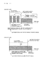
- FIG. 5 is a schematic diagram illustrating the operational states of “(a) hot water supply priority mode” and “(b) cooling priority mode” in the simultaneous cooling and hot water supply operation mode of the combined air-conditioning and hot water supply system 100 according to Embodiment 1.
- FIG. 6 illustrates switching between the cooling priority mode and the hot water supply priority mode in a cooling waste-heat recovery operation mode according to Embodiment 1.
- FIG. 7 illustrates the relationship between a priority operation determination threshold M, the outside air temperature, and time according to Embodiment 1.
- FIG. 8 illustrates the relationship between the priority operation determination threshold M, and the quantity of heat or the remaining amount of hot water in a hot water supply tank according to Embodiment 1.
- FIG. 9 is a refrigerant circuit diagram of a combined air-conditioning and hot water supply system 200 according to Embodiment 2.
- FIG. 10 illustrates details of operations of a four-way valve and the like with respect to the operation modes of the heat source unit 301 according to Embodiment 2.
- FIG. 11 is a schematic diagram of the operational states of the hot water supply priority mode and cooling priority mode in the simultaneous cooling and hot water supply operation mode of the combined air-cooling and hot water supply system 200 according to Embodiment 2.
- FIG. 12 illustrates variation of indoor suction temperature with time with respect to cooling thermo ON/OFF determination in the hot water supply priority mode of the simultaneous cooling and hot water supply operation mode of the combined air-cooling and hot water supply system 200 according to Embodiment 2.
- FIG. 1 is a refrigerant circuit diagram of a combined air-conditioning and hot water supply system 100 (cooling and hot water supply system) according to Embodiment 1.
- FIG. 1 the relative sizes of various components may differ from the actual ones.
- the units of the symbols are written inside [ ]. Dimensionless quantities (no units) will be represented as [-].
- FIG. 2 is a schematic diagram illustrating the flow of water from a hot water supply unit 304 to a hot water supply tank 305 in the combined air-conditioning and hot water supply system 100 .
- Broken line arrows 401 , 402 each indicate the flow direction of water.
- FIG. 3 is a schematic diagram illustrating various sensors, a measuring section 101 , a computing section 102 , and a control section 103 of the combined air-conditioning and hot water supply system 100 .
- FIGS. 1 to 3 the configuration of the combined air-conditioning and hot water supply system 100 will be described with reference to FIGS. 1 to 3 .
- the combined air-conditioning and hot water supply system 100 is a three-pipe multi-system combined air-conditioning and hot water supply system that can simultaneously handle a selected cooling operation or heating operation in a use unit and a hot water supply operation in a hot water supply unit, by carrying out a vapor compression refrigeration cycle operation.
- the combined air-conditioning and hot water supply system 100 executes a hot water supply operation in the hot water supply unit when a cooling operation is being performed, thereby enabling recovery of waste heat generated in the cooling operation.
- the combined air-conditioning and hot water supply system 100 is highly efficient, and can prevent running out of hot water by ensuring that it does not take a long time to complete hot water supply.
- the combined air-conditioning and hot water supply system 100 has a heat source unit 301 , a branch unit 302 , a use unit 303 , the hot water supply unit 304 , and the hot water supply tank 305 .
- the heat source unit 301 and the branch unit 302 are connected via a liquid extension pipe 6 that is a refrigerant pipe, and a gas extension pipe 12 that is a refrigerant pipe.
- One side of the hot water supply unit 304 is connected to the heat source unit 301 via a hot water supply gas extension pipe 15 that is a refrigerant pipe, and the other side is connected to the branch unit via a hot water supply liquid pipe 18 that is a refrigerant pipe.
- the use unit 303 and the branch unit 302 are connected via an indoor gas pipe 11 that is a refrigerant pipe, and an indoor liquid pipe 8 that is a refrigerant pipe.
- the hot water supply tank 305 and the hot water supply unit 304 are connected by an upstream water pipe 20 that is a water pipe, and a downstream water pipe 21 that is a water pipe.
- Embodiment 1 is directed to a case where a single heat source unit 1 is connected with a single use unit, a single hot water supply unit, and a single hot water supply tank, the present invention is not limited to this case.
- the numbers of these components may be more than or equal to, or less than or equal to those illustrated in the drawings.
- the refrigerant used in the combined air-conditioning and hot water supply system 100 is, for example, a HFC (hydrofluorocarbon) refrigerant such as R410A, R407C, or R404A, a HCFC (hydrochlorofluorocarbon) refrigerant such as R22 or R134a, or a natural refrigerant such as carbon hydride, helium, or carbon dioxide.
- the combined air-conditioning and hot water supply system 100 includes a system control device 110 as illustrated in FIG. 1 .
- the system control device 110 includes the measuring section 101 , the computing section 102 , the control section 103 , a clock section 104 , and a storing section 105 . While the system control device 110 is arranged in the heat source unit 301 in FIG. 1 , this is merely an example. The location where the system control device 110 is arranged is not limited.
- the operation mode of the heat source unit 301 is determined in accordance with the ratio between the hot water supply load in the connected hot water supply unit 304 and the cooling load or heating load in the connected use unit 303 .
- the combined air-conditioning and hot water supply system 100 is capable of executing three operation modes described below (a cooling operation mode, a simultaneous heating and hot water supply operation mode, and a simultaneous cooling and hot water supply operation mode).
- the cooling operation mode is the operation mode of the heat source unit 301 when there is no hot water supply request signal (described later) and the use unit 303 executes a cooling operation.
- the simultaneous heating and hot water supply operation mode is the operation mode of the heat source unit 301 when executing a simultaneous operation of a heating operation by the use unit 303 and a hot water supply operation by the hot water supply unit 304 .
- the simultaneous cooling and hot water supply operation mode is the operation mode of the heat source unit 301 when executing a simultaneous operation of a cooling operation by the use unit 303 and a hot water supply operation by the hot water supply unit 304 .
- the use unit 303 is connected to the heat source unit 301 via the branch unit 302 .
- the use unit 303 is installed in a location that allows the use unit 303 to blow conditioned air to an air-conditioned area (e.g. concealed or suspended on the ceiling inside a building, or hung on the wall surface).
- the use unit 303 is connected to the heat source unit 301 via the branch unit 302 , the liquid extension pipe 6 , and the gas extension pipe 12 , and constitutes a part of the refrigerant circuit.
- the use unit 303 includes an indoor-side refrigerant circuit that constitutes a part of the refrigerant circuit.
- This indoor-side refrigerant circuit is configured by an indoor heat exchanger 9 (second heat exchanger) that serves as a use-side heat exchanger.
- the use unit 303 is provided with an indoor air-sending device 10 for supplying conditioned air that has exchanged heat with the refrigerant passing through the indoor heat exchanger 9 to an air-conditioned area such as an indoor area.
- the indoor heat exchanger 9 can be configured by, for example, a cross-fin type fin-and-tube heat exchanger including a heat-transfer tube and a number of fins. Also, the indoor heat exchanger 9 may be configured by a micro-channel heat exchanger, a shell-and-tube heat exchanger, a heat-pipe heat exchanger, or a double-pipe heat changer.
- the indoor heat exchanger 9 When the use unit 303 executes the cooling operation mode and the simultaneous cooling and hot water supply operation mode, the indoor heat exchanger 9 functions as an evaporator of the refrigerant to cool the air in the air-conditioned area, and when the use unit 303 executes the simultaneous heating and hot water supply mode, the indoor heat exchanger 9 functions as a condenser (radiator) of the refrigerant to heat the air in the air-conditioned area.
- the indoor air-sending device 10 has the function of causing indoor air to be sucked into the use unit 303 , and after making the indoor air exchange heat with the refrigerant in the indoor heat changer 9 , supplying the air to the air-conditioned area as conditioned air. That is, in the use unit 303 , heat can be exchanged between the indoor air taken in by the indoor air-sending device 10 , and the refrigerant flowing through the indoor heat exchanger 9 .
- the indoor air-sending device 10 is configured to be able to vary the flow rate of conditioned air supplied to the indoor heat exchanger 9 .
- the indoor air-sending device 10 includes a fan such as a centrifugal fan or a multi-blade fan, and a motor that drives this fan, for example, a DC fan motor.
- the use unit 303 is provided with various sensors described below:
- an indoor liquid temperature sensor 206 that is provided on the liquid side of the indoor heat exchanger 9 , and detects the temperature of a liquid refrigerant
- an indoor gas temperature sensor 207 that is provided on the gas side of the indoor heat exchanger 9 , and detects the temperature of a gas refrigerant
- an indoor suction temperature sensor 208 that is provided on the suction port side of the indoor air of the use unit 303 , and detects the temperature of the indoor air entering the unit.
- the operation of the indoor air-sending device 10 is controlled by the control section 103 that functions as normal operation control means for performing normal operation of the use unit 303 including the cooling operation mode and the heating operation mode.
- the hot water supply unit 304 is connected to the heat source unit 301 via the branch unit 302 . As illustrated in FIG. 2 , the hot water supply unit 304 has the function of supplying hot water to the hot water supply tank 305 that is installed outside a building, for example, and heating and boiling up the water in the hot water supply tank 305 . Also, one side of the hot water supply unit 304 is connected to the heat source unit 301 via the hot water supply gas extension pipe 15 , and the other side is connected to the branch unit 302 via the hot water supply liquid pipe 18 .
- the hot water supply unit 304 constitutes a part of the refrigerant circuit in the combined air-conditioning and hot water supply system 100 .
- the hot water supply unit 304 includes a hot water supply-side refrigerant circuit that constitutes a part of the refrigerant circuit.
- This hot water supply-side refrigerant circuit has a plate water-heat exchanger 16 (water-heat exchanger) as its functional constituent.
- the hot water supply unit 304 is provided with a water supply pump 17 for supplying hot water that has exchanged heat with the refrigerant in the plate water-heat exchanger 16 to the hot water supply tank or the like.
- the plate water-heat exchanger 16 functions as a condenser (or radiator) of the refrigerant, and heats water that is supplied by the water supply pump 17 .
- the water supply pump 17 has the function of supplying water into the hot water supply unit 304 , causing the water to exchange heat in the plate water-heat exchanger 16 and turn into hot water, and thereafter supplying the hot water into the hot water supply tank 305 for heat exchange with the water in the hot water supply tank 305 .
- the hot water supply unit 304 heat can be exchanged between the water supplied from the water supply pump 17 and the refrigerant flowing through the plate water-heat exchanger 16 , and also heat can be exchanged between the water supplied from the water supply pump 17 and the water in the hot water supply tank 305 .
- the hot water supply unit 304 is configured to be able to vary the flow rate of water supplied to the plate water-heat exchanger 16 .
- the hot water supply unit 304 is provided with various sensors described below:
- a hot water supply liquid temperature sensor 209 that is provided on the liquid side of the plate water-heat exchanger 16 , and detects the temperature of a liquid refrigerant
- an inlet water temperature sensor 210 that is provided on the water inlet side of the hot water supply unit 304 , and detects the temperature of water entering the unit;
- an outlet water temperature sensor 211 that is provided on the water outlet side of the hot water supply unit 304 , and detects the temperature of water exiting the unit.
- the operation of the water supply pump 17 is controlled by the control section 103 that functions as normal operation control means for performing normal operation of the hot water supply unit 304 including the hot water supply operation mode.
- the hot water supply tank is installed outside a building, for example, and has the function of storing hot water boiled up by the hot water supply unit 304 .
- One side of the hot water supply tank 305 is connected to the hot water supply unit 304 via the upstream water pipe 20 , and the other side is connected to the hot water supply unit 304 via the downstream water pipe 21 .
- the hot water supply tank 305 constitutes a part of a water circuit 304 - 1 in the combined air-conditioning and hot water supply system 100 . That is, as illustrated in FIG. 2 , the upstream water pipe 20 , the downstream water pipe 21 , and the water supply pump 17 constitute the water circuit 304 - 1 in which the water to be heated by the plate water-heat exchanger 16 circulates.
- the hot water supply tank 305 is of an always-full type. As the user consumes water, hot water is released from the top of the tank, and city water is supplied from the bottom of the tank in accordance with the amount of released hot water.
- the water fed by the water supply pump 17 in the hot water supply unit 304 is heated by the refrigerant in the plate water-heat exchanger 16 and turns into hot water, and enters the hot water supply tank 305 via the upstream water pipe 20 .
- the hot water that has entered the hot water supply tank 305 exchanges heat with the water in the tank and turns into cold water.
- the cold water enters the hot water supply unit 304 again via the downstream water pipe 21 .
- the cold water turns into hot water in the plate water-heat exchanger 16 .
- hot water is boiled up in the hot water supply tank 305 . While hot water is boiled up indirectly according to the specifications in FIG. 2 , alternatively, the specifications may be such that hot water in the hot water supply tank 305 is fed to the hot water supply unit 304 and heated, thereby directly boiling up hot water.
- the hot water supply tank 305 is provided with various sensors described below:
- a first hot water supply tank water temperature sensor 212 that is provided on an upper side surface of the hot water supply tank 305 , and detects hot water supply temperature in an upper portion of the tank;
- a water supply temperature sensor 216 that detects the temperature of water supplied from the bottom of the hot water supply tank 305 .
- the heat source unit 301 is installed outside a building, for example.
- the heat source unit 301 is connected to the use unit 303 via the liquid extension pipe 6 , the gas extension pipe 12 , and the branch unit 302 .
- the heat source unit 301 is connected to the hot water supply unit 304 via the hot water supply gas extension pipe 15 , the liquid extension pipe 6 , and the branch unit 302 .
- the heat source unit 301 constitutes a part of the refrigerant circuit in the combined air-conditioning and hot water supply system 100 .
- the heat source unit 301 includes an outdoor-side refrigerant circuit that constitutes a part of the refrigerant circuit.
- This outdoor-side refrigerant circuit has, as its constituent devices, a compressor 1 that compresses the refrigerant, two four-way valves (a first four-way valve 2 and a second four-way valve 13 ) for switching the direction of flow of the refrigerant in accordance with the outdoor operation mode, an outdoor heat exchanger 3 (a first heat exchanger) serving as a heat source side heat exchanger, and an accumulator 14 for storing excess refrigerant.
- the heat source unit 301 includes an outdoor air-sending device 4 for supplying air to the outdoor heat exchanger 3 , and an outdoor pressure-reducing mechanism (heat source-side pressure-reducing mechanism) 5 for controlling the flow rate of the refrigerant to be distributed.
- an outdoor air-sending device 4 for supplying air to the outdoor heat exchanger 3
- an outdoor pressure-reducing mechanism (heat source-side pressure-reducing mechanism) 5 for controlling the flow rate of the refrigerant to be distributed.
- the compressor 1 sucks a refrigerant, and compresses the refrigerant into a high-temperature high-pressure state.
- the compressor 1 that is equipped in Embodiment 1 is capable of varying its operation capacity, and is configured by, for example, a positive displacement compressor that is driven by a motor (not illustrated) controlled by an inverter. While Embodiment 1 is directed to a case where there is only one compressor 1 , the present invention is not limited to this. Depending on the connected number of use units 303 and hot water supply units 304 , or the like, two or more compressors 1 may be connected in parallel.
- the discharge-side pipe connected to the compressor 1 is branched midway such that one side is connected to the gas extension pipe 12 via the second four-way valve 13 , and the other side is connected to the hot water supply gas extension pipe 15 via the first four-way valve 2 .
- the first four-way valve 2 and the second four-way valve 13 each function as a flow switching device that switches the direction of flow of the refrigerant in accordance with the operation mode of the heat source unit 301 .
- FIG. 4 illustrates details of operations of the four-way valves with respect to the operation modes.
- the “solid line” and “broken line” indicated in FIG. 4 refer to the “solid line” and “broken line” illustrated in FIG. 1 that represents the switching states of the first four-way valve 2 and second four-way valve 13 , respectively.
- the first four-way valve 2 is switched to the “solid line” in a cooling only operation mode. That is, in the cooling only operation mode, in order to make the outdoor heat exchanger 3 function as a condenser for the refrigerant that is compressed in the compressor 1 , the first four-way valve 2 is switched so as to connect the discharge side of the compressor 1 to the gas side of the outdoor heat exchanger 3 . Also, the first four-way valve 2 is switched to the “broken line” in the simultaneous heating and hot water supply operation mode or simultaneous cooling and hot water supply operation mode.
- the first four-way valve 2 is switched so as to connect the discharge side of the compressor 1 to the gas side of the plate water-heat exchanger 16 , and connect the suction side of the compressor 1 to the gas side of the outdoor heat exchanger 3 .
- the second four-way valve 13 is switched to the “solid line” in the cooling only operation mode or simultaneous cooling and hot water supply operation mode. That is, in the cooling only operation mode or simultaneous cooling and hot water supply operation mode, in order to make the indoor heat exchanger 9 function as an evaporator for the refrigerant that is compressed in the compressor 1 , the second four-way valve 13 is switched so as to connect the suction side of the compressor 1 to the gas side of the indoor heat exchanger 9 . Also, the second four-way valve 13 is switched to the “broken line” in the simultaneous heating and hot water supply operation mode.
- the second four-way valve 13 is switched so as to connect the discharge side of the compressor 1 to the gas side of the indoor heat exchanger 9 .
- the gas side of the outdoor heat exchanger 3 is connected to the first four-way valve 2 , and the liquid side is connected to an outdoor pressure-reducing mechanism 5 .
- the outdoor heat exchanger 3 can be configured by, for example, a cross-fin type fin-and-tube heat exchanger including a heat-transfer tube and a number of fins. Also, the outdoor heat exchanger 3 may be configured as a micro-channel heat exchanger, a shell-and-tube heat exchanger, a heat-pipe heat exchanger, or a double-pipe heat changer.
- the outdoor heat exchanger 3 functions as a condenser for the refrigerant to heat the refrigerant in the cooling only operation mode or simultaneous cooling and hot water supply operation mode, and functions as an evaporator for the refrigerant to cool the refrigerant in the simultaneous heating and hot water supply operation mode.
- the outdoor air-sending device 4 has the function of sucking the outdoor air into the heat source unit 301 , causing the outdoor air to exchange heat in the outdoor heat exchanger 3 , and thereafter emitting the air outdoors. That is, in the heat source unit 301 , heat can be exchanged between the outside air taken in by the outdoor air-sending device 4 , and the refrigerant flowing through the outdoor heat exchanger 3 .
- the outdoor air-sending device 4 is configured to be able to vary the flow rate of air supplied to the outdoor heat exchanger 3 .
- the outdoor air-sending device 4 includes a fan such as a propeller fan, and a motor that drives this fan, for example, a DC fan motor.
- the accumulator 14 is provided on the suction side of the compressor 1 .
- the accumulator 14 has the function of storing a liquid refrigerant to prevent liquid backflow to the compressor 1 when an abnormality occurs in the combined air-conditioning and hot water supply system 100 or during the transient response of the operational state caused by a change in operation control.
- the heat source unit 301 is provided with various sensors described below:
- a high-pressure pressure sensor 201 (high-pressure detecting device) that is provided on the discharge side of the compressor 1 , and detects a high-pressure side pressure;
- a discharge temperature sensor 202 that is provided on the discharge side of the compressor 1 , and detects a discharge temperature
- an outdoor gas temperature sensor 203 that is provided on the gas side of the outdoor heat exchanger 3 , and detects a gas refrigerant temperature
- an outdoor liquid temperature sensor 204 that is provided on the liquid side of the outdoor heat exchanger 3 , and detects the temperature of a liquid refrigerant
- an outside air temperature sensor 205 that is provided on the suction port side of the outside air of the heat source unit 301 , and detects the temperature of the outside air entering the unit.
- the operations of the compressor 1 , first four-way valve 2 , outdoor air-sending device 4 , outdoor pressure-reducing mechanism 5 , and second four-way valve 13 are controlled by the control section 103 that functions as normal operation control means for performing normal operation including the cooling operation mode, the simultaneous heating and hot water supply operation mode, and the simultaneous cooling and hot water supply operation mode.
- the branch unit 302 is installed inside a building, for example.
- the branch unit 302 is connected to the heat source unit 301 via the liquid extension pipe 6 and the gas extension pipe 12 , is connected to the use unit 303 via the indoor liquid pipe 8 and the indoor gas pipe 11 , and is connected to the hot water supply unit 304 via the hot water supply liquid pipe 18 .
- the branch unit 302 constitutes a part of the refrigerant circuit in the combined air-conditioning and hot water supply system 100 .
- the branch unit 302 has the function of controlling the flow of the refrigerant in accordance with the operation that is being required in each of the use unit 303 and the hot water supply unit 304 .
- the branch unit 302 includes a branch refrigerant circuit that constitutes a part of the refrigerant circuit.
- This branch refrigerant circuit has, as its constituent devices, an indoor pressure-reducing mechanism (use-side pressure-reducing mechanism) 7 for controlling the flow rate of the refrigerant to be distributed, and a hot water supply pressure-reducing mechanism 19 for controlling the flow rate of the refrigerant to be distributed.
- the indoor pressure-reducing mechanism 7 is provided in the indoor liquid pipe 8 .
- the hot water supply pressure-reducing mechanism 19 is provided in the hot water supply liquid pipe 18 within the branch unit 302 .
- the indoor pressure-reducing mechanism 7 functions as a pressure reducing valve or an expansion valve. In the cooling operation mode or the simultaneous cooling and hot water supply operation mode, the indoor pressure-reducing mechanism 7 reduces the pressure of the refrigerant flowing through the liquid extension pipe 6 to thereby cause the refrigerant to expand, and in the simultaneous heating and hot water supply operation mode, the indoor pressure-reducing mechanism 7 reduces the pressure of the refrigerant flowing through the indoor liquid pipe 8 to thereby cause the refrigerant to expand.
- the hot water supply pressure-reducing mechanism 19 functions as a pressure reducing valve or an expansion valve.
- the hot water supply pressure-reducing mechanism 19 reduces the pressure of the refrigerant flowing through the hot water supply liquid pipe 18 to thereby cause the refrigerant to expand.
- the indoor pressure-reducing mechanism 7 and the hot water supply pressure-reducing mechanism 19 are each preferably configured so that its opening degree can be variably controlled, for example, precision flow control means formed by an electronic expansion valve, or inexpensive refrigerant flow control means such as a capillary tube.
- the operation of the hot water supply pressure-reducing mechanism 19 is controlled by the control section 103 of the system control device 110 that functions as normal operation control means for performing normal operation of the hot water supply unit 304 including the hot water supply operation mode.
- the operation of the indoor pressure-reducing mechanism 7 is controlled by the control section 103 that functions as normal operation control means for performing normal operation of the use unit 303 including the cooling operation mode and the heating operation mode.
- various quantities detected by various temperature sensors and pressure sensors are inputted to the measuring section 101 , and processed in the computing section 102 . Then, on the basis of the processing results in the computing section 102 , the control section 103 controls the compressor 1 , the first four-way valve 2 , the outdoor air-sending device 4 , the outdoor pressure-reducing mechanism 5 , the indoor pressure-reducing mechanism 7 , the indoor air-sending device 10 , the second four-way valve 13 , the water supply pump 17 , and the hot water supply pressure-reducing mechanism 19 .
- the operation of the combined air-conditioning and hot water supply system 100 is controlled in a centralized manner by the system control device 110 including the measuring section 101 , the computing section 102 , and the control section 103 .
- the system control device 110 can be configured by a microcomputer, Calculation formulae in the following description of the embodiments are computed by the computing section 102 , and the control section 103 controls various devices such as the compressor 1 in accordance with the computation results.
- control section 103 executes various operation modes by controlling the driving frequency of the compressor 1 , switching of the first four-way valve 2 , the rotation speed (including ON/OFF) of the outdoor air-sending device 4 , the opening degree of the outdoor pressure-reducing mechanism 5 , the opening degree of the indoor pressure-reducing mechanism 7 , the rotation speed (including ON/OFF) of the indoor air-sending device 10 , switching of the second four-way valve 13 , the rotation speed (including ON/OFF) of the water supply pump 17 , and the opening degree of the hot water supply pressure-reducing mechanism 19 , on the basis of the operation mode inputted via a remote control (e.g.
- the measuring section 101 , the computing section 102 , and the control section 103 may be provided integrally, or may be provided separately. Also, the measuring section 101 , the computing section 102 , and the control section 103 may be provided in one of the units. Further, the measuring section 101 , the computing section 102 , and the control section 103 may be provided in each unit.
- the combined air-conditioning and hot water supply system 100 executes the cooling operation mode, the simultaneous heating and hot water supply operation mode, and the simultaneous cooling and hot water supply operation mode by controlling various devices equipped to the heat source unit 301 , the branch unit 302 , the use unit 303 , and the hot water supply unit 304 in accordance with each individual operating load required in the use unit 303 , and a hot water supply request signal requested to the hot water supply unit 304 .
- the simultaneous cooling and hot water supply operation mode allows waste heat generated in cooling to be used for hot water supply, thereby achieving high efficiency.
- FIG. 5 is a schematic diagram illustrating the operational states of “(a) hot water supply priority mode” and “(b) cooling priority mode” in the simultaneous cooling and hot water supply operation mode of the combined air-conditioning and hot water supply system 100 .
- “(a) hot water supply priority mode” the relationship between an absorbed heat quantity 601 in the outdoor heat exchanger 3 , and a cooling capacity 602 is illustrated.
- “(b) cooling priority mode” the cooling capacity 602 is illustrated. As illustrated in FIG.
- the simultaneous cooling and hot water supply operation mode further includes a “hot water supply priority mode” in which the operating frequency of the compressor 1 is controlled in accordance with a hot water supply request signal from the hot water supply unit 304 , and “cooling priority mode” in which the operating frequency of the compressor 1 is controlled in accordance with the cooling load in the use unit 303 .
- control section 103 operates in the cooling priority mode in a case where ⁇ T wm ⁇ M.
- the cooling priority mode is a mode in which the control section 103 controls the operating frequency of the compressor 1 in accordance with the indoor suction temperature detected by the measuring section 101 (detected by the measuring section 101 via the indoor suction temperature sensor 208 ), and the indoor set temperature of the use unit 303 that is held in advance (received by the control section 103 from a remote control or the use unit 303 , for example).
- control section 103 operates in the hot water supply priority mode in a case where ⁇ T wm ⁇ M.
- the hot water supply priority mode is a mode in which the control section 103 controls the operating frequency of the compressor 1 in accordance with the temperature differential between the set hot water supply temperature T wset , and the water temperature in the hot water supply tank 305 detected by the measuring section 101 (detected by the measuring section 101 via the first hot water supply tank water temperature sensors 212 to 215 , and the like).
- a hot water supply request signal is outputted by the hot water supply unit 304 when the temperature of water stored in the hot water supply tank 305 is below a set hot water supply temperature.
- the control section 103 makes the operating frequency of the compressor 1 higher to increase the hot water supply capacity.
- the cooling load is estimated from the temperature differential (indoor temperature differential) between the indoor suction temperature (suction air temperature) and the indoor set temperature (cooling set temperature), and the operating frequency is controlled by regarding that the larger the indoor temperature differential, the larger the cooling load.
- the control section 103 determines the operating frequency of the compressor 1 in accordance with a hot water supply request signal from the hot water supply unit 304 . For this reason, heat needs to be rejected in the outdoor heat exchanger 3 in order to make the cooling capacity and the cooling load equal.
- the control section 103 executes a cooling operation. In this operation, the operating frequency of the compressor 1 is raised to increase the hot water supply capacity, thereby completing hot water supply in a short time.
- the operating frequency of the compressor 1 is determined in accordance with the cooling load in the use unit 303 . Therefore, the cooling capacity and the cooling load become equal, and there is no need to remove heat in the outdoor heat exchanger 3 .
- the control section 103 executes a cooling operation. In this operation, the operating frequency of the compressor 1 is set lower than that in the hot water supply priority operation, and thus hot water supply can be performed with high efficiency. However, because the hot water supply capacity becomes smaller, it takes time to complete hot water supply.
- the specific operations of the cooling operation mode, simultaneous heating and hot water supply operation mode, and simultaneous cooling and hot water supply operation mode executed by the combined air-conditioning and hot water supply system 100 will be described.
- the operations of the four-way valves in individual operation modes are as illustrated in FIG. 4 .
- the use unit 303 is in the cooling operation mode.
- the first four-way valve 2 is in the state indicated by the solid line, that is, a state in which the discharge side of the compressor 1 is connected to the gas side of the outdoor heat exchanger 3 .
- the second four-way valve 13 is in the state indicated by the solid line, that is, a state in which the suction side of the compressor 1 is connected to the indoor heat exchanger 9 via the gas extension pipe 12 .
- the compressor 1 , the outdoor air-sending device 4 , and the indoor air-sending device 10 are activated. Then, a low-pressure gas refrigerant is sucked into the compressor 1 , where the refrigerant is compressed into a high-temperature high-pressure gas refrigerant. Thereafter, the high-temperature high-pressure gas refrigerant enters the outdoor heat exchanger 3 via the first four-way valve 2 , where the gas refrigerant is condensed by exchanging heat with the outdoor air supplied by the outdoor air-sending device 4 , and turns into a high-pressure gas refrigerant.
- the refrigerant flows to the outdoor pressure-reducing mechanism 5 , where its pressure is reduced. Thereafter, the refrigerant enters the branch unit 302 via the liquid extension pipe 6 . At this time, the outdoor pressure-reducing mechanism 5 is being controlled to the maximum opening degree.
- the refrigerant that has entered the branch unit 302 is reduced in pressure in the indoor pressure-reducing mechanism 7 , and turns into a two-phase gas-liquid refrigerant at low pressure, Thereafter, the refrigerant exits the branch unit 302 , and enters the use unit 303 via the indoor liquid pipe 8 .
- the refrigerant that has entered the use unit 303 enters the indoor heat exchanger 9 , and is evaporated into a low-pressure gas refrigerant by exchanging heat with the indoor air supplied by the indoor air-sending device 10 .
- the degree of subcooling of the refrigerant on the liquid side of the outdoor heat exchanger 3 is calculated by subtracting the temperature detected by the outdoor liquid temperature sensor 204 , from the saturation temperature (condensing temperature) computed from the pressure detected by the high-pressure pressure sensor 201 .
- the indoor pressure-reducing mechanism 7 controls the flow rate of the refrigerant flowing through the indoor heat exchanger 9 so that the degree of subcooling of the refrigerant on the liquid side of the outdoor heat exchanger 3 becomes a predetermined value. Consequently, the low-pressure gas refrigerant that has been evaporated in the outdoor heat exchanger 3 has a predetermined degree of subcooling. In this way, in the indoor heat exchanger 9 , refrigerant flows at a flow rate corresponding to the cooling load required in the conditioned space where the use unit 303 is installed.
- the refrigerant that has exited the indoor heat exchanger 9 exits the use unit 303 , and flows to the gas extension pipe 12 after passing through the indoor gas pipe 11 and the branch unit 302 .
- the refrigerant then passes through the accumulator 14 via the second four-way valve 13 , and is sucked into the compressor 1 again.
- the operating frequency of the compressor 1 is controlled by the control section 103 so that in the use unit 303 , there is no temperature difference between the indoor set temperature and the indoor suction temperature detected by the indoor suction temperature sensor 208 .
- the air flow of the outdoor air-sending device 4 is controlled by the control section 103 so that the condensing temperature becomes a predetermined value in accordance with the outside air temperature detected by the outside air temperature sensor 205 .
- the condensing temperature is the saturation temperature computed from the pressure detected by the high-pressure pressure sensor 201 .
- the use unit 303 is in the heating operation mode
- the hot water supply unit 304 is in the hot water supply operation mode.
- the first four-way valve 2 is in the state indicated by the broken line, that is, the discharge side of the compressor 1 is connected to the gas side of the plate water-heat exchanger 16
- the suction side of the compressor 1 is connected to the gas side of the outdoor heat exchanger 3
- the second four-way valve 13 is in the state indicated by the broken line, that is, the discharge side of the compressor 1 is connected to the gas side of the indoor heat exchanger 9 .
- the compressor 1 In this state of the refrigerant circuit, the compressor 1 , the outdoor air-sending device 4 , the indoor air-sending device 10 , and the water supply pump 17 are activated. Then, a low-pressure gas refrigerant is sucked into the compressor 1 , where the gas refrigerant is compressed into a high-temperature high-pressure gas refrigerant. Thereafter, the high-temperature high-pressure gas refrigerant is distributed so as to flow through the first four-way valve 2 or the second four-way valve 13 .
- the refrigerant that has entered the first four-way valve 2 exits the heat source unit 301 , and enters the hot water supply unit 304 via the hot water supply gas extension pipe 15 .
- the refrigerant that has entered the hot water supply unit 304 enters the plate water-heat exchanger 16 , where the refrigerant is condensed by exchanging heat with the water supplied by the water supply pump 17 and turns into a high-pressure liquid refrigerant, and exits the plate water-heat exchanger 16 .
- the refrigerant After the refrigerant that has heated the water in the plate water-heat exchanger 16 exits the hot water supply unit 304 , the refrigerant enters the branch unit 302 via the hot water supply liquid pipe 18 , and is reduced in pressure by the hot water supply pressure-reducing mechanism 19 and turns into a two-phase gas-liquid refrigerant at low pressure. Thereafter, the refrigerant joins the refrigerant that has flown through the indoor pressure-reducing mechanism 7 , and exits the branch unit 302 .
- the hot water supply pressure-reducing mechanism 19 is controlled by the control section 103 to such an opening degree that the degree of subcooling on the liquid side of the plate water-heat exchanger 16 becomes a predetermined value.
- the degree of subcooling on the liquid side of the plate water-heat exchanger 16 is calculated by computing the saturation temperature (condensing temperature) from the pressure detected by the high-pressure pressure sensor 201 , and subtracting the temperature detected by the hot water supply liquid temperature sensor 209 from the saturation temperature.
- the hot water supply pressure-reducing mechanism 19 controls the flow rate of refrigerant flowing through the plate water-heat exchanger 16 so that the degree of subcooling of the refrigerant on the liquid side of the plate water-heat exchanger 16 becomes a predetermined value
- the high-pressure liquid refrigerant that has been condensed in the plate water-heat exchanger 16 has a predetermined degree of subcooling.
- refrigerant flows at a flow rate corresponding to the hot water supply request requested in accordance with the use condition of hot water in the facility where the hot water supply unit 304 is installed.
- the refrigerant that has entered the second four-way valve 13 exits the heat source unit 301 , and flows to the branch unit 302 via the gas extension pipe 12 . Thereafter, the refrigerant enters the use unit 303 via the indoor gas pipe 11 .
- the refrigerant that has entered the use unit 303 enters the indoor heat exchanger 9 , where the refrigerant is condensed by exchanging heat with the indoor air supplied by the indoor air-sending device 10 and turns into a high-pressure liquid refrigerant, and exits the indoor heat exchanger 9 .
- the refrigerant that has heated the indoor air in the indoor heat exchanger 9 exits the use unit 303 , and enters the branch unit 302 via the indoor liquid pipe 8 .
- the refrigerant is then reduced in pressure by the indoor pressure-reducing mechanism 7 , and turns into a two-phase gas-liquid or liquid-phase refrigerant at low pressure. Thereafter, the refrigerant joins the refrigerant that has flown through the hot water supply pressure-reducing mechanism 19 , and exits the branch unit 302 .
- the indoor pressure-reducing mechanism 7 is controlled by the control section 103 to such an opening degree that the degree of subcooling on the liquid side of the indoor heat exchanger 9 becomes a predetermined value.
- the degree of subcooling on the liquid side of the indoor heat exchanger 9 is calculated by computing the saturation temperature (condensing temperature) from the pressure detected by the high-pressure pressure sensor 201 , and subtracting the temperature detected by the indoor liquid temperature sensor 206 from the saturation temperature. That is, the indoor pressure-reducing mechanism 7 is controlled by the control section 103 to such an opening degree that the degree of subcooling of the refrigerant on the liquid side of the indoor heat exchanger 9 becomes a predetermined value.
- the indoor pressure-reducing mechanism 7 controls the flow rate of refrigerant flowing through the indoor heat exchanger 9 so that the degree of subcooling of the refrigerant on the liquid side of the indoor heat exchanger 9 becomes a predetermined value
- the high-pressure liquid refrigerant that has been condensed in the indoor heat exchanger 9 has a predetermined degree of subcooling. Consequently, in the indoor heat exchanger 9 , refrigerant flows at a flow rate corresponding to the heating load required in the conditioned space where the use unit 303 is installed.
- the refrigerant that has exited the branch unit 302 enters the heat source unit 301 via the liquid extension pipe 6 , and after passing through the outdoor pressure-reducing mechanism 5 , the refrigerant enters the outdoor heat exchanger 3 .
- the opening degree of the outdoor pressure-reducing mechanism 5 is being controlled to the full opening.
- the refrigerant that has entered the outdoor pressure-reducing mechanism 5 is evaporated by exchanging heat with the outside air supplied by the outdoor air-sending device 4 , and turns into a low-pressure gas refrigerant. After exiting the outdoor heat exchanger 3 , this refrigerant passes through the accumulator 14 via the first four-way valve 2 , and is thereafter sucked into the compressor 1 again.
- the operating frequency of the compressor 1 is controlled by the control section 103 from a hot water supply request signal detected by the hot water supply tank. Also, the air flow of the outdoor air-sending device 4 is controlled by the control section 103 so that the evaporating temperature becomes a predetermined value in accordance with the outside air temperature detected by the outside air temperature sensor 205 .
- the evaporating temperature is calculated from the temperature detected by the outdoor liquid temperature sensor 204 .
- the use unit 303 is in the cooling operation mode
- the hot water supply unit 304 is in the hot water supply operation mode.
- the first four-way valve 2 is in the state indicated by the broken line, that is, the discharge side of the compressor 1 is connected to the plate water-heat exchanger 16 via the hot water supply gas extension pipe 15
- the suction side of the compressor 1 is connected to the gas side of the outdoor heat exchanger 3 .
- the second four-way valve 13 is in the state indicated by the broken line, that is, the suction side of the compressor 1 is connected to the indoor heat exchanger 9 via the gas extension pipe 12 .
- the compressor 1 when the outdoor air-sending device 4 , the indoor air-sending device 10 , and the water supply pump 17 are activated, a low-pressure gas refrigerant is sucked into the compressor 1 , where the gas refrigerant is compressed into a high-temperature high-pressure gas refrigerant. Thereafter, the high-temperature high-pressure gas refrigerant enters the first four-way valve 2 .
- the refrigerant that has entered the first four-way valve 2 exits the heat source unit 301 , and enters the hot water supply unit 304 via the hot water supply gas extension pipe 15 .
- the refrigerant that has entered the hot water supply unit 304 enters the plate water-heat exchanger 16 , where the refrigerant is condensed by exchanging heat with the water supplied by the water supply pump 17 and turns into a high-pressure liquid refrigerant, and exits the plate water-heat exchanger 16 .
- the refrigerant that has heated the water in the plate water-heat exchanger 16 exits the hot water supply unit 304 , and enters the branch unit 302 via the hot water supply liquid pipe 18 .
- the refrigerant that has entered the branch unit 302 is reduced in pressure by the hot water supply pressure-reducing mechanism 19 , and turns into a two-phase gas-liquid or liquid-phase refrigerant at intermediate pressure.
- the hot water supply pressure-reducing mechanism 19 is controlled to the maximum opening.
- the refrigerant is divided into a refrigerant that enters the liquid extension pipe 6 , and a refrigerant that enters the indoor pressure-reducing mechanism 7 .
- the refrigerant that has entered the indoor pressure-reducing mechanism 7 is reduced in pressure into a two-phase gas-liquid state at low pressure, and enters the use unit 303 via the indoor liquid pipe 8 .
- the refrigerant that has entered the use unit 303 enters the indoor heat exchanger 9 , where the refrigerant is evaporated by exchanging heat with the indoor air supplied by the indoor air-sending device 10 and turns into a low-pressure gas refrigerant.
- the indoor pressure-reducing mechanism 7 is controlled by the control section 103 to such an opening degree that the degree of subcooling of the refrigerant on the liquid side of the plate water-heat exchanger 16 becomes a predetermined value.
- the method of calculating this degree of subcooling is as previously described with reference to the cooling operation mode.
- the refrigerant that has flown through the indoor heat exchanger 9 thereafter exits the use unit 303 , and enters the heat source unit 301 via the indoor gas pipe 11 , the branch unit 302 , and the gas extension pipe 12 .
- the refrigerant that has entered the heat source unit 301 passes through the second four-way valve 13 , and thereafter joins the refrigerant that has passed through the indoor heat exchanger 3 .
- the refrigerant that has entered the liquid extension pipe 6 thereafter enters the heat source unit 301 , and after being reduced in pressure into a two-phase gas-liquid refrigerant at low pressure by the heat source-side pressure-reducing mechanism 5 , the refrigerant enters the outdoor heat exchanger 3 , where the refrigerant is evaporated by exchanging heat with the outdoor air supplied by the outdoor air-sending device 4 . Thereafter, the refrigerant passes through the first four-way valve 2 , and joins the refrigerant that has passed through the indoor heat exchanger 9 . Thereafter, the refrigerant passes through the accumulator 14 and is sucked into the compressor 1 again.
- the operating frequency of the compressor 1 is controlled by the control section 103 in accordance with a hot water supply request from the hot water supply unit 304 . Therefore, in order to make the cooling capacity equal to the cooling load in the use unit 303 , heat needs to be removed in the outdoor heat exchanger 3 .
- the opening degree of the outdoor pressure-reducing mechanism 5 is controlled by the control section 103 so that the degree of superheat on the gas side of the outdoor heat exchanger 3 becomes a predetermined value.
- the degree of superheat on the gas side of the outdoor heat exchanger 3 is calculated by subtracting the temperature detected by the outdoor liquid temperature sensor 204 from the temperature detected by the outdoor gas temperature sensor 203 .
- the air flow of the outdoor air-sending device 4 is controlled by the control section 103 so that in the use unit 303 , there is no temperature difference between the indoor set temperature and the temperature detected by the indoor suction temperature sensor 208 .
- the operating frequency of the compressor 1 is determined by the temperature differential between the indoor suction temperature and the indoor set temperature in accordance with the cooling load in the use unit 303 .
- the operating frequency of the compressor 1 is determined by the temperature differential between the indoor suction temperature and the indoor set temperature in accordance with the cooling load in the use unit 303 .
- the opening degree of the outdoor pressure-reducing mechanism 5 is controlled to a small opening by the control section 103 , and the outdoor air-sending device 4 is controlled so as to be stopped by the control section 103 .
- hot water can be supplied with higher efficiency by performing the simultaneous cooling and hot water supply operation mode in cooling priority than in hot water supply priority, it takes time for hot water supply to be completed. For this reason, in a case where a large quantity of heat is required until completion of hot water supply, it is necessary to perform the simultaneous cooling and hot water supply operation mode in hot water supply priority in order to prevent running out of hot water. Also, it is considered that in a case where the inlet water temperature is low relative to the set hot water supply temperature, the water temperature in the hot water supply tank 305 is also low, and thus a large quantity of heat is required for hot water supply.
- the set hot water supply temperature T wset refers to the temperature of hot water that is set by the user with a remote control (not illustrated), the temperature of hot water in the hot water supply tank, or the like.
- FIG. 6 illustrates switching between the cooling priority mode and the hot water supply priority mode.
- the priority operation determination threshold M [° C.] is set as illustrated in FIG. 6 .
- the control section 103 operates in the cooling priority mode when the hot water supply temperature differential ⁇ T wm of Equation (1) above is lower than the priority operation determination threshold M [° C.], and operates in hot water supply priority when the hot water supply temperature differential ⁇ T wm is equal to or higher than the priority operation determination threshold M [° C.]. Since the hot water supply tank 305 is of an always-full type, the amount of water in the hot water supply tank 305 is always constant. Therefore, in this way, it is possible to appropriately estimate the quantity of heat required for hot water supply.
- the operation is performed in cooling priority, and in a case where a large quantity of heat is required, the operation is performed in hot water supply priority to prevent an increase in hot water supply time, thereby preventing running out of hot water.
- FIG. 7 illustrates the relationship between the priority operation determination threshold M, the outside air temperature, and time.
- the priority operation determination threshold M is set larger.
- a time schedule variation of amount of daily hot water usage with time
- the control section 103 sets the priority operation determination threshold M smaller at a time (time X) during high hot water usage periods in a day than at a time (time Y) during low hot water usage periods.
- the control section 103 sets the priority operation determination threshold M smaller during a time period in the time schedule in which the amount of hot water usage exceeds a predetermined amount than during a time period in which the amount of hot water usage does not exceed the predetermined amount.
- the time schedule of daily hot water usage is prepared by recording the amount of hot water usage into a memory within the microcomputer at intervals of every hour or more (e.g. every two hours) over a day or more days (e.g. one week), Also, the time schedule may be inputted by the user.
- FIG. 8 illustrates the relationship between the priority operation determination threshold M, and the quantity of heat or the remaining amount of hot water in the hot water supply tank.
- the priority operation determination threshold M [° C.] is set.
- the control section 103 receives input of a stored heat quantity stored in the hot water supply tank 305 from the computing section 102 (stored heat quantity computing section) that computes the stored heat quantity. Then, as illustrated in FIG. 8 , the larger the inputted stored heat quantity, the larger the control section 103 sets the priority operation determination threshold M.
- the remaining amount of hot water as illustrated in FIG.
- the control section 103 receives input of a stored heat quantity stored in the hot water supply tank 305 from the computing section 102 (stored heat quantity computing section) that computes the stored heat quantity, and as illustrated in FIG. 8 , the larger the inputted stored heat quantity, the larger the control section 103 sets the priority operation determination threshold M.
- This control makes it possible to prevent the hot water supply priority operation from being executed even through a large quantity of effective heat exists in the hot water supply tank, and eliminate loss of opportunities for executing the cooling priority operation mode, thereby achieving higher operation efficiency.
- the specific method of computing, by the computing section 102 , the quantity of heat and remaining amount of hot water in the hot water supply tank 305 is as described below.
- the computing section 102 computes the heat quantity Q TANK [KJ] in the hot water supply tank from Equation (2) below, by using the temperature sensors provided to the hot water supply tank 305 according to Embodiment 1:
- ⁇ w [g/m3] denotes the density of water
- V TANK, 1 [L] denotes the internal volume of the hot water supply tank from the top of the hot water supply tank 305 to the installation height of the first hot water supply tank water temperature sensor 212 ,
- V TANK, 2 [L] denotes the internal volume of the hot water supply tank from the top of the hot water supply tank 305 to the installation height of the second hot water supply tank water temperature sensor 213 ,
- V TANK, 3 [L] denotes the internal volume of the hot water supply tank from the top of the hot water supply tank 305 to the installation height of the third hot water supply tank water temperature sensor 214 , and
- V TANK, 4 [L] denotes the internal volume of the hot water supply tank from the top of the hot water supply tank 305 to the installation height of the fourth hot water supply tank water temperature sensor 215 .
- the internal volumes can be computed by determining the installation heights of the respective sensors in advance at the time of design.
- T TANK, 1 [° C.] denotes the detection temperature of the first hot water supply tank water temperature sensor 212 .
- T TANK, 2 [° C.] denotes the detection temperature of the second hot water supply tank water temperature sensor 213 ,
- T TANK, 3 [° C.] denotes the detection temperature of the third hot water supply tank water temperature sensor 214 .
- T TANK, 4 [° C.] denotes the detection temperature of the fourth hot water supply tank water temperature sensor 215 .
- T TANKWi [° C.] denotes the detection temperature of the water supply temperature sensor 216 .
- the computing section 102 computes the heat quantity Q TANK in the hot water supply tank 305 by setting T TANK, 1 , T TANK, 2 , T TANK, 3 , T TANK, 4 to T w, set , by regarding that the temperature of hot water in the hot water supply tank 305 has reached the hot water supply temperature T w, set . Then, in a case where the value of Q TANK computed from sensor information on the current temperature of the hot water supply tank 305 is equal to or less than half (predetermined heat quantity) of this computed value, the control section 103 sets the operation to the hot water supply priority operation mode irrespective of the hot water supply temperature differential ⁇ T wm .
- the control section 103 receives input of a stored heat quantity stored in the hot water supply tank 305 from the computing section 102 (stored heat quantity computing section) that computes the stored heat quantity.
- the control section 103 executes the hot water supply priority mode when the stored heat quantity inputted from the computing section 102 is smaller than a predetermined heat quantity. This control prevents running out of hot water.
- four temperature sensors are installed on the side surface of the tank in the hot water supply tank according to Embodiment 1, the number of temperature sensors is not limited to this. It is possible to compute the heat quantity in the hot water supply tank 305 with higher precision by installing more temperature sensors in the height direction of the tank.
- the computing section 102 can compute the remaining amount of hot water L w [L] as follows.
- T wu denotes the temperature [° C.] hot water used by the user.
- L w [L] becomes equal to or less than half of the capacity (predetermined capacity) of the hot water supply tank 305 , the operation is set to the hot water supply priority operation mode irrespective of the hot water supply temperature differential ⁇ T wm .
- control section 103 receives input of the remaining amount of hot water L w remaining in the hot water supply tank 305 from the computing section (remaining hot water amount computing section) that computes the remaining amount of hot water, and executes the hot water supply priority mode when the inputted remaining amount of hot water L w is less than a predetermined amount. This control prevents running out of hot water.
- the control section 103 measures the operating time of the cooling priority mode by the clock section 104 , and makes the operating frequency of the compressor 1 higher to thereby increase the hot water supply capacity when the operating time of the cooling priority mode becomes equal to or more than a predetermined time. At this time, the larger the hot water supply temperature differential ⁇ T wm , the higher the operating frequency of the compressor 1 is controlled.
- the control section 103 controls the operating frequency of the compressor 1 .
- the operation may be forcibly set to the hot water supply priority mode.
- the operation may be executed in the hot water supply priority mode to give priority to shortening of the hot water supply time.
- the coefficient of performance (COP) [-] of the cooling priority mode in cooling waste-heat recovery operation can be computed by the equation below from the sum of the cooling capacity of the use unit 303 and the hot water supply capacity of the hot water supply unit 304 with respect to the amount of input to the compressor 1 .
- W COMP the compressor input “kW”.
- the second term of the numerator is the cooling capacity, which is the difference between the hot water supply capacity Q w and the compressor input W COMP .
- G r denotes the circulation amount of refrigerant at the discharge of the compressor, and is determined from the saturation temperature (condensing temperature) of the pressure detected by the high-pressure pressure sensor 201 , the temperature (evaporating temperature) detected by the indoor liquid temperature sensor 206 , and the compressor frequency.
- h d [kJ/kg] denotes the specific enthalpy at the discharge of the compressor, and is computed from the pressure detected by the high-pressure pressure sensor 201 , and the temperature detected by the discharge temperature sensor 202 .
- h s [kJ/kg] denotes the specific enthalpy at the suction of the compressor, and since the circuit is an accumulator circuit, the degree of suction superheating is 0, and the specific enthalpy is computed from the indoor liquid temperature sensor 206 .
- Qw is computed by the equation below from the difference between the outlet and inlet temperatures of water supplied to the hot water supply unit 304 :
- Q w ⁇ w ⁇ C p,w ⁇ V w ⁇ ( T wo ⁇ T wi ) (6)
- ⁇ w [kg/m3] denotes the density of water
- V w [m3/s] denotes the flow rate of water
- T wo [° C.] denotes the water temperature at the outlet of the plate water-heat exchanger 16 .
- T wi denotes the water temperature at the inlet of the plate water-heat exchanger 16 .
- control section 103 can compute the coefficient of performance (COP) from the operational state.
- the control section 103 forcibly sets the operation to the hot water supply priority mode when COP becomes equal to or less than a predetermined value.
- the control section 103 receives input of the coefficient of performance (COP) of the cooling priority mode from the computing section (coefficient-of-performance computing section) that computes the coefficient of performance (COP) of the cooling priority mode, and when the inputted coefficient of performance (COP) is equal to or less than a predetermined value, the control section 103 switches the cooling priority mode that is being executed to the hot water supply priority mode.
- COP coefficient of performance
- the use unit 303 or a remote control for operating the use unit 303 may be provided with a display section that allows the operation of the combined air-conditioning and hot water supply system 100 or the heat source unit 301 to be recognized, so that the user can change the operation of the heat source unit 301 .
- an indication of the cooling priority mode or hot water supply priority mode is displayed on the display section. Then, when the user recognizes an abrupt increase in the consumption of hot water, the hot water supply priority mode is forcibly designated with the remote control (operating section), thereby preventing running out of hot water.
- cooling operation mode it is also preferable to display an indication of the cooling operation mode, the simultaneous heating and hot water supply operation mode, the simultaneous cooling and hot water supply operation mode, or the like so that the user can easily recognize the operational state.
- the use unit 303 includes a display section 303 - 1 and an operating section 303 - 2 .
- the display section 303 - 1 displays whether the current operation mode is the cooling priority mode or the hot water supply priority mode.
- the operating section 303 - 2 outputs a switch command signal that commands switching from the current priority mode displayed on the display section 303 - 1 to the other priority mode.
- the switch command signal outputted from the operating section 303 - 2 is inputted, and upon receiving input of the switch command signal, the control section 103 switches the current priority mode to the other priority mode.
- a switch command signal is outputted from a remote control that has a display section for displaying whether the current operation mode is the cooling priority mode or the hot water supply priority mode, and outputs the switch command signal that commands switching from the current priority mode displayed on the display section to the other priority mode.
- the control section 103 switches the current priority mode to the other priority mode.
- ⁇ T in Equation 7 calculated by the temperature differential between the condensing temperature CT [° C.] of the outdoor heat exchanger 3 and the set hot water supply temperature T wset [° C.] may be used instead of the temperature differential ⁇ T wm [° C.]. In this way, even if there is no inlet water temperature sensor 210 , ⁇ T in Equation 7 can be used to determine whether the operation is to be the cooling priority operation or the hot water supply priority operation on the basis of the priority operation determination threshold M.
- Embodiment 1 it is possible to provide the combined air-conditioning and hot water supply system 100 capable of recovering waste heat generated in cooling to the hot water supply operation, which is highly efficient and does not compromise indoor comfort, and does not require a long time for hot water supply to be completed, thereby preventing running out of hot water.
- Embodiment 2 will be described with reference to FIGS. 9 to 12 .
- FIG. 9 is a refrigerant circuit diagram illustrating the refrigerant circuit configuration of a combined air-conditioning and hot water supply system 200 according to Embodiment 2.
- the configuration and operation of the combined air-conditioning and hot water supply system 200 will be described with reference to FIG. 9 .
- the combined air-conditioning and hot water supply system 200 according to Embodiment 2 also includes the system control device 110 .
- the following description of Embodiment 2 mainly focuses on differences from Embodiment 1 described above, and portions having the same functions as those in Embodiment 1 are denoted by the same reference numerals and a description of those portions is omitted.
- the combined air-conditioning and hot water supply system 200 is a three-pipe multisystem combined air-conditioning and hot water supply system that can simultaneously handle a selected cooling operation or heating operation in the use unit 303 and a hot water supply operation in the hot water supply unit, by carrying out a vapor compression refrigeration cycle operation.
- the combined air-conditioning and hot water supply system 200 executes the hot water supply operation in the hot water supply unit when the cooling operation is being performed, thereby enabling recovery of waste heat generated in the cooling operation.
- the combined air-conditioning and hot water supply system 200 is highly efficient and does not compromise indoor comfort, and can prevent running out of hot water by ensuring that it does not take a long time to complete hot water supply.
- the combined air-conditioning and hot water supply system 200 includes the heat source unit 301 , the use unit 303 , the hot water supply unit 304 , and the hot water supply tank 305 . Since the combined air-conditioning and hot water supply system 200 according to Embodiment 2 is provided with a single use unit, with regard to the representation of the components related to the use unit 303 , alphabets following the corresponding numerals are not indicated.
- the heat source unit 301 and the use unit 303 are connected via the liquid extension pipe 6 that is a refrigerant pipe, and the gas extension pipe 12 that is a refrigerant pipe.
- the heat source unit 301 and the hot water supply unit 304 are connected by the hot water supply gas extension pipe 15 that is a refrigerant pipe, and a hot water supply liquid extension pipe 26 that is a refrigerant pipe.
- the hot water supply unit 304 and the hot water supply tank 305 are connected by the upstream water pipe 20 that is a water pipe, and the downstream water pipe 21 that is a water pipe.
- the configuration of the refrigerant circuit of each of the use unit 303 and the hot water supply unit 304 is the same as that of the combined air-conditioning and hot water supply system 100 according to Embodiment 1. Also, the configuration of the water circuit of the hot water supply tank 305 is the same as that of the combined air-conditioning and hot water supply system 100 according to Embodiment 1.
- the circuit configuration of the heat source unit 301 is such that the first four-way valve 2 , the second four-way valve 13 , and the accumulator 14 are removed from the combined air-conditioning and hot water supply system 100 according to Embodiment 1 , and an air-conditioning discharge solenoid valve 22 that controls the direction of flow of refrigerant, a hot water supply discharge solenoid valve 25 , a low-pressure equalizing solenoid valve 27 , a third three-way valve 23 that switches the direction of flow of refrigerant, and a receiver 24 for storing excess refrigerant are installed.
- the outdoor-side refrigerant circuit provided in the heat source unit 301 has the compressor 1 , the third four-way valve 23 , the outdoor heat exchanger 3 , the outdoor air-sending device 4 , the outdoor pressure-reducing mechanism 5 , the receiver 24 , the air-conditioning discharge solenoid valve 22 , the hot water supply discharge solenoid valve 25 , and the low-pressure equalizing solenoid valve 27 .
- the combined air-conditioning and hot water supply system 200 can execute three operation modes (a cooling operation mode, a simultaneous heating and hot water supply operation mode, and a simultaneous cooling and hot water supply operation mode).
- FIG. 10 illustrates details of operations of the four-way valve 23 and the like with respect to the operation modes of the heat source unit 301 of the combined air-conditioning and hot water supply system 200 .
- the operations of the four-way valve and solenoid valves in individual operation modes are as illustrated in FIG. 10 .
- the cooling and hot water supply operation mode includes a hot water supply priority mode that determines the operating frequency of the compressor 1 in accordance with a hot water supply request from the hot water supply unit 304 , and a cooling priority mode that determines the operating frequency of the compressor 1 in accordance with the cooling load in the use unit 303 .
- the third four-way valve 23 is in the state indicated by the solid line, that is, a state in which the discharge side of the compressor 1 is connected to the gas side of the outdoor heat exchanger 3 , and the suction side of the compressor 1 is connected to the gas side of the indoor heat exchanger 9 . Also, the air-conditioning discharge solenoid valve 22 is open, the hot water supply discharge solenoid valve 25 is closed, and the low-pressure equalizing solenoid valve 27 is closed. In this state of the refrigerant circuit, the control section 103 activates the compressor 1 , the outdoor air-sending device 4 , and the indoor air-sending device 10 .
- a low-pressure gas refrigerant is sucked into the compressor 1 , where the gas refrigerant is compressed into a high-temperature high-pressure gas refrigerant.
- the high-temperature high-pressure gas refrigerant enters the outdoor heat exchanger 3 via the third four-way valve 23 , where the gas refrigerant is condensed by exchanging heat with the outdoor air supplied by the outdoor air-sending device 4 , and turns into a low-pressure gas refrigerant.
- the refrigerant flows to the outdoor pressure-reducing mechanism 5 , where the refrigerant is reduced in pressure.
- the outdoor pressure-reducing mechanism 5 is controlled so that the degree of subcooling on the liquid side of the outdoor heat exchanger 3 becomes a predetermined value.
- the degree of subcooling on the liquid side of the outdoor heat exchanger 3 is calculated by subtracting the temperature detected by the outdoor liquid temperature sensor 204 , from the saturation temperature computed from the pressure detected by the high-pressure pressure sensor 201 .
- the refrigerant After exiting the outdoor pressure-reducing mechanism 5 , the refrigerant passes through the receiver 24 , is reduced in pressure in the indoor pressure-reducing mechanism 7 , and exits the heat source unit 301 . Then, the refrigerant enters the use unit 303 via the liquid extension pipe 6 , and enters the indoor heat exchanger 9 , where the refrigerant is evaporated by exchanging heat with the indoor air supplied from the indoor air-sending device 10 , and turns into a low-pressure gas refrigerant.
- the indoor pressure-reducing mechanism 7 is controlled so that the degree of superheat on the gas side of the indoor heat exchanger 9 becomes a predetermined value.
- the degree of superheat on the gas side of the indoor heat exchanger 9 is calculated by subtracting the temperature detected by the indoor liquid temperature sensor 206 , from the temperature detected by the indoor gas temperature sensor 207 .
- the refrigerant exits the use unit 303 , and enters the heat source unit 301 via the gas extension pipe 12 . Thereafter, the refrigerant passes through the third three-way valve 23 , and enters the compressor 1 again.
- the operating frequency of the compressor 1 is controlled by the control section 103 so that in the use unit 303 , the temperature difference between the indoor set temperature and the temperature detected by the indoor suction temperature sensor 208 becomes small. Also, the air flow of the outdoor air-sending device 4 is controlled by the control section 103 so that the condensing temperature becomes a predetermined value in accordance with the outside air temperature detected by the outside air temperature sensor 205 .
- the condensing temperature is the saturation temperature computed from the pressure detected by the high-pressure pressure sensor 201 .
- the third four-way valve 23 is in the state indicated by the broken line, that is, the discharge side of the compressor 1 is connected to the gas side of the indoor heat exchanger 9 , and the suction side of the compressor 1 is connected to the gas side of the outdoor heat exchanger 3 . Also, the air-conditioning discharge solenoid valve 22 is open, the hot water supply discharge solenoid valve 25 is open, and the low-pressure equalizing solenoid valve 27 is closed. In this state of the refrigerant circuit, the compressor 1 , the outdoor air-sending device 4 , the indoor air-sending device 10 , and the water supply pump 17 are activated.
- a low-pressure gas refrigerant is sucked into the compressor 1 , where the refrigerant is compressed into a high-temperature high-pressure gas refrigerant. Thereafter, the high-temperature high-pressure gas refrigerant is distributed so as to flow through the hot water supply discharge solenoid valve 25 or the air-conditioning discharge solenoid valve 22 .
- the refrigerant that has entered the hot water supply discharge solenoid valve 25 exits the heat source unit 301 , and enters the hot water supply unit 304 via the hot water supply gas extension pipe 15 .
- the refrigerant that has entered the hot water supply unit 304 enters the plate water-heat exchanger 16 , where the refrigerant is condensed by exchanging heat with the water supplied by the water supply pump 17 and turns into a high-pressure liquid refrigerant, and exits the plate water-heat exchanger 16 .
- the refrigerant After the refrigerant that has heated the water in the plate water-heat exchanger 16 exits the hot water supply unit 304 , the refrigerant enters the heat source unit 301 via the hot water supply liquid extension pipe 26 , and is reduced in pressure by the hot water supply pressure-reducing mechanism 19 . Thereafter, the refrigerant joins the refrigerant that has flown through the indoor pressure-reducing mechanism 7 .
- the hot water supply pressure-reducing mechanism 19 is controlled by the control section 103 to such an opening degree that the degree of subcooling on the liquid side of the plate water-heat exchanger 16 becomes a predetermined value.
- the degree of subcooling on the liquid side of the plate water-heat exchanger 16 is calculated by computing the saturation temperature (condensing temperature) from the pressure detected by the high-pressure pressure sensor 201 , and subtracting the temperature detected by the hot water supply liquid temperature sensor 209 from the saturation temperature.
- the refrigerant that has entered the air-conditioning discharge solenoid valve 22 passes through the third four-way valve 23 , the refrigerant exists the heat source unit 301 , and enters the use unit 303 via the gas extension pipe 12 .
- the refrigerant that has entered the use unit 303 enters the indoor heat exchanger 9 , where the refrigerant is condensed by exchanging heat with the indoor air supplied by the indoor air-sending device 10 and turns into a high-pressure liquid refrigerant, and exits the indoor heat exchanger 9 .
- the refrigerant that has heated the indoor air in the indoor heat exchanger 9 exits the use unit 303 , enters the heat source unit 301 via the liquid extension pipe 6 , and is reduced in pressure by the indoor pressure-reducing mechanism 7 . Thereafter, the refrigerant joins the refrigerant that has flown through the hot water supply pressure-reducing mechanism 19 .
- the indoor pressure-reducing mechanism 7 is controlled by the control section 103 to such an opening degree that the degree of subcooling of the refrigerant on the liquid side of the indoor heat exchanger 9 becomes a predetermined value.
- the degree of subcooling of the refrigerant on the liquid side of the indoor heat exchanger 9 is calculated by subtracting the temperature detected by the indoor liquid temperature sensor 206 , from the saturation temperature (condensing temperature) computed from the pressure detected by the high-pressure pressure sensor 201 .
- the joined refrigerant passes through the receiver 24 , is reduced in pressure by the outdoor pressure-reducing mechanism 5 , and enters the outdoor heat exchanger 2 .
- the opening degree of the outdoor pressure-reducing mechanism 5 is controlled so that the degree of superheat on the gas side of the outdoor heat exchanger 3 becomes a predetermined value.
- the degree of superheat on the gas side of the outdoor heat exchanger 3 is calculated by subtracting the temperature detected by the outdoor liquid temperature sensor 204 from the temperature detected by the outdoor gas temperature sensor 203 .
- the refrigerant that has entered the outdoor heat exchanger 3 is evaporated by exchanging heat with the indoor air supplied by the outdoor air-sending device 4 and turns into a low-pressure gas refrigerant. After exiting the outdoor heat exchanger 3 , this refrigerant is sucked into the compressor 1 again via the third four-way valve 23 .
- the operating frequency of the compressor 1 is controlled by the control section 103 from a hot water supply request signal detected by the hot water supply tank. Also, the air flow of the outdoor air-sending device 4 is controlled by the control section 103 so that the evaporating temperature becomes a predetermined value in accordance with the outside air temperature detected by the outside air temperature sensor 205 .
- the evaporating temperature is calculated from the temperature detected by the outdoor liquid temperature sensor 204 .
- the third four-way valve 23 is in the state indicated by the solid line, that is, the discharge side of the compressor 1 is connected to the gas side of the outdoor heat exchanger 3 , and the suction side of the compressor 1 is connected to the gas side of the indoor heat exchanger 9 . Also, the air-conditioning discharge solenoid valve 22 is closed, the hot water supply discharge solenoid valve 25 is open, and the low-pressure equalizing solenoid valve 27 is open.
- the refrigerant that has entered the hot water supply unit 304 enters the plate water-heat exchanger 16 , where the refrigerant is condensed by exchanging heat with the water supplied by the water supply pump 17 and turns into a high-pressure liquid refrigerant, and exits the plate water-heat exchanger 16 .
- the refrigerant that has heated the water in the plate water-heat exchanger 16 exits the hot water supply unit 304 , and enters the heat source unit 301 via the hot water supply liquid extension pipe 26 .
- the refrigerant that has entered the heat source unit 301 passes through the hot water supply pressure-reducing mechanism 19 that is fixed to the maximum opening, and thereafter, the refrigerant is divided into a refrigerant that enters the indoor pressure-reducing mechanism 7 , and a refrigerant that enters the receiver 24 .
- the refrigerant that has entered the indoor pressure-reducing mechanism 7 is reduced in pressure.
- the refrigerant exits the heat source unit 301 , and enters the use unit 303 via the liquid extension pipe 6 .
- the refrigerant then enters the indoor heat exchanger 9 , where the refrigerant is evaporated by exchanging heat with the indoor air supplied by the indoor air-sending device 10 and turns into a low-pressure gas refrigerant.
- the indoor pressure-reducing mechanism 7 is controlled so that the degree of superheat on the gas side of the indoor heat exchanger 9 becomes a predetermined value.
- the method of calculating this degree of superheat is the same as in the case of the cooling operation mode.
- the refrigerant that has flown through the indoor heat exchanger 9 thereafter exits the use unit 303 , and enters the heat source unit 301 via the gas extension pipe 12 .
- the refrigerant that has entered the heat source unit 301 passes through the third four-way valve 23 , and thereafter joins the refrigerant that has passed through the indoor heat exchanger 3 .
- the refrigerant that has entered the receiver 24 passes through the outdoor pressure-reducing mechanism 5 that is fixed to a small opening, where the pressure of the refrigerant is reduced to a low pressure. Thereafter, the refrigerant is heated by the outside air in the outdoor heat exchanger 3 , and turns into a low-pressure gas refrigerant. Thereafter, the refrigerant passes through the low-pressure equalizing solenoid valve 27 , and joins the refrigerant that has passed through the indoor heat exchanger 9 . After joining, the resulting refrigerant is sucked into the compressor 1 again.
- the low-pressure equalizing solenoid valve 27 Since the low-pressure equalizing solenoid valve 27 is installed in order to make the pressure in the outdoor heat exchanger 3 low, its bore diameter is small. Therefore, the low-pressure equalizing solenoid valve 27 is unable to remove excess heat of cooling. Therefore, the air flow of the outdoor air-sending device 4 is controlled to the minimum value required to cool the radiator plate, and the opening degree of the outdoor pressure-reducing mechanism 5 is controlled to a small opening.
- the operating frequency of the compressor 1 is controlled by the control section 103 on the basis of a hot water supply request from the hot water supply unit 304 . Also, in a case where the simultaneous cooling and hot water supply operation mode is the cooling priority mode, the operating frequency of the compressor 1 is determined from the temperature differential between the indoor suction temperature and the indoor set temperature in accordance with the cooling load in the use unit 303 .
- the small bore diameter of the low-pressure equalizing valve 27 makes it impossible to make a large amount of refrigerant flow to the outdoor heat exchanger 3 . Consequently, heat cannot be removed in the outdoor heat exchanger 3 , which means that waste heat generated in cooling is completely recovered for the hot water supply. Therefore, the operation according to the hot water supply priority mode differs from that in the case of the combined air-conditioning and hot water supply system 100 according to Embodiment 1.
- FIG. 11 is a schematic diagram of operations of the hot water supply priority mode and cooling priority mode in the simultaneous cooling and hot water supply operation of the combined air-cooling and hot water supply system 100 according to Embodiment 2.
- the hatching in FIG. 11 indicates a cooling capacity 602 .
- the simultaneous cooling and hot water supply operation mode is executed in the hot water supply priority mode, the operating frequency of the compressor 1 is determined in accordance with a hot water supply request signal from the hot water supply unit 304 , and thus the cooling capacity becomes larger than the cooling load. Therefore, when the cooling indoor temperature of the use unit 303 becomes lower than the indoor set temperature, the control section 103 turns the cooling thermo OFF, and executes the hot water supply operation.
- the control section 103 executes a control that sets the operation to hot water supply operation by closing the indoor pressure-reducing mechanism 7 , and by closing the low-pressure equalizing solenoid valve 27 and switching the four-way valve 23 to the state of the broken line.
- switching of the four-way valve 23 requires the presence of a differential pressure between upstream and downstream of the four-way valve 23 .
- the pressure is low both upstream and downstream of the four-way valve 23 . Accordingly, the four-way valve 23 is switched after carrying out a control for securing a differential pressure.
- the air-conditioning discharge solenoid valve 22 is kept open for a predetermined time, and after the pressure on the gas side of the outdoor heat exchanger 3 rises and a differential pressure between upstream and downstream of the four-way valve 23 is secured, the four-way valve 23 is switched by closing the air-conditioning discharge solenoid valve 22 again. Also, when the cooling indoor temperature (suction air temperature) of the use unit 303 becomes higher than the indoor set temperature (cooling set temperature), the simultaneous cooling and hot water supply operation is executed in the hot water supply mode again.
- the indoor pressure-reducing mechanism 7 is opened, the four-way valve 23 is switched to the state of the broken line, and the low-pressure equalizing solenoid valve 23 is controlled to be open.
- the cooling operation is performed. In this operation, the operating frequency of the compressor 1 is raised to increase the hot water supply capacity, thereby completing hot water supply in a short time.
- the control section 103 stops the cooling operation of the use unit 303 until the suction air temperature of the use unit 303 becomes higher than the indoor set temperature.
- thermo OFF While the current indoor suction temperature is used in this case to determine cooling thermo OFF, a value computed after a predetermined time may be used.
- FIG. 12 illustrates variation of indoor suction temperature with time with respect to cooling thermo ON/OFF determination, in the hot water supply priority mode of the simultaneous cooling and hot water supply operation mode.
- Two circle marks 501 , 502 each indicate the value of indoor suction temperature computed after a predetermined time.
- the eight circle marks not denoted by symbols indicate actual measurement data.
- past indoor suction temperature data (an example of suction air temperature variation data) in the memory (storing section 105 ) in advance, simulate the indoor suction temperature after a predetermined time from the past and current indoor suction temperatures, and use the simulated indoor suction temperature as the criterion for the cooling thermo ON/OFF determination by the control section 103 .
- the indoor suction temperature after one minute is calculated by the computing section 102 by assuming that the indoor suction temperature is proportional to time.
- the past data to be referenced may be more than a single piece of data. By using as many pieces of data as possible to calculate the indoor suction temperature after a predetermined time, the accuracy of computation is improved.
- the control section 103 When the indoor suction temperature after a predetermined time becomes lower than the indoor set temperature, the control section 103 turns thermo of the cooling operation OFF, and performs the hot water supply operation. Also, when the indoor suction temperature after a predetermined time becomes higher than a cooling determination threshold, the control section 103 turns the cooling operation thermo ON, and performs the simultaneous cooling and hot water supply operation in hot water supply priority. Through this control, excessive indoor cooling can be prevented, and comfort is not compromised.
- the storing section 105 stores indoor suction temperature data indicative of variation of the suction air temperature of the use unit 303 with elapse of time while a simultaneous operation of the cooling operation and the hot water supply operation is executed.
- the computing section 102 simulates the variation of suction air temperature with elapse of time on the basis of the indoor suction temperature data stored in the storing section 105 . Then, when executing a simultaneous operation of the cooling operation and the hot water supply operation, the control section 103 stops the cooling operation of the use unit 303 during periods of time in which the suction air temperature simulated by the computing section 102 is lower than the indoor set temperate.
- the operation in a case where the simultaneous cooling and hot water supply operation is executed in the cooling priority mode is the same as that in the combined air-conditioning and hot water supply system according to Embodiment 1. That is, the operating frequency of the compressor 1 is determined in accordance with the cooling load in the use unit 303 , and thus the cooling capacity and the cooling load become equal.
- the cooling indoor temperature of the use unit 303 is controlled to the indoor set temperature.
- the cooling operation is performed. In this operation, the operating frequency of the compressor 1 is set lower than that during operation in hot water supply priority. Therefore, hot water can be supplied with high efficiency, but the cooling capacity becomes smaller, which means that it takes longer for hot water supply to be completed.
- the control section 103 supplies hot water with high efficiency in the cooling priority mode in a case where a small quantity of heat is required for hot water supply, and supplies hot water in the hot water supply priority mode to prevent running out of hot water in a case where a large quantity of heat is required for hot water supply.
- the control section 103 turns the cooling thermo OFF and performs the hot water supply operation, and once the cooling indoor temperature becomes higher than the indoor set temperature, the control section 103 executes the hot water supply priority mode of the simultaneous cooling and hot water supply operation again. Therefore, it is possible to shorten the hot water supply time while executing cooling without compromising indoor comfort.
- the operation of the combined air-conditioning and hot water supply system 100 can be also grasped as a cooling and hot water supply method. That is, the operation of the combined air-conditioning and hot water supply system 100 can be grasped as a cooling and hot water supply method in which the controller 103 executes the control described in the above embodiments with respect to a hot water supply device including the heat source unit 301 , the use unit 303 a , 303 b , the hot water supply unit 304 , the measuring section 101 , and the like.
Landscapes
- Engineering & Computer Science (AREA)
- General Engineering & Computer Science (AREA)
- Mechanical Engineering (AREA)
- Chemical & Material Sciences (AREA)
- Combustion & Propulsion (AREA)
- Physics & Mathematics (AREA)
- Thermal Sciences (AREA)
- Human Computer Interaction (AREA)
- Signal Processing (AREA)
- Life Sciences & Earth Sciences (AREA)
- Sustainable Development (AREA)
- Fluid Mechanics (AREA)
- Fuzzy Systems (AREA)
- Mathematical Physics (AREA)
- Heat-Pump Type And Storage Water Heaters (AREA)
- Air Conditioning Control Device (AREA)
Applications Claiming Priority (3)
| Application Number | Priority Date | Filing Date | Title |
|---|---|---|---|
| JP2010210446A JP5121908B2 (ja) | 2010-09-21 | 2010-09-21 | 冷房給湯装置 |
| JP2010-210446 | 2010-09-21 | ||
| PCT/JP2011/055373 WO2012039153A1 (ja) | 2010-09-21 | 2011-03-08 | 冷房給湯装置及び冷房給湯方法 |
Publications (2)
| Publication Number | Publication Date |
|---|---|
| US20130145786A1 US20130145786A1 (en) | 2013-06-13 |
| US9651267B2 true US9651267B2 (en) | 2017-05-16 |
Family
ID=45873651
Family Applications (1)
| Application Number | Title | Priority Date | Filing Date |
|---|---|---|---|
| US13/817,914 Active 2032-11-15 US9651267B2 (en) | 2010-09-21 | 2011-03-08 | Cooling and hot water supply system and cooling and hot water supply method |
Country Status (6)
| Country | Link |
|---|---|
| US (1) | US9651267B2 (ja) |
| EP (1) | EP2620718B1 (ja) |
| JP (1) | JP5121908B2 (ja) |
| CN (1) | CN103119377B (ja) |
| ES (1) | ES2599653T3 (ja) |
| WO (1) | WO2012039153A1 (ja) |
Cited By (4)
| Publication number | Priority date | Publication date | Assignee | Title |
|---|---|---|---|---|
| US20140291411A1 (en) * | 2011-12-06 | 2014-10-02 | Mitsubishi Electric Corporation | Heat pump heating and hot-water system |
| US20160084535A1 (en) * | 2014-09-18 | 2016-03-24 | Fujitsu General Limited | Outdoor unit of air conditioner and air conditioner |
| US11214116B2 (en) * | 2017-09-27 | 2022-01-04 | Hanon Systems | Integrated heat management system for vehicle |
| EP4290160A1 (en) * | 2022-06-10 | 2023-12-13 | Guangdong Carrier HVAC Co., Ltd. | Heat recovery multi-split air conditioning system and control method |
Families Citing this family (34)
| Publication number | Priority date | Publication date | Assignee | Title |
|---|---|---|---|---|
| CN102893097B (zh) * | 2010-04-15 | 2015-08-05 | 三菱电机株式会社 | 热水供给系统控制装置及热水供给系统控制程序及热水供给系统运转方法 |
| CN103328910B (zh) * | 2011-01-27 | 2015-08-19 | 三菱电机株式会社 | 热泵装置以及热泵装置的控制方法 |
| US9285161B2 (en) * | 2012-02-21 | 2016-03-15 | Whirlpool Corporation | Refrigerator with variable capacity compressor and cycle priming action through capacity control and associated methods |
| JP6404539B2 (ja) * | 2012-04-09 | 2018-10-10 | 三菱電機株式会社 | 空気調和機 |
| JP6083222B2 (ja) * | 2012-12-07 | 2017-02-22 | ダイキン工業株式会社 | コントローラ |
| US9797605B2 (en) * | 2013-01-07 | 2017-10-24 | Mitsubishi Electric Corporation | Heat pump system |
| US20150040841A1 (en) * | 2013-08-06 | 2015-02-12 | Carrier Corporation | System and method for improving a water heating cycle in a multi-purpose hvac system |
| KR102264725B1 (ko) * | 2014-05-22 | 2021-06-11 | 엘지전자 주식회사 | 히트 펌프 |
| JP6138364B2 (ja) * | 2014-05-30 | 2017-05-31 | 三菱電機株式会社 | 空気調和機 |
| JP6389704B2 (ja) * | 2014-09-01 | 2018-09-12 | リンナイ株式会社 | ヒートポンプシステム |
| CN104390283B (zh) * | 2014-10-21 | 2017-06-30 | 广东美的暖通设备有限公司 | 多联机空调器及其室外机系统 |
| JP2016090174A (ja) * | 2014-11-07 | 2016-05-23 | ダイキン工業株式会社 | 給湯空調システム |
| US10365025B2 (en) * | 2014-11-25 | 2019-07-30 | Lennox Industries, Inc. | Methods and systems for operating HVAC systems in low load conditions |
| CN105135771B (zh) * | 2015-10-10 | 2018-06-01 | 珠海格力电器股份有限公司 | 热水机及其控制方法和装置 |
| JP6602403B2 (ja) * | 2016-02-10 | 2019-11-06 | 三菱電機株式会社 | 冷凍サイクル装置 |
| WO2017178667A1 (es) * | 2016-04-11 | 2017-10-19 | Cardo Cereijo Juan | Equipo de aprovechamiento energético |
| US10816224B2 (en) | 2016-05-26 | 2020-10-27 | Mitsubishi Electric Corporation | Heat-pump air-conditioning hot-water supply device |
| EP3299738B1 (en) * | 2016-09-23 | 2024-08-14 | Daikin Industries, Ltd. | System for air-conditioning and hot-water supply |
| ES2934137T3 (es) * | 2016-09-23 | 2023-02-17 | Daikin Ind Ltd | Sistema de aire acondicionado y suministro de agua caliente |
| ES2975698T3 (es) * | 2016-09-23 | 2024-07-11 | Daikin Ind Ltd | Sistema para acondicionamiento de aire y suministro de agua caliente |
| JP6525370B1 (ja) * | 2017-09-13 | 2019-06-05 | 三菱電機株式会社 | 蓄熱装置、蓄熱システム、および蓄熱方法 |
| CN109114758B (zh) * | 2018-10-08 | 2021-11-02 | 广东美的暖通设备有限公司 | 空调系统控制方法及空调器 |
| RU188096U1 (ru) * | 2018-12-18 | 2019-03-29 | Акционерное общество "Научно-технический комплекс "Криогенная техника" | Холодильная установка на транскритическом цикле двуокиси углерода |
| US11149985B2 (en) * | 2019-05-31 | 2021-10-19 | Mitsubishi Electric Us, Inc. | System and method for heating water |
| CN112393320B (zh) * | 2019-08-16 | 2022-09-02 | 广东Tcl智能暖通设备有限公司 | 基于热泵采暖机的压缩机转速控制方法和热泵采暖机 |
| KR102382516B1 (ko) * | 2020-01-31 | 2022-04-05 | 엘지전자 주식회사 | 온수기 및 이의 제어 방법 |
| CN111692637B (zh) * | 2020-06-18 | 2021-08-20 | 广东美的制冷设备有限公司 | 控制方法、控制装置、空调系统和计算机可读存储介质 |
| CN113048629A (zh) * | 2021-03-04 | 2021-06-29 | 珠海格力电器股份有限公司 | 一种空调水系统控制方法、装置及空调系统 |
| CN113108433A (zh) * | 2021-03-23 | 2021-07-13 | 珠海格力电器股份有限公司 | 一种多联机空调系统的控制方法 |
| US11796201B2 (en) * | 2021-04-20 | 2023-10-24 | Lennox Industries Inc. | HVAC sensor validation while HVAC system is off |
| CN113432188A (zh) * | 2021-07-16 | 2021-09-24 | 广东积微科技有限公司 | 一种分区控制的多联机系统及其自识别控制方法 |
| CN114517781B (zh) * | 2022-02-23 | 2023-07-25 | 浙江先博节能科技有限公司 | 一种多热源联动式空压机组 |
| JPWO2023203745A1 (ja) * | 2022-04-22 | 2023-10-26 | ||
| CN115751662B (zh) * | 2022-11-25 | 2024-07-30 | 宁波奥克斯电气股份有限公司 | 一种空调器及其控制方法、装置和可读存储介质 |
Citations (17)
| Publication number | Priority date | Publication date | Assignee | Title |
|---|---|---|---|---|
| EP0151493A2 (en) | 1984-02-09 | 1985-08-14 | Mitsubishi Denki Kabushiki Kaisha | Room-warming/cooling and hot-water supplying heat pump apparatus |
| JPS60240968A (ja) | 1984-05-15 | 1985-11-29 | 三菱電機株式会社 | 冷暖房・給湯ヒ−トポンプ装置 |
| US4557417A (en) * | 1984-11-27 | 1985-12-10 | Ruby Ernest D | Heat control |
| JPS61107065A (ja) | 1984-10-30 | 1986-05-24 | 三菱電機株式会社 | 冷暖房・給湯ヒ−トポンプ装置 |
| JPS61107066A (ja) | 1984-10-30 | 1986-05-24 | 三菱電機株式会社 | 冷暖房・給湯ヒ−トポンプ装置 |
| JPH01159569A (ja) | 1987-12-15 | 1989-06-22 | Hitachi Ltd | ヒートポンプ給湯暖冷房の制御方法及び同装置 |
| US5050394A (en) * | 1990-09-20 | 1991-09-24 | Electric Power Research Institute, Inc. | Controllable variable speed heat pump for combined water heating and space cooling |
| US5065593A (en) * | 1990-09-18 | 1991-11-19 | Electric Power Research Institute, Inc. | Method for controlling indoor coil freeze-up of heat pumps and air conditioners |
| JPH0676864B2 (ja) | 1988-05-06 | 1994-09-28 | ダイキン工業株式会社 | ヒートポンプ式冷房給湯機 |
| US5799498A (en) * | 1994-09-15 | 1998-09-01 | Electronics Inc. | Defroster for indirect-freezing refrigerator |
| JPH1163726A (ja) * | 1997-08-08 | 1999-03-05 | Daikin Ind Ltd | ヒートポンプ給湯機 |
| US5960857A (en) * | 1996-02-07 | 1999-10-05 | Advantage Engineering, Inc. | System temperature control tank with integral modulator valve and flowmeter |
| US5968393A (en) * | 1995-09-12 | 1999-10-19 | Demaline; John Tracey | Hot water controller |
| JP2001248937A (ja) | 2000-03-08 | 2001-09-14 | Toshiba Kyaria Kk | ヒートポンプ給湯エアコン |
| US20050269419A1 (en) * | 2004-06-02 | 2005-12-08 | Neranjan David D | Temperature control system |
| JP2006071151A (ja) * | 2004-08-31 | 2006-03-16 | Denso Corp | 貯湯式給湯暖房装置 |
| JP2010196955A (ja) | 2009-02-24 | 2010-09-09 | Daikin Ind Ltd | ヒートポンプシステム |
Family Cites Families (3)
| Publication number | Priority date | Publication date | Assignee | Title |
|---|---|---|---|---|
| JPS59231354A (ja) * | 1983-06-10 | 1984-12-26 | Daikin Ind Ltd | ヒ−トポンプ式冷房給湯機の運転制御装置 |
| KR100473823B1 (ko) * | 2002-08-06 | 2005-03-08 | 삼성전자주식회사 | 냉수 및 온수 제조 장치를 구비한 공기 조화기 |
| JP5055884B2 (ja) * | 2006-08-03 | 2012-10-24 | ダイキン工業株式会社 | 空気調和装置 |
-
2010
- 2010-09-21 JP JP2010210446A patent/JP5121908B2/ja active Active
-
2011
- 2011-03-08 US US13/817,914 patent/US9651267B2/en active Active
- 2011-03-08 WO PCT/JP2011/055373 patent/WO2012039153A1/ja active Application Filing
- 2011-03-08 CN CN201180045114.2A patent/CN103119377B/zh active Active
- 2011-03-08 ES ES11826599.0T patent/ES2599653T3/es active Active
- 2011-03-08 EP EP11826599.0A patent/EP2620718B1/en active Active
Patent Citations (18)
| Publication number | Priority date | Publication date | Assignee | Title |
|---|---|---|---|---|
| EP0151493A2 (en) | 1984-02-09 | 1985-08-14 | Mitsubishi Denki Kabushiki Kaisha | Room-warming/cooling and hot-water supplying heat pump apparatus |
| US4592206A (en) * | 1984-02-09 | 1986-06-03 | Mitsubishi Denki Kabushiki Kaisha | Room-warming/cooling and hot-water supplying heat-pump apparatus |
| JPS60240968A (ja) | 1984-05-15 | 1985-11-29 | 三菱電機株式会社 | 冷暖房・給湯ヒ−トポンプ装置 |
| JPS61107065A (ja) | 1984-10-30 | 1986-05-24 | 三菱電機株式会社 | 冷暖房・給湯ヒ−トポンプ装置 |
| JPS61107066A (ja) | 1984-10-30 | 1986-05-24 | 三菱電機株式会社 | 冷暖房・給湯ヒ−トポンプ装置 |
| US4557417A (en) * | 1984-11-27 | 1985-12-10 | Ruby Ernest D | Heat control |
| JPH01159569A (ja) | 1987-12-15 | 1989-06-22 | Hitachi Ltd | ヒートポンプ給湯暖冷房の制御方法及び同装置 |
| JPH0676864B2 (ja) | 1988-05-06 | 1994-09-28 | ダイキン工業株式会社 | ヒートポンプ式冷房給湯機 |
| US5065593A (en) * | 1990-09-18 | 1991-11-19 | Electric Power Research Institute, Inc. | Method for controlling indoor coil freeze-up of heat pumps and air conditioners |
| US5050394A (en) * | 1990-09-20 | 1991-09-24 | Electric Power Research Institute, Inc. | Controllable variable speed heat pump for combined water heating and space cooling |
| US5799498A (en) * | 1994-09-15 | 1998-09-01 | Electronics Inc. | Defroster for indirect-freezing refrigerator |
| US5968393A (en) * | 1995-09-12 | 1999-10-19 | Demaline; John Tracey | Hot water controller |
| US5960857A (en) * | 1996-02-07 | 1999-10-05 | Advantage Engineering, Inc. | System temperature control tank with integral modulator valve and flowmeter |
| JPH1163726A (ja) * | 1997-08-08 | 1999-03-05 | Daikin Ind Ltd | ヒートポンプ給湯機 |
| JP2001248937A (ja) | 2000-03-08 | 2001-09-14 | Toshiba Kyaria Kk | ヒートポンプ給湯エアコン |
| US20050269419A1 (en) * | 2004-06-02 | 2005-12-08 | Neranjan David D | Temperature control system |
| JP2006071151A (ja) * | 2004-08-31 | 2006-03-16 | Denso Corp | 貯湯式給湯暖房装置 |
| JP2010196955A (ja) | 2009-02-24 | 2010-09-09 | Daikin Ind Ltd | ヒートポンプシステム |
Non-Patent Citations (6)
| Title |
|---|
| Aizawa et al., Heat Pump Hot Water Feeding Machine, Mar. 5, 1999, JPH1163726A, Whole Document. * |
| Extended European Search Report dated Sep. 23, 2014 issued in corresponding EP patent application No. 11826599.0. |
| Hidemine, Storage Type Hot Water Supply Heating Device, Mar. 16, 2006, JP2006071151A, Whole Document. * |
| International Search Report of the International Searching Authority mailed Apr. 12, 2011 for the corresponding international application No. PCT/JP2011/55373 (with English translation). |
| Office Action dated May 28, 2015 in the corresponding with EP Application No. 11 826 599.0. |
| Yasuji et al., Heat Pump Hot Water Supply Air Conditioner, Sep. 14, 2001, JP2001248937, Whole Document. * |
Cited By (6)
| Publication number | Priority date | Publication date | Assignee | Title |
|---|---|---|---|---|
| US20140291411A1 (en) * | 2011-12-06 | 2014-10-02 | Mitsubishi Electric Corporation | Heat pump heating and hot-water system |
| US9951962B2 (en) * | 2011-12-06 | 2018-04-24 | Mitsubishi Electric Corporation | Heat pump heating and hot-water system |
| US20160084535A1 (en) * | 2014-09-18 | 2016-03-24 | Fujitsu General Limited | Outdoor unit of air conditioner and air conditioner |
| US9909784B2 (en) * | 2014-09-18 | 2018-03-06 | Fujitsu General Limited | Outdoor unit of air conditioner and air conditioner |
| US11214116B2 (en) * | 2017-09-27 | 2022-01-04 | Hanon Systems | Integrated heat management system for vehicle |
| EP4290160A1 (en) * | 2022-06-10 | 2023-12-13 | Guangdong Carrier HVAC Co., Ltd. | Heat recovery multi-split air conditioning system and control method |
Also Published As
| Publication number | Publication date |
|---|---|
| JP2012067937A (ja) | 2012-04-05 |
| WO2012039153A1 (ja) | 2012-03-29 |
| CN103119377A (zh) | 2013-05-22 |
| US20130145786A1 (en) | 2013-06-13 |
| EP2620718B1 (en) | 2016-09-21 |
| ES2599653T3 (es) | 2017-02-02 |
| CN103119377B (zh) | 2015-12-02 |
| EP2620718A4 (en) | 2014-10-22 |
| EP2620718A1 (en) | 2013-07-31 |
| JP5121908B2 (ja) | 2013-01-16 |
Similar Documents
| Publication | Publication Date | Title |
|---|---|---|
| US9651267B2 (en) | Cooling and hot water supply system and cooling and hot water supply method | |
| EP2677251B1 (en) | Refrigeration cycle device and refrigeration cycle control method | |
| JP6257801B2 (ja) | 冷凍サイクル装置及び冷凍サイクル装置の異常検知システム | |
| EP2557377B1 (en) | Air conditioning and hot-water supply composite system | |
| EP2789933B1 (en) | Heat pump type heating/hot-water supply system | |
| EP2495502B1 (en) | Air conditioning device | |
| CN102077041B (zh) | 空调装置和空调装置的制冷剂量判定方法 | |
| JP5774128B2 (ja) | 空気調和装置 | |
| EP2792968B1 (en) | Air conditioning device | |
| EP2416093A1 (en) | Combined system of air conditioning device and hot-water supply device | |
| JP2010127568A (ja) | 異常検出装置およびそれを備えた冷凍サイクル装置 | |
| US20180080692A1 (en) | Refrigeration apparatus | |
| WO2005121654A1 (ja) | 過冷却装置 | |
| US10408477B2 (en) | Air-conditioning apparatus | |
| EP2787298A1 (en) | Air conditioning device | |
| EP2722617B1 (en) | Air conditioner | |
| EP2878899B1 (en) | Air conditioner | |
| JP5881339B2 (ja) | 空気調和機 | |
| JP6111692B2 (ja) | 冷凍装置 | |
| JP2010007997A (ja) | 空気調和装置の冷媒量判定方法および空気調和装置 | |
| EP2716997B1 (en) | Air conditioning device | |
| JPWO2013108290A1 (ja) | 空気調和装置 |
Legal Events
| Date | Code | Title | Description |
|---|---|---|---|
| AS | Assignment |
Owner name: MITSUBISHI ELECTRIC CORPORATION, JAPAN Free format text: ASSIGNMENT OF ASSIGNORS INTEREST;ASSIGNORS:TAMAKI, SHOGO;SAITO, MAKOTO;REEL/FRAME:029839/0001 Effective date: 20121203 |
|
| STCF | Information on status: patent grant |
Free format text: PATENTED CASE |
|
| MAFP | Maintenance fee payment |
Free format text: PAYMENT OF MAINTENANCE FEE, 4TH YEAR, LARGE ENTITY (ORIGINAL EVENT CODE: M1551); ENTITY STATUS OF PATENT OWNER: LARGE ENTITY Year of fee payment: 4 |