US9643189B2 - Blade set for a meat grinder - Google Patents
Blade set for a meat grinder Download PDFInfo
- Publication number
- US9643189B2 US9643189B2 US14/425,413 US201314425413A US9643189B2 US 9643189 B2 US9643189 B2 US 9643189B2 US 201314425413 A US201314425413 A US 201314425413A US 9643189 B2 US9643189 B2 US 9643189B2
- Authority
- US
- United States
- Prior art keywords
- cutters
- cutter
- mincer
- cutter holder
- cutting
- Prior art date
- Legal status (The legal status is an assumption and is not a legal conclusion. Google has not performed a legal analysis and makes no representation as to the accuracy of the status listed.)
- Active, expires
Links
- 235000013372 meat Nutrition 0.000 title description 4
- 238000005520 cutting process Methods 0.000 claims description 32
- 239000000463 material Substances 0.000 claims description 23
- 238000007599 discharging Methods 0.000 claims description 2
- 235000013580 sausages Nutrition 0.000 description 4
- 210000000845 cartilage Anatomy 0.000 description 2
- 230000000694 effects Effects 0.000 description 2
- 230000002349 favourable effect Effects 0.000 description 2
- 238000009434 installation Methods 0.000 description 2
- 238000004519 manufacturing process Methods 0.000 description 2
- 238000007789 sealing Methods 0.000 description 2
- 241001237745 Salamis Species 0.000 description 1
- 239000007795 chemical reaction product Substances 0.000 description 1
- 238000010276 construction Methods 0.000 description 1
- 238000009826 distribution Methods 0.000 description 1
- 238000010438 heat treatment Methods 0.000 description 1
- 239000002184 metal Substances 0.000 description 1
- 230000035515 penetration Effects 0.000 description 1
- 238000003825 pressing Methods 0.000 description 1
- 239000000047 product Substances 0.000 description 1
- 235000015175 salami Nutrition 0.000 description 1
Images


Classifications
-
- B—PERFORMING OPERATIONS; TRANSPORTING
- B02—CRUSHING, PULVERISING, OR DISINTEGRATING; PREPARATORY TREATMENT OF GRAIN FOR MILLING
- B02C—CRUSHING, PULVERISING, OR DISINTEGRATING IN GENERAL; MILLING GRAIN
- B02C18/00—Disintegrating by knives or other cutting or tearing members which chop material into fragments
- B02C18/30—Mincing machines with perforated discs and feeding worms
- B02C18/36—Knives or perforated discs
- B02C18/362—Knives
-
- B—PERFORMING OPERATIONS; TRANSPORTING
- B02—CRUSHING, PULVERISING, OR DISINTEGRATING; PREPARATORY TREATMENT OF GRAIN FOR MILLING
- B02C—CRUSHING, PULVERISING, OR DISINTEGRATING IN GENERAL; MILLING GRAIN
- B02C18/00—Disintegrating by knives or other cutting or tearing members which chop material into fragments
- B02C18/30—Mincing machines with perforated discs and feeding worms
- B02C18/36—Knives or perforated discs
- B02C18/365—Perforated discs
-
- B—PERFORMING OPERATIONS; TRANSPORTING
- B02—CRUSHING, PULVERISING, OR DISINTEGRATING; PREPARATORY TREATMENT OF GRAIN FOR MILLING
- B02C—CRUSHING, PULVERISING, OR DISINTEGRATING IN GENERAL; MILLING GRAIN
- B02C18/00—Disintegrating by knives or other cutting or tearing members which chop material into fragments
- B02C18/30—Mincing machines with perforated discs and feeding worms
- B02C2018/308—Mincing machines with perforated discs and feeding worms with separating devices for hard material, e.g. bone
-
- B—PERFORMING OPERATIONS; TRANSPORTING
- B02—CRUSHING, PULVERISING, OR DISINTEGRATING; PREPARATORY TREATMENT OF GRAIN FOR MILLING
- B02C—CRUSHING, PULVERISING, OR DISINTEGRATING IN GENERAL; MILLING GRAIN
- B02C18/00—Disintegrating by knives or other cutting or tearing members which chop material into fragments
- B02C18/30—Mincing machines with perforated discs and feeding worms
- B02C18/36—Knives or perforated discs
- B02C2018/367—Resiliently mounted knives or discs
Definitions
- a mincer is used for the grinding of meat in particular in the production of sausages.
- a grinding is generally carried out by several sets of cutters arranged one behind the other, consisting of a perforated disc and of a rotating cutter arranged in front.
- the cutters themselves are formed by cutter holders with several arms having cutter blades fitted thereon, projecting outwards from a hub, wherein the cutter blades extend parallel to the arms.
- the cutters are braced with a high contact pressure in axial direction with the perforated discs, in order to obtain a high cutting performance. High frictional forces arise thereby between the blades and the perforated disc.
- Perforated discs and cutter blades therefore wear relatively quickly and the resulting metal abraded material arrives into the sausage material.
- a set of cutters has been proposed in DE 44 37 144 A1, in which the cutter blades are arranged so as to be axially movable on the cutter holder and are pressed against the perforated disc by the working pressure of the material which is for cutting.
- the blade holders no longer have to be pre-tensioned axially against the perforated discs, whereby the frictional losses are noticeably reduced.
- the present invention is based on the problem of providing a set of cutters in which the wear of the perforated discs and cutter blades is further reduced compared with the known solutions.
- a set of cutters for a mincer with at least one perforated disc and with a blade holder drivable in a rotating manner by the shaft of the mincer, characterized in that on the cutter holder several cutters are arranged rotatably about axes which are aligned parallel to the shaft of the mincer.
- the rotation axes of the cutters can preferably be arranged on one or more circles around the shaft axis of the mincer.
- the cutters respectively have the same angular distance.
- the cutters are constructed rotationally symmetrically.
- they can be round or polygonal. They can thereby rotate easily and uniformly through the material which is for cutting, which is held secure by the perforated disc, when they are moved by the cutter holder along the perforated disc.
- the cutters are simple to clean. It is advantageous here if the cutters are provided with blades on their periphery. The pressure distribution occurring thereby between cutters and perforated disc is more favourable than in the case of the radially outwardly directed blades of known sets of cutters. A laminar load of the disc is produced, instead of a linear load, which further reduces the deformation and hence the wear of the perforated disc. Furthermore, thinner perforated discs can be used than in known sets of cutters.
- the cutter foot can preferably be round, whilst the blades can also be arranged for example on a polygon around the rotation axis of the cutter.
- the cutters can also have several wings which are respectively provided with blades.
- the blades are arranged on the radially outer periphery of the wings.
- the wings can also have different lengths.
- the blades can preferably form a cutting angle of 30° to 60° with the perforated disc. Very good results have been produced in tests with cutting angles of 45°. In conventional sets of cutters, on the other hand, the cutting angles are distinctly greater, which leads to poorer cutting results. The blades sharpen themselves during the cutting process on the harder perforated disc. The cutting angle is maintained even in the case of wear.
- cutters are arranged exchangeably on the cutter holder by means of a plug-in connection. They can thereby be easily exchanged and cleaned.
- the cutters are arranged axially movably in the cutter holder. Thereby, a cutting effect only occurs when the material which is for cutting is pressed against the cutters.
- the working pressure of the material for cutting which is brought forward by a worm of the mincer is sufficient here to produce a clean cutting effect. If no material which is for cutting is delivered, the friction between perforated disc and cutter is only minimal.
- the cutter holder can preferably be constructed in a disc shape, in order to ensure a flat and compact construction of the set of cutters.
- the installation of the set of cutters thereby also proves to be simple.
- An embodiment of the cutter holder with several wings is particularly advantageous here, on which wings respectively at least one cutter is arranged.
- the wings can be kept relatively narrow, so that the passage to the perforated disc by the material which is for cutting is scarcely impeded by the cutter holder.
- the cutter holder and/or the cutters have openings for the discharging of material which is for cutting which is not able to be ground.
- Such openings can be arranged for example close to the rotation axis of the cutters or of the cutter holder. From there, the rejected parts such as sinews or cartilage can be discharged for example via a tube, so that they do not clog the set of cutters.
- the set of cutters can have, in a manner known per se, two perforated discs with cutter holders arranged in front with cutters, wherein the perforated discs have an increasingly smaller hole diameter in the throughput direction of the material which is for cutting.
- FIG. 1 a lateral view, partially in section, of a mincer worm with a set of cutters in place;
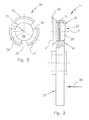
- FIG. 2 an enlarged lateral view of a cutter holder with cutter of the set of cutters of FIG. 1 ;
- FIG. 3 a top view onto a cutter of the set of cutters of FIG. 1 .
- FIG. 1 shows a set of cutters 10 , which in the illustrated example has two perforated discs 12 , 14 with cutter holders 11 , 13 arranged respectively in front.
- the set of cutters 10 is placed onto a shaft 15 of a mincer worm 16 , wherein the cutter holders 11 , 13 are driven in a rotating manner jointly with the worm 16 .
- the perforated discs 12 , 14 have two radially spaced rows of holes 17 , 18 or respectively 19 , 20 .
- the cutter holders 11 , 13 have three wings, of which two wings 21 , 22 or respectively 23 , 24 are to be seen in the lateral view.
- Each wing 21 , 22 , 23 , 24 carries a cutter 25 , 26 , 27 , 28 , the shape and mounting of which are described in greater detail by means of the enlarged illustration of the cutter holder 11 in FIG. 1 and by means of FIG. 2 .
- the wings 21 , 22 , 23 , 24 are of equal length and are preferably spaced apart from one another respectively by 120°.
- the axes R ( FIG.
- FIG. 1 illustrates in addition that the cutters 25 , 26 , 27 , 28 in the unstressed state are arranged with a small axial distance a in front of the perforated discs 12 , 14 , when no material which is for cutting is to be processed.
- the mincer with the set of cutters 10 according to the invention can therefore also run in a wear-free manner without material.
- FIG. 2 illustrates the mounting of the cutters 25 to 28 in the cutter holders 11 , 13 using the example of the cutter 26 .
- the cutter 26 has a round foot 29 , which is inserted into a round through-bore 30 in the wing 21 and is mounted there by a sealing ring 31 so as to be axially movable and rotatable.
- the foot 29 can carry out, in addition, limited tilting movements in the through-bore 30 , which is somewhat larger in diameter, so that the cutter 26 is additionally mounted in a floating manner in the cutter holder 11 .
- the sealing ring 31 prevents the penetration of pieces of meat.
- the cutter 26 has in addition a relief area E, the size of which depends on the material which is for cutting.
- the axial mobility enables a pressing of the cutter 26 against the perforated disc 12 by the material for cutting, which is transported up thereto in arrow direction 32 .
- the cutter can then also lie here with the entire surface against the perforated disc 11 , if this is not aligned exactly parallel to the cutter holder 11 .
- the material which is for cutting can set the cutter 26 in rotation, whereby a very good cut quality is produced, as tests have shown.
- the material which is held secure by the openings 19 , 20 of the perforated disc 12 is in fact cut at a distinctly higher percentage and not ground by crushing, as is the case in conventional sets of cutters.
- the cutter 26 has three wings 33 , 34 , 35 , which carry blades 36 , 37 , 38 respectively on their outer periphery, which in the illustrated example are provided with a serrated edge.
- the blades 36 , 37 , 38 are configured in the form of a circular arc and all have the same radial distance to the rotation axis A of the cutter 26 .
- the illustrated cutter shape here is only by way of example.
- the cutter 26 could also be round, i.e. could have no wings 33 , 34 , 35 and could carry a circular or polygonal blade.
- the shape of the cutter 26 can be selected according to the material for cutting which is to be processed and the end product which is to be produced. Through the simple plug-in connection between cutter 26 and cutter holder 11 , the cutters can be quickly exchanged for cutters of a different shape.
Landscapes
- Engineering & Computer Science (AREA)
- Food Science & Technology (AREA)
- Crushing And Pulverization Processes (AREA)
Applications Claiming Priority (4)
| Application Number | Priority Date | Filing Date | Title |
|---|---|---|---|
| DE102012108245 | 2012-09-05 | ||
| DE102012108245.6A DE102012108245A1 (de) | 2012-09-05 | 2012-09-05 | Messersatz für einen Fleischwolf |
| DE102012108245.6 | 2012-09-05 | ||
| PCT/EP2013/067398 WO2014037223A1 (de) | 2012-09-05 | 2013-08-21 | Messersatz für einen fleischwolf |
Publications (2)
| Publication Number | Publication Date |
|---|---|
| US20150251189A1 US20150251189A1 (en) | 2015-09-10 |
| US9643189B2 true US9643189B2 (en) | 2017-05-09 |
Family
ID=49035585
Family Applications (1)
| Application Number | Title | Priority Date | Filing Date |
|---|---|---|---|
| US14/425,413 Active 2034-01-07 US9643189B2 (en) | 2012-09-05 | 2013-08-21 | Blade set for a meat grinder |
Country Status (6)
| Country | Link |
|---|---|
| US (1) | US9643189B2 (es) |
| EP (1) | EP2892650B1 (es) |
| CN (1) | CN104768650B (es) |
| DE (1) | DE102012108245A1 (es) |
| ES (1) | ES2637246T3 (es) |
| WO (1) | WO2014037223A1 (es) |
Families Citing this family (2)
| Publication number | Priority date | Publication date | Assignee | Title |
|---|---|---|---|---|
| CN108405148B (zh) * | 2018-02-27 | 2020-06-09 | 瀚蓝驼王生物科技(广东)有限公司 | 一种病死动物肉骨粉加工装置 |
| DE102020108424A1 (de) | 2020-03-26 | 2021-09-30 | Greiner Maschinenbau Gmbh | Messer, Messersatz und Fleischwolf |
Citations (6)
| Publication number | Priority date | Publication date | Assignee | Title |
|---|---|---|---|---|
| GB363229A (en) | 1931-02-24 | 1931-12-17 | Adrianus Wilhelmus Van Berkel | Improvements relating to mincing machines |
| US1889381A (en) | 1930-10-21 | 1932-11-29 | William R Rush | Food chopper |
| DE577208C (de) | 1931-11-22 | 1933-05-26 | August Storck | Messerkopf fuer Fleischwoelfe |
| DE679144C (de) | 1937-12-14 | 1939-07-29 | Turner Akt Ges Maschf | Messerscheibe fuer Abhaeutevorrichtungen |
| DE4437144A1 (de) | 1994-10-18 | 1996-04-25 | Wolfgang Greiner | Messersatz für einen Fleischwolf und Klingeneinsatz für einen solchen |
| DE29905706U1 (de) | 1999-03-27 | 1999-07-08 | Tiromat Krämer + Grebe GmbH & Co. KG, 35216 Biedenkopf | Vorrichtung zum Zerkleinern und Sortieren von Lebensmitteln |
-
2012
- 2012-09-05 DE DE102012108245.6A patent/DE102012108245A1/de not_active Ceased
-
2013
- 2013-08-21 EP EP13753171.1A patent/EP2892650B1/de active Active
- 2013-08-21 US US14/425,413 patent/US9643189B2/en active Active
- 2013-08-21 CN CN201380046281.8A patent/CN104768650B/zh active Active
- 2013-08-21 WO PCT/EP2013/067398 patent/WO2014037223A1/de not_active Ceased
- 2013-08-21 ES ES13753171.1T patent/ES2637246T3/es active Active
Patent Citations (6)
| Publication number | Priority date | Publication date | Assignee | Title |
|---|---|---|---|---|
| US1889381A (en) | 1930-10-21 | 1932-11-29 | William R Rush | Food chopper |
| GB363229A (en) | 1931-02-24 | 1931-12-17 | Adrianus Wilhelmus Van Berkel | Improvements relating to mincing machines |
| DE577208C (de) | 1931-11-22 | 1933-05-26 | August Storck | Messerkopf fuer Fleischwoelfe |
| DE679144C (de) | 1937-12-14 | 1939-07-29 | Turner Akt Ges Maschf | Messerscheibe fuer Abhaeutevorrichtungen |
| DE4437144A1 (de) | 1994-10-18 | 1996-04-25 | Wolfgang Greiner | Messersatz für einen Fleischwolf und Klingeneinsatz für einen solchen |
| DE29905706U1 (de) | 1999-03-27 | 1999-07-08 | Tiromat Krämer + Grebe GmbH & Co. KG, 35216 Biedenkopf | Vorrichtung zum Zerkleinern und Sortieren von Lebensmitteln |
Also Published As
| Publication number | Publication date |
|---|---|
| ES2637246T3 (es) | 2017-10-11 |
| WO2014037223A1 (de) | 2014-03-13 |
| US20150251189A1 (en) | 2015-09-10 |
| EP2892650B1 (de) | 2017-05-17 |
| CN104768650A (zh) | 2015-07-08 |
| CN104768650B (zh) | 2017-11-07 |
| EP2892650A1 (de) | 2015-07-15 |
| DE102012108245A1 (de) | 2014-03-06 |
Similar Documents
| Publication | Publication Date | Title |
|---|---|---|
| EP3307499B1 (en) | Machines and methods for cutting products | |
| AU2007240821B8 (en) | Apparatus for cutting potatoes or similar vegetables | |
| AU2017356940B2 (en) | Knife assembly for slicing machines and machines equipped therewith | |
| EP3227067B1 (en) | Impeller and method of using it | |
| JP2016059916A (ja) | チョッパーとチョッパーの運転方法 | |
| US9643189B2 (en) | Blade set for a meat grinder | |
| US10549285B2 (en) | Grinder auger removal tool | |
| AU2014363915B2 (en) | Double-edged knife for food cutting apparatus | |
| JP2017080863A (ja) | 食材乾燥装置システム用の食材細断装置 | |
| EP2812143B1 (en) | Blade for cutting and/or grinding | |
| CN109259301B (zh) | 用于切割棒形制品的设备以及具有这种设备的机器 | |
| CN105010494A (zh) | 用于将冷冻的、束带状的食物切割为切片的装置和方法 | |
| CN104414509B (zh) | 一种粉碎刀组件 | |
| KR101289276B1 (ko) | 마늘 세절기 | |
| US3646979A (en) | Rotary blade for meat grinder | |
| JP4161214B2 (ja) | 鶏肉のほぐし装置 | |
| CN204339857U (zh) | 一种蒜姜切片机 | |
| US3563291A (en) | Rotary blade for meat grinder | |
| WO2007054981A1 (en) | Apparatus for cutting into pieces | |
| US20160214267A1 (en) | Rotating cutting blade assembly | |
| PL219145B1 (pl) | Urządzenie do poprzecznego przecinania tuszek ryb karpiowatych | |
| RU120337U1 (ru) | Устройство изготовления сырых, бланшированных мясных структур для вареных, ливерных колбас, паштетов и мясных начинок | |
| KR20140126997A (ko) | 막대형상의 식재료 절단장치 | |
| PL66769Y1 (pl) | Zestaw tnacy wilka do miesa |
Legal Events
| Date | Code | Title | Description |
|---|---|---|---|
| AS | Assignment |
Owner name: HEINRICH GMBH, GERMANY Free format text: ASSIGNMENT OF ASSIGNORS INTEREST;ASSIGNOR:GREINER, WOLFGANG;REEL/FRAME:035146/0370 Effective date: 20150226 |
|
| STCF | Information on status: patent grant |
Free format text: PATENTED CASE |
|
| MAFP | Maintenance fee payment |
Free format text: PAYMENT OF MAINTENANCE FEE, 4TH YR, SMALL ENTITY (ORIGINAL EVENT CODE: M2551); ENTITY STATUS OF PATENT OWNER: SMALL ENTITY Year of fee payment: 4 |
|
| MAFP | Maintenance fee payment |
Free format text: PAYMENT OF MAINTENANCE FEE, 8TH YR, SMALL ENTITY (ORIGINAL EVENT CODE: M2552); ENTITY STATUS OF PATENT OWNER: SMALL ENTITY Year of fee payment: 8 |