US9610120B2 - High-frequency treatment tool for endoscope - Google Patents
High-frequency treatment tool for endoscope Download PDFInfo
- Publication number
- US9610120B2 US9610120B2 US14/858,764 US201514858764A US9610120B2 US 9610120 B2 US9610120 B2 US 9610120B2 US 201514858764 A US201514858764 A US 201514858764A US 9610120 B2 US9610120 B2 US 9610120B2
- Authority
- US
- United States
- Prior art keywords
- circumferential surface
- distal end
- electrode
- conduit line
- outer circumferential
- Prior art date
- Legal status (The legal status is an assumption and is not a legal conclusion. Google has not performed a legal analysis and makes no representation as to the accuracy of the status listed.)
- Active
Links
Images


Classifications
-
- A—HUMAN NECESSITIES
- A61—MEDICAL OR VETERINARY SCIENCE; HYGIENE
- A61B—DIAGNOSIS; SURGERY; IDENTIFICATION
- A61B18/00—Surgical instruments, devices or methods for transferring non-mechanical forms of energy to or from the body
- A61B18/04—Surgical instruments, devices or methods for transferring non-mechanical forms of energy to or from the body by heating
- A61B18/12—Surgical instruments, devices or methods for transferring non-mechanical forms of energy to or from the body by heating by passing a current through the tissue to be heated, e.g. high-frequency current
- A61B18/14—Probes or electrodes therefor
- A61B18/1492—Probes or electrodes therefor having a flexible, catheter-like structure, e.g. for heart ablation
-
- A—HUMAN NECESSITIES
- A61—MEDICAL OR VETERINARY SCIENCE; HYGIENE
- A61B—DIAGNOSIS; SURGERY; IDENTIFICATION
- A61B17/00—Surgical instruments, devices or methods, e.g. tourniquets
- A61B17/32—Surgical cutting instruments
- A61B17/3203—Fluid jet cutting instruments
-
- A—HUMAN NECESSITIES
- A61—MEDICAL OR VETERINARY SCIENCE; HYGIENE
- A61B—DIAGNOSIS; SURGERY; IDENTIFICATION
- A61B18/00—Surgical instruments, devices or methods for transferring non-mechanical forms of energy to or from the body
- A61B2018/00053—Mechanical features of the instrument of device
- A61B2018/00059—Material properties
- A61B2018/00071—Electrical conductivity
- A61B2018/00077—Electrical conductivity high, i.e. electrically conducting
-
- A—HUMAN NECESSITIES
- A61—MEDICAL OR VETERINARY SCIENCE; HYGIENE
- A61B—DIAGNOSIS; SURGERY; IDENTIFICATION
- A61B18/00—Surgical instruments, devices or methods for transferring non-mechanical forms of energy to or from the body
- A61B2018/00053—Mechanical features of the instrument of device
- A61B2018/00059—Material properties
- A61B2018/00071—Electrical conductivity
- A61B2018/00083—Electrical conductivity low, i.e. electrically insulating
-
- A—HUMAN NECESSITIES
- A61—MEDICAL OR VETERINARY SCIENCE; HYGIENE
- A61B—DIAGNOSIS; SURGERY; IDENTIFICATION
- A61B18/00—Surgical instruments, devices or methods for transferring non-mechanical forms of energy to or from the body
- A61B2018/00053—Mechanical features of the instrument of device
- A61B2018/00107—Coatings on the energy applicator
- A61B2018/0013—Coatings on the energy applicator non-sticking
-
- A—HUMAN NECESSITIES
- A61—MEDICAL OR VETERINARY SCIENCE; HYGIENE
- A61B—DIAGNOSIS; SURGERY; IDENTIFICATION
- A61B18/00—Surgical instruments, devices or methods for transferring non-mechanical forms of energy to or from the body
- A61B2018/00053—Mechanical features of the instrument of device
- A61B2018/00184—Moving parts
- A61B2018/00196—Moving parts reciprocating lengthwise
-
- A—HUMAN NECESSITIES
- A61—MEDICAL OR VETERINARY SCIENCE; HYGIENE
- A61B—DIAGNOSIS; SURGERY; IDENTIFICATION
- A61B18/00—Surgical instruments, devices or methods for transferring non-mechanical forms of energy to or from the body
- A61B2018/00315—Surgical instruments, devices or methods for transferring non-mechanical forms of energy to or from the body for treatment of particular body parts
- A61B2018/00482—Digestive system
- A61B2018/00494—Stomach, intestines or bowel
-
- A—HUMAN NECESSITIES
- A61—MEDICAL OR VETERINARY SCIENCE; HYGIENE
- A61B—DIAGNOSIS; SURGERY; IDENTIFICATION
- A61B18/00—Surgical instruments, devices or methods for transferring non-mechanical forms of energy to or from the body
- A61B2018/00571—Surgical instruments, devices or methods for transferring non-mechanical forms of energy to or from the body for achieving a particular surgical effect
- A61B2018/00589—Coagulation
-
- A—HUMAN NECESSITIES
- A61—MEDICAL OR VETERINARY SCIENCE; HYGIENE
- A61B—DIAGNOSIS; SURGERY; IDENTIFICATION
- A61B18/00—Surgical instruments, devices or methods for transferring non-mechanical forms of energy to or from the body
- A61B2018/00571—Surgical instruments, devices or methods for transferring non-mechanical forms of energy to or from the body for achieving a particular surgical effect
- A61B2018/00601—Cutting
-
- A—HUMAN NECESSITIES
- A61—MEDICAL OR VETERINARY SCIENCE; HYGIENE
- A61B—DIAGNOSIS; SURGERY; IDENTIFICATION
- A61B18/00—Surgical instruments, devices or methods for transferring non-mechanical forms of energy to or from the body
- A61B2018/00982—Surgical instruments, devices or methods for transferring non-mechanical forms of energy to or from the body combined with or comprising means for visual or photographic inspections inside the body, e.g. endoscopes
-
- A—HUMAN NECESSITIES
- A61—MEDICAL OR VETERINARY SCIENCE; HYGIENE
- A61B—DIAGNOSIS; SURGERY; IDENTIFICATION
- A61B18/00—Surgical instruments, devices or methods for transferring non-mechanical forms of energy to or from the body
- A61B18/04—Surgical instruments, devices or methods for transferring non-mechanical forms of energy to or from the body by heating
- A61B18/12—Surgical instruments, devices or methods for transferring non-mechanical forms of energy to or from the body by heating by passing a current through the tissue to be heated, e.g. high-frequency current
- A61B18/14—Probes or electrodes therefor
- A61B2018/1405—Electrodes having a specific shape
-
- A—HUMAN NECESSITIES
- A61—MEDICAL OR VETERINARY SCIENCE; HYGIENE
- A61B—DIAGNOSIS; SURGERY; IDENTIFICATION
- A61B18/00—Surgical instruments, devices or methods for transferring non-mechanical forms of energy to or from the body
- A61B18/04—Surgical instruments, devices or methods for transferring non-mechanical forms of energy to or from the body by heating
- A61B18/12—Surgical instruments, devices or methods for transferring non-mechanical forms of energy to or from the body by heating by passing a current through the tissue to be heated, e.g. high-frequency current
- A61B18/14—Probes or electrodes therefor
- A61B2018/1472—Probes or electrodes therefor for use with liquid electrolyte, e.g. virtual electrodes
-
- A—HUMAN NECESSITIES
- A61—MEDICAL OR VETERINARY SCIENCE; HYGIENE
- A61B—DIAGNOSIS; SURGERY; IDENTIFICATION
- A61B18/00—Surgical instruments, devices or methods for transferring non-mechanical forms of energy to or from the body
- A61B18/04—Surgical instruments, devices or methods for transferring non-mechanical forms of energy to or from the body by heating
- A61B18/12—Surgical instruments, devices or methods for transferring non-mechanical forms of energy to or from the body by heating by passing a current through the tissue to be heated, e.g. high-frequency current
- A61B18/14—Probes or electrodes therefor
- A61B2018/1475—Electrodes retractable in or deployable from a housing
-
- A—HUMAN NECESSITIES
- A61—MEDICAL OR VETERINARY SCIENCE; HYGIENE
- A61B—DIAGNOSIS; SURGERY; IDENTIFICATION
- A61B2218/00—Details of surgical instruments, devices or methods for transferring non-mechanical forms of energy to or from the body
- A61B2218/001—Details of surgical instruments, devices or methods for transferring non-mechanical forms of energy to or from the body having means for irrigation and/or aspiration of substances to and/or from the surgical site
- A61B2218/002—Irrigation
Definitions
- the present invention relates to a high-frequency treatment tool for an endoscope capable of jetting a fluid forward while incising a biological tissue or the like.
- Patent Literature 1 Japanese Unexamined Patent Application, First Publication No. H11-114060
- Patent Literature 2 Japanese Unexamined Patent Application, First Publication No. 2001-178740
- a hollow electrode is connected and fixed to a distal end of an inner tube inserted to advance and retract in a mantle tube in an axial direction. Accordingly, as the inner tube advances and retracts in the mantle tube in the axial direction, the hollow electrode protrudes from the distal end of the mantle tube.
- a stopper formed of a metal ring configured to restrict excessive protrusion of the hollow electrode is disposed at an inner surface near the distal end of the mantle tube.
- a flange section protruding from an outer circumferential surface is formed at a rear half section of the hollow electrode.
- the liquid medicine (a fluid) can be sent from an injector to the hollow electrode via the inner tube.
- a high frequency voltage can be applied to the hollow electrode via the conductive wire by a high frequency power supply.
- the high-frequency treatment tool for an endoscope when the high-frequency treatment tool for an endoscope is used, before the treatment such as injection of a liquid medicine or the like is terminated and the hollow electrode is extracted from the mucosa, the high frequency voltage is applied to the hollow electrode to cauterize and solidify the mucosa around the hollow electrode. As a result, even when the hollow electrode is stuck into a large blood vessel, bleeding from a pinhole after the hollow electrode is extracted can be prevented.
- a high-frequency treatment tool for an endoscope includes: a sheath formed of a material having an insulation property; a shaft-shaped member formed of a material having conductivity and inserted to advance and retract in the sheath; and an electrode having a conduit line formed to jet forward a fluid supplied into the sheath, and connected to a distal end section of the shaft-shaped member, wherein the electrode has an outer circumferential surface electrically connected to a contacted tissue to perform treatment, an inner circumferential surface of the conduit line that faces the fluid when the fluid is supplied, and an arithmetic average roughness of the outer circumferential surface is larger than an arithmetic average roughness of the inner circumferential surface, and the arithmetic average roughness of the inner circumferential surface is 0.1 ⁇ m or less, the electrode is a tubular electrode having the conduit line formed along a longitudinal axis of the sheath, and an arithmetic average roughness of a distal end surface
- the outer circumferential surface of the electrode, a distal end surface of the electrode, and the inner circumferential surface of the conduit line may be composed of a surface of the material having conductivity that constitutes the electrode, and the arithmetic average roughness of the inner circumferential surface of the conduit line, which is a polished surface of the material having conductivity, may be 1 ⁇ 6 or less of the arithmetic average roughness of the outer circumferential surface.
- the electrode in the high-frequency treatment tool for the endoscope of the first aspect, may have: an electrode main body that is hollow; and an enveloping layer provided on an inner circumferential surface of the electrode main body.
- the electrode in the high-frequency treatment tool for the endoscope of the second aspect, may have a large diameter section disposed at a distal end side and a small diameter section disposed at a proximal end side, the conduit line may be opened at a distal end surface of the large diameter section through the small diameter section, the outer circumferential surface may be formed on an outer circumference of the small diameter section, and an outer circumferential edge section of the distal end surface, which is disposed at a distal end of the large diameter section, may be formed in a curved shape.
- the coefficient of friction in the outer circumferential surface may be larger than the coefficient of friction in the inner circumferential surface and equal to or more than the coefficient of friction in the distal end surface
- the outer circumferential surface may be configured to incise the tissue in contact with the outer circumferential surface
- the coefficient of friction in the distal end surface may be equal to or less than the coefficient of friction in the outer circumferential surface and larger than the coefficient of friction in the inner circumferential surface
- the distal end surface may be configured so that the electrode is moved while the distal end surface comes in contact with the tissue and prevent coagulated object discharged from the conduit line from remaining at the distal end surface
- the coefficient of friction in the inner circumferential surface may be smaller than the coefficient of friction in the
- a length of the electrode may be 1 mm or more and 5 mm or less, and an outer diameter of the small diameter section may be 0.3 mm or more and 0.5 mm or less, and an inner diameter of the conduit line may be 0.2 mm or more and 0.4 mm or less, and a supply pressure of the fluid in a supply port of the fluid in communication with the conduit line may be 100 kPa or more and 3000 kPa or less.
- FIG. 1 is a general view of a high-frequency treatment tool for an endoscope according to an embodiment of the present invention.
- FIG. 2 is a cross-sectional view in an axial direction of a distal end side in a pushed state of the high-frequency treatment tool for an endoscope according to the embodiment of the present invention.
- FIG. 3 is an enlarged view of a major part of the electrode member of FIG. 2 .
- FIG. 4 is a cross-sectional view taken along line A-A of FIG. 3 .
- FIG. 5 is a cross-sectional view in the axial direction of the distal end side in a returned state of the high-frequency treatment tool for an endoscope according to the embodiment of the present invention.
- FIG. 6 is a view showing a procedure using the high-frequency treatment tool for an endoscope according to the embodiment of the present invention, showing a state in which a lesion mucosa portion is raised.
- FIG. 7 is a view showing a procedure using the high-frequency treatment tool for an endoscope according to the embodiment of the present invention, showing a state in which the lesion mucosa portion is incised.
- FIG. 8 is a view showing a procedure using the high-frequency treatment tool for an endoscope according to the embodiment of the present invention, showing a state in which a body fluid enters a conduit line of the electrode member.
- FIG. 9 is a view showing a procedure using the high-frequency treatment tool for an endoscope according to the embodiment of the present invention, showing a state in which saline is jetted from the inside of the conduit line of the electrode member.
- FIG. 10 is a view showing a procedure using the high-frequency treatment tool for an endoscope according to the embodiment of the present invention, showing a state in which the lesion mucosa portion is exfoliated.
- FIG. 11 is a cross-sectional view in an axial direction of a distal end side of a high-frequency treatment tool for an endoscope according to a first variant of the embodiment of the present invention.
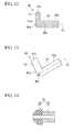
- FIG. 12 is a cross-sectional view in an axial direction of an electrode member of a high-frequency treatment tool for an endoscope according to a second variant of the embodiment of the present invention.
- FIG. 13 is a perspective view of the electrode member of the second variant of the embodiment of the present invention.
- FIG. 14 is a cross-sectional view in an axial direction of an electrode member of a high-frequency treatment tool for an endoscope according to a third variant of the embodiment of the present invention.
- FIG. 15 is a cross-sectional view in an axial direction of an electrode member of a high-frequency treatment tool for an endoscope according to a fourth variant of the embodiment of the present invention.
- FIG. 16 is a perspective view of the electrode member of the fourth variant of the embodiment of the present invention.
- FIGS. 1 to 16 an embodiment of a high-frequency treatment tool for an endoscope according to the present invention will be described with reference to FIGS. 1 to 16 . Further, in all of the following drawings, for the purpose of easy understanding of the drawings, thicknesses of components or the ratio of dimensions may be appropriately varied.
- FIG. 1 is a general view of a high-frequency treatment tool for an endoscope according to the embodiment.
- a high-frequency treatment tool 1 for an endoscope of the embodiment is used in a state in which a flexible insertion section 10 having a treatment section 20 installed at a distal end section thereof is inserted into a channel of an endoscope (not shown).
- FIG. 2 is a cross-sectional view in an axial direction of a distal end side in a pushed state of the high-frequency treatment tool for an endoscope according to the embodiment.
- the high-frequency treatment tool 1 for the endoscope according to the embodiment includes a flexible sheath 11 , a manipulation wire (a shaft-shaped member) 12 and an electrode member 21 .
- the sheath 11 is formed of a material having an electrical insulation property, for example, tetrafluoroethylene or the like.
- An outer diameter of the sheath 11 is set to a size that can be inserted in a channel of an endoscope (not shown).
- the manipulation wire 12 is inserted to advance and retract in the sheath 11 in a direction along a longitudinal axis C 1 of the sheath 11 .
- the manipulation wire 12 is formed of a material having conductivity such as a metal or the like.
- the sheath 11 and the manipulation wire 12 constitute the insertion section 10 (see FIG. 2 ) inserted in the channel of the endoscope.
- An insulation tip 13 is fixed to a distal end section of the sheath 11 by an adhesive or the like (not shown).
- the insulation tip 13 is formed of a material having heat resistance and an insulation property such as zirconia, ceramics, or the like, in a cylindrical shape.
- a cylinder hole 13 a in communication with an internal space of the sheath 11 and opened at a distal end is formed in the insulation tip 13 .
- a stepped portion 13 b is formed at the cylinder hole 13 a of the insulation tip 13 by increasing the diameter of the proximal end side.
- An outer circumferential stepped portion 13 c is formed at the outer circumferential surface of the insulation tip 13 by reducing the diameter of the proximal end side.
- the outer diameter of a portion closer to the distal end than the outer circumferential stepped portion 13 c of the insulation tip 13 is substantially equal to the outer diameter of the sheath 11 .
- the distal end section of the sheath 11 and the outer circumferential stepped portion 13 c of the insulation tip 13 are fixed.
- a liquid sending mouth piece 14 is attached to the proximal end section of the sheath 11 via a cylindrical connecting member 15 .
- An injection port (a supply port) 14 a in communication with an internal space 11 a of the sheath 11 is formed at the liquid sending mouth piece 14 .
- An anti-buckling tube 16 is attached to an outer circumferential surface of a connecting section between the sheath 11 and the liquid sending mouth piece 14 . The anti-buckling tube 16 is formed to prevent the proximal end section of the sheath 11 from being broken when the proximal end section of the sheath 11 is curved.
- An opening 14 b through which the proximal end section of the manipulation wire 12 is inserted is formed at the liquid sending mouth piece 14 .
- a seal material (not shown) is formed in the opening 14 b of the liquid sending mouth piece 14 .
- the liquid sending mouth piece 14 and the manipulation wire 12 are water-tightly sealed by the seal material such as an O-ring or the like, and the manipulation wire 12 is supported to advance and retract the manipulation wire 12 with respect to the liquid sending mouth piece 14 in a direction along the longitudinal axis C 1 .
- a water feed means such as a water feed tube or the like extending from a syringe or a water feed pump (not shown) is detachably attached to the injection port 14 a.
- the treatment section 20 has the electrode member (an electrode) 21 that is hollow.
- FIG. 3 is an enlarged view of a major part of the electrode member of FIG. 2 .
- the electrode member 21 is formed in a tubular shape, and the conduit line 21 a is formed therein.
- the electrode member 21 is connected to the distal end section of the manipulation wire 12 .
- a maximum protrusion length of the electrode member 21 from the sheath 11 in the direction along the longitudinal axis C 1 is preferably, for example, about 1 mm or more and 5 mm or less because the mucosa tissue is incised and the muscle layer portion is not excised.
- the electrode member 21 is formed of a material having conductivity such as stainless steel or the like.
- FIG. 4 is a cross-sectional view taken along line A-A shown in FIG. 3 .
- the electrode member 21 has a large diameter section 22 and a small diameter section 23 .
- the large diameter section 22 is disposed at the distal end side of the electrode member 21 .
- the small diameter section 23 is disposed closer to the proximal end than the large diameter section 22 , and has a smaller outer diameter than the large diameter section 22 .
- an outer circumferential edge section of a distal end surface 22 a of the large diameter section 22 is provided to form a circle when seen in a side view.
- the outer diameter of the small diameter section 23 is preferably, for example, about 0.3 mm or more and 0.5 mm or less in order to appropriately increase a density of a high-frequency current.
- the outer diameter of the small diameter section 23 is slightly smaller than the inner diameter of a portion closer to the distal end than the stepped portion 13 b in the cylinder hole 13 a of the insulation tip 13 .
- the small diameter section 23 of the electrode member 21 is inserted in the cylinder hole 13 a of the insulation tip 13 .
- a conduit line 21 a of the electrode member 21 is opened at the distal end surface of the large diameter section 22 through the small diameter section 23 . That is, the conduit line 21 a of the electrode member 21 passes through the electrode member 21 in the direction along the longitudinal axis C 1 , and the electrode member 21 is a tubular electrode at which the conduit line 21 a is formed along the longitudinal axis C 1 .
- the inner diameter of the conduit line 21 a is constant regardless of a position in the direction along the longitudinal axis C 1 .
- the inner diameter of the conduit line 21 a is preferably, for example, about 0.2 mm or more and 0.4 mm or less to achieve a jet pressure and a jet flow diameter for appropriately injecting saline or a liquid medicine under the mucosa.
- a communication hole 23 b passing from an outer circumferential surface 23 a of the small diameter section 23 to an inner circumferential surface is formed at an intermediate section of the small diameter section 23 in the direction along the longitudinal axis C 1 .
- An arithmetic average roughness (Ra) of an outer circumferential surface 22 b of the large diameter section 22 and the outer circumferential surface 23 a of the small diameter section 23 defined by JIS B0601-1994 is larger (rougher) than an arithmetic average roughness of an inner circumferential surface 21 b of the conduit line 21 a .
- the arithmetic average roughness of the inner circumferential surface 21 b of the conduit line 21 a is 0.1 ⁇ m (micrometer) or less, in this example, 0.02 ⁇ m. Further, the arithmetic average roughness of the inner circumferential surface 21 b is preferably 0.05 ⁇ m or less.
- the arithmetic average roughness of the outer circumferential surface 22 b of the large diameter section 22 and the arithmetic average roughness of the outer circumferential surface 23 a of the small diameter section 23 shown in FIGS. 3 and 4 are, for example, 6.3 ⁇ m.
- the arithmetic average roughness of the inner circumferential surface 21 b of the conduit line 21 a is 1 ⁇ 6 or less of the arithmetic average roughness of the outer circumferential surface 22 b of the large diameter section 22 , and 1 ⁇ 6 or less of the arithmetic average roughness of the outer circumferential surface 23 a of the small diameter section 23 .
- the arithmetic average roughness of the distal end surface 22 a of the large diameter section 22 is larger than the arithmetic average roughness of the inner circumferential surface 21 b of the conduit line 21 a , equal to or less than the arithmetic average roughness of the outer circumferential surface 22 b of the large diameter section 22 , and equal to or less than the arithmetic average roughness of the outer circumferential surface 23 a of the small diameter section 23 .
- the arithmetic average roughness of the distal end surface 22 a of the large diameter section 22 is, for example, 2.5 ⁇ m.
- coefficients of friction when the outer circumferential surface 23 a of the small diameter section 23 , the inner circumferential surface 21 b of the conduit line 21 a and the distal end surface 22 a of the electrode member 21 come in contact with tissues such as the mucosa to be described below or the like are set as follows.
- the coefficient of friction in the outer circumferential surface 23 a is larger than the coefficient of friction in the inner circumferential surface 21 b , and equal to or larger than the coefficient of friction in the distal end surface 22 a .
- the coefficient of friction in the distal end surface 22 a is equal to or smaller than the coefficient of friction in the outer circumferential surface 23 a , and larger than the coefficient of friction in the inner circumferential surface 21 b .
- the coefficient of friction in the inner circumferential surface 21 b is smaller than the coefficient of friction in the outer circumferential surface 23 a and the coefficient of friction in the distal end surface 22 a.
- the electrode member 21 can be formed by, for example, cutting an outer circumferential surface of a proximal end side of a pipe having an outer diameter larger than the large diameter section 22 of the electrode member 21 .
- a known polishing method such as electrolytic polishing using fine abrasive grain, chemical mechanical polishing (CMP), or the like can be appropriately selected and used.
- a cylindrical stopper member 25 is attached to an outer circumferential surface of the connecting section between the small diameter section 23 and the manipulation wire 12 , and the stopper member 25 connects the electrode member 21 and the manipulation wire 12 .
- a through-hole 25 a passing through the stopper member 25 from the outer circumferential surface to the inner circumferential surface is formed in the stopper member 25 .
- the through-hole 25 a of the stopper member 25 comes in communication with the communication hole 23 b of the electrode member 21 .
- the conduit line 21 a of the electrode member 21 comes in communication with the internal space 11 a of the sheath 11 via the communication hole 23 b of the electrode member 21 and the through-hole 25 a of the stopper member 25 .
- the outer diameter of the stopper member 25 is slightly smaller than an inner diameter of a portion closer to the proximal end than the stepped portion 13 b in the cylinder hole 13 a of the insulation tip 13 .
- the small diameter section 23 and the stopper member 25 inserted in the cylinder hole 13 a are configured to advance and retract a range closer to the proximal end than the stepped portion 13 b in the cylinder hole 13 a as the manipulation wire 12 is advanced and retracted.
- the high-frequency treatment tool 1 for the endoscope further includes a manipulation unit 30 .
- the manipulation unit 30 is installed at the proximal end section of the insertion section 10 .
- the manipulation unit 30 includes a manipulation unit main body 31 and a manipulation slider 32 .
- the manipulation unit main body 31 is fixed to the proximal end section of the liquid sending mouth piece 14 .
- the manipulation slider 32 is slidably installed with respect to the manipulation unit main body 31 .
- a slit 31 a is formed in the manipulation unit main body 31 along the longitudinal axis C 1 .
- the manipulation slider 32 is slidable with respect to the manipulation unit main body 31 along the slit 31 a .
- the manipulation unit main body 31 includes a finger hooking ring 31 b formed at the proximal end section.
- the manipulation slider 32 includes finger hooking rings 32 a and 32 b arranged in a direction perpendicular to the longitudinal axis C 1 .
- the manipulation slider 32 includes a connecting connector section 33 .
- a cord that leads to a high-frequency generator (not shown) is electrically connected to the connecting connector section 33 .
- the proximal end section of the manipulation wire 12 is electrically connected to the connecting connector section 33 while fixed to the manipulation slider 32 .
- the high-frequency treatment tool 1 for the endoscope is manipulated, for example, as a user serving as an operator inserts his/her thumb into the ring 31 b of the manipulation unit main body 31 and inserts his/her index finger and middle finger into the rings 32 a and 32 b of the manipulation slider 32 .
- the manipulation slider 32 can be slid with respect to the manipulation unit main body 31 in the direction along the longitudinal axis C 1 with one hand.
- the small diameter section 23 of the electrode member 21 can protrude toward the distal end further than the sheath 11 through the cylinder hole 13 a of the insulation tip 13 .
- Saline (a fluid) L 1 is supplied into the internal space 11 a of the sheath 11 from the injection port 14 a of the liquid sending mouth piece 14 .
- the physiological saline solution L 1 is supplied into the conduit line 21 a of the electrode member 21 through the through-hole 25 a of the stopper member 25 and the communication hole 23 b of the electrode member 21 to pass through the inner circumferential surface 21 b of the conduit line 21 a to be jetted in front of the electrode member 21 .
- FIG. 5 is a cross-sectional view in an axial direction of a distal end side in a returned state of the high-frequency treatment tool 1 for the endoscope according to the embodiment.
- the manipulation wire 12 is moved (returned) with respect to the sheath 11 toward the proximal end as the manipulation slider 32 is moved with respect to the manipulation unit main body 31 toward the proximal end.
- the small diameter section 23 of the electrode member 21 is accommodated in the internal space 11 a of the sheath 11 and the large diameter section 22 abuts the distal end surface of the insulation tip 13 . Accordingly, the returned state in which the manipulation wire 12 is returned to the proximal end side is positioned.
- a counter electrode plate (not shown) is mounted on a patient.
- the high-frequency treatment tool 1 for the endoscope in the returned state is endoscopically guided into the body cavity through the channel of the endoscope (not shown).
- the high-frequency treatment tool 1 for the endoscope is guided while the image acquired by the observation unit of the endoscope is observed using the display unit such as a monitor or the like.
- the distal end section of the insertion section 10 of the high-frequency treatment tool 1 for the endoscope protrudes from the channel of the endoscope, and the treatment section 20 is opposite to the lesion mucosa portion serving as the target area to be excised in the body cavity.
- FIG. 6 is a view showing a state in which the lesion mucosa portion is raised. As shown in FIG.
- the electrode member 21 pierces into the vicinity of a lesion mucosa portion P 1 , and the physiological saline solution L 1 accommodated in the syringe or the water feed pump is supplied into the internal space 11 a of the sheath 11 to be jetted to the front side from the electrode member 21 .
- the jetted physiological saline solution L 1 is injected into the submucosal layer of the lesion mucosa portion P 1 , and the lesion mucosa portion P 1 is raised.
- a high-frequency generator (not shown) is connected to the connecting connector section 33 of the manipulation unit 30 .
- a high frequency voltage is applied to the electrode member 21 via the connecting connector section 33 and the manipulation wire 12 by the high-frequency generator.
- the electrode member 21 reaches a high temperature of about 100° C.
- FIG. 7 is a view showing a state when the lesion mucosa portion is incised.
- a mucosa (a tissue) P 2 in contact with the electrode member 21 is incised.
- the arithmetic average roughness of the outer circumferential surface 23 a of the small diameter section 23 is larger than the arithmetic average roughness of the inner circumferential surface 21 b of the conduit line 21 a , specifically, for example, 6.3 ⁇ m.
- the coefficient of friction between the outer circumferential surface 23 a and the mucosa P 2 is set as described above. For this reason, the mucosa P 2 is securely caught on the outer circumferential surface 23 a of the small diameter section 23 , and the mucosa P 2 in contact with the outer circumferential surface 23 a is incised. In this way, the outer circumferential surface 23 a of the small diameter section 23 is configured to be electrically connected to the mucosa P 2 in contact with the outer circumferential surface 23 a to perform the treatment.
- the arithmetic average roughness of the distal end surface 22 a of the large diameter section 22 is larger than the arithmetic average roughness of the inner circumferential surface 21 b of the conduit line 21 a , and equal to or smaller than the arithmetic average roughness of the outer circumferential surface 23 a of the small diameter section 23 .
- the coefficient of friction between the distal end surface 22 a and the mucosa P 2 is set as described above. For this reason, even when the electrode member 21 is moved in a state in which the distal end surface 22 a of the large diameter section 22 comes in contact with the peripheral tissue, the distal end surface 22 a applies little load to the tissue.
- FIG. 8 is a view showing a state in which the body fluid enters a conduit line of the electrode member.
- a body fluid L 2 such as blood or the like enters the conduit line 21 a of the electrode member 21 from the distal end side through a capillary phenomenon or the like.
- the body fluid L 2 solidifies at the inner circumferential surface 21 b of the conduit line 21 a as heat from the electrode member 21 of a high temperature is transferred.
- Whether the body fluid L 2 solidifies in the conduit line 21 a can be identified by a force required when the physiological saline solution L 1 is supplied by the syringe or electric power required to drive the water feed pump. This is because a flow path area of the conduit line 21 a is reduced as the body fluid L 2 solidifies at the inner circumferential surface 21 b of the conduit line 21 a.
- FIG. 9 is a schematic view showing a state in which the physiological saline solution L 1 is jetted from the inside of the conduit line 21 a of the electrode member 21 .
- the physiological saline solution L 1 is jetted forward at a large pressure through the conduit line 21 a of the electrode member 21 .
- the arithmetic average roughness of the inner circumferential surface 21 b of the conduit line 21 a is 0.1 ⁇ m or less, and the coefficient of friction between the inner circumferential surface 21 b and the mucosa P 2 is set as described above.
- coagulated object L 3 of the body fluid L 2 coagulated at the inner circumferential surface 21 b of the conduit line 21 a are peeled off from the inner circumferential surface 21 b with the pressure of the physiological saline solution L 1 to be discharged. Since the coefficient of friction between the arithmetic average roughness of the distal end surface 22 a of the large diameter section 22 and the mucosa P 2 is set as described above, the coagulated object L 3 discharged from the conduit line 21 a can be prevented from remaining on the distal end surface 22 a.
- the physiological saline solution L 1 fed from the syringe or the water feed pump may be supplied at a pressure of about 100 kPa (kilopascals) or more and 3000 kPa or less in the injection port 14 a of the liquid sending mouth piece 14 .
- the supply pressure is less than 100 kPa, exfoliation of the coagulated object L 3 may be insufficient.
- the supply pressure exceeds 3000 kPa, the sheath 11 may be damaged due to an inflow pressure of the physiological saline solution L 1 .
- FIG. 10 is a view showing a state in which the lesion mucosa portion is exfoliated.
- the electrode member 21 abuts a cut edge P 3 obtained by incising a periphery of the lesion mucosa portion P 1 , and the lesion mucosa portion P 1 is sequentially incised to entirely excise and exfoliate the lesion mucosa portion P 1 .
- the high-frequency treatment tool 1 for the endoscope enters the returned state to be extracted from the inside of the channel of the endoscope to the hand side.
- Grasping forceps (not shown) are inserted in the empty channel of the endoscope.
- the grasping forceps are manipulated to endoscopically extract the lesion mucosa portion P 1 to terminate a series of treatments.
- the arithmetic average roughness of the inner circumferential surface 21 b of the electrode member 21 is 0.1 ⁇ m or less.
- the coagulated object L 3 stuck to the inner circumferential surface 21 b can be easily exfoliated from the inner circumferential surface 21 b at the pressure of the physiological saline solution L 1 , and can be easily washed away to the outside of the electrode member 21 . Accordingly, clogging of the conduit line 21 a of the electrode member 21 with the coagulated object L 3 can be limited.
- the mucosa P 2 is securely caught by the outer circumferential surface 23 a of the small diameter section 23 , and heat is securely transferred from the electrode member 21 having the high temperature to the mucosa P 2 . Accordingly, the mucosa P 2 can be securely incised using the electrode member 21 .
- the arithmetic average roughness of the distal end surface 22 a of the large diameter section 22 is larger than the arithmetic average roughness of the inner circumferential surface 21 b of the conduit line 21 a , machining of the distal end surface 22 a of the large diameter section 22 can be relatively easily performed by known polishing or the like. Since the arithmetic average roughness of the distal end surface 22 a of the large diameter section 22 is equal to or smaller than the arithmetic average roughness of the outer circumferential surface 23 a of the small diameter section 23 , the load applied to a peripheral tissue by the distal end surface 22 a of the large diameter section 22 can be limited.
- the surface of the large diameter section 22 has an appropriate roughness, slippage of the large diameter section 22 with respect to the tissue or catching of the large diameter section 22 to the tissue cannot easily occur, and control precision of the high-frequency treatment tool 1 for the endoscope becomes better.
- the coagulated object L 3 can be securely discharged from the conduit line 21 a in a state in which the coagulated object L 3 exfoliated from the inner circumferential surface 21 b of the electrode member 21 do not remain on the surface of the large diameter section 22 .
- the electrode member 21 of the high-frequency treatment tool 1 for the endoscope according to the embodiment can be variously deformed.
- FIG. 11 is a cross-sectional view showing a distal end portion of an electrode member 41 of a first variant of the embodiment.
- the electrode member 41 may be provided instead of the electrode member 21 according to the embodiment.
- the electrode member 41 of the variant is different from the embodiment in that an enveloping layer 43 is formed at an inner circumferential surface 42 a of an electrode main body 42 .
- the enveloping layer 43 may be formed of a material having a heat resistance and a smooth surface, for example, tetrafluoroethylene or the like.
- An arithmetic average roughness of an inner circumferential surface 43 a of the enveloping layer 43 is 0.1 ⁇ m or less.
- the arithmetic average roughness of the distal end surface 22 a of the large diameter section 22 is larger than the arithmetic average roughness of the inner circumferential surface 43 a of the enveloping layer 43 .
- FIGS. 12 and 13 are cross-sectional views showing a distal end portion of an electrode member 46 of a second variant of the embodiment.
- a large diameter section 47 may be formed to extend in only one direction crossing the longitudinal axis C 1 .
- the electrode member 46 is formed in an L shape as a whole.
- the arithmetic average roughness of each of the distal end surface 47 a and the surface 47 b of the large diameter section 47 is larger than the arithmetic average roughness of an inner circumferential surface 46 b of a conduit line 46 a of the electrode member 46 , and equal to or less than the arithmetic average roughness of the outer circumferential surface 23 a of the small diameter section 23 .
- FIG. 14 is a cross-sectional view showing a distal end portion of an electrode member 51 of a third variant of the embodiment.
- a large diameter section 52 may be formed in a hemispherical shape having a curved surface protruding toward the distal end side.
- the large diameter section 52 is formed of a material having an insulation property such as a ceramic, the tissue in contact with the distal end surface of the electrode member 51 can be prevented from being incised.
- FIG. 15 is a cross-sectional view showing a distal end portion of an electrode member 56 of a fourth variant of the embodiment.
- FIG. 16 is a perspective view showing the distal end portion of the electrode member 56 of the fourth variant of the embodiment.
- a large diameter section 57 is also formed in a triangular plate shape when seen in a direction along the longitudinal axis C 1 .
- the shape of the large diameter section when seen in the direction along the longitudinal axis C 1 and a direction perpendicular to the longitudinal axis C 1 is not limited to the triangular shape but may be a polygonal shape such as a rectangular shape or the like or may be an oval shape.
- the arithmetic average roughness of the distal end surface 22 a of the large diameter section 22 is larger than the arithmetic average roughness of the inner circumferential surface 21 b of the conduit line 21 a , and equal to or smaller than the arithmetic average roughness of the outer circumferential surface 23 a of the small diameter section 23 .
- the arithmetic average roughness of the distal end surface 22 a of the large diameter section 22 may be equal to or smaller than the arithmetic average roughness of the inner circumferential surface 21 b of the conduit line 21 a , and may be larger than the arithmetic average roughness of the outer circumferential surface 23 a of the small diameter section 23 .
- the fluid is the physiological saline solution L 1
- the fluid is not limited thereto but may be sterilized water, liquid medicine, or the like.
Landscapes
- Health & Medical Sciences (AREA)
- Surgery (AREA)
- Life Sciences & Earth Sciences (AREA)
- Engineering & Computer Science (AREA)
- Molecular Biology (AREA)
- General Health & Medical Sciences (AREA)
- Veterinary Medicine (AREA)
- Public Health (AREA)
- Nuclear Medicine, Radiotherapy & Molecular Imaging (AREA)
- Biomedical Technology (AREA)
- Heart & Thoracic Surgery (AREA)
- Medical Informatics (AREA)
- Animal Behavior & Ethology (AREA)
- Cardiology (AREA)
- Physics & Mathematics (AREA)
- Plasma & Fusion (AREA)
- Otolaryngology (AREA)
- Surgical Instruments (AREA)
Applications Claiming Priority (3)
| Application Number | Priority Date | Filing Date | Title |
|---|---|---|---|
| JP2013-212061 | 2013-10-09 | ||
| JP2013212061 | 2013-10-09 | ||
| PCT/JP2014/077070 WO2015053365A1 (fr) | 2013-10-09 | 2014-10-09 | Instrument de traitement haute-fréquence pour endoscope |
Related Parent Applications (1)
| Application Number | Title | Priority Date | Filing Date |
|---|---|---|---|
| PCT/JP2014/077070 Continuation WO2015053365A1 (fr) | 2013-10-09 | 2014-10-09 | Instrument de traitement haute-fréquence pour endoscope |
Publications (2)
| Publication Number | Publication Date |
|---|---|
| US20160008063A1 US20160008063A1 (en) | 2016-01-14 |
| US9610120B2 true US9610120B2 (en) | 2017-04-04 |
Family
ID=52813180
Family Applications (1)
| Application Number | Title | Priority Date | Filing Date |
|---|---|---|---|
| US14/858,764 Active US9610120B2 (en) | 2013-10-09 | 2015-09-18 | High-frequency treatment tool for endoscope |
Country Status (5)
| Country | Link |
|---|---|
| US (1) | US9610120B2 (fr) |
| EP (1) | EP3056158B1 (fr) |
| JP (1) | JP5775989B1 (fr) |
| CN (1) | CN105073049B (fr) |
| WO (1) | WO2015053365A1 (fr) |
Families Citing this family (13)
| Publication number | Priority date | Publication date | Assignee | Title |
|---|---|---|---|---|
| CN107683119B (zh) * | 2015-06-18 | 2021-07-27 | 奥林巴斯株式会社 | 高频处置器具 |
| CN105832411B (zh) * | 2016-01-25 | 2020-10-27 | 安进医疗科技(北京)有限公司 | 用于电磁刀手术的内镜电极系统 |
| CN106214247B (zh) * | 2016-07-04 | 2018-08-14 | 南京微创医学科技股份有限公司 | 一种双极高频电刀 |
| JP1576779S (fr) * | 2016-10-05 | 2017-05-22 | ||
| JP1576777S (fr) * | 2016-10-05 | 2017-05-22 | ||
| US20200188011A1 (en) * | 2017-03-29 | 2020-06-18 | Kyocera Corporation | Flow channel member and electrosurgical knife head using the same |
| GB2579493B (en) * | 2017-07-14 | 2022-10-26 | Actuated Medical Inc | Device for aiding in the positioning and anchoring of an endoscope during gastronintestinal procedures |
| US10864006B2 (en) * | 2017-08-31 | 2020-12-15 | Carefusion 2200, Inc. | Adjustable length laparoscopic instrument |
| CN108272503B (zh) * | 2018-03-07 | 2024-04-19 | 南微医学科技股份有限公司 | 一种可双通道注液的双极高频电刀 |
| CN108523985B (zh) * | 2018-04-23 | 2024-05-07 | 南微医学科技股份有限公司 | 一种多功能高频电切开刀 |
| US20190328451A1 (en) * | 2018-04-25 | 2019-10-31 | Boston Scientific Scimed, Inc. | Multifunctional electrosurgical instruments with dynamic electrode assemblies |
| EP3845176A4 (fr) * | 2018-08-30 | 2022-05-18 | Kyocera Corporation | Tête de scalpel électrique |
| CN111544110B (zh) * | 2020-05-06 | 2021-07-20 | 安进医疗科技(北京)有限公司 | 内镜手术电极组件 |
Citations (12)
| Publication number | Priority date | Publication date | Assignee | Title |
|---|---|---|---|---|
| JPH11114060A (ja) | 1997-10-16 | 1999-04-27 | Asahi Optical Co Ltd | 内視鏡用注射具 |
| JP2001178740A (ja) | 1999-12-24 | 2001-07-03 | Olympus Optical Co Ltd | 内視鏡治療装置 |
| JP2004167081A (ja) | 2002-11-21 | 2004-06-17 | Olympus Corp | 高周波ナイフ |
| JP2006115966A (ja) | 2004-10-20 | 2006-05-11 | Pentax Corp | 内視鏡用高周波処置具 |
| JP2009240380A (ja) | 2008-03-28 | 2009-10-22 | Fujifilm Corp | 高周波ナイフおよび高周波ナイフシステム |
| JP2010042155A (ja) | 2008-08-13 | 2010-02-25 | Olympus Medical Systems Corp | 内視鏡用処置具 |
| US20100111708A1 (en) | 2008-10-30 | 2010-05-06 | Seiko Epson Corporation | Fluid ejection system, fluid ejection system drive method, and surgical apparatus |
| US20120035607A1 (en) | 2009-04-16 | 2012-02-09 | Dietmar Karwei | Endoscopic surgical instrument |
| JP2012075618A (ja) | 2010-09-30 | 2012-04-19 | Kaneka Corp | 医療用カテーテル |
| US20140207134A1 (en) * | 2012-09-12 | 2014-07-24 | Olympus Medical Systems Corp. | High-frequency knife |
| US9237918B2 (en) * | 2012-09-10 | 2016-01-19 | Olympus Corporation | Endoscope treatment tool |
| US9387034B2 (en) * | 2012-10-17 | 2016-07-12 | Olympus Corporation | High-frequency knife |
Family Cites Families (2)
| Publication number | Priority date | Publication date | Assignee | Title |
|---|---|---|---|---|
| JPH01114060A (ja) | 1987-10-28 | 1989-05-02 | Hitachi Ltd | 集積回路装置 |
| JP2010046200A (ja) * | 2008-08-20 | 2010-03-04 | Fujinon Corp | 高周波処置具 |
-
2014
- 2014-10-09 JP JP2015516355A patent/JP5775989B1/ja active Active
- 2014-10-09 WO PCT/JP2014/077070 patent/WO2015053365A1/fr active Application Filing
- 2014-10-09 CN CN201480019282.8A patent/CN105073049B/zh active Active
- 2014-10-09 EP EP14851723.8A patent/EP3056158B1/fr active Active
-
2015
- 2015-09-18 US US14/858,764 patent/US9610120B2/en active Active
Patent Citations (16)
| Publication number | Priority date | Publication date | Assignee | Title |
|---|---|---|---|---|
| JPH11114060A (ja) | 1997-10-16 | 1999-04-27 | Asahi Optical Co Ltd | 内視鏡用注射具 |
| JP2001178740A (ja) | 1999-12-24 | 2001-07-03 | Olympus Optical Co Ltd | 内視鏡治療装置 |
| JP2004167081A (ja) | 2002-11-21 | 2004-06-17 | Olympus Corp | 高周波ナイフ |
| US20040210215A1 (en) | 2002-11-21 | 2004-10-21 | Olympus Corporation | Diathermic cutter |
| JP2006115966A (ja) | 2004-10-20 | 2006-05-11 | Pentax Corp | 内視鏡用高周波処置具 |
| JP2009240380A (ja) | 2008-03-28 | 2009-10-22 | Fujifilm Corp | 高周波ナイフおよび高周波ナイフシステム |
| JP2010042155A (ja) | 2008-08-13 | 2010-02-25 | Olympus Medical Systems Corp | 内視鏡用処置具 |
| EP2322109A1 (fr) | 2008-08-13 | 2011-05-18 | Olympus Medical Systems Corp. | Instrument de traitement pour endoscope |
| JP2010106748A (ja) | 2008-10-30 | 2010-05-13 | Seiko Epson Corp | 流体噴射システム、流体噴射システムの駆動方法、手術装置 |
| US20100111708A1 (en) | 2008-10-30 | 2010-05-06 | Seiko Epson Corporation | Fluid ejection system, fluid ejection system drive method, and surgical apparatus |
| US20120035607A1 (en) | 2009-04-16 | 2012-02-09 | Dietmar Karwei | Endoscopic surgical instrument |
| JP2012523863A (ja) | 2009-04-16 | 2012-10-11 | エルベ エレクトロメディジン ゲーエムベーハー | 内視鏡外科器具 |
| JP2012075618A (ja) | 2010-09-30 | 2012-04-19 | Kaneka Corp | 医療用カテーテル |
| US9237918B2 (en) * | 2012-09-10 | 2016-01-19 | Olympus Corporation | Endoscope treatment tool |
| US20140207134A1 (en) * | 2012-09-12 | 2014-07-24 | Olympus Medical Systems Corp. | High-frequency knife |
| US9387034B2 (en) * | 2012-10-17 | 2016-07-12 | Olympus Corporation | High-frequency knife |
Non-Patent Citations (1)
| Title |
|---|
| Dec. 16, 2014 International Search Report issued in International Patent Application No. PCT/JP2014/077070. |
Also Published As
| Publication number | Publication date |
|---|---|
| EP3056158B1 (fr) | 2019-04-24 |
| WO2015053365A1 (fr) | 2015-04-16 |
| EP3056158A4 (fr) | 2017-06-07 |
| US20160008063A1 (en) | 2016-01-14 |
| JP5775989B1 (ja) | 2015-09-09 |
| EP3056158A1 (fr) | 2016-08-17 |
| JPWO2015053365A1 (ja) | 2017-03-09 |
| CN105073049B (zh) | 2017-10-10 |
| CN105073049A (zh) | 2015-11-18 |
Similar Documents
| Publication | Publication Date | Title |
|---|---|---|
| US9610120B2 (en) | High-frequency treatment tool for endoscope | |
| CA3090198C (fr) | Couteau electrochirurgical a haute frequence bipolaire a injection en double canal | |
| US9138283B2 (en) | High-frequency knife | |
| US9387034B2 (en) | High-frequency knife | |
| KR100595803B1 (ko) | 고주파 나이프 및 내시경 장치 | |
| JP5755121B2 (ja) | 内視鏡用高周波処置具 | |
| JP2009112788A (ja) | 高周波処置具 | |
| JP3235996U (ja) | 医療用接続装置 | |
| KR101830085B1 (ko) | 복수개의 처치구 병용이 가능한 내시경 점막하 절개박리를 위한 고주파 나이프 | |
| CN105395251B (zh) | 一种内镜用高频电刀 | |
| JP2010042155A (ja) | 内視鏡用処置具 | |
| WO2022007732A1 (fr) | Outil haute fréquence ayant de multiples fonctions | |
| WO2022007733A1 (fr) | Dispositif de coupe haute fréquence multifonctionnel pour endoscope | |
| JP2010213946A (ja) | 高周波処置具 | |
| US20110245829A1 (en) | Endoscopic high-frequency treatment instrument | |
| JP4965416B2 (ja) | 高周波処置具 | |
| CN213406254U (zh) | 一种内窥镜用多功能高频刀具 | |
| US20230248424A1 (en) | Endoscopic treatment device | |
| WO2017122608A1 (fr) | Instrument de traitement haute fréquence pour endoscope | |
| WO2022007734A1 (fr) | Instrument électrique haute fréquence destiné à être utilisé avec un endoscope | |
| WO2017122607A1 (fr) | Instrument de traitement haute fréquence pour endoscope | |
| JP4373890B2 (ja) | 内視鏡用高周波処置具 | |
| US20220287766A1 (en) | Systems and methods for a dissection tool | |
| CN214318121U (zh) | 一种配合内窥镜使用的高频电器械 | |
| JP7473691B2 (ja) | 内視鏡用処置具 |
Legal Events
| Date | Code | Title | Description |
|---|---|---|---|
| AS | Assignment |
Owner name: OLYMPUS CORPORATION, JAPAN Free format text: ASSIGNMENT OF ASSIGNORS INTEREST;ASSIGNORS:WAKE, FUMINORI;SAKAMOTO, YUJI;SIGNING DATES FROM 20150907 TO 20150910;REEL/FRAME:036603/0790 |
|
| AS | Assignment |
Owner name: OLYMPUS CORPORATION, JAPAN Free format text: CORRECTIVE ASSIGNMENT TO CORRECT THE ASSIGNEE ADDRESS PREVIOUSLY RECORDED AT REEL: 036603 FRAME: 0790. ASSIGNOR(S) HEREBY CONFIRMS THE ASSIGNMENT;ASSIGNOR:OLYMPUS CORPORATION;REEL/FRAME:041809/0681 Effective date: 20160425 |
|
| STCF | Information on status: patent grant |
Free format text: PATENTED CASE |
|
| MAFP | Maintenance fee payment |
Free format text: PAYMENT OF MAINTENANCE FEE, 4TH YEAR, LARGE ENTITY (ORIGINAL EVENT CODE: M1551); ENTITY STATUS OF PATENT OWNER: LARGE ENTITY Year of fee payment: 4 |