US9599222B2 - Diaphragm pump - Google Patents
Diaphragm pump Download PDFInfo
- Publication number
- US9599222B2 US9599222B2 US14/355,016 US201214355016A US9599222B2 US 9599222 B2 US9599222 B2 US 9599222B2 US 201214355016 A US201214355016 A US 201214355016A US 9599222 B2 US9599222 B2 US 9599222B2
- Authority
- US
- United States
- Prior art keywords
- piston
- cylinder
- rolling diaphragm
- ejection
- suction
- Prior art date
- Legal status (The legal status is an assumption and is not a legal conclusion. Google has not performed a legal analysis and makes no representation as to the accuracy of the status listed.)
- Active, expires
Links
- 238000005096 rolling process Methods 0.000 claims abstract description 80
- 239000010409 thin film Substances 0.000 claims description 16
- 238000000605 extraction Methods 0.000 claims description 11
- 239000000463 material Substances 0.000 claims description 6
- YCKRFDGAMUMZLT-UHFFFAOYSA-N Fluorine atom Chemical compound [F] YCKRFDGAMUMZLT-UHFFFAOYSA-N 0.000 abstract description 7
- 229910052731 fluorine Inorganic materials 0.000 abstract description 7
- 239000011737 fluorine Substances 0.000 abstract description 7
- 239000007788 liquid Substances 0.000 description 122
- 239000000126 substance Substances 0.000 description 44
- 238000011010 flushing procedure Methods 0.000 description 28
- 238000004140 cleaning Methods 0.000 description 24
- 238000000034 method Methods 0.000 description 12
- 238000005086 pumping Methods 0.000 description 10
- 238000004519 manufacturing process Methods 0.000 description 8
- 230000008569 process Effects 0.000 description 6
- 230000004913 activation Effects 0.000 description 5
- 238000005452 bending Methods 0.000 description 4
- 229920001343 polytetrafluoroethylene Polymers 0.000 description 4
- 239000004810 polytetrafluoroethylene Substances 0.000 description 4
- 239000011347 resin Substances 0.000 description 4
- 229920005989 resin Polymers 0.000 description 4
- 230000008859 change Effects 0.000 description 3
- 230000006837 decompression Effects 0.000 description 2
- 238000007599 discharging Methods 0.000 description 2
- 238000005304 joining Methods 0.000 description 2
- 230000007246 mechanism Effects 0.000 description 2
- 238000000465 moulding Methods 0.000 description 2
- 238000012856 packing Methods 0.000 description 2
- -1 polytetrafluoroethylene Polymers 0.000 description 2
- 230000004044 response Effects 0.000 description 2
- 239000004065 semiconductor Substances 0.000 description 2
- 206010034719 Personality change Diseases 0.000 description 1
- 230000004931 aggregating effect Effects 0.000 description 1
- 238000013459 approach Methods 0.000 description 1
- 230000008901 benefit Effects 0.000 description 1
- 230000015572 biosynthetic process Effects 0.000 description 1
- 230000008878 coupling Effects 0.000 description 1
- 238000010168 coupling process Methods 0.000 description 1
- 238000005859 coupling reaction Methods 0.000 description 1
- 238000005520 cutting process Methods 0.000 description 1
- 230000007547 defect Effects 0.000 description 1
- 238000010586 diagram Methods 0.000 description 1
- 230000000694 effects Effects 0.000 description 1
- 239000012530 fluid Substances 0.000 description 1
- 239000004973 liquid crystal related substance Substances 0.000 description 1
- 238000002156 mixing Methods 0.000 description 1
- 230000002093 peripheral effect Effects 0.000 description 1
- 238000003825 pressing Methods 0.000 description 1
- 230000009467 reduction Effects 0.000 description 1
Images


Classifications
-
- F—MECHANICAL ENGINEERING; LIGHTING; HEATING; WEAPONS; BLASTING
- F16—ENGINEERING ELEMENTS AND UNITS; GENERAL MEASURES FOR PRODUCING AND MAINTAINING EFFECTIVE FUNCTIONING OF MACHINES OR INSTALLATIONS; THERMAL INSULATION IN GENERAL
- F16J—PISTONS; CYLINDERS; SEALINGS
- F16J3/00—Diaphragms; Bellows; Bellows pistons
- F16J3/02—Diaphragms
-
- F—MECHANICAL ENGINEERING; LIGHTING; HEATING; WEAPONS; BLASTING
- F04—POSITIVE - DISPLACEMENT MACHINES FOR LIQUIDS; PUMPS FOR LIQUIDS OR ELASTIC FLUIDS
- F04B—POSITIVE-DISPLACEMENT MACHINES FOR LIQUIDS; PUMPS
- F04B43/00—Machines, pumps, or pumping installations having flexible working members
- F04B43/0009—Special features
- F04B43/0054—Special features particularities of the flexible members
- F04B43/0063—Special features particularities of the flexible members bell-shaped flexible members
-
- F—MECHANICAL ENGINEERING; LIGHTING; HEATING; WEAPONS; BLASTING
- F04—POSITIVE - DISPLACEMENT MACHINES FOR LIQUIDS; PUMPS FOR LIQUIDS OR ELASTIC FLUIDS
- F04B—POSITIVE-DISPLACEMENT MACHINES FOR LIQUIDS; PUMPS
- F04B43/00—Machines, pumps, or pumping installations having flexible working members
- F04B43/02—Machines, pumps, or pumping installations having flexible working members having plate-like flexible members, e.g. diaphragms
- F04B43/04—Pumps having electric drive
-
- F—MECHANICAL ENGINEERING; LIGHTING; HEATING; WEAPONS; BLASTING
- F04—POSITIVE - DISPLACEMENT MACHINES FOR LIQUIDS; PUMPS FOR LIQUIDS OR ELASTIC FLUIDS
- F04B—POSITIVE-DISPLACEMENT MACHINES FOR LIQUIDS; PUMPS
- F04B53/00—Component parts, details or accessories not provided for in, or of interest apart from, groups F04B1/00 - F04B23/00 or F04B39/00 - F04B47/00
- F04B53/007—Cylinder heads
-
- F—MECHANICAL ENGINEERING; LIGHTING; HEATING; WEAPONS; BLASTING
- F04—POSITIVE - DISPLACEMENT MACHINES FOR LIQUIDS; PUMPS FOR LIQUIDS OR ELASTIC FLUIDS
- F04B—POSITIVE-DISPLACEMENT MACHINES FOR LIQUIDS; PUMPS
- F04B53/00—Component parts, details or accessories not provided for in, or of interest apart from, groups F04B1/00 - F04B23/00 or F04B39/00 - F04B47/00
- F04B53/14—Pistons, piston-rods or piston-rod connections
-
- F—MECHANICAL ENGINEERING; LIGHTING; HEATING; WEAPONS; BLASTING
- F04—POSITIVE - DISPLACEMENT MACHINES FOR LIQUIDS; PUMPS FOR LIQUIDS OR ELASTIC FLUIDS
- F04B—POSITIVE-DISPLACEMENT MACHINES FOR LIQUIDS; PUMPS
- F04B53/00—Component parts, details or accessories not provided for in, or of interest apart from, groups F04B1/00 - F04B23/00 or F04B39/00 - F04B47/00
- F04B53/16—Casings; Cylinders; Cylinder liners or heads; Fluid connections
-
- F—MECHANICAL ENGINEERING; LIGHTING; HEATING; WEAPONS; BLASTING
- F05—INDEXING SCHEMES RELATING TO ENGINES OR PUMPS IN VARIOUS SUBCLASSES OF CLASSES F01-F04
- F05B—INDEXING SCHEME RELATING TO WIND, SPRING, WEIGHT, INERTIA OR LIKE MOTORS, TO MACHINES OR ENGINES FOR LIQUIDS COVERED BY SUBCLASSES F03B, F03D AND F03G
- F05B2210/00—Working fluid
- F05B2210/10—Kind or type
- F05B2210/11—Kind or type liquid, i.e. incompressible
-
- F—MECHANICAL ENGINEERING; LIGHTING; HEATING; WEAPONS; BLASTING
- F05—INDEXING SCHEMES RELATING TO ENGINES OR PUMPS IN VARIOUS SUBCLASSES OF CLASSES F01-F04
- F05B—INDEXING SCHEME RELATING TO WIND, SPRING, WEIGHT, INERTIA OR LIKE MOTORS, TO MACHINES OR ENGINES FOR LIQUIDS COVERED BY SUBCLASSES F03B, F03D AND F03G
- F05B2280/00—Materials; Properties thereof
- F05B2280/40—Organic materials
- F05B2280/4003—Synthetic polymers, e.g. plastics
Definitions
- the present invention relates to a diaphragm pump including a rolling diaphragm, and more specifically to a diaphragm pump which is suitably used in application of a chemical liquid or blending of chemical liquids in a process of producing a semiconductor, a liquid crystal, an organic EL, a solar cell, an LED, or the like.
- a decompression chamber which, in the back side of the rolling diaphragm, is formed while being surrounded by the cylinder, the piston, and the rolling diaphragm.
- the rolling diaphragm has an inner circumferential portion which is supported by the piston, and an outer circumferential portion which is supported by the cylinder through a folded portion of the outer circumference of the piston.
- a pumping operation of sucking and ejecting a fluid is performed by a reciprocal movement between a suction position (see FIG. 3 of Patent Literature 1 above) where the piston is mostly retractively moved, and an ejection position (see FIG. 4 of Patent Literature 1 above) where the piston is projectively moved.
- the flushing mode In a diaphragm pump, in a liquid replacement in which liquids such as chemical liquids are replaced, an operation which is called the flushing mode is sometimes conducted.
- the flushing mode in order to completely discharge the liquid in the pump chamber, the piston is moved toward the projection side as far as possible, or projectively moved to the maximum projecting position.
- the piston In the flushing mode, the piston is maximally projectively moved to the maximum projecting position, and therefore the folded portion which is formed in the tip end side of the rolling diaphragm is changed from a folded attitude (bent attitude) having a U-like sectional shape to an extended attitude in which the portion is elongated and extended. Therefore, a liquid stagnating in the folded portion is moved toward the pump chamber to be easily discharged, and the liquid replacement can be smoothly performed.
- the curved portion 10 which should be smoothly arcuately deformed to be in an extended attitude by extending (opening) the folded portion 3 d and the like has a distorted shape.
- the curved portion 10 means a portion which, when the rolling diaphragm 3 is in an extended attitude as shown in FIG. 14 , connects the inner circumferential portion 3 c with an outer circumferential portion 3 g .
- the curved portion 10 is curved without distortion to form a portion smoothly connecting the inner circumferential portion 3 c with the outer circumferential portion 3 g as shown in FIG. 2 , the curved portion has the expected (normal) shape.
- the curved portion 10 When the piston is at the maximum projecting position, as described above, the curved portion 10 is not in an extended attitude having the expected smooth curved shape (see FIG. 2 ), and actually has a distorted shape as shown in FIGS. 14( a ), ( b ) , and therefore a situation where a liquid in the folded portion 3 d is hardly discharged from the pump chamber occurs.
- a large quantity of a cleaning liquid or a chemical liquid which is to be loaded for replacement, and a long time period are required.
- a case where the liquid in the folded portion is not sufficiently discharged and stagnates therein to aggregate may sometimes occur.
- there is a fear that a product failure or reduction of the product yield may be caused.
- An example of a product failure is a case where an aggregated liquid in a process of producing a semiconductor is formed as a stagnant foreign material, and there arises a possibility that a wafer defect may occur.
- Patent Literature 1 Japanese Patent Application Laid-Open No. 2010-019141
- the invention of claim 1 is a diaphragm pump having: a rolling diaphragm 3 including: an inner circumferential portion 3 c which is supported by a piston 2 that is reciprocally movable in a cylinder 1 , and which elongates along an outer circumferential surface 2 e of the piston 2 ; an outer circumferential portion 3 e which is supported by the cylinder 1 , and which elongates along an inner circumferential surface 1 r of the cylinder 1 ; and a folded portion 3 d which is formed by folding back in a tubular space 13 between the cylinder 1 and the piston 2 , to extend from the inner circumferential portion 3 c to the outer circumferential portion 3 e , the rolling diaphragm being made of a flexible material; and a pump chamber 4 which is separated by the rolling diaphragm 3 in the cylinder 1 , and a volume of which is changed in a manner that the volume is reduced by a projective movement of the piston 2 , and the volume is increased by
- the invention of claim 2 is characterized in that, in the diaphragm pump of claim 1 , the rolling diaphragm 3 is set to a state in which, when the piston 2 is at a maximum projecting position f where the piston is mostly projectively moved, the extended attitude is obtained, and the piston 2 is configured to be reciprocally movable between the maximum projecting position f and a suction position k where the retractive movement is performed from the maximum projecting position f.
- the invention of claim 3 is characterized in that, in the diaphragm pump of claim 2 , the piston 2 is configured to be reciprocally movable between an ejection position t where the retractive movement is performed from the maximum projecting position f, and where the projective movement is performed from the suction position k, and the suction position k, and, when the piston 2 is at the ejection position t and on a side of the suction position k with respect to the ejection position, the rolling diaphragm 3 is maintained in a folded attitude having the folded portion 3 d.
- the invention of claim 4 is characterized in that, in the diaphragm pump of claim 1 , the cylinder 1 has: a cylinder body 1 A in which the piston 2 is accommodated in a reciprocally movable manner; and a cylinder head 1 B including supply/ejection paths 6 a , 7 a for the pump chamber 4 , the rolling diaphragm 3 includes a thick outer circumference ring portion 3 g which is continuous with a tip end side of the outer circumferential portion 3 e , and
- the invention of claim 5 is characterized in that, in the diaphragm pump of claim 4 , the rolling diaphragm 3 has a configuration where a thin-film annular extraction portion 3 f which extends in an inner radial direction from an inner circumferential end of the outer circumference ring portion 3 g is connected to the outer circumferential portion 3 e.
- the rolling diaphragm 3 is produced in the extended attitude (see FIGS. 2 and 5 ). Even when the piston 2 is at any position within the reciprocal movement range, therefore, the folded portion 3 d is maintained in a state where an attitude change (shape change) between a folded attitude (bent attitude) and the extended attitude is smoothly performed.
- the curved portion 10 which is formed by the movement is not formed into a distorted shape such as shown in FIG. 14 , and the rolling diaphragm 3 having an expected extended attitude having the curved portion 10 which smoothly connects the inner circumferential portion 3 c with the outer circumference ring portion 3 g is obtained. Therefore, elements (the edge portion 41 , the reversely bent portion 42 , the undulated portion 43 , and the like) which block a liquid stagnating in the folded portion 3 d from flowing in the projective movement direction are not formed, and discharging can be smoothly conducted.
- a diaphragm pump P in which, when the rolling diaphragm 3 is caused to have the extended attitude by projectively moving the piston 2 as far as possible, the curved portion 10 which is formed by opening of the folded portion 3 d is not formed into a distorted shape, but has the expected shape that is smoothly curved, the liquid quantity and time period that are required for a liquid replacement in the flushing mode can be reduced, and the liquid replacement efficiency is improved.
- the piston 2 can be reciprocally moved between the maximum projecting position f where the rolling diaphragm 3 has the extended attitude, and the suction position k where the rolling diaphragm has the folded attitude.
- the piston 2 can be reciprocally moved also between the ejection position t and suction position k in both of which the rolling diaphragm 3 has the folded attitude, and, in a liquid replacement, the piston 2 can be reciprocally moved between the maximum projecting position f and the suction position k (operated in the flushing mode), and, in a liquid transfer, reciprocally moved between the ejection position t and the suction position k (operated in the normal mode).
- the outer circumference ring portion 3 g of the rolling diaphragm 3 can be supported by the structure of coupling the cylinder body 1 A and cylinder head 1 B which are components of the cylinder 1 . Therefore, it is possible to provide the diaphragm pump P having a more rational structure.
- FIG. 1 is a partially cutaway side view showing the structure of a diaphragm pump.
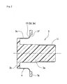
- FIG. 2 is a partially cutaway side view showing a rolling diaphragm in a free state.
- FIG. 3 is a sectional view of main portions of the pump in which a piston is at a suction position.
- FIG. 4 is a sectional view of main portions of the pump in which the piston is at an ejection position.
- FIG. 5 is a sectional view of main portions of the pump in which the piston is at a maximum projecting position.
- FIG. 6 shows main portions of the pump in a normal mode, (a) is a sectional view in the case where the piston is returned to the ejection position in accordance with activation, and (b) is a sectional view in the case where a suction step is ended and the piston is at the suction position.
- FIG. 7 shows main portions of the pump in the normal mode, (a) is a sectional view in the case where the suction step is ended and the piston is at the ejection position, and (b) is a sectional view in the case where a suck-back step is ended and the piston is at a suck-back position.
- FIG. 8 shows main portions of the pump in the normal mode, (a) is a sectional view in the case where the piston is returned from the suck-back position to the ejection position, and (b) is a sectional view in the case where the suction step is ended and the piston is at the suction position.
- FIG. 9 shows main portions of the pump in a flushing mode, (a) is a sectional view in the case where the piston is returned to the ejection position in accordance with activation, and (b) is a sectional view in the case where an excessive ejection step is ended and the piston is at the maximum projecting position.
- FIG. 10 shows main portions of the pump in the flushing mode, (a) is a sectional view in the case where a whole suction step is ended and the piston is at the suction position, and (b) is a sectional view in the case where a flushing step is ended and the piston is at the maximum projecting position.
- FIG. 11 is a flow chart showing the procedure of a liquid replacement in the diaphragm pump.
- FIG. 12 is a diagram showing a liquid pump system using the diaphragm pump.
- FIG. 13 is a partially cutaway side view showing a conventional rolling diaphragm in a free state.
- FIGS. 14( a ) and 14( b ) are views of main portions of pumps showing disadvantageous examples of the prior art, respectively.
- FIG. 1 shows a diaphragm pump P and a pump apparatus A having it
- FIG. 12 shows a liquid pump system B including the pump apparatus A.
- the pump apparatus A is configured by including the diaphragm pump (also called a rolling diaphragm pump) P, a linear actuator (motor) 8 which drives the diaphragm pump P, etc.
- the internal structure of the linear actuator 8 is known (Patent Literature 1 above and the like), and its detailed description and illustration are omitted.
- the reference numeral 20 denotes an engagement pin for detecting the piston position
- 25 denotes an aspiration port which is connected to an aspirator (pressure reducing unit) 14 (see FIG. 12 ).
- the piston 2 which can be reciprocally moved in the cylinder 1 is reciprocally driven in the direction of the axis C by the linear actuator 8 , whereby a liquid can be sucked through a suction port 6 and then ejected through an ejection port 7 .
- FIG. 1 shows a state where the piston 2 is located at the ejection position t.
- the liquid pump system B is configured by having a chemical liquid tank 15 , the pump apparatus A, a filter 16 , a nozzle 17 , an opening/closing valve 21 of the suction side, an opening/closing valve 22 of the ejection side, a suction side flow path 26 , an ejection side flow path 27 , etc.
- the opening/closing valve 21 of the suction side is placed in the middle of the suction side flow path 26 which elongates between the suction port 6 of the pump apparatus A and the chemical liquid tank 15
- the opening/closing valve 22 of the ejection side and the filter 16 are placed in the ejection side flow path 27 which elongates between the ejection port 7 of the pump apparatus A and the nozzle 17 .
- a control apparatus 30 is disposed which governs driving states of a suction side driving mechanism 28 that drives the opening/closing of the opening/closing valve 21 of the suction side, an ejection side driving mechanism 29 that drives the opening/closing of the opening/closing valve 22 of the ejection side, and the pump apparatus A.
- the reference numeral 31 denotes a wafer which is a target (target of liquid supply) of application of a liquid e such as a chemical liquid.
- the diaphragm pump P is configured by including: the cylinder 1 ; the piston 2 which is accommodated in the cylinder 1 in a reciprocally movable manner; a rolling diaphragm 3 which is equipped between the cylinder 1 and the piston 2 ; a pump chamber 4 which is separated by the rolling diaphragm 3 in the cylinder 1 ; the suction port 6 and ejection port 7 which are formed in the cylinder 1 ; etc.
- the piston 2 is accommodated in the cylinder 1 so as to be slidably movable in the direction of the axis C, and interlockingly coupled to the linear actuator 8 via an output screw shaft 18 .
- the volume of the pump chamber 4 is reduced by projectively moving the piston 2 in the direction of the arrow AA, and that of the pump chamber 4 is increased by retractively moving the piston 2 in the direction of the arrow BB.
- the cylinder 1 is configured by including a cylinder body 1 A which is bolted to the linear actuator 8 , and a cylinder head 1 B which is bolted to the cylinder body 1 A through an outer circumference ring portion 3 g of the rolling diaphragm 3 .
- the cylinder body 1 A has: a cylinder inner circumferential surface 1 a having a circular sectional shape; a rolling inner circumferential surface (an example of “inner circumferential surface of the cylinder”) 1 r having a circular sectional shape in which the diameter and the sectional area are larger than those of the cylinder inner circumferential surface 1 a , and formed on the projection side of the cylinder inner circumferential surface 1 a ; and an inclined inner circumferential surface 1 k which connects the cylinder inner circumferential surface 1 a with the rolling inner circumferential surface 1 r .
- the cylinder inner circumferential surface 1 a and the rolling inner circumferential surface 1 r have the common axis C.
- the cylinder head 1 B includes a suction path (an example of supply/ejection paths) 6 a which is opened in the pump chamber 4 , and which communicates with the suction port 6 , and an ejection path (an example of supply/ejection paths) 7 a which is opened in the pump chamber 4 , and which communicates with the ejection port 7 .
- the suction path 6 a and the ejection path 7 a are set as linear pipe conduits which are identical with each other in position in the direction of the axis C and diameter.
- the piston 2 is configured as a straight drum shape which has: an annular packing groove 2 d that is formed in a middle portion in the movement direction (direction of the axis C) of the piston; a tip end portion 2 b that is on the side of the cylinder head 1 B with respect to the groove; a basal end portion 2 a that is in the opposite side or on the piston root side; a screw hole 2 c that is formed in the tip end portion 2 b ; and the like, and which is fitted into the cylinder inner circumferential surface 1 a.
- the above-described engagement pin 20 stands from the basal end portion 2 a.
- the rolling diaphragm 3 is made of a fluorine resin such as PTFE (polytetrafluoroethylene), and is configured by having the screw shaft portion 3 a , the flange head portion 3 b , the thin inner circumferential portion 3 c , the folded portion 3 d , the thin outer circumferential portion 3 e , the thin-film annular extraction portion 3 f , and the outer circumference ring portion 3 g.
- PTFE polytetrafluoroethylene
- the screw shaft portion 3 a is a columnar portion which is to be inserted into the screw hole 2 c of the piston 2 , and the flange head portion 3 b is formed in the tip end of the screw shaft portion.
- the thin inner circumferential portion 3 c is a thin cylindrical portion which is extended toward the root side of the piston 2 in a state where it elongates from an outer end portion of the flange head portion 3 b along the outer circumferential surface 2 e of the piston 2 .
- the outer circumference ring portion 3 g which is thick in the direction of the axis C is formed in the outermost circumferential side of the rolling diaphragm 3 , and the thin-film annular extraction portion 3 f is extended in an inner radial direction from the inner circumferential end of the outer circumference ring portion 3 g .
- the thin outer circumferential portion 3 e which is formed in succession to the extraction portion 3 f is a thin cylindrical portion which is extended toward the root side of the piston 2 in a state where it elongates along the rolling inner circumferential surface 1 r.
- the end of the thin inner circumferential portion 3 c on the side of the root of the piston 2 , and that of thin outer circumferential portion 3 e on the side of the root of the piston 2 are integrated with each other through the thin folded portion 3 d which is folded back in a tubular space 13 between the cylinder 1 and the piston 2 .
- the sectional shape of the folded portion 3 d has a U-like shape which is convex toward the root side of the piston 2 .
- a known structure is employed in which, when the formation position of the folded portion 3 d is moved in the direction of the axis C in conjunction with the movement of the piston 2 , the rolling diaphragm 3 is smoothly deformed to maintain the air tightness (liquid tightness) of the pump chamber 4 that undergoes a volumetric change.
- the rolling diaphragm 3 can be attached to the piston 2 in a state where an outer circumferential portion of the flange head portion 3 b butts against an annular tip end surface 2 f of the piston 2 , and the thin inner circumferential portion 3 c is closely fitted onto the tip end portion 2 b .
- the outer circumference ring portion 3 g is integrally attached to the cylinder 1 in a state where it is pressingly held between the cylinder body 1 A and the cylinder head 1 B.
- the pump chamber 4 is a space portion surrounded by the cylinder head 1 B and the rolling diaphragm 3 , and a ring-like decompression chamber 5 which is surrounded by the rolling diaphragm 3 , the piston 2 , and the cylinder body 1 A, and which communicates with the aspiration port 25 is formed on the side of the back surface (the root side of the piston 2 ) of the rolling diaphragm 3 .
- An O-ring 9 made of fluorine rubber or the like is disposed between the joining surfaces of the cylinder body 1 A and the outer circumference ring portion 3 g .
- the gap between the joining surfaces of the cylinder head 1 B and the outer circumference ring portion 3 g is sealed by pressing a lip seal portion (not shown) formed in the cylinder head 1 B, against the surface of the outer circumference ring portion 3 g.
- FIGS. 3, 6 ( b ), 8 ( b ), and 10 ( a ) show main portions of the diaphragm pump P in the case where the piston 2 is at a position where it is moved at the maximum degree to the root side of the piston 2 (on the side of the linear actuator 8 ), i.e., a suction position k, and a state where the tip end of the flange head portion 3 b is substantially flush with that of the cylinder body 1 A in the direction of the axis C is set.
- the thin outer circumferential portion 3 e which elongates along the rolling inner circumferential surface 1 r has a relatively long length in the direction of the axis C
- the thin inner circumferential portion 3 c which elongates along the outer circumferential surface 2 e has a relatively short length in the direction of the axis C.
- the suction position k is not always necessary to be a position where the piston 2 is moved at the maximum degree to the root side of the piston 2 , and may be a position in front of it.
- FIGS. 1, 4, 6 ( a ), 7 ( a ), 8 ( a ), and 9 ( a ) show the piston 2 in the case where it is at an ejection position t which is separated to some extent from the suction position k in the direction of the arrow AA.
- the ejection position t is set to a position where the tip end of the flange head portion 3 b reaches the peripheral edges of the opening holes of the suction path 6 a and ejection path 7 a which are formed in the pump chamber 4 , on the side of the root of the piston 2 in the direction of the axis C.
- the thin outer circumferential portion 3 e which elongates along the rolling inner circumferential surface 1 r has a relatively short length in the direction of the axis C (shorter than that in the case of the suction position k), and the thin inner circumferential portion 3 c which elongates along the outer circumferential surface 2 e has a relatively long length in the direction of the axis C (longer than the in the case of the suction position k).
- FIGS. 5, 9 ( b ), and 10 ( b ) show the piston 2 in the case where it is at a maximum projecting position (flushing position) f where the piston is mostly projectively moved, and it is set that the tip end of the flange head portion 3 b approaches the inner surface 12 of the cylinder head 1 B in a manner where it almost butts thereagainst, and the volume of the pump chamber 4 is minimum.
- the curved portion 10 is formed when the extraction portion 3 f , the outer circumferential portion 3 e , and the folded portion 3 d [these three portions ( 3 f , 3 e , 3 d ) are formed when the piston 2 is at the suction position k, the ejection position t, or the like] are deformed so as to exhibit a single sectional shape by means of a curved surface which is smoothly continued from the outer circumference ring portion 3 g in the direction (direction of the arrow AA) of the pump chamber 4 .
- the rolling diaphragm 3 is deformed so that the inner circumferential portion 3 c is extended in accordance with the projective movement of the piston 2 , and also the position of the folded portion 3 d is moved toward the pump chamber 4 .
- the piston 2 is projectively moved beyond the ejection position t, therefore, a state is produced where the outer circumferential portion 3 e vanishes by a further movement of the folded portion 3 d toward the pump chamber 4 .
- the extraction portion 3 f which has been in an attitude where the direction is changed by 90 deg. toward the root of the piston 2 has an attitude where it is straightly directed to the radially inner side, and the attitude of the rolling diaphragm 3 is changed to one where the curved portion 10 appears in place of the outer circumferential portion 3 e and the folded portion 3 d .
- the rolling diaphragm 3 is changed from the folded attitude (see FIGS. 3 and 4 ) having the outer circumferential portion 3 e and the folded portion 3 d , to the extended attitude (see FIGS. 2 and 5 ) having the extraction portion 3 f and curved portion 10 which are straightly directed to the radially inner side.
- the extraction portion 3 f which is formed so as to be directed to the radially inner side from the inner circumferential end of the outer circumference ring portion 3 g has an attitude where the direction is changed by 90 deg., so that the inner circumferential end of the outer circumference ring portion 3 g is smoothly connected to the outer circumferential portion 3 e , no bent portion is formed in a thin film portion u, and the shape can be smoothly changed.
- the usual driving method in which a chemical liquid is sucked and ejected is referred to as the normal mode, and the driving method which is performed in replacement of liquids is referred to as the flushing mode.
- an origin return step of moving (or maintaining) the piston 2 to the ejection position t as shown in FIG. 6( a ) is performed in response to instructions for the normal mode (including activation of the pump apparatus A, and the like).
- FIG. 6( b ) shows a state where the piston 2 is retractively moved in the direction of the arrow BB to be located at the suction position k, i.e., the end state of the suction step.
- the opening/closing valve 21 on the suction side is in the opened state
- the opening/closing valve 22 on the ejection side is in the closed state.
- a chemical liquid is sucked into the pump chamber 4 through the suction port 6 as shown in the arrow CC.
- FIG. 7( a ) shows a state where the piston 2 is projectively moved in the direction of the arrow AA to be located at the ejection position t, i.e., the end state of the ejection step.
- the opening/closing valve 21 on the suction side is in the closed state
- the opening/closing valve 22 on the ejection side is in the opened state.
- the chemical liquid in the pump chamber 4 is ejected through the ejection port 7 as indicated by the arrow DD.
- FIG. 7( b ) shows a state where the piston 2 is retractively moved in the direction of the arrow BB to be located at a suck-back position s, i.e., the end state of the suck-back step.
- the suck-back step is a known step in which, in order to prevent the chemical liquid e from dripping from the nozzle 17 (see FIG. 12 ), the chemical liquid in the ejection side flow path 27 is sucked for a moment [see the arrow EE in FIG. 7( b ) ].
- FIG. 8( a ) shows the state where the piston 2 which is projectively moved from the suck-back position s is returned to the ejection position t, i.e., the end state of the second origin return step.
- FIG. 8( b ) shows the end state of the suction step in which the piston 2 is retractively moved in the direction of the arrow BB to be located at the suction position k.
- FIGS. 6( b ) and 7( a ) are separately drawn, but the figures are identical to each other.
- the pumping operation is performed in the state where the folded attitude in which the folded portion 3 d is formed in the rolling diaphragm 3 is maintained, and the sectional shape of the rolling diaphragm 3 (particularly, the film-like portion) is maintained constant. Therefore, the flow quantity of the liquid which is transferred in each of the pumping operations can be kept constant.
- the flushing mode is a driving method which is performed in replacement of the liquid that is the target of pumping.
- the liquid replacement is performed in the flowchart shown in FIG. 11 .
- the suction side flow path 26 is detached from the tank of the chemical liquid A. Then, “(1) Evacuation of chemical liquid A” is performed in which a pumping operation (so-called a pump idle operation) of sucking and ejecting the air is continuously executed until the chemical liquid A is almost ejected and vanishes.
- a pumping operation so-called a pump idle operation
- the chemical liquid A remaining in the pump chamber 4 is ejected in a spray-like form while being mixed with the air, and evacuated from the pump chamber 4 .
- the chemical liquid A that is the target of pumping is replaced with the chemical liquid B, and then the diaphragm pump P is driven in the above-described normal mode, whereby the chemical liquid B is supplied to the wafer or the like.
- a process of sucking and ejecting the cleaning liquid A may be performed several times between the steps of “(3) Standing after filling with cleaning liquid A” and “(4) Evacuation of cleaning liquid A” to wash away the chemical liquid A which may possibly still remain in the pump chamber 4 .
- a process in which the ejected chemical liquid B is not supplied to the wafer or the like, but is discarded may be performed so as to conduct a more complete liquid replacement.
- the piston 2 In the flushing mode, the piston 2 is operated in the following manner in the steps of “(1) Evacuation of chemical liquid A” and “(4) Evacuation of cleaning liquid A”.
- the origin return step of moving (or maintaining) the piston 2 to the ejection position t as shown in FIG. 9( a ) is performed in response to instructions for the flushing mode.
- FIG. 9( b ) shows a state where the piston 2 is mostly (as far as possibly) projectively moved in the direction of the arrow AA to be located at the maximum projecting position (flushing position) f, i.e., the end state of the excessive ejection step.
- the opening/closing valve 21 on the suction side is in the closed state
- the opening/closing valve 22 on the ejection side is in the opened state.
- most (almost all) of the chemical liquid (or the cleaning liquid) in the pump chamber 4 is ejected from the ejection port 7 as shown in the arrow GG.
- FIG. 10( a ) shows a state where the piston 2 is retractively moved in the direction of the arrow BB to be located at the suction position k, i.e., the end state of the whole suction step.
- the opening/closing valve 21 on the suction side is in the opened state
- the opening/closing valve 22 on the ejection side is in the closed state.
- the chemical liquid (or the cleaning liquid) is sucked from the suction port 6 into the pump chamber 4 [see the arrow HH in FIG. 10( a ) ].
- the quantity of suction in the whole suction step is definitely larger than that in the suction step in the above-described normal mode.
- FIG. 10( b ) shows a state where the piston 2 is mostly (as far as possibly) projectively moved in the direction of the arrow AA to be located at the maximum projecting position (flushing position) f, i.e., the end state of the flushing step.
- the opening/closing valve 21 on the suction side is in the closed state
- the opening/closing valve 22 on the ejection side is in the opened state.
- the pump chamber 4 in which the piston 2 is at the suction position k and the volume is maximum is reduced in one stroke in volume to have the minimum volume, by the projective movement of the piston 2 to the maximum projecting position f, and an almost all of the chemical liquid (or the cleaning liquid) with which the pump chamber 4 is filled can be discharged [see the arrow II in FIG. 10( b ) ].
- the conventional rolling diaphragm 3 was produced in the attitude corresponding to the case where the piston 2 is for example at the ejection position t, i.e., the folded attitude in which, as shown in FIG. 13 , the folded portion 3 d and the outer circumferential portion 3 e are formed in the thin film portion u that is a thin portion between the flange head portion 3 b and the outer circumference ring portion 3 g.
- the rolling diaphragm 3 made of a flexible material such as a fluorine resin
- the thin film portion u is smoothly deformed.
- the diaphragm pump P of the invention is characterized in that the rolling diaphragm 3 is produced in the extended attitude (see FIG.
- the rolling diaphragm 3 is set so that, when the piston 2 is in the state (state where the piston 2 at the maximum projecting position f) where it is mostly projectively moved, the extended attitude is obtained.
- the rolling diaphragm 3 which is in the extended attitude shown in FIG. 2 , the folded portion 3 d and the thin outer circumferential portion 3 e are not formed, and instead the curved portion 10 which exhibits a gentle and smooth curved sectional shape is formed. Therefore, the rolling diaphragm 3 is produced in the state where the portion between the thin inner circumferential portion 3 c and the outer circumference ring portion 3 g is formed into the curved portion 10 in which the shape is smoothly changed.
- the reference numeral 11 denotes an external thread which is to be screwed with the piston 2 .
- the rolling diaphragm 3 is made of a flexible material such as a fluorine resin, the thin film portion u can be easily deformed into a folded shape.
- the reason of this is as follows.
- the folded attitude (see FIGS. 3 and 4 ) of the thin film portion u in which the folded portion 3 d and the outer circumferential portion 3 e appear is formed by deformation which is directed in the direction of further increasing the bending of the curved portion 10 that appears during the production. When the portion is bent in the same direction, it can be smoothly deformed.
- the extended attitude shown in FIG. 2 is obtained at the one end (maximum projecting position f) of the whole moving region of the piston 2 .
- the curved portion 10 Even when the curved portion 10 has a small tendency due to production (bending tendency), the curved portion 10 cannot be bent or deformed in a direction opposite to its bending direction, and therefore there is no possibility that a distorted sectional shape is formed by the tendency due to production.
- the diaphragm pump P of the invention having the rolling diaphragm 3 which is produced in the extended attitude (see FIGS. 2 and 5 ), even when the piston 2 is at any position including the suction position k, the ejection position t, and the maximum projecting position f, therefore, the thin film portion u is maintained in a state where the sectional shapes of a folded attitude, an extended attitude, and the like are smoothly deformed (changed).
- the rolling diaphragm 3 is obtained that has the expected extended attitude in which the thin film portion u is not formed into a distorted shape such as shown in FIG. 14 , and has the curved portion 10 that is smoothly arcuately deformed. Therefore, elements (the edge portion 41 , the reversely bent portion 42 , the undulated portion 43 , and the like) which block a liquid stagnating in the folded portion 3 d from flowing in the projective movement direction are not formed, and discharging can be smoothly conducted.
- the shape of the curved portion 10 is a smooth shape, and therefore the chemical liquid A with which the pump chamber 4 is filled promptly fits to the curved portion 10 . Also in the step of “(6) Standing after filling with chemical liquid B”, similarly, the chemical liquid B with which the pump chamber 4 is filled promptly fits to the curved portion 10 . Therefore, the time period for the steps can be shortened.
- the ejection position t is set to the position which is moved toward the root side of the piston 2 with respect to the maximum projecting position (flushing position) f.
- the curved portion 10 which is formed by opening the folded portion 3 d does not have a distorted shape. Therefore, a liquid stagnation portion is hardly formed, and it is possible to prevent a chemical liquid from aggregating and solidifying. Consequently, a trouble due to a liquid stagnation phenomenon in a liquid transfer can be suppressed.
- production has a concept including production by cutting, and production by molding (die molding).
Landscapes
- Engineering & Computer Science (AREA)
- General Engineering & Computer Science (AREA)
- Mechanical Engineering (AREA)
- Reciprocating Pumps (AREA)
Applications Claiming Priority (3)
| Application Number | Priority Date | Filing Date | Title |
|---|---|---|---|
| JP2011-240280 | 2011-11-01 | ||
| JP2011240280A JP5873687B2 (ja) | 2011-11-01 | 2011-11-01 | ダイヤフラムポンプ |
| PCT/JP2012/074708 WO2013065423A1 (fr) | 2011-11-01 | 2012-09-26 | Pompe à diaphragme |
Publications (2)
| Publication Number | Publication Date |
|---|---|
| US20150300491A1 US20150300491A1 (en) | 2015-10-22 |
| US9599222B2 true US9599222B2 (en) | 2017-03-21 |
Family
ID=48191781
Family Applications (1)
| Application Number | Title | Priority Date | Filing Date |
|---|---|---|---|
| US14/355,016 Active 2033-10-26 US9599222B2 (en) | 2011-11-01 | 2012-09-26 | Diaphragm pump |
Country Status (6)
| Country | Link |
|---|---|
| US (1) | US9599222B2 (fr) |
| EP (1) | EP2775143B1 (fr) |
| JP (1) | JP5873687B2 (fr) |
| KR (1) | KR20140056373A (fr) |
| TW (1) | TWI544150B (fr) |
| WO (1) | WO2013065423A1 (fr) |
Cited By (1)
| Publication number | Priority date | Publication date | Assignee | Title |
|---|---|---|---|---|
| US20160273527A1 (en) * | 2013-11-20 | 2016-09-22 | Nippon Pillar Packing Co., Ltd. | Diaphragm pump |
Families Citing this family (16)
| Publication number | Priority date | Publication date | Assignee | Title |
|---|---|---|---|---|
| EP3360519B1 (fr) | 2007-11-21 | 2020-11-18 | Smith & Nephew plc | Pansement de plaie |
| GB201015656D0 (en) | 2010-09-20 | 2010-10-27 | Smith & Nephew | Pressure control apparatus |
| US9084845B2 (en) | 2011-11-02 | 2015-07-21 | Smith & Nephew Plc | Reduced pressure therapy apparatuses and methods of using same |
| EP2827917B1 (fr) | 2012-03-20 | 2019-10-16 | Smith & Nephew plc | Commande du fonctionnement d'un système de thérapie à pression réduite selon une détermination de seuil de cycle de service dynamique |
| US9427505B2 (en) | 2012-05-15 | 2016-08-30 | Smith & Nephew Plc | Negative pressure wound therapy apparatus |
| AU2015370586B2 (en) | 2014-12-22 | 2020-07-16 | Smith & Nephew Plc | Negative pressure wound therapy apparatus and methods |
| JP6739286B2 (ja) | 2016-08-24 | 2020-08-12 | 株式会社Screenホールディングス | ポンプ装置および基板処理装置 |
| US10920763B2 (en) * | 2016-09-01 | 2021-02-16 | Wanner Engineering, Inc. | Diaphragm with edge seal |
| JP6920133B2 (ja) * | 2017-08-23 | 2021-08-18 | 株式会社Screenホールディングス | 処理液供給装置 |
| JP6966265B2 (ja) * | 2017-08-31 | 2021-11-10 | 株式会社Screenホールディングス | ポンプ装置、処理液供給装置、基板処理装置、液抜き方法および液置換方法 |
| JPWO2019077843A1 (ja) * | 2017-10-17 | 2020-11-05 | 日本ピラー工業株式会社 | 樹脂部材 |
| JP6941570B2 (ja) * | 2018-01-19 | 2021-09-29 | 日本ピラー工業株式会社 | ローリングダイアフラムポンプ |
| KR101965327B1 (ko) | 2018-02-08 | 2019-04-04 | 엠비스텍 주식회사 | 의료용 다이어프램 펌프장치 |
| JP7346445B2 (ja) | 2018-04-18 | 2023-09-19 | ワナー・エンジニアリング・インコーポレーテッド | ダイヤフラムポンプを圧力差から保護するためのデバイス |
| JP7169893B2 (ja) * | 2019-01-31 | 2022-11-11 | 日本ピラー工業株式会社 | ローリングダイアフラムポンプ |
| US11668292B2 (en) * | 2019-04-23 | 2023-06-06 | Nippon Pillar Packing Co., Ltd. | Rolling diaphragm pump |
Citations (9)
| Publication number | Priority date | Publication date | Assignee | Title |
|---|---|---|---|---|
| US4056043A (en) * | 1975-10-28 | 1977-11-01 | Johnson Controls, Inc. | Fluid power piston actuators |
| JPS62179378A (ja) | 1986-01-31 | 1987-08-06 | 高野 澄子 | 煙草有害物質除去方法 |
| JPH0953566A (ja) | 1995-08-11 | 1997-02-25 | Koganei Corp | ダイヤフラムポンプ |
| JP2003096254A (ja) | 2001-09-27 | 2003-04-03 | Fujikura Rubber Ltd | 防蟻性ゴム部品 |
| US20070240564A1 (en) | 2006-04-13 | 2007-10-18 | Toray Engineering Co., Ltd. | Piston, method of producing the piston, and pump having the piston |
| US7293967B2 (en) * | 2002-10-22 | 2007-11-13 | Smc Kabushiki Kaisha | Pump apparatus |
| JP2010019141A (ja) | 2008-07-09 | 2010-01-28 | Nippon Pillar Packing Co Ltd | ポンプ装置、液体ポンプシステム、ローリングダイヤフラムポンプの制御方法 |
| JP2010106674A (ja) | 2008-10-28 | 2010-05-13 | Toray Eng Co Ltd | ポンプ |
| JP2010144616A (ja) | 2008-12-18 | 2010-07-01 | Nippon Pillar Packing Co Ltd | ローリングダイヤフラムポンプ |
Family Cites Families (2)
| Publication number | Priority date | Publication date | Assignee | Title |
|---|---|---|---|---|
| JPS588282A (ja) * | 1981-07-08 | 1983-01-18 | Nikkei:Kk | ダイアフラムポンプ |
| JPS62179378U (fr) * | 1986-05-06 | 1987-11-14 |
-
2011
- 2011-11-01 JP JP2011240280A patent/JP5873687B2/ja active Active
-
2012
- 2012-09-26 WO PCT/JP2012/074708 patent/WO2013065423A1/fr active Application Filing
- 2012-09-26 US US14/355,016 patent/US9599222B2/en active Active
- 2012-09-26 KR KR1020147008304A patent/KR20140056373A/ko active Search and Examination
- 2012-09-26 EP EP12846454.2A patent/EP2775143B1/fr active Active
- 2012-10-16 TW TW101138079A patent/TWI544150B/zh active
Patent Citations (10)
| Publication number | Priority date | Publication date | Assignee | Title |
|---|---|---|---|---|
| US4056043A (en) * | 1975-10-28 | 1977-11-01 | Johnson Controls, Inc. | Fluid power piston actuators |
| JPS62179378A (ja) | 1986-01-31 | 1987-08-06 | 高野 澄子 | 煙草有害物質除去方法 |
| JPH0953566A (ja) | 1995-08-11 | 1997-02-25 | Koganei Corp | ダイヤフラムポンプ |
| JP2003096254A (ja) | 2001-09-27 | 2003-04-03 | Fujikura Rubber Ltd | 防蟻性ゴム部品 |
| US7293967B2 (en) * | 2002-10-22 | 2007-11-13 | Smc Kabushiki Kaisha | Pump apparatus |
| US20070240564A1 (en) | 2006-04-13 | 2007-10-18 | Toray Engineering Co., Ltd. | Piston, method of producing the piston, and pump having the piston |
| US7614338B2 (en) * | 2006-04-13 | 2009-11-10 | Toray Engineering Co., Ltd. | Piston, method of producing the piston, and pump having the piston |
| JP2010019141A (ja) | 2008-07-09 | 2010-01-28 | Nippon Pillar Packing Co Ltd | ポンプ装置、液体ポンプシステム、ローリングダイヤフラムポンプの制御方法 |
| JP2010106674A (ja) | 2008-10-28 | 2010-05-13 | Toray Eng Co Ltd | ポンプ |
| JP2010144616A (ja) | 2008-12-18 | 2010-07-01 | Nippon Pillar Packing Co Ltd | ローリングダイヤフラムポンプ |
Non-Patent Citations (1)
| Title |
|---|
| European Search Report dated Jul. 10, 2015, 3 pages. |
Cited By (2)
| Publication number | Priority date | Publication date | Assignee | Title |
|---|---|---|---|---|
| US20160273527A1 (en) * | 2013-11-20 | 2016-09-22 | Nippon Pillar Packing Co., Ltd. | Diaphragm pump |
| US10830226B2 (en) * | 2013-11-20 | 2020-11-10 | Nippon Pillar Packing Co., Ltd. | Diaphragm pump with a rail to restrict rotation and a piston cavity to engage with a guiding member at the end of the suction stroke |
Also Published As
| Publication number | Publication date |
|---|---|
| EP2775143A4 (fr) | 2015-08-12 |
| EP2775143A1 (fr) | 2014-09-10 |
| KR20140056373A (ko) | 2014-05-09 |
| US20150300491A1 (en) | 2015-10-22 |
| JP2013096313A (ja) | 2013-05-20 |
| EP2775143B1 (fr) | 2018-11-07 |
| TW201326556A (zh) | 2013-07-01 |
| CN103906924A (zh) | 2014-07-02 |
| WO2013065423A1 (fr) | 2013-05-10 |
| JP5873687B2 (ja) | 2016-03-01 |
| TWI544150B (zh) | 2016-08-01 |
Similar Documents
| Publication | Publication Date | Title |
|---|---|---|
| US9599222B2 (en) | Diaphragm pump | |
| US7547049B2 (en) | O-ring-less low profile fittings and fitting assemblies | |
| US20040007686A1 (en) | Anti-pumping dispense valve | |
| WO2006017187A1 (fr) | Pompe de distribution de précision | |
| JP5114527B2 (ja) | 液体供給装置 | |
| JPH1061558A (ja) | 薬液供給装置 | |
| US9133943B2 (en) | Flow path switching valve and discharge control apparatus for fluid material using the same | |
| US8182200B2 (en) | Self priming pump | |
| JP2014508940A (ja) | ポンプヘッドの出口ポート | |
| US8382451B2 (en) | Pump apparatus | |
| US10648587B2 (en) | Diaphragm valve with total valve cavity evacuation | |
| CN110440003B (zh) | 一种基于脉动性能无泄漏密封装置 | |
| WO2021016826A1 (fr) | Pompe de séparateur | |
| CN220655438U (zh) | 一种流体定量供料装置 | |
| JP5192502B2 (ja) | 薬液送給装置 | |
| US20240093682A1 (en) | Diaphragm Pump | |
| CN210935668U (zh) | 一种防漏胶的点胶头 | |
| CN103906924B (zh) | 隔膜泵 | |
| KR101837001B1 (ko) | 개선된 약액 펌핑용 가압 장치 및 방법, 및 이를 구비한 약액 공급 장치 및 방법 | |
| JP2023122050A (ja) | 計量装置 | |
| CN117413138A (zh) | 回吸阀 | |
| JP2012189086A (ja) | 薬液送給装置 |
Legal Events
| Date | Code | Title | Description |
|---|---|---|---|
| AS | Assignment |
Owner name: NIPPON PILLAR PACKING CO., LTD., JAPAN Free format text: ASSIGNMENT OF ASSIGNORS INTEREST;ASSIGNORS:TESHIMA, KAZUKIYO;MORI, MITSUO;NARUO, MOTOAKI;REEL/FRAME:032787/0006 Effective date: 20140327 |
|
| STCF | Information on status: patent grant |
Free format text: PATENTED CASE |
|
| MAFP | Maintenance fee payment |
Free format text: PAYMENT OF MAINTENANCE FEE, 4TH YEAR, LARGE ENTITY (ORIGINAL EVENT CODE: M1551); ENTITY STATUS OF PATENT OWNER: LARGE ENTITY Year of fee payment: 4 |
|
| MAFP | Maintenance fee payment |
Free format text: PAYMENT OF MAINTENANCE FEE, 8TH YEAR, LARGE ENTITY (ORIGINAL EVENT CODE: M1552); ENTITY STATUS OF PATENT OWNER: LARGE ENTITY Year of fee payment: 8 |