US9545654B2 - Press brake and bending method using press brake - Google Patents
Press brake and bending method using press brake Download PDFInfo
- Publication number
- US9545654B2 US9545654B2 US14/124,042 US201214124042A US9545654B2 US 9545654 B2 US9545654 B2 US 9545654B2 US 201214124042 A US201214124042 A US 201214124042A US 9545654 B2 US9545654 B2 US 9545654B2
- Authority
- US
- United States
- Prior art keywords
- guide rail
- measurement portion
- measurement
- workpiece
- press brake
- Prior art date
- Legal status (The legal status is an assumption and is not a legal conclusion. Google has not performed a legal analysis and makes no representation as to the accuracy of the status listed.)
- Active, expires
Links
Images


Classifications
-
- B—PERFORMING OPERATIONS; TRANSPORTING
- B21—MECHANICAL METAL-WORKING WITHOUT ESSENTIALLY REMOVING MATERIAL; PUNCHING METAL
- B21D—WORKING OR PROCESSING OF SHEET METAL OR METAL TUBES, RODS OR PROFILES WITHOUT ESSENTIALLY REMOVING MATERIAL; PUNCHING METAL
- B21D5/00—Bending sheet metal along straight lines, e.g. to form simple curves
- B21D5/02—Bending sheet metal along straight lines, e.g. to form simple curves on press brakes without making use of clamping means
-
- B—PERFORMING OPERATIONS; TRANSPORTING
- B21—MECHANICAL METAL-WORKING WITHOUT ESSENTIALLY REMOVING MATERIAL; PUNCHING METAL
- B21D—WORKING OR PROCESSING OF SHEET METAL OR METAL TUBES, RODS OR PROFILES WITHOUT ESSENTIALLY REMOVING MATERIAL; PUNCHING METAL
- B21D5/00—Bending sheet metal along straight lines, e.g. to form simple curves
- B21D5/004—Bending sheet metal along straight lines, e.g. to form simple curves with program control
-
- B—PERFORMING OPERATIONS; TRANSPORTING
- B21—MECHANICAL METAL-WORKING WITHOUT ESSENTIALLY REMOVING MATERIAL; PUNCHING METAL
- B21D—WORKING OR PROCESSING OF SHEET METAL OR METAL TUBES, RODS OR PROFILES WITHOUT ESSENTIALLY REMOVING MATERIAL; PUNCHING METAL
- B21D5/00—Bending sheet metal along straight lines, e.g. to form simple curves
- B21D5/006—Bending sheet metal along straight lines, e.g. to form simple curves combined with measuring of bends
-
- B—PERFORMING OPERATIONS; TRANSPORTING
- B21—MECHANICAL METAL-WORKING WITHOUT ESSENTIALLY REMOVING MATERIAL; PUNCHING METAL
- B21D—WORKING OR PROCESSING OF SHEET METAL OR METAL TUBES, RODS OR PROFILES WITHOUT ESSENTIALLY REMOVING MATERIAL; PUNCHING METAL
- B21D5/00—Bending sheet metal along straight lines, e.g. to form simple curves
- B21D5/02—Bending sheet metal along straight lines, e.g. to form simple curves on press brakes without making use of clamping means
- B21D5/0209—Tools therefor
- B21D5/0254—Tool exchanging
Definitions
- the present invention relates to a press brake and a bending method using a press brake. Especially, the present invention relates to a press brake that includes an automatic tool changer (ATC device) and a bent angle measurement device, and a bending method using the press brake.
- ATC device automatic tool changer
- bent angle measurement device a bent angle measurement device
- a Patent Document 1 listed below discloses a press brake that includes guide rails extended along a longitudinal direction of a ram, and ATC devices movable on the guide rails.
- the ATC device for a top tool (punch) is provided behind the top tool
- the ATC device for a bottom tool (die) is provided behind the bottom tool.
- a Patent Document 2 listed below discloses a press brake that includes guide rails extended along a longitudinal direction of a ram, a bent angle measurement device (also referred as a bend measurement device) that moves on the guide rails and measures a bent angle of a workpiece being worked.
- the bend measurement device is provided on the bottom tool (die) from a front side to a rear side with respect to the center of the bottom tool (die).
- Patent Document 1 PCT International Application Publication No. WO00/41824
- Patent Document 2 Japanese Patent Application Laid-Open No. H02-030326
- a guide rail for supporting the bend measurement device may not be able to support the ATC device. Namely, in order to support an ATC device, required is a higher-strength, higher-rigidity and larger-size guide rail than a guide rail for supporting a bend measurement device.
- a bend measurement device can achieve high-accuracy measurements in a case where positions of its front and rear measurement portions are set equivalent with respect to the center of a die and the measurement portions (at least each includes a sensor) have an identical configuration to each other.
- the measurement portions at least each includes a sensor
- an object of the present invention is to provide a press brake that can make an ATC device and a bend measurement device coexistent and make front and rear measurement portions of the bend measurement device have an identical configuration, and a bending method using the press brake.
- a first aspect of the present invention provides a press including an upper table to which a top tool is attachable and a lower table that is disposed oppositely to the upper table and to which a bottom tool is attachable within a predetermined lateral range to bend a workpiece by the top tool and the bottom tool
- the press brake comprising: a first guide rail extended laterally on one of a front side or a rear side of the lower table; a second guide rail extended laterally on another of the front side or the rear side of the lower table; an ATC device movably supported by the first guide rail to exchange the bottom tool; a first measurement portion movably supported by the first guide rail to measure a shape (or dimension) of the one side of the workpiece; and a second measurement portion movably supported by the second guide rail to measure a shape of the other side of the workpiece, wherein the second guide rail has a different cross-sectional shape from a cross-sectional shape of the first guide rail, or is extended on the lower table at a bilaterally asymmetrical position to
- a second aspect of the present invention provides a bending method for the workpiece using the press brake according to the above first aspect that further comprises a controller that controls movements and operations of the first measurement portion and the ATC device on the first guide rail, the method comprising: controlling the first measurement portion by the controller to move the first measurement portion into the first waiting area; controlling the ATC device by the controller to install a bottom tool on the lower table within the predetermined lateral range; controlling the ATC device by the controller to move the ATC device into the second waiting area; and controlling the first measurement portion by the controller to measure a shape of the workpiece bent by the installed bottom tool by using the first measurement portion.
- FIG. 1 It is a front view of a press brake according to an embodiment.
- FIG. 2 It is a left side view of a press brake main body in the press brake.
- FIG. 3 It is a block diagram of the press brake.
- FIG. 4 It is a timing chart of the press brake.
- FIGS. 5( a ) to 5( c ) are diagrams for explaining operations of the press brake.
- FIG. 6 It is a partial perspective view of the press brake.
- FIG. 7 It is a partial side view of the press brake.
- FIG. 8 It is a perspective view of a front part of measurement portions of the press brake.
- FIG. 9 It is a perspective view of a rear part of the measurement portions.
- FIG. 10 It is an exploded perspective view of the rear part.
- FIG. 11 It is an exploded perspective view of the front part.
- FIG. 12 It is a perspective view of the front part (when its sensor head is extended).
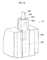
- FIG. 13 It is a perspective view of the sensor head.
- FIG. 14 It is a side view of the press brake (when measuring a work piece).
- FIG. 15 It is a side view for explaining a method for calculating a bent angle of the work piece by the press brake.
- a press brake 1 according to an embodiment will be explained hereinafter with reference to FIG. 1 to FIG. 15 .
- the press brake 1 includes a press brake main body (hereinafter, simply referred as a main body) 1 H, and a stacker 1 TS provided on one side (right side in FIG. 1 ) along a lateral direction of the main body 1 H.
- a press brake main body hereinafter, simply referred as a main body
- a stacker 1 TS provided on one side (right side in FIG. 1 ) along a lateral direction of the main body 1 H.
- the stacker 1 TS exchangeable tools to be exchanged by an after-explained ATC device 40 are stocked.
- the main body 1 H includes a pair of side frames 3 L and 3 R each has an almost C-shaped side view, and a base 5 with which their lower portions are fixed.
- Bottom tool holders 7 (see FIG. 1 : not shown in FIG. 2 ) are provided on a front side (near side in FIG. 1 ) of the base 5 .
- a die station (lower table) 9 is fixed with upper portions of the bottom tool holders 7 .
- a bottom tool (die) 9 T is detachably fixed with the die station 9 .
- a vertically movable ram 15 is provided at an upper portion of the pair of side frames 3 L and 3 R.
- Oil hydraulic cylinders (actuators) 17 L and 17 R are provided on upper both sides of the ram 15 , respectively.
- Piston rods 19 L and 19 R are attached to lower portions of the oil hydraulic cylinders 17 L and 17 R, respectively.
- the ram 15 is supported by the oil hydraulic cylinders 17 L and 17 R with a ball bearing at each lower end of the piston rods 19 L and 19 R interposed therebetween.
- An operation unit 92 has a display 92 a , an operation panel 92 b and a controller 93 . Note that, of course, a touchscreen into which the display 92 a and the operation panel 92 b are integrated may be used.
- a (second) guide rail 37 F for linear movements of an after-explained (second) measurement portion 39 F along a lateral direction (an X-axis direction) is provided on a front face of the base 5 .
- a (first) guide rail 37 R for linear movements of an after explained (first) measurement portion 39 R and an after explained ATC device 40 along the lateral direction is provided on a rear face of the base 5 .
- An end of the guide rail 37 F on the front face is extended at least to an end (a position P 3 in FIG. 1 ) of the die station 9 , and to a right end of the base 5 in the present embodiment.
- Another end of the guide rail 37 F on the front face is extended out to an area outer than another end (a position P 1 in FIG. 1 ) of the die station 9 .
- An end of the guide rail 37 R on the rear face is extended to the stacker ITS. Another end of the guide rail 37 R on the rear face is extended out to the area outer than the other end (the position P 1 ) of the die station 9 .
- the area outer than the position P 1 of the main body 1 H is referred as a measurement portion waiting area AR 1 .
- a section of the main body 1 H outer than the position P 1 is referred as a measurement portion waiting section (first waiting section) AR 1 B.
- an area of the guide rail 37 R outer than the position P 3 is referred as an ATC device waiting area AR 2 .
- a section of the main body 1 H outer than the position P 3 is referred as an ATC device waiting section (second waiting section) AR 2 B.
- the stacker 1 TS is included in the ATC device waiting section AR 2 B.
- a (front) measurement portion 39 F for measuring front dimension of a workpiece is slidably attached to the guide rail 37 F.
- the measurement portion 39 F has a block 38 F, and is coupled with the guide rail 37 F with the block 38 F interposed therebetween.
- a (rear) measurement portion 39 R for measuring rear dimension of the workpiece is slidably attached to the guide rail 37 R.
- the measurement portion 39 R has a block 38 R, and is coupled with the guide rail 37 R with the block 38 R interposed therebetween.
- “LM guide” (trademark owned by THK Co., Ltd.) can be used as pairs of the guide rails 37 F/ 37 R and the blocks 38 F/ 38 R.
- drive units 69 F and 69 R for driving the measurement portions 39 F and 39 R, respectively, are provided on the base 5 .
- the drive units 69 F and 69 R move the measurement portions 39 F and 39 R along the guide rails 37 F and 37 R, respectively, based on commands from the controller 93 .
- the controller 93 controls the measurement portions 39 F and 39 R to move the measurement portions 39 F and 39 R while facing them to each other. Namely, the measurement portions 39 F and 39 R can be moved synchronously with each other.
- the controller 93 can also control the measurement portions 39 F and 39 R to move the measurement portions 39 F and 39 R independently from each other.
- An ATC device 4 for automatically exchanging the dies 9 T is attached to the rear guide rail 37 R slidably along the guide rail 37 R in the lateral direction.
- an ATC drive unit 70 (not shown in FIG. 1 and FIG. 2 ) for driving the ATC device 40 is provided on the base 5 .
- the ATC drive unit 70 moves the ATC device 40 along the guide rail 37 R based on commands from the controller 93 .
- a guide rail (not shown) may be provided on a front or rear side of the punch station 23 and an ATC device (not shown) may be provided slidably on the guide rail.
- the ATC device 40 is attached to the guide rail 37 R on a side of the stacker 1 TS with respect to the measurement portion 39 R. As explained above, only the measurement portion 39 F is supported by the front guide rail 37 F, and the measurement portion 39 F and the ATC device are supported by the rear guide rail 37 R.
- the press brake 1 includes a detection sensors KS.
- the detection sensors KS includes a front sensor 51 for detecting a position of the measurement portion 39 F, a rear sensor 52 for detecting a position of the measurement portion 39 R, an ATC sensor 53 for detecting a position of the ATC device 40 , and a ram sensor 54 for detecting a position of the ram 15 .
- the front sensor 51 continuously detects a lateral position of the measurement portion 39 F on the guide rail 37 F, and outputs a signal SG 1 to the controller 93 as front measurement portion position information.
- the rear sensor 52 continuously detects a lateral position of the measurement portion 39 R on the guide rail 37 R, and outputs a signal SG 2 to the controller 93 as rear measurement portion position information.
- the ATC sensor 53 continuously detects a lateral position of the ATC device 40 on the guide rail 37 R, and outputs a signal SG 3 to the controller 93 as ATC position information.
- the ram sensor 54 continuously detects a vertical position of the ram 15 within a movable range of the ram 15 , and outputs a signal SG 4 to the controller 93 as ram position information.
- the operation panel 92 b outputs a signal SG 5 to the controller 93 based on user's operations.
- the measurement portions 39 F and 39 R detect a bent shape of a workpiece, and outputs signals SG 39 F and SG 39 R to the controller 93 as measurement result information.
- the controller 93 also controls operations of each of the drive units.
- the controller 93 outputs a control signal CS 1 to the ATC drive unit 70 to control movements of the ATC device 40 on the guide rail 37 R.
- the controller 93 outputs control signals CS 2 and CS 3 to the oil hydraulic cylinders 17 L and 17 R to control vertical movements of the ram 15 .
- the controller 93 outputs a control signal CS 4 to the drive unit 69 F to control movements of the measurement portion 39 F on the guide rail 37 F.
- the controller 93 outputs a control signal CS 5 to the drive unit 69 R to control movements of the measurement portion 39 R on the guide rail 37 R.
- the controller 93 outputs a control signal CS 6 to the ATC device 40 to control exchanges of tools by the ATC device 40 .
- the controller 93 outputs a graphic signal SG 6 to the display 92 a to control graphical displays (including movies) on the display 92 a .
- the graphical displays include operational information of the press brake 1 and input information from the operation panel 92 b , for example.
- the ATC device 40 selects an adequate die 9 T from the stacker 1 ST, and carries it to the die station 9 to install it at an adequate place.
- the ATC device 40 After installation of the die 9 T, the ATC device 40 is moved to the ATC device waiting area AR 2 (e.g. in the stacker 1 ST), and, instead, the measurement portion 39 R is moved from the measurement portion waiting area AR 1 to a position (workpiece measurement position) of the installed die 9 T.
- the ATC device waiting area AR 2 e.g. in the stacker 1 ST
- the measurement portion 39 R is moved from the measurement portion waiting area AR 1 to a position (workpiece measurement position) of the installed die 9 T.
- the ram 15 is moved downward to start a bending of a workpiece. Shape changes of the workpiece is continuously measured by the measurement portions 39 F and 39 R, and then the downward movement of the ram 15 is stopped when a desired bent angle determined in consideration of springback is achieved. The ram 15 is held for a given time if necessary, and then moved upward.
- the measurement portion 39 R is moved to the measurement portion waiting area AR 1 , and then the operations are started again from the process of the above 1).
- FIG. 4 movements of the measurement portions 39 R and 39 F moved synchronously are indicated by white circles, and movements of the ATC device 40 are indicated by black circles.
- Fig. 5( a ) to Fig. 5( c ) the measurement portions 39 F and 39 R moved synchronously are shown by only the measurement portion 39 R.
- Fig. 5( a ) to Fig. 5( c ) are views of the press brake 1 viewed from its front side, but show the rear guide rail 37 R to make comparisons with FIG. 1 and FIG. 4 easy.
- each time T 1 to T 9 in the following explanations and FIG. 4 indicates a time point when each duration time T 1 to T 9 elapses from the time T 0 , respectively.
- a state of the press brake 1 at the time T 0 is a base state (state A), and shown in FIG. 5( a ) .
- the measurement portion 39 R ( 39 F) is positioned in the measurement portion waiting area AR 1
- the ATC device 40 is positioned in the ATC device waiting area AR 2 (e.g. in the stacker 1 ST).
- the controller 93 When a user inputs, to the operation panel 92 b , a command for installing a desired tool at the position P 2 on the die station 9 , the controller 93 outputs, to the ATC device 40 and the ATC drive unit 70 , a command DR 1 for picking up the desired tool from the stacker 1 ST and then moving to the position P 2 .
- the ATC device 40 is moved from the stacker 1 TS to the position P 2 by the ATC drive unit 70 based on the command DR 1 .
- the controller 93 judges whether or not the ATC device 40 reaches the position P 2 based on the signal SG 3 from the ATC sensor 53 .
- the controller 93 determines that the ATC device 40 reaches the position P 2 , it outputs, to the ATC device 40 , a command for installing the tool carried to the position P 2 .
- the ACT device 40 installs the tool based on the command.
- a state from time T 1 to T 2 (state B) is shown in FIG. 5( b ) .
- the controller 93 When the controller 93 received, from the ATC device 40 , a signal indicating installation completion of the tool, it outputs, to the ATC drive unit 70 , a command DR 2 for making the ATC device 40 waited in the stacker 1 ST (ATC device waiting area AR 2 ) again.
- the ATC device 40 is moved to the stacker 1 ST by the ATC drive unit 70 to be in a waited state based on the command DR 2 .
- the controller 93 determines that the ACT device 40 reaches the stacker 1 ST based on the signal SG 3 from the ATC sensor 53 , it outputs a command DR 3 , to the drive unit 69 R ( 69 F), for moving the measurement portion 39 R ( 39 F) from the measurement portion waiting area AR 1 to the position P 2 .
- the measurement portion 39 R ( 39 F) is moved to the position P 2 by the drive unit 69 R ( 69 F) based on the command DR 3 .
- the controller 93 judges whether or not the measurement portion 39 R ( 39 F) reaches the position P 2 based on the signal SG 2 (SG 1 ) from the rear sensor 52 (the front sensor 51 ).
- the controller 93 determines that the measurement portion 39 R ( 39 F) reaches the position P 2 , it confirms that a workpiece is placed at an adequate position and then outputs a command for moving the ram 15 downward to the oil hydraulic cylinders 17 L and 17 R.
- the placement confirmation of the workpiece is automatically done by using a sensor, or done by a user's input from the operation panel 92 b to the controller 93 .
- the ram 15 is moved downward based on the move-downward command.
- the controller 93 calculates a bent angle of the workpiece based on the signals SG 39 F and SG 39 R from the measurement portions 39 F and 39 R, and judges whether or not the workpiece is bent to a desired bent angle. A method for calculating a bent angle will be explained later. In this judgment, parameters specific to material such as a springback amount and bending rigidity are taken into consideration.
- the controller 93 determines that the workpiece is bent to the desired bent angle, it stops the downward movement of the ram 15 and holds the ram 15 for a given time if necessary, and then outputs a command for moving the ram 15 upward to the oil hydraulic cylinders 17 L and 17 R.
- the ram 15 is moved upward based on the command.
- a state from time T 4 to T 6 (state C) is shown in FIG. 5( c ) .
- the controller 93 When bendings are completed the desired number of times and another bending(s) will be done at a position Px (not shown) other than the position P 2 , the controller 93 outputs, to the drive unit 69 R ( 69 F), a command for moving the measurement portion 39 R ( 39 F) to the measurement portion waiting area AR 1 .
- the measurement portion 39 R ( 39 F) is moved to the measurement portion waiting area AR 1 by the drive unit 69 R ( 69 F) based on the command.
- the controller 93 judges whether or not the measurement portion 39 R ( 39 F) reaches the measurement portion waiting area AR 1 based on the signal SG 2 (SG 1 ) from the rear sensor 52 (the front sensor 51 ).
- the controller 93 determines that the measurement portion 39 R ( 39 F) reaches the measurement portion waiting area AR 1 based on the signal SG 2 (SG 1 ), the controller 93 outputs, to the ATC device 40 and the ATC drive unit 70 , a command for picking up another tool from the stacker 1 ST and then moving to the position Px.
- the ATC device 40 is moved from the stacker 1 TS to the position Px by the ATC drive unit 70 based on the command.
- operations equivalent to those at-and-after the time T 1 are made. Operations until the time T 9 are shown in FIG. 4 .
- the movement of the ATC device 40 from the time T 2 to T 3 and the movement of the measurement portion 39 R ( 39 F) from the time T 3 to T 4 can be made concurrently or partially overlapped so long as the both are not contacted with each other. Similar operations can be applied to the movement of the measurement portion 39 R ( 39 F) from the time T 7 to T 8 and the movement of the ATC device 40 from the time T 8 to T 9 .
- the measurement portions 39 F and 39 R as a bend measurement device will be explained in detail with reference to FIG. 6 to FIG. 15 .
- the measurement portions 39 F and 39 R continuously or intermittently measure bend states of a front side and a rear side of a workpiece during a bending process of the workpiece, respectively, and then output them to the controller 93 .
- FIG. 6 is a perspective view of the press brake 1 viewed from its rear left side, and shows the measurement portions 39 F and 39 R supported by the guide rails 37 F and 37 R and the ATC device 40 supported by the guide rail 37 R.
- FIG. 6 front, rear, left and right directions identical to those in FIG. 1 are shown.
- FIG. 7 is a side view viewed along an arrow Y 1 in FIG. 6 , and shows components not schematically but realistically.
- FIG. 7 shows a state where the die 9 T is installed on the die station 9 , and the ATC device 40 is not shown in it.
- the guide rail 37 R supports the measurement portion 39 R and the ATC device 40 whose mass is too much larger than that of the measurement portions 39 R. Therefore, the guide rail 37 R has a cross-sectional area larger than a cross-sectional area of the guide rail 37 F, higher-rigidity, and higher-strength, so that it is configured so as to support both of the measurement portion 39 R and the ATC device 40 with no problem.
- the guide rail 37 F and the guide rail 37 R (indicated by hatching in FIG. 7 ) are attached at different height levels from each other.
- the measurement portion 39 F and the measurement portion 39 R are attached to the guide rails 37 F and 37 R that have different shapes and different attached positions from each other by differently-shaped coupling members, respectively. Therefore, the measurement portion 39 F and the measurement portion 39 R can have (first/second) main units 39 that have an identical configuration.
- FIG. 8 shows the front measurement portion 39 F
- FIG. 9 shows the rear measurement portion 39 R
- the measurement portion 39 F is configured of the main unit 39 and a coupling portion 38 FS
- the measurement portion 39 R is configured of the main unit 39 and a coupling portion 38 RS.
- the main units 39 of the measurement portion 39 F and the measurement portion 39 R have an identical configuration
- the coupling portion 38 FS and the coupling portion 38 RS have different configurations from each other.
- the main unit 39 has a protect cover 39 cv , a first fixing portion 39 a that is an attachment reference along a vertical direction, and a second fixing portion 39 b that is an attachment reference along a front-rear direction.
- a position at a bottom face of the first fixing portion 39 a becomes a reference position SF 1 along a vertical direction (also see FIG. 7 ), and a position at a side face of the second fixing portion 39 b becomes a reference position SF 2 along a front-rear direction (see FIG. 7 ).
- the coupling portion 38 FS of the front measurement portion 39 F is configured to have a block 38 F coupled with the guide rail 37 F and an L-shaped bracket 38 Fa.
- the block 38 F is fixed with one side face 38 Fa 1 of the L-shaped bracket 38 Fa.
- a top face 38 Fa 2 of the L-shaped bracket 38 Fa is fixed with the first fixing portion 39 a of the main unit 39 .
- Another side face 38 Fa 3 of the L-shaped bracket 38 Fa is fixed with the second fixing portion 39 b of the main unit 39 .
- the above components are fixed by screws or bolts, for example.
- the coupling portion 38 RS of the rear measurement portion 39 R is configured to have a block 38 R coupled with the guide rail 37 R, a flat plate 38 Ra and a spacer 38 Rb.
- the spacer 38 Rb is configured of a cuboid portion 38 Rb 1 and a flange 38 Rb 2 monolithically extended from the cuboid portion 38 Rb 1 .
- the block 38 R is fixed with one face 38 Ra 1 of the plate 38 Ra.
- a top face 38 Rbt of the spacer 38 Rb is fixed with the first fixing portion 39 a of the main unit 39 .
- Another face 38 Ra 2 of the plate 38 Ra is fixed with the second fixing portion 39 b of the main unit 39 .
- the above components are fixed by screws or bolts, for example.
- the guide rail 37 F and the guide rail 37 R have different shapes from each other, and are attached to the base 5 at asymmetrical positions.
- shapes and dimensions of the coupling portions 38 FS and 38 RS are configured so that the first fixing portions 39 a and the second fixing portions 39 b of the measurement portions 39 F and 39 R are made coincident with the reference positions SF 1 and SF 2 shown in FIG. 7 . Therefore, the measurement portions 39 F and 39 R can commonly use the main units 39 having an identical configuration.
- the measurement portions 39 F and 39 R don't directly measure a bent angle of a workpiece, but measures a shape of workpiece required for calculation of a bent angle by the controller 93 .
- FIG. 10 shows the rear measurement portion 39 R and
- FIG. 11 shows the front measurement portion 39 F, and each of the main units 39 includes an upper base 39 ub including the first fixing portion 39 a , a lower base 39 db including the second fixing portion 39 b , and the protect cover 39 cv for covering the upper base 39 ub and the lower base 39 db.
- the upper base 39 ub and the lower base 39 db are coupled with each other by a metal part(s) such as a frame 39 fr .
- a sensor assembly 49 is attached to the upper base 39 ub .
- the sensor assembly 49 has a sensor head 49 h , an arm 49 a , and an air cylinder 49 b .
- the sensor head 49 h is fixed with an end of the arm 49 a .
- the air cylinder 49 b extends and retracts a rod 49 r (see FIG. 12 ).
- An end of the rod 49 r is fixed with the sensor head 49 h (and with the arm 49 a with the sensor head 49 49 h interposed therebetween).
- the air cylinder 49 b moves the sensor head 49 h by extending and retracting the rod 49 r .
- an operational direction of the air cylinder 49 b (the rod 49 r ) is set oblique to a vertical direction. Namely, the sensor head 49 h and the arm 49 a are moved, by the air cylinder 49 b , linearly and obliquely to a vertical plane including the reference position SF 2 (see FIG. 7 ) of the second fixing portion 39 b .
- FIG. 12 shows a state where the rod 49 r is fully extended.
- most port of the sensor head 49 h is stored in an inside of the protect cover 39 cv (see FIG. 7 ).
- FIG. 13 shows only the sensor head 49 h viewed along an arrow YS 2 in FIG. 12 .
- the sensor head 49 h has a case 49 h 4 , a guide 49 h 2 , a contact element 49 h 1 , and a linear scale 49 h 3 .
- the guide 49 h 2 can be protruded from the case 49 h 4 in a vertical direction.
- the contact element 49 h 1 can be protruded from the guide 49 h 2 in a vertical direction.
- the liner scale 49 h 3 is housed in the case 49 h 4 , and protrudes the contact element 49 h 1 and the guide 49 h 2 independently.
- Part of an end edge of the guide 49 h 2 is formed as a curved end ridge 49 h 5 .
- protrusion directions of the guide 49 h 2 and the contact element 49 h 1 are a vertical direction.
- the controller 93 controls the liner scale 49 h 3 to generate a pressing force enabling both of the end ridge 49 h 5 and the end of the contact element 49 h 1 to be contacted with a surface of a workpiece.
- the pressing force is set as a small force that doesn't affects bending of the workpiece.
- the contact element 49 h 1 is protruded until it is contacted with a surface of the workpiece.
- the guide 49 h 2 is also protruded until the end ridge 49 h 5 is contacted with a surface of the workpiece.
- the contact element 49 h 1 and the guide 49 h 2 can be protruded independently from each other, and their protrusion stroke amounts are measured by the liner scale 49 h 3 separately.
- the liner scale 49 h 3 of the front measurement portion 39 F measures each stroke amount of the contact element 49 h 1 and the guide 49 h 2 , and then outputs the signal SG 39 F (see FIG. 3 ) to the controller 93 as the measurement result information.
- the liner scale 49 h 3 of the rear measurement portion 39 R measures each stroke amount of the contact element 49 h 1 and the guide 49 h 2 , and then outputs the signal SG 39 R (see FIG. 3 ) to the controller 93 as the measurement result information.
- a workpiece 80 is bent by a downward movement of the punch 23 T with its bottom surface supported by the die 9 T.
- the controller 93 extends the rods 49 r of the measurement portions 39 f and 39 R by actuating the air cylinders 49 b to contact the case 49 h 4 with a side face of the die 9 T preliminarily.
- the linear scale(s) 49 h 3 strokes the contact element 49 h 1 and the guide 49 h 2 upward in a vertical direction, and contacts them with the workpiece 80 and urges them toward the workpiece 80 to make them followed with shape changes of a bottom surface of the workpiece 80 .
- the measurement portions 39 F and 39 R continuously output the signals SG 39 F and SG 39 R to the controller 93 .
- the signals SG 39 F and SG 39 R include the measurement result information of a contact point between the contact element 49 h 1 of each of the measurement portions 39 F and 39 R and the workpiece 80 and a contact point between the guide 49 h 2 (the end ridge 49 h 5 ) and the workpiece 80 .
- the controller 93 calculates a bent angle of the workpiece 80 by using the measurement result information of total four points. As shown in FIG. 14 , a distance from the end ridge 49 h 5 to an upper end edge of the contact element 49 h 1 on a side of the end ridge 49 h 5 is a constant value X. In addition, from the measurement result information, a protrusion amount Y 1 and Y 2 of the contact element 49 h 1 from a top face 49 h 6 of the guide 49 h 2 can be calculated from a difference between the stroke amount of the contact element 49 h 1 and the stroke amount of the guide 49 h 2 .
- Front and rear oblique angles ⁇ 1 [°] and ⁇ 2 [°] of the workpiece 80 based on a horizontal line SL can be calculated from following equations.
- ⁇ 1 tan ⁇ 1 ( Y 1 /X )
- ⁇ 2 tan ⁇ 1 ( Y 2 /X )
- the controller 93 continuously monitors changes of the bent angle ⁇ of the workpiece 80 , and stops the ram 15 when a bent angle determined in consideration of springback and so on is achieved so that a bent angle of the workpiece 80 removed from the press brake 1 becomes a desired angle.
- a bent angle of the workpiece 80 is continuously measured by the measurement portions 39 F and 39 R, and operations of the ram 15 is controlled by the controller 93 based on the measurement results.
- Position information of the workpiece 80 to be measured by the measurement portions 39 F and 39 R, position information of the punch 23 T on the punch station 23 and position information of the die 9 T on the die station 9 are previously input into the controller 93 through the operation panel 92 b .
- the punch station 23 may automatically detect an installed position of the punch 23 T and the die station 9 may automatically detect an installed position of the die 9 T, and then the controller 93 may determine the positions based on the detection results.
- the main unit 39 of the measurement portions 39 F and 39 R is a part that carries out the measurements of a shape of the workpiece 80 .
- the coupling portions 38 FS and 38 RS are not a part that carries out the measurements of a shape of the workpiece 80 , but a part that has function of setting a position of the main unit 39 .
- the controller 93 moves the measurement portion 39 R and the ATC device 40 so as not to contact the measurement portion 39 R and the ATC device 40 with each other on the single guide rail 37 R. Therefore, it becomes possible to make the measurement portion 39 R and the ATC device 40 coexistent.
- the main units 39 of the measurement portions 39 F and 39 R can have an identical configuration by coupling the guide rails 37 F and 37 R with the main units 39 of the measurement portions 39 F and 39 R by the coupling portions 38 FS and 38 RS that have different shapes from each other, even when the guide rails 37 F and 37 R have different shapes from each other or even when the guide rails 37 F and 37 R are attached to the base 5 asymmetrically to each other. Therefore, the front measurement portion 39 F and the rear measurement portion 39 R can commonly use the main unit 39 .
- the front measurement portion 39 F and the rear measurement portion 39 R measure the workpiece 80 at symmetrical positions with respect to the die 9 T along all of a front-back direction, a lateral direction and a vertical direction. According to this, a shape of the workpiece 80 can be measured with high accuracy.
- the present embodiment it becomes possible to make the ATC device and the bend measurement device coexistent and make the front and rear measurement portions of the bend measurement device have an identical configuration.
- the measurement portions 39 F and 39 R may be supported by the guide rails 37 F and 37 R at plural positions, respectively.
- the controller 93 controls positions of the plural measurement portions ( 39 F and 39 R) so as not to contact the plural measurement portions ( 39 F and 39 R) with each other.
- the plural measurement portions ( 39 F and 39 R) may measure a shape of the workpiece 80 with no contacts.
- the controller 93 may not be included in the press brake 1 .
- a communication unit is provided in the press brake 1 and the controller 93 is provided in an external device, and the controller 93 communicates with the communication unit by using wired or wireless connection to control the press brake 1 .
Applications Claiming Priority (3)
| Application Number | Priority Date | Filing Date | Title |
|---|---|---|---|
| JP2011126058A JP5759274B2 (ja) | 2011-06-06 | 2011-06-06 | プレスブレーキ及び曲げ加工方法 |
| JP2011-126058 | 2011-06-06 | ||
| PCT/JP2012/064390 WO2012169461A1 (ja) | 2011-06-06 | 2012-06-04 | プレスブレーキ、及び、プレスブレーキを用いた曲げ加工方法 |
Publications (2)
| Publication Number | Publication Date |
|---|---|
| US20140123723A1 US20140123723A1 (en) | 2014-05-08 |
| US9545654B2 true US9545654B2 (en) | 2017-01-17 |
Family
ID=47296024
Family Applications (1)
| Application Number | Title | Priority Date | Filing Date |
|---|---|---|---|
| US14/124,042 Active 2033-10-30 US9545654B2 (en) | 2011-06-06 | 2012-06-04 | Press brake and bending method using press brake |
Country Status (4)
| Country | Link |
|---|---|
| US (1) | US9545654B2 (ja) |
| EP (1) | EP2719476B1 (ja) |
| JP (1) | JP5759274B2 (ja) |
| WO (1) | WO2012169461A1 (ja) |
Cited By (1)
| Publication number | Priority date | Publication date | Assignee | Title |
|---|---|---|---|---|
| CN108115005A (zh) * | 2017-11-23 | 2018-06-05 | 安徽省天坛重工机床制造有限公司 | 一种液压板料数控折弯机的折弯系统 |
Families Citing this family (12)
| Publication number | Priority date | Publication date | Assignee | Title |
|---|---|---|---|---|
| DK2939753T3 (en) | 2014-04-30 | 2017-02-27 | Salvagnini Italia Spa | Plate Bending Machine |
| JP6364321B2 (ja) * | 2014-10-31 | 2018-07-25 | 株式会社アマダホールディングス | ダイ及びダイストッカ |
| DE102014116386A1 (de) | 2014-11-10 | 2016-05-12 | Trumpf Maschinen Austria Gmbh & Co.Kg. | Biegepresse und Beschickungsvorrichtung für eine Biegepresse |
| AT516043B1 (de) | 2014-11-12 | 2016-02-15 | Trumpf Maschinen Austria Gmbh | Biegepresse und Beschickungsvorrichtung für eine Biegepresse |
| JP6408924B2 (ja) * | 2015-02-02 | 2018-10-17 | 株式会社アマダホールディングス | プレスブレーキにおける安全装置取り付け構造及びプレスブレーキ |
| USD807933S1 (en) * | 2015-08-14 | 2018-01-16 | Henri Emil Louis Maurice Zermatten | Tool for a press brake |
| AT518111B1 (de) * | 2015-12-16 | 2017-10-15 | Trumpf Maschinen Austria Gmbh & Co Kg | Biegepresse mit Werkzeugwechselvorrichtung |
| JP6387437B1 (ja) * | 2017-05-24 | 2018-09-05 | 株式会社アマダホールディングス | プレスブレーキ |
| TR201722072A2 (tr) * | 2017-12-27 | 2018-02-21 | Durmazlar Makina Sanayi Ve Ticaret Anonim Sirketi | Cnc büküm maki̇neleri̇ i̇çi̇n otomati̇k takim deği̇şti̇rme si̇stemi̇ |
| DE102018110955A1 (de) | 2018-05-08 | 2019-11-14 | Bystronic Laser Ag | Werkzeugaufbewahrungsvorrichtung für eine Werkzeugmaschine und Werkzeugmaschine |
| JP7329399B2 (ja) * | 2019-09-19 | 2023-08-18 | 株式会社アマダ | 曲げ角度検出ユニット、曲げ角度検出システム及び曲げ角度検出ユニットの実装方法 |
| CN114769373B (zh) * | 2022-05-03 | 2022-09-30 | 泰州俊宇不锈钢材料有限公司 | 一种用于不锈钢制品生产用折弯机构 |
Citations (8)
| Publication number | Priority date | Publication date | Assignee | Title |
|---|---|---|---|---|
| JPH0230326A (ja) | 1988-07-19 | 1990-01-31 | Yamazaki Mazak Corp | ワーク計測手段付きプレスブレーキ及びそのワーク計測方法 |
| EP0470263A1 (en) | 1990-02-23 | 1992-02-12 | Amada Company Limited | Method and apparatus for measuring the angle of work |
| JPH09201623A (ja) | 1996-01-26 | 1997-08-05 | Amada Co Ltd | 板材曲げ加工機における曲げ加工方法及びその曲げ加工方法を適用した板材曲げ加工機 |
| JPH10286627A (ja) | 1997-04-14 | 1998-10-27 | Amada Eng Center:Kk | ワーク傾き角度測定方法およびワーク曲げ角度測定方法並びにワーク傾き量測定装置,ワーク曲げ角度測定装置 |
| JP2000071028A (ja) | 1998-08-28 | 2000-03-07 | Amada Co Ltd | 金型及び金型交換装置 |
| WO2000041824A1 (fr) | 1999-01-13 | 2000-07-20 | Amada Company, Limited | Systeme de presse a cintrer |
| JP2004337950A (ja) | 2003-05-19 | 2004-12-02 | Amada Co Ltd | ベンディングインジケータ配置方法及び曲げ加工装置並びに曲げ加工システム |
| EP1844870A1 (en) | 2004-12-27 | 2007-10-17 | Amada Company, Ltd. | Workpiece bending angle detecting device and workpiece bending machine |
-
2011
- 2011-06-06 JP JP2011126058A patent/JP5759274B2/ja active Active
-
2012
- 2012-06-04 US US14/124,042 patent/US9545654B2/en active Active
- 2012-06-04 WO PCT/JP2012/064390 patent/WO2012169461A1/ja active Application Filing
- 2012-06-04 EP EP12796405.4A patent/EP2719476B1/en active Active
Patent Citations (8)
| Publication number | Priority date | Publication date | Assignee | Title |
|---|---|---|---|---|
| JPH0230326A (ja) | 1988-07-19 | 1990-01-31 | Yamazaki Mazak Corp | ワーク計測手段付きプレスブレーキ及びそのワーク計測方法 |
| EP0470263A1 (en) | 1990-02-23 | 1992-02-12 | Amada Company Limited | Method and apparatus for measuring the angle of work |
| JPH09201623A (ja) | 1996-01-26 | 1997-08-05 | Amada Co Ltd | 板材曲げ加工機における曲げ加工方法及びその曲げ加工方法を適用した板材曲げ加工機 |
| JPH10286627A (ja) | 1997-04-14 | 1998-10-27 | Amada Eng Center:Kk | ワーク傾き角度測定方法およびワーク曲げ角度測定方法並びにワーク傾き量測定装置,ワーク曲げ角度測定装置 |
| JP2000071028A (ja) | 1998-08-28 | 2000-03-07 | Amada Co Ltd | 金型及び金型交換装置 |
| WO2000041824A1 (fr) | 1999-01-13 | 2000-07-20 | Amada Company, Limited | Systeme de presse a cintrer |
| JP2004337950A (ja) | 2003-05-19 | 2004-12-02 | Amada Co Ltd | ベンディングインジケータ配置方法及び曲げ加工装置並びに曲げ加工システム |
| EP1844870A1 (en) | 2004-12-27 | 2007-10-17 | Amada Company, Ltd. | Workpiece bending angle detecting device and workpiece bending machine |
Non-Patent Citations (2)
| Title |
|---|
| International Search Report, mail date is Aug. 21, 2012. |
| Search report from E.P.O., mail date is Feb. 11, 2015. |
Cited By (1)
| Publication number | Priority date | Publication date | Assignee | Title |
|---|---|---|---|---|
| CN108115005A (zh) * | 2017-11-23 | 2018-06-05 | 安徽省天坛重工机床制造有限公司 | 一种液压板料数控折弯机的折弯系统 |
Also Published As
| Publication number | Publication date |
|---|---|
| EP2719476A1 (en) | 2014-04-16 |
| EP2719476B1 (en) | 2015-12-16 |
| WO2012169461A1 (ja) | 2012-12-13 |
| JP2012250270A (ja) | 2012-12-20 |
| JP5759274B2 (ja) | 2015-08-05 |
| US20140123723A1 (en) | 2014-05-08 |
| EP2719476A4 (en) | 2015-03-11 |
Similar Documents
| Publication | Publication Date | Title |
|---|---|---|
| US9545654B2 (en) | Press brake and bending method using press brake | |
| KR20210143256A (ko) | Crtsⅲ형 궤도판 고속 지능화 정밀 조정 시스템 및 정밀 조정 방법 | |
| CN105013884A (zh) | 高精度液压折弯机 | |
| CN114289556B (zh) | 一种钢构件矫正装置 | |
| CN205032505U (zh) | 高精度液压折弯机 | |
| US20130340494A1 (en) | Procedure for the dynamic correction of the bending angle of sheet metal on a panel bender machine | |
| JP4094916B2 (ja) | 曲げ加工装置 | |
| CN205271182U (zh) | 一种电池端子焊接装置 | |
| JP2019081184A (ja) | 曲げ加工方法及び曲げ加工システム | |
| CN114440797A (zh) | 一种适用于全路段钢轨校直检测装置及方法 | |
| CN204694224U (zh) | 一种壳体深度测量装置 | |
| KR101299280B1 (ko) | 가공성 평가용 봉강 고정장치 | |
| CN114178495A (zh) | 一种连铸结晶器对中自动检测装置及其使用方法 | |
| CN111766135A (zh) | 一种用于测试防静电活动地板滚动荷载的试验装置及方法 | |
| CN209432101U (zh) | 一种用于轴类零件自动矫直设备的同轴度检测装置 | |
| CN206300786U (zh) | 一种多轴自动按压力试验机 | |
| US20220097261A1 (en) | Teaching method for system for taking out molded product and system for taking out molded product | |
| CN211803131U (zh) | 一种蒙皮拉伸装置和蒙皮拉伸设备 | |
| CN214724368U (zh) | 一种机器人抓手停放支架装置 | |
| CN205341723U (zh) | 带激光辅助定位的模具 | |
| CN217110839U (zh) | 一种适用于全路段钢轨校直检测装置 | |
| CN212621852U (zh) | 一种用于测试防静电活动地板滚动荷载的试验装置 | |
| CN219443306U (zh) | 一种便于定位的锻压床 | |
| CN220591180U (zh) | 一种金属板弯折辅助装置及其控制系统 | |
| CN216027329U (zh) | 一种数控液压折弯机的补偿机构 |
Legal Events
| Date | Code | Title | Description |
|---|---|---|---|
| AS | Assignment |
Owner name: AMADA COMPANY, LIMITED, JAPAN Free format text: ASSIGNMENT OF ASSIGNORS INTEREST;ASSIGNOR:YOSHIDA, HIDEHIKO;REEL/FRAME:031723/0056 Effective date: 20131024 |
|
| STCF | Information on status: patent grant |
Free format text: PATENTED CASE |
|
| MAFP | Maintenance fee payment |
Free format text: PAYMENT OF MAINTENANCE FEE, 4TH YEAR, LARGE ENTITY (ORIGINAL EVENT CODE: M1551); ENTITY STATUS OF PATENT OWNER: LARGE ENTITY Year of fee payment: 4 |