US9511900B2 - Self-stabilizing partition wall with enhanced thermal insulation for negative-pressure tanks - Google Patents
Self-stabilizing partition wall with enhanced thermal insulation for negative-pressure tanks Download PDFInfo
- Publication number
- US9511900B2 US9511900B2 US13/696,077 US201113696077A US9511900B2 US 9511900 B2 US9511900 B2 US 9511900B2 US 201113696077 A US201113696077 A US 201113696077A US 9511900 B2 US9511900 B2 US 9511900B2
- Authority
- US
- United States
- Prior art keywords
- partition
- pressure
- negative
- chambers
- walls
- Prior art date
- Legal status (The legal status is an assumption and is not a legal conclusion. Google has not performed a legal analysis and makes no representation as to the accuracy of the status listed.)
- Active, expires
Links
Images


Classifications
-
- B—PERFORMING OPERATIONS; TRANSPORTING
- B65—CONVEYING; PACKING; STORING; HANDLING THIN OR FILAMENTARY MATERIAL
- B65D—CONTAINERS FOR STORAGE OR TRANSPORT OF ARTICLES OR MATERIALS, e.g. BAGS, BARRELS, BOTTLES, BOXES, CANS, CARTONS, CRATES, DRUMS, JARS, TANKS, HOPPERS, FORWARDING CONTAINERS; ACCESSORIES, CLOSURES, OR FITTINGS THEREFOR; PACKAGING ELEMENTS; PACKAGES
- B65D3/00—Rigid or semi-rigid containers having bodies or peripheral walls of curved or partially-curved cross-section made by winding or bending paper without folding along defined lines
- B65D3/02—Rigid or semi-rigid containers having bodies or peripheral walls of curved or partially-curved cross-section made by winding or bending paper without folding along defined lines characterised by shape
- B65D3/06—Rigid or semi-rigid containers having bodies or peripheral walls of curved or partially-curved cross-section made by winding or bending paper without folding along defined lines characterised by shape essentially conical or frusto-conical
-
- B—PERFORMING OPERATIONS; TRANSPORTING
- B65—CONVEYING; PACKING; STORING; HANDLING THIN OR FILAMENTARY MATERIAL
- B65D—CONTAINERS FOR STORAGE OR TRANSPORT OF ARTICLES OR MATERIALS, e.g. BAGS, BARRELS, BOTTLES, BOXES, CANS, CARTONS, CRATES, DRUMS, JARS, TANKS, HOPPERS, FORWARDING CONTAINERS; ACCESSORIES, CLOSURES, OR FITTINGS THEREFOR; PACKAGING ELEMENTS; PACKAGES
- B65D25/00—Details of other kinds or types of rigid or semi-rigid containers
- B65D25/02—Internal fittings
- B65D25/04—Partitions
-
- B—PERFORMING OPERATIONS; TRANSPORTING
- B65—CONVEYING; PACKING; STORING; HANDLING THIN OR FILAMENTARY MATERIAL
- B65D—CONTAINERS FOR STORAGE OR TRANSPORT OF ARTICLES OR MATERIALS, e.g. BAGS, BARRELS, BOTTLES, BOXES, CANS, CARTONS, CRATES, DRUMS, JARS, TANKS, HOPPERS, FORWARDING CONTAINERS; ACCESSORIES, CLOSURES, OR FITTINGS THEREFOR; PACKAGING ELEMENTS; PACKAGES
- B65D3/00—Rigid or semi-rigid containers having bodies or peripheral walls of curved or partially-curved cross-section made by winding or bending paper without folding along defined lines
- B65D3/28—Other details of walls
- B65D3/30—Local reinforcements, e.g. metallic rims
-
- F—MECHANICAL ENGINEERING; LIGHTING; HEATING; WEAPONS; BLASTING
- F25—REFRIGERATION OR COOLING; COMBINED HEATING AND REFRIGERATION SYSTEMS; HEAT PUMP SYSTEMS; MANUFACTURE OR STORAGE OF ICE; LIQUEFACTION SOLIDIFICATION OF GASES
- F25B—REFRIGERATION MACHINES, PLANTS OR SYSTEMS; COMBINED HEATING AND REFRIGERATION SYSTEMS; HEAT PUMP SYSTEMS
- F25B15/00—Sorption machines, plants or systems, operating continuously, e.g. absorption type
-
- F—MECHANICAL ENGINEERING; LIGHTING; HEATING; WEAPONS; BLASTING
- F25—REFRIGERATION OR COOLING; COMBINED HEATING AND REFRIGERATION SYSTEMS; HEAT PUMP SYSTEMS; MANUFACTURE OR STORAGE OF ICE; LIQUEFACTION SOLIDIFICATION OF GASES
- F25B—REFRIGERATION MACHINES, PLANTS OR SYSTEMS; COMBINED HEATING AND REFRIGERATION SYSTEMS; HEAT PUMP SYSTEMS
- F25B17/00—Sorption machines, plants or systems, operating intermittently, e.g. absorption or adsorption type
- F25B17/08—Sorption machines, plants or systems, operating intermittently, e.g. absorption or adsorption type the absorbent or adsorbent being a solid, e.g. salt
-
- F—MECHANICAL ENGINEERING; LIGHTING; HEATING; WEAPONS; BLASTING
- F25—REFRIGERATION OR COOLING; COMBINED HEATING AND REFRIGERATION SYSTEMS; HEAT PUMP SYSTEMS; MANUFACTURE OR STORAGE OF ICE; LIQUEFACTION SOLIDIFICATION OF GASES
- F25B—REFRIGERATION MACHINES, PLANTS OR SYSTEMS; COMBINED HEATING AND REFRIGERATION SYSTEMS; HEAT PUMP SYSTEMS
- F25B35/00—Boiler-absorbers, i.e. boilers usable for absorption or adsorption
- F25B35/04—Boiler-absorbers, i.e. boilers usable for absorption or adsorption using a solid as sorbent
-
- B—PERFORMING OPERATIONS; TRANSPORTING
- B65—CONVEYING; PACKING; STORING; HANDLING THIN OR FILAMENTARY MATERIAL
- B65D—CONTAINERS FOR STORAGE OR TRANSPORT OF ARTICLES OR MATERIALS, e.g. BAGS, BARRELS, BOTTLES, BOXES, CANS, CARTONS, CRATES, DRUMS, JARS, TANKS, HOPPERS, FORWARDING CONTAINERS; ACCESSORIES, CLOSURES, OR FITTINGS THEREFOR; PACKAGING ELEMENTS; PACKAGES
- B65D77/00—Packages formed by enclosing articles or materials in preformed containers, e.g. boxes, cartons, sacks or bags
- B65D77/04—Articles or materials enclosed in two or more containers disposed one within another
- B65D77/048—Articles or materials enclosed in two or more containers disposed one within another the inner and outer containers being rigid and the outer container being of curved cross-section, e.g. cylindrical
- B65D77/0486—Articles or materials enclosed in two or more containers disposed one within another the inner and outer containers being rigid and the outer container being of curved cross-section, e.g. cylindrical the inner container being coaxially disposed within the outer container
-
- Y—GENERAL TAGGING OF NEW TECHNOLOGICAL DEVELOPMENTS; GENERAL TAGGING OF CROSS-SECTIONAL TECHNOLOGIES SPANNING OVER SEVERAL SECTIONS OF THE IPC; TECHNICAL SUBJECTS COVERED BY FORMER USPC CROSS-REFERENCE ART COLLECTIONS [XRACs] AND DIGESTS
- Y02—TECHNOLOGIES OR APPLICATIONS FOR MITIGATION OR ADAPTATION AGAINST CLIMATE CHANGE
- Y02A—TECHNOLOGIES FOR ADAPTATION TO CLIMATE CHANGE
- Y02A30/00—Adapting or protecting infrastructure or their operation
- Y02A30/27—Relating to heating, ventilation or air conditioning [HVAC] technologies
-
- Y—GENERAL TAGGING OF NEW TECHNOLOGICAL DEVELOPMENTS; GENERAL TAGGING OF CROSS-SECTIONAL TECHNOLOGIES SPANNING OVER SEVERAL SECTIONS OF THE IPC; TECHNICAL SUBJECTS COVERED BY FORMER USPC CROSS-REFERENCE ART COLLECTIONS [XRACs] AND DIGESTS
- Y02—TECHNOLOGIES OR APPLICATIONS FOR MITIGATION OR ADAPTATION AGAINST CLIMATE CHANGE
- Y02B—CLIMATE CHANGE MITIGATION TECHNOLOGIES RELATED TO BUILDINGS, e.g. HOUSING, HOUSE APPLIANCES OR RELATED END-USER APPLICATIONS
- Y02B30/00—Energy efficient heating, ventilation or air conditioning [HVAC]
- Y02B30/62—Absorption based systems
-
- Y02B30/64—
-
- Y—GENERAL TAGGING OF NEW TECHNOLOGICAL DEVELOPMENTS; GENERAL TAGGING OF CROSS-SECTIONAL TECHNOLOGIES SPANNING OVER SEVERAL SECTIONS OF THE IPC; TECHNICAL SUBJECTS COVERED BY FORMER USPC CROSS-REFERENCE ART COLLECTIONS [XRACs] AND DIGESTS
- Y10—TECHNICAL SUBJECTS COVERED BY FORMER USPC
- Y10T—TECHNICAL SUBJECTS COVERED BY FORMER US CLASSIFICATION
- Y10T29/00—Metal working
- Y10T29/49—Method of mechanical manufacture
- Y10T29/49826—Assembling or joining
Definitions
- the invention relates to a negative-pressure tank having a partition, the partition including at least two walls, and the negative-pressure tank including at least two chambers, and a free space being present in the partition in which an ambient pressure prevails.
- the invention further relates to a sorption machine having a negative-pressure tank.
- refrigerating machines are described which are generally used for heating and/or cooling buildings.
- Refrigerating machines implement thermodynamic cyclic processes in which, for example, heat is taken in below ambient temperature and released at a higher temperature.
- the thermodynamic cyclic processes resemble those of a heat pump.
- refrigerating machines known in the prior art include adsorption refrigerating units, diffusion-absorption refrigerating machines, adsorption refrigerating units, and solid sorption heat pumps, as well as compression refrigerating units.
- the adsorption refrigerating machine is composed of at least one adsorber/desorber unit, an evaporator, a condenser, and/or a combined evaporator/condenser unit which are housed in the same tank or in separate tanks, in which case the tanks are connected to one another via tubes or the like for the refrigerant flow.
- the advantage of sorption machines over conventional heat pump technology is that the adsorption/desorption process occurs solely via temperature control of the sorbent.
- the tank of the adsorption machine may thus be hermetically sealed in a gas-tight manner.
- the adsorption refrigerating machine preferably operates in the negative pressure range.
- the adsorption which takes place in an adsorption machine describes a physical process in which a gaseous refrigerant (water, for example) accumulates on a solid.
- the desorption of the refrigerant i.e., the release of the refrigerant from the solid, in turn requires energy.
- the refrigerant which takes in heat at low temperature and low pressure and releases heat at higher temperature and higher pressure, is selected in such a way that the adsorption or desorption is accompanied by a change in the state of aggregation.
- Materials which are finely porous and which therefore have a very large internal surface are described in the prior art as adsorbents.
- Advantageous materials are active carbon, zeolites, alumina or silica gel, aluminum phosphates, silica-aluminum phosphates, metal silica-aluminum phosphates, mesostructure silicates, organometallic structures, and/or microporous material, including microporous polymers.
- the heat of adsorption and the heat of condensation must be discharged from the unit. This generally occurs via a flowing heat transfer medium which transports this heat to a heat sink, for example to a recooling plant, which releases the heat to the ambient air.
- a heat sink for example to a recooling plant
- the temperatures, and thus the pressures, inside the adsorption machine would rise, and the adsorption process would come to a standstill.
- the efficiency of an adsorption machine may thus be significantly increased by improved heat transfer, which necessarily also improves the cost-effectiveness of the unit.
- the evaporation in sorption machines generally requires a vacuum tank, since water, for example, may be used as refrigerant, and therefore low pressures are necessary.
- the known classical vacuum tanks have a main body which is usually cylindrical, and which is formed, among other things, by a shell made of metal having a thickness of at least 4 or 5 mm. These types of vacuum tanks are very heavy compared to other parts of sorption machines. The interior components in these vacuum tanks often have a rectangular shape. For these reasons, effective use is often not made of the space provided by the vacuum tank. This is disadvantageous not only for the power density and the material costs, but also for the thermal mass.
- Pressure tanks are described in the prior art whose internal pressure is above or below ambient pressure. To withstand the pressures that occur, the tanks have thick walls, for example, which are also associated with a high base weight. In addition, the manufacturing costs for the pressure tanks are high due to the dimensions of the tank and the material costs. When the pressure tank is used in a sorption machine, the tank must also be thermally insulated. This requires a separate, additional level of effort (for example, insulating elements made of insulating material).
- the object of the invention is to provide a tank which does not have the disadvantages and deficiencies of the prior art, which has a low weight, withstands pressures that occur, has improved thermal insulation between the chambers, and represents reduced thermal masses for the adsorption processes.
- a negative-pressure tank having at least one partition is provided, the partition including at least two walls, and the negative-pressure tank including at least two chambers, wherein the partition separates the chambers, the two walls of the partition are connected to one another, and at least one free space is present in the partition.
- the negative-pressure tank according to the invention does not have the disadvantages and deficiencies of the prior art. Due to the surprising design of the partitions, a light but pressure-resistant negative-pressure tank is provided. In addition, the tank requires less maintenance than the tanks disclosed in the prior art, since the partitions are inherently stable (self-stabilizing) and are not damaged by the pressure forces.
- the tank has improved thermal insulation between the chambers.
- the use of an additional insulating layer which, for example, may be applied to a partition, may thus be dispensed with.
- the insulating layers may be damaged by the high temperatures and pressures, so that frequent maintenance intervals are necessary. When damage occurs, the entire negative-pressure tank must be replaced, which in turn involves a large expenditure of effort and high costs. In the case of the negative-pressure tank according to the invention this is not necessary, since additional insulating layers may be dispensed with entirely.
- One or more partitions may be present in the negative-pressure tank, and one or more chambers may be integrated into the negative-pressure tank.
- the partition may preferably be used to separate at least two chambers of a negative-pressure tank, the partition including at least two walls which are connected to one another at at least one point, at least two free spaces being present in the partition.
- the partition forms a mechanical structure which results from a connection of the two walls of the partition at at least one point, the two walls of the partition enclosing at least two free spaces.
- the free spaces preferably result from the connection of the two walls at at least one point.
- the free spaces are preferably hermetically sealed with respect to the chambers, a gas mixture, preferably air, preferably being present in the free spaces, and an ambient pressure prevailing.
- the ambient pressure is preferably higher than the pressure that is present in the chambers. However, it may also be preferred that the ambient pressure in the free spaces is the same as that in the chambers. Light, stable tanks may thus be provided.
- the partition is embodied by a mechanical structure which has a higher interior pressure level than the negative-pressure chambers themselves.
- the partition has two walls which are partially connected, so that a free space is present in the partition.
- a free space in particular is a space that results from two lateral surfaces or walls of a partition being connected to one another. That is, the free space is present between the walls of the partition. No components or other devices are situated in the free space (also see FIG. 3 , free space (reference numeral 3 )).
- An ambient pressure i.e., an atmospheric pressure
- an atmospheric pressure is preferably present in the free space.
- the atmospheric pressure varies as a function of temperature, elevation, and location. Means are available to one skilled in the art which allow pressure measurement, so that it may be easily determined that a pressure is present in the partition which is different from that in the chambers.
- a pressure in the partition is preferably significantly higher than that in at least one chamber.
- the pressure in the free spaces in the partition is preferably greater than or equal to the pressure that is present in the chambers.
- the chambers may have different pressures, which are preferably different from the pressure that is present in the partition or free space.
- the partition experiences a deformation, so that the volume of the free space increases. Due to the negative pressure in the chambers a very rigid structure is formed in the partition, which in addition results in very good thermal insulation between the chambers (the insulating effect from stationary gas, for example air, results in no heat conduction or convection).
- the pressure of the partition preferably corresponds to ambient pressure.
- the wording “essentially” does not represent ambiguous wording with respect to the pressure, since he recognizes from the overall disclosure of the teaching according to the invention that the pressure in the free spaces of the partition is preferably different from that in the chambers, and this wording naturally encompasses small and large pressure differences alike.
- the differing pressures are determinable, for example, using measuring methods described in the prior art.
- a fluid is present in the free space.
- a fluid refers in particular to a gas or a liquid. It is preferred that air is present in the free space.
- air refers in particular to the gas mixture of the earth's atmosphere. Dry air contains nitrogen, oxygen, argon, carbon dioxide, hydrogen, and other trace gases. It has surprisingly been shown that the negative-pressure tank has fewer natural oscillations, and therefore requires less maintenance.
- the walls of the partition are preferably designed as metal sheets.
- the teaching according to the invention allows thick sheets (thickness less than 3 mm) or also thin sheets to be used for constructing partitions.
- Thin sheets are sheets having a thickness of less than 2 mm, or preferably less than 1 mm. This preferably involves finished hot- or cold-rolled sheet metal, which is primarily used for forming purposes. Depending on the steel grade, these thin sheets may also be tin-plated, zinc-plated, copper-plated, nickel-plated, lacquered, enameled, or coated with a plastic surface coating. It has surprisingly been found that, in particular by use of sheet metal, a thin and therefore light partition or a negative-pressure tank having a low weight may be produced. This sheet metal is thus also usable in machines which previously were not suited for a negative-pressure tank, since the tanks disclosed in the prior art have excessive weight.
- walls refer in particular to two lateral surfaces of the partition which flatly abut one another.
- the walls preferably have a thickness of less than 3 mm, particularly preferably less than 2 mm, and very particularly preferably less than 1 mm.
- Thin-walled partitions may thus be provided which are able to withstand high pressure forces despite a low weight. Partitions having such small wall thicknesses are particularly advantageous, since they are very light but are still able to withstand the mechanical stresses from the vacuum forces.
- the thickness may also relate to only a portion of the walls, so that the wall has areas of different thickness. It has been shown that by use of the preferred wall thicknesses, a negative-pressure tank may be provided which operates with lower noise.
- the partition is preferably used to separate at least two chambers in a pressure tank, in particular a negative-pressure tank.
- a pressure tank in particular a negative-pressure tank.
- the partition analogously represents a hermetic barrier which divides a space in the pressure tank into at least two chambers.
- a negative pressure i.e., a pressure that is lower than ambient pressure, preferably prevails in the chambers. It was completely unexpected that a deformation of the partition could be produced by applying the negative pressure. The deformation may also be achieved, for example, by applying a positive pressure in the partition.
- partitions for negative-pressure tanks may be provided which are deformed in a calculated manner under the forces of the vacuum and are still fully operational.
- the calculated deformation means that, although the partitions are implosion-resistant, they undergo distinct deformation under the action of negative pressure.
- a person with average skills in the art has heretofore assumed that these types of partitions cannot be used in negative-pressure tanks.
- These types of partitions have not been previously used for the mentioned application, since experts in the field presumed that they were unstable and unsafe.
- the walls of the partition are preferably connected to one another in a positive-fit and/or an integrally joined manner.
- a partial connection refers in particular to a connection of the walls which is not present over the entire surface.
- the walls are joined together at their side edges, on their surface there is only at least a punctiform or linear connection. That is, a free space is preferably present between the side walls of the partition. Due to the preferred connection of the walls, the natural oscillation of the partitions may be significantly reduced, so that losses in functionality no longer occur.
- the partition is not to be regarded as a multichamber system. There is only a partial connection between the walls, so that multiple chambers are not generated, but, rather, only a free space.
- the application of a negative pressure results in a deformation of the partition, so that the free space has different volumes before and after the application of the pressure.
- Positive-fit connections preferably result from the interlocking of at least two connection partners.
- the positive-fit connections include screws, rivets, pins, or clamps.
- the walls of the partition may be connected by means of screws, for example, which connect the surfaces at specific points.
- the walls may be connected via integrally joining means.
- Integrally joined connections are held together by atomic or molecular forces. At the same time, they are nondetachable connections which may be loosened only by destroying the components and/or the connection means. Integrally joined connections include soldering, welding, or gluing.
- positive-fit or integrally joined connections may be designed, for example, as weld joints in the form of one or more connecting points (a welding point, for example), or as a linear connection (a weld seam, for example) or a full-surface connection.
- connecting points a welding point, for example
- linear connection a weld seam, for example
- full-surface connection a weld seam, for example
- the partition may have at least one leadthrough or opening for a flow between the chambers.
- This may be, for example, a steam flap or steam valve.
- the vapor openings may advantageously be introduced into the partition at a welding point and allow the steam to flow through.
- the term “flow” refers to an energy transfer and/or mass transfer which occur(s) in particular due to diffusion or convection.
- it may also be advantageous to integrate one or more vapor openings at another location in the partition. The vapor openings may be integrated into the partition in such a way that an optimum vapor exchange may occur between the chambers.
- the joined metal sheets have a different material composition and/or different dimensioning, such as a different thickness.
- the partitions may be composed of various metal sheets having different characteristics, whereby “characteristics” may mean different metal compositions, different dimensioning of the metal sheets, or a different surface treatment or some other type of chemical or physical treatment of the metal sheets and/or the reinforcing means. Partitions or negative-pressure tanks may thus be provided which are insensitive to high temperatures or pressures and have a longer service life.
- the invention likewise relates to a sorption machine comprising a negative-pressure tank which includes at least one partition and at least two chambers, wherein the partition separates the chambers, and the two walls of the partition are preferably connected to one another at at least one point, wherein at least one free space is present in the partition, and an ambient pressure is present in the free space.
- the free space may thus also be referred to as an air chamber.
- the sorption machine is advantageously an adsorption machine, in particular an adsorption refrigerating machine.
- “chambers” preferably describe adsorption chambers and desorption chambers, evaporation chambers, and condensation chambers.
- the partition is advantageously used as a separating wall between the chambers.
- a negative-pressure tank may be cost-effectively manufactured (in a mass production process) which is light, withstands high pressures, and is easily integratable as an essentially maintenance-free component into a sorption machine.
- the weight of a sorption machine may thus be substantially reduced, which in particular significantly improves the usability of the sorption machine.
- the invention further relates to a sorption machine, comprising at least one adsorber-desorber unit having heat exchangers and sorption material, at least one condenser, at least one condenser-heat exchanger, at least one evaporator-condenser unit, and/or an evaporator-heat exchanger, at least a portion of these units being situated in a negative-pressure tank according to the invention, and the sorption machine having terminal and connection elements as well as pipe leadthroughs for hydraulic connections and operation.
- a sorption machine comprising at least one adsorber-desorber unit having heat exchangers and sorption material, at least one condenser, at least one condenser-heat exchanger, at least one evaporator-condenser unit, and/or an evaporator-heat exchanger, at least a portion of these units being situated in a negative-pressure tank according to the invention, and the sorption machine having terminal and connection elements as well as pipe leadthroughs for hydraulic connections and operation.
- the adsorber-desorber unit is present in the negative-pressure tank, the condenser-heat exchanger and the evaporator-heat exchanger being situated at a distance from one another, and the negative-pressure tank with the adsorber-desorber unit being provided in the space between same.
- the dividing surfaces of the negative-pressure tank facing the condenser-heat exchanger and the evaporator-heat exchanger, as well as the partition between the adsorber chamber and the desorber chamber, is/are provided with a partition of the type described above.
- the invention further relates to the use of the negative-pressure tank according to the invention for sorption machines, in particular adsorption refrigerating machines.
- units are situated in the negative-pressure tank according to the invention, whereby the units may be an adsorber-desorber unit, a condenser, an evaporator, a condenser-evaporator unit or an evaporator-condenser unit, an evaporator-heat exchanger, and/or an evaporator-condenser unit, for example.
- operating points may denote certain points in the characteristic map or on the characteristic curve of a technical device, preferably a sorption machine, particularly preferably an adsorption refrigerating machine or adsorption heat machine, which are included due to the system properties and acting external influences and parameters. Examples are the temperatures of the heat sinks, and sources or total volumetric flows in the return cooling circuit in the evaporator or the desorber train.
- the “operating method” preferably refers to the manner in which the machine is operated.
- An example of such is the adaptation of the cycle times of the sorption machine; i.e., the output of the machine may be increased by short cycle times, whereas longer cycle times result in a higher efficiency.
- the installed components may refer, for example, to adsorber heat exchangers, which are provided with the same pressure but with different adsorption material.
- the adsorption material may advantageously be applied differently; i.e., pouring, bonding, and/or crystallization may be involved.
- the adsorption machine may be adapted to different requirements.
- the machine may be adapted to the location or to the refrigerant.
- the layer thickness of the adsorption material is crucial for the performance of the adsorption material.
- the system configuration preferably refers to the configuration of the machine, i.e., for example the internal hydraulic connection of the components of the machine, the internal refrigerant-side connection of the components, or the modified basic design of the machine (for example, the number of adsorbers, operation of the evaporator or of the condenser, etc.).
- the negative-pressure tank may advantageously be used for one-chamber systems, or also for two- or multichamber systems, in each case with only one adsorber or multiple adsorbers of a sorption machine, for example an adsorption machine.
- adaptation may be easily and quickly made to other types of sorption machines. There is essentially no need to change the equipment of the machines for this purpose.
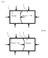
- FIGS. 1 and 2 show variants of the prior art
- FIGS. 3A and 3B show negative-pressure tanks before and after the evacuation
- FIG. 4 shows a negative-pressure tank according to the prior art in a sorption machine
- FIG. 5 shows a preferred negative-pressure tank in a sorption machine
- FIG. 1 and FIG. 2 show one variant of the prior art.
- a negative-pressure tank is illustrated which has two chambers 2 that are separated from one another by a separating wall 1 .
- This wall 1 which is not to be referred to as a partition according to the invention, is generally not subjected to high pressure forces (indicated by black block arrows), since the forces compensate one another. If a higher pressure (p chamber + ⁇ p) is present in one of the chambers 2 than in the other chamber (p chamber ), this results in a deformation of the separating wall 1 . This causes damage to the negative-pressure tank, and may result in rupture of the separating wall 1 . Accordingly, partitions not according to the invention must be thick-walled and heavy, or be provided with reinforcing means in order to avoid the deformations. This generally results in poor thermal insulation between the chambers, and an undesirable increased thermal mass of the tank.
- FIGS. 3A and 3B show a negative-pressure tank according to the invention, before and after the evacuation.
- a negative-pressure tank having two chambers 2 and a partition 1 having two walls 1 . 1 , 1 . 2 , and a connection 4 are illustrated before and after the evacuation.
- the chamber 2 Before the evacuation, the chamber 2 has a pressure that is essentially identical to the pressure of the partition 1 and of the surroundings.
- the pressure in the free space 3 and at the partition 1 is higher than in the chambers 2 .
- the application of pressure has caused the partition 1 to deform, and the volume of the partition 1 and of the free space 3 is increased.
- FIG. 4 shows a negative-pressure tank according to the prior art in a sorption machine.
- the partitions 1 in a sorption machine separate the various components of a sorption machine from one another.
- the sorption machine may have a desorber/adsorber unit 10 , a condenser 6 , and an evaporator 7 , for example.
- the desorber/adsorber unit preferably has two chambers 2 .
- FIG. 5 shows a preferred negative-pressure tank in a sorption machine.
- the illustrated sorption machine has a design which is analogous to the sorption machine illustrated in FIG. 4 .
- a preferred negative-pressure tank is integrated into the sorption machine, the partitions 1 having two walls 1 . 1 , 1 . 2 which are joined to a connection 4 , so that a free space 3 is present between the walls 1 . 1 , 1 . 2 .
- the free space 3 may also be referred to as an air space.
- the pressure in the partition 1 preferably corresponds to ambient pressure, and is therefore higher than the pressure that is present in the components (example: p ambient >>p desorber ⁇ p condenser >p evaporator ⁇ p adsorber ).
- the volume of the free space 3 or of the partition 1 may be increased due to the deformation.
- vapor openings may be introduced into the partitions, so that, for example, a vapor may flow from one chamber 2 into the other. However, the vapor openings do not influence the improved functionality of the characteristic of the deformation of the partition 1 .
Landscapes
- Engineering & Computer Science (AREA)
- Mechanical Engineering (AREA)
- Physics & Mathematics (AREA)
- Thermal Sciences (AREA)
- General Engineering & Computer Science (AREA)
- Filling Or Discharging Of Gas Storage Vessels (AREA)
- Sorption Type Refrigeration Machines (AREA)
- Respiratory Apparatuses And Protective Means (AREA)
- Separation Of Gases By Adsorption (AREA)
Applications Claiming Priority (4)
| Application Number | Priority Date | Filing Date | Title |
|---|---|---|---|
| DE102010019907 | 2010-05-05 | ||
| DE102010019907.9 | 2010-05-05 | ||
| DE102010019907 | 2010-05-05 | ||
| PCT/DE2011/075099 WO2012000494A2 (de) | 2010-05-05 | 2011-05-05 | Selbststabilisierende trennwand mit erhöhter thermischer isolation für unterdruckbehälter |
Publications (2)
| Publication Number | Publication Date |
|---|---|
| US20130133360A1 US20130133360A1 (en) | 2013-05-30 |
| US9511900B2 true US9511900B2 (en) | 2016-12-06 |
Family
ID=44630154
Family Applications (1)
| Application Number | Title | Priority Date | Filing Date |
|---|---|---|---|
| US13/696,077 Active 2034-04-06 US9511900B2 (en) | 2010-05-05 | 2011-05-05 | Self-stabilizing partition wall with enhanced thermal insulation for negative-pressure tanks |
Country Status (5)
| Country | Link |
|---|---|
| US (1) | US9511900B2 (ja) |
| EP (1) | EP2567161B1 (ja) |
| JP (1) | JP5756851B2 (ja) |
| AU (1) | AU2011274050A1 (ja) |
| WO (1) | WO2012000494A2 (ja) |
Cited By (1)
| Publication number | Priority date | Publication date | Assignee | Title |
|---|---|---|---|---|
| US11997825B1 (en) * | 2023-05-17 | 2024-05-28 | MTS IP Holdings Ltd | Bellows for immersion cooling |
Families Citing this family (1)
| Publication number | Priority date | Publication date | Assignee | Title |
|---|---|---|---|---|
| DE102021131426A1 (de) | 2021-11-30 | 2023-06-01 | Audi Aktiengesellschaft | Temperierbehälter mit zwei Temperaturzonen für ein Kraftfahrzeug und Kraftfahrzeug mit einem solchen Temperierbehälter |
Citations (11)
| Publication number | Priority date | Publication date | Assignee | Title |
|---|---|---|---|---|
| US3275418A (en) * | 1960-10-13 | 1966-09-27 | Avien Inc | Apparatus for containing a non-rigid or fluid material |
| US3480200A (en) | 1968-02-19 | 1969-11-25 | Varian Associates | Vacuum actuator and vacuum system using same |
| DE2855608A1 (de) | 1978-12-22 | 1980-06-26 | Pierburg Gmbh & Co Kg | Doppelt wirkende vakuumpumpe |
| US4281271A (en) * | 1979-06-12 | 1981-07-28 | Westinghouse Electric Corp. | Compact fluorescent lamp having a partitioned envelope |
| JPH03199861A (ja) | 1989-12-27 | 1991-08-30 | Ebara Corp | 吸収冷凍装置 |
| EP1143210A1 (de) | 2000-04-03 | 2001-10-10 | ZEO-TECH Zeolith Technologie GmbH | Sorptionskühler |
| EP1507125A2 (de) | 2003-08-13 | 2005-02-16 | Cool-System Bev. GmbH | Behältnis mit wenigstens einer Vakuumkammer mit einer Zugangsöffnung, insbesondere Getränkebehältnis wie Bierfass oder dergleichen |
| EP1645819A1 (de) | 2004-10-08 | 2006-04-12 | Viessmann Werke GmbH & Co KG | Vakuum-Sorptionsvorrichtung |
| DE102004053436A1 (de) | 2004-11-05 | 2006-05-11 | Fraunhofer-Gesellschaft zur Förderung der angewandten Forschung e.V. | PKW-Klimaanlagen mit Adsorptionswärmepumpen |
| DE102007012113A1 (de) | 2007-03-13 | 2008-09-18 | Sortech Ag | Kompakte Sorptionskälteeinrichtung |
| WO2010000256A2 (de) | 2008-07-04 | 2010-01-07 | Invensor Gmbh | Dünnwandiger selbsttragender quaderförmiger vakuumbehälter für sorptionsmaschinen, insbesondere adsorptionsmaschinen |
Family Cites Families (3)
| Publication number | Priority date | Publication date | Assignee | Title |
|---|---|---|---|---|
| JPS4936243U (ja) * | 1972-07-10 | 1974-03-30 | ||
| JP2001240185A (ja) * | 2000-02-28 | 2001-09-04 | Fukushima Tekkosho:Kk | 円筒形分割タンク |
| JPWO2003070605A1 (ja) * | 2002-02-21 | 2005-06-09 | 義信 伊澤 | 流体、粉体又は粒体の供給タンク |
-
2011
- 2011-05-05 WO PCT/DE2011/075099 patent/WO2012000494A2/de active Application Filing
- 2011-05-05 US US13/696,077 patent/US9511900B2/en active Active
- 2011-05-05 AU AU2011274050A patent/AU2011274050A1/en not_active Abandoned
- 2011-05-05 EP EP11743421.7A patent/EP2567161B1/de active Active
- 2011-05-05 JP JP2013508371A patent/JP5756851B2/ja not_active Expired - Fee Related
Patent Citations (16)
| Publication number | Priority date | Publication date | Assignee | Title |
|---|---|---|---|---|
| US3275418A (en) * | 1960-10-13 | 1966-09-27 | Avien Inc | Apparatus for containing a non-rigid or fluid material |
| US3480200A (en) | 1968-02-19 | 1969-11-25 | Varian Associates | Vacuum actuator and vacuum system using same |
| DE2855608A1 (de) | 1978-12-22 | 1980-06-26 | Pierburg Gmbh & Co Kg | Doppelt wirkende vakuumpumpe |
| US4281271A (en) * | 1979-06-12 | 1981-07-28 | Westinghouse Electric Corp. | Compact fluorescent lamp having a partitioned envelope |
| JPH03199861A (ja) | 1989-12-27 | 1991-08-30 | Ebara Corp | 吸収冷凍装置 |
| EP1143210A1 (de) | 2000-04-03 | 2001-10-10 | ZEO-TECH Zeolith Technologie GmbH | Sorptionskühler |
| US6378326B2 (en) | 2000-04-03 | 2002-04-30 | Zeo-Tech Zeolith-Technologie, Gmbh | Sorption cooler |
| US7383964B2 (en) | 2003-08-13 | 2008-06-10 | Cool-System Bev. Gmbh | Container with at least one vacuum chamber with an access opening especially a beverage container, such as a beer barrel on the like |
| EP1507125A2 (de) | 2003-08-13 | 2005-02-16 | Cool-System Bev. GmbH | Behältnis mit wenigstens einer Vakuumkammer mit einer Zugangsöffnung, insbesondere Getränkebehältnis wie Bierfass oder dergleichen |
| EP1645819A1 (de) | 2004-10-08 | 2006-04-12 | Viessmann Werke GmbH & Co KG | Vakuum-Sorptionsvorrichtung |
| DE102004053436A1 (de) | 2004-11-05 | 2006-05-11 | Fraunhofer-Gesellschaft zur Förderung der angewandten Forschung e.V. | PKW-Klimaanlagen mit Adsorptionswärmepumpen |
| US8099969B2 (en) | 2004-11-05 | 2012-01-24 | Fraunhofer-Gesellschaft Zur Foerderung Der Angewandten Forschung E.V. | Passenger car air-conditioning systems with adsorption heat pumps |
| DE102007012113A1 (de) | 2007-03-13 | 2008-09-18 | Sortech Ag | Kompakte Sorptionskälteeinrichtung |
| US20100293989A1 (en) | 2007-03-13 | 2010-11-25 | Sortech Ag | Compact sorption cooling unit |
| WO2010000256A2 (de) | 2008-07-04 | 2010-01-07 | Invensor Gmbh | Dünnwandiger selbsttragender quaderförmiger vakuumbehälter für sorptionsmaschinen, insbesondere adsorptionsmaschinen |
| US20110314850A1 (en) | 2008-07-04 | 2011-12-29 | Invensor Gmbh | Thin-walled self-supporting cuboid vacuum container for sorption machines, especially adsorption machines |
Cited By (1)
| Publication number | Priority date | Publication date | Assignee | Title |
|---|---|---|---|---|
| US11997825B1 (en) * | 2023-05-17 | 2024-05-28 | MTS IP Holdings Ltd | Bellows for immersion cooling |
Also Published As
| Publication number | Publication date |
|---|---|
| EP2567161B1 (de) | 2020-07-01 |
| WO2012000494A2 (de) | 2012-01-05 |
| EP2567161A2 (de) | 2013-03-13 |
| WO2012000494A3 (de) | 2012-11-15 |
| AU2011274050A1 (en) | 2012-12-20 |
| JP5756851B2 (ja) | 2015-07-29 |
| US20130133360A1 (en) | 2013-05-30 |
| JP2013530885A (ja) | 2013-08-01 |
Similar Documents
| Publication | Publication Date | Title |
|---|---|---|
| KR102343650B1 (ko) | 진공 용기 | |
| US8940084B2 (en) | Gas adsorbing device and vacuum insulation panel provided with same | |
| KR101572823B1 (ko) | 진공단열패널 | |
| CN103140640A (zh) | 真空绝热面板 | |
| JP2010502931A (ja) | 熱交換器 | |
| US20150143840A1 (en) | Wall panel for climate controlled cargo container | |
| US9631851B2 (en) | Vacuum container for removing foreign gases from an adsorption refrigeration machine | |
| CN100383453C (zh) | 真空隔热材料、使用该真空隔热材料的冷冻设备及低温设备 | |
| US9511900B2 (en) | Self-stabilizing partition wall with enhanced thermal insulation for negative-pressure tanks | |
| JPWO2007074796A1 (ja) | 熱交換器およびその製造方法 | |
| CN101968327B (zh) | 柔性常压热管制造方法 | |
| AU2011317943C1 (en) | Condensate recirculation system in an adsorption refrigeration machine | |
| CN102878657B (zh) | 双层壳体负压吸收式制冷空调设备 | |
| JP2019011139A (ja) | 真空容器 | |
| JP2015527560A (ja) | 収着装置において作動媒体を回収する回収容器及び方法 | |
| JP4928516B2 (ja) | 吸収式冷温水機 | |
| JP5385193B2 (ja) | 製氷安定方法及び氷製造装置 | |
| JP5385194B2 (ja) | 製氷安定方法及び氷製造装置 | |
| CN210409553U (zh) | 组合式蒸发塔 | |
| Heinemann | Vacuum Insulation Panels—Potentials, Challenges and Applications | |
| Manini | Vacuum Insulation Panels (VIPs) Technology: A Viable Route to Improve Energy Efficiency in Domestic Refrigerators and Freezers | |
| JPH10148414A (ja) | 冷凍装置 | |
| ITRM20120343A1 (it) | Metodo per la refrigerazione di un edificio. |
Legal Events
| Date | Code | Title | Description |
|---|---|---|---|
| AS | Assignment |
Owner name: INVENSOR GMBH, GERMANY Free format text: ASSIGNMENT OF ASSIGNORS INTEREST;ASSIGNORS:LAUFER, ANDREJ;SONNENBERG, JAN;PAULUSSEN, SOEREN;AND OTHERS;REEL/FRAME:029832/0708 Effective date: 20130130 |
|
| STCF | Information on status: patent grant |
Free format text: PATENTED CASE |
|
| MAFP | Maintenance fee payment |
Free format text: PAYMENT OF MAINTENANCE FEE, 4TH YR, SMALL ENTITY (ORIGINAL EVENT CODE: M2551); ENTITY STATUS OF PATENT OWNER: SMALL ENTITY Year of fee payment: 4 |