US9504949B2 - Air/oil separator assemblies; components; and methods - Google Patents
Air/oil separator assemblies; components; and methods Download PDFInfo
- Publication number
- US9504949B2 US9504949B2 US14/127,081 US201214127081A US9504949B2 US 9504949 B2 US9504949 B2 US 9504949B2 US 201214127081 A US201214127081 A US 201214127081A US 9504949 B2 US9504949 B2 US 9504949B2
- Authority
- US
- United States
- Prior art keywords
- arrangement
- end piece
- cartridge
- media
- filter
- Prior art date
- Legal status (The legal status is an assumption and is not a legal conclusion. Google has not performed a legal analysis and makes no representation as to the accuracy of the status listed.)
- Active, expires
Links
- 238000000034 method Methods 0.000 title abstract description 29
- 230000000712 assembly Effects 0.000 title description 15
- 238000000429 assembly Methods 0.000 title description 15
- 238000009423 ventilation Methods 0.000 claims abstract description 29
- 239000007788 liquid Substances 0.000 claims description 76
- 238000004891 communication Methods 0.000 claims description 24
- 125000006850 spacer group Chemical group 0.000 claims description 12
- 238000000926 separation method Methods 0.000 claims description 9
- 238000009434 installation Methods 0.000 abstract description 15
- 230000003993 interaction Effects 0.000 abstract description 9
- 239000000443 aerosol Substances 0.000 abstract description 6
- 239000012530 fluid Substances 0.000 abstract description 2
- 230000002209 hydrophobic effect Effects 0.000 abstract description 2
- 239000007789 gas Substances 0.000 description 125
- 230000008901 benefit Effects 0.000 description 26
- 238000010276 construction Methods 0.000 description 15
- 238000001914 filtration Methods 0.000 description 14
- 239000000463 material Substances 0.000 description 13
- 239000000356 contaminant Substances 0.000 description 11
- 238000007789 sealing Methods 0.000 description 10
- 239000003921 oil Substances 0.000 description 8
- 239000000853 adhesive Substances 0.000 description 6
- 230000001070 adhesive effect Effects 0.000 description 6
- 238000013459 approach Methods 0.000 description 6
- 238000004519 manufacturing process Methods 0.000 description 6
- 239000004033 plastic Substances 0.000 description 6
- 230000006698 induction Effects 0.000 description 5
- 230000002401 inhibitory effect Effects 0.000 description 5
- 238000013461 design Methods 0.000 description 4
- 239000007787 solid Substances 0.000 description 4
- 229920000459 Nitrile rubber Polymers 0.000 description 3
- 230000000694 effects Effects 0.000 description 3
- 230000013011 mating Effects 0.000 description 3
- 238000013022 venting Methods 0.000 description 3
- 238000004804 winding Methods 0.000 description 3
- 239000011521 glass Substances 0.000 description 2
- 230000005484 gravity Effects 0.000 description 2
- 230000001105 regulatory effect Effects 0.000 description 2
- 230000000717 retained effect Effects 0.000 description 2
- 238000005096 rolling process Methods 0.000 description 2
- 238000011144 upstream manufacturing Methods 0.000 description 2
- 238000003466 welding Methods 0.000 description 2
- OKTJSMMVPCPJKN-UHFFFAOYSA-N Carbon Chemical compound [C] OKTJSMMVPCPJKN-UHFFFAOYSA-N 0.000 description 1
- 239000004677 Nylon Substances 0.000 description 1
- 229920002302 Nylon 6,6 Polymers 0.000 description 1
- 230000004308 accommodation Effects 0.000 description 1
- 230000001154 acute effect Effects 0.000 description 1
- 239000011324 bead Substances 0.000 description 1
- 230000009286 beneficial effect Effects 0.000 description 1
- 229910052799 carbon Inorganic materials 0.000 description 1
- 239000003575 carbonaceous material Substances 0.000 description 1
- 239000003795 chemical substances by application Substances 0.000 description 1
- 238000002485 combustion reaction Methods 0.000 description 1
- 230000001419 dependent effect Effects 0.000 description 1
- 230000007613 environmental effect Effects 0.000 description 1
- 230000005764 inhibitory process Effects 0.000 description 1
- 229920001778 nylon Polymers 0.000 description 1
- 239000002245 particle Substances 0.000 description 1
- 230000002093 peripheral effect Effects 0.000 description 1
- 239000011148 porous material Substances 0.000 description 1
- 238000009419 refurbishment Methods 0.000 description 1
- 239000011347 resin Substances 0.000 description 1
- 229920005989 resin Polymers 0.000 description 1
- 238000012552 review Methods 0.000 description 1
- 239000000565 sealant Substances 0.000 description 1
- 230000035939 shock Effects 0.000 description 1
- 229910001220 stainless steel Inorganic materials 0.000 description 1
- 239000010935 stainless steel Substances 0.000 description 1
- 238000005728 strengthening Methods 0.000 description 1
- 238000012546 transfer Methods 0.000 description 1
- 239000002023 wood Substances 0.000 description 1
Images


Classifications
-
- B—PERFORMING OPERATIONS; TRANSPORTING
- B01—PHYSICAL OR CHEMICAL PROCESSES OR APPARATUS IN GENERAL
- B01D—SEPARATION
- B01D46/00—Filters or filtering processes specially modified for separating dispersed particles from gases or vapours
- B01D46/24—Particle separators, e.g. dust precipitators, using rigid hollow filter bodies
- B01D46/2403—Particle separators, e.g. dust precipitators, using rigid hollow filter bodies characterised by the physical shape or structure of the filtering element
- B01D46/2411—Filter cartridges
- B01D46/2414—End caps including additional functions or special forms
-
- B—PERFORMING OPERATIONS; TRANSPORTING
- B01—PHYSICAL OR CHEMICAL PROCESSES OR APPARATUS IN GENERAL
- B01D—SEPARATION
- B01D46/00—Filters or filtering processes specially modified for separating dispersed particles from gases or vapours
- B01D46/42—Auxiliary equipment or operation thereof
- B01D46/4227—Manipulating filters or filter elements, e.g. handles or extracting tools
-
- F—MECHANICAL ENGINEERING; LIGHTING; HEATING; WEAPONS; BLASTING
- F01—MACHINES OR ENGINES IN GENERAL; ENGINE PLANTS IN GENERAL; STEAM ENGINES
- F01M—LUBRICATING OF MACHINES OR ENGINES IN GENERAL; LUBRICATING INTERNAL COMBUSTION ENGINES; CRANKCASE VENTILATING
- F01M13/00—Crankcase ventilating or breathing
- F01M13/04—Crankcase ventilating or breathing having means for purifying air before leaving crankcase, e.g. removing oil
-
- B—PERFORMING OPERATIONS; TRANSPORTING
- B01—PHYSICAL OR CHEMICAL PROCESSES OR APPARATUS IN GENERAL
- B01D—SEPARATION
- B01D2265/00—Casings, housings or mounting for filters specially adapted for separating dispersed particles from gases or vapours
- B01D2265/02—Non-permanent measures for connecting different parts of the filter
- B01D2265/024—Mounting aids
- B01D2265/026—Mounting aids with means for avoiding false mounting
-
- B—PERFORMING OPERATIONS; TRANSPORTING
- B01—PHYSICAL OR CHEMICAL PROCESSES OR APPARATUS IN GENERAL
- B01D—SEPARATION
- B01D2265/00—Casings, housings or mounting for filters specially adapted for separating dispersed particles from gases or vapours
- B01D2265/02—Non-permanent measures for connecting different parts of the filter
- B01D2265/028—Snap, latch or clip connecting means
-
- B—PERFORMING OPERATIONS; TRANSPORTING
- B01—PHYSICAL OR CHEMICAL PROCESSES OR APPARATUS IN GENERAL
- B01D—SEPARATION
- B01D2271/00—Sealings for filters specially adapted for separating dispersed particles from gases or vapours
- B01D2271/02—Gaskets, sealings
-
- B—PERFORMING OPERATIONS; TRANSPORTING
- B01—PHYSICAL OR CHEMICAL PROCESSES OR APPARATUS IN GENERAL
- B01D—SEPARATION
- B01D2271/00—Sealings for filters specially adapted for separating dispersed particles from gases or vapours
- B01D2271/02—Gaskets, sealings
- B01D2271/022—Axial sealings
-
- B—PERFORMING OPERATIONS; TRANSPORTING
- B01—PHYSICAL OR CHEMICAL PROCESSES OR APPARATUS IN GENERAL
- B01D—SEPARATION
- B01D2271/00—Sealings for filters specially adapted for separating dispersed particles from gases or vapours
- B01D2271/02—Gaskets, sealings
- B01D2271/027—Radial sealings
-
- F—MECHANICAL ENGINEERING; LIGHTING; HEATING; WEAPONS; BLASTING
- F01—MACHINES OR ENGINES IN GENERAL; ENGINE PLANTS IN GENERAL; STEAM ENGINES
- F01M—LUBRICATING OF MACHINES OR ENGINES IN GENERAL; LUBRICATING INTERNAL COMBUSTION ENGINES; CRANKCASE VENTILATING
- F01M13/00—Crankcase ventilating or breathing
- F01M13/04—Crankcase ventilating or breathing having means for purifying air before leaving crankcase, e.g. removing oil
- F01M2013/0438—Crankcase ventilating or breathing having means for purifying air before leaving crankcase, e.g. removing oil with a filter
-
- Y—GENERAL TAGGING OF NEW TECHNOLOGICAL DEVELOPMENTS; GENERAL TAGGING OF CROSS-SECTIONAL TECHNOLOGIES SPANNING OVER SEVERAL SECTIONS OF THE IPC; TECHNICAL SUBJECTS COVERED BY FORMER USPC CROSS-REFERENCE ART COLLECTIONS [XRACs] AND DIGESTS
- Y10—TECHNICAL SUBJECTS COVERED BY FORMER USPC
- Y10T—TECHNICAL SUBJECTS COVERED BY FORMER US CLASSIFICATION
- Y10T29/00—Metal working
- Y10T29/49—Method of mechanical manufacture
- Y10T29/49826—Assembling or joining
- Y10T29/49863—Assembling or joining with prestressing of part
- Y10T29/49876—Assembling or joining with prestressing of part by snap fit
Definitions
- PCT/US2012/045034 filed Jun. 29, 2012
- U.S. Provisional Ser. No. 61/503,008 filed Jun. 30, 2011
- U.S. Provisional Ser. No. 61/665,501 filed Jun. 28, 2012.
- PCT/US2012/045034, U.S. Provisional Ser. No. 61/503,008 and U.S. Provisional Ser. No. 61/665,501 are incorporated herein by reference. To the extent appropriate, a claim of priority is made to PCT/US2012/045034, 61/503,008 and 61/665,501.
- This disclosure relates to arrangements, systems, components, features and methods for separating hydrophobic fluids (such as oils), which are entrained as aerosols, from gas streams (for example air streams). Further, the arrangements also provide for filtration of other contaminants such as carbon material from the gas streams. The arrangements are typically used to filter crankcase ventilation gases from engine systems. Methods for conducting the separations are also provided.
- Certain gas streams such as engine blow-by gases (crankcase ventilation filter gases from engine crankcases) carry substantial amounts of entrained oil(s) (liquid) therein as aerosol. Often the oil (liquid) droplets within the aerosol are within the size of 0.1-5.0 microns.
- Such gas streams also carry substantial amounts of fine particulate contaminant such as carbon contaminant.
- Such contaminants often have an average particle size within the range of about 0.5-3.0 microns.
- crankcase ventilation filter systems i.e. blow-by or crankcase ventilation filter gas filtration systems
- blow-by or crankcase ventilation filter gas filtration systems constructed for application with a variety of engine equipment systems
- crankcase ventilation filter assemblies features, components, and methods of assembly and use are provided.
- the features and methods described provide for convenient assembly; efficient space usage; and/or preferred operation.
- crankcase ventilation filter assembly component, feature, method of use or method of assembly
- a crankcase ventilation filter assembly component, feature, method of use or method of assembly
- selected use of the features and/or methods, without the use of others, can still lead to an advantageous system.
- the cartridge is configured to provide for advantageous assembly, and for use with efficient utilization of the media pack positioned therein, relative to the vertical space available for installation.
- the filter cartridge can also be provided which includes features appropriate for rotational indexing with a housing base component, and/or a service cover component.
- FIG. 1 is a schematic side elevational view of a first crankcase ventilation filter arrangement or assembly according to the present disclosure.
- FIG. 2 is a second schematic side elevational view of the assembly of in FIG. 1 ; generally the view of FIG. 2 being toward a side opposite that of FIG. 1 .
- FIG. 3 is a third schematic side elevational view of the assembly depicted in FIG. 1 , generally the view being taken toward a left side of FIG. 1 .
- FIG. 4 is fourth schematic side elevational view of the assembly depicted in FIG. 1 , generally the view being taken toward the right side of the assembly as depicted in FIG. 1 .
- FIG. 5 is a schematic top plan view of the assembly depicted in FIG. 1 .
- FIG. 6 is a schematic bottom plan view of the assembly depicted in FIG. 1 ; in FIG. 6 broken cross-lines showing an assembly center and a location of an assembly central axis.
- FIG. 7 is a schematic cross-sectional view taken generally along line 7 - 7 , FIG. 5 .
- FIG. 8 is a schematic cross-sectional view taken generally along line 8 - 8 , FIG. 5 .
- FIG. 9 is a schematic top perspective view of a housing base component of the assembly depicted in FIGS. 1-8 ; in FIG. 9 , the housing base component being depicted devoid of certain features normally attached thereto as components of an optional regulator valve assembly.
- FIG. 10 is a schematic top perspective view of a service cover or cover assembly for the crankcase ventilation filter assembly depicted in FIGS. 1-8 .
- FIG. 11 is a schematic top perspective view of a serviceable filter cartridge component viewable in the interior of the assembly depicted in FIGS. 1-8 .
- FIG. 12 is a schematic exploded perspective view of the housing base component of FIG. 9 ; in FIG. 12 the view depicting the base component of FIG. 9 with certain features of an optional regulator valve assembly normally mounted thereon shown in exploded view.
- FIG. 13 is a schematic side elevational view of the base component of FIG. 9 .
- FIG. 14 is a schematic top plan view of the base component depicted in FIG. 9 .
- FIG. 15 is a schematic side cross-sectional view taken generally along line 15 - 15 , FIG. 14 .
- FIG. 16 is a schematic enlarged fragmentary view of an identified portion of FIG. 15 .
- FIG. 17 is a schematic top plan view of the filter cartridge component depicted in FIG. 11 .
- FIG. 18 is a schematic cross-sectional view of the filter cartridge component of FIG. 11 , taken generally along line 18 - 18 , FIG. 17 .
- FIG. 19 is a first schematic exploded perspective view of the filter cartridge component of FIG. 11 .
- FIG. 20 is a second schematic exploded perspective view of the filter cartridge component depicted in FIG. 11 .
- FIG. 21 is a schematic bottom plan view of the filter cartridge component depicted in FIG. 11 ; in FIG. 21 cross-lines indicates a center and thus a location of a cartridge central axis.
- FIG. 22 is a schematic side elevational view of a preform component of the filter cartridge component depicted in FIG. 11 .
- FIG. 23 is a schematic top plan view of the component depicted in FIG. 22 .
- FIG. 24 is a schematic cross-sectional view of the component depicted in FIGS. 23 and 24 , taken generally along line 24 - 24 , FIG. 22 .
- FIG. 25 is an enlarged schematic cross-sectional view taken generally along line 25 - 25 , FIG. 22 ; in FIG. 25 , cross-lines indicating a center and thus a location of a central axis.
- FIG. 26 is a schematic top perspective view of a top piece component of the filter cartridge depicted in FIG. 11 .
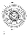
- FIG. 27 is a schematic top plan view of a filter cartridge including the component depicted in FIG. 27 ; in FIG. 27 , cross-lines showing a center and thus a location of a central cartridge axis.
- FIG. 28 is a schematic cross-sectional view of the component of FIG. 26 , taken generally along 28 - 28 , FIG. 6 .
- FIG. 29 is an enlarged fragmentary schematic view of an identified portion of FIG. 28 .
- FIG. 30 is a schematic top perspective view of the top piece component of FIG. 26 .
- FIG. 31 is a schematic side elevational view of a top cover component of the cover assembly depicted in FIG. 10 .
- FIG. 32 is a schematic top plan view of the component depicted in FIG. 35 .
- FIG. 33 is a schematic cross-sectional view of the component depicted in FIG. 35 , taken generally along line 33 - 33 , FIG. 32 .
- FIG. 34 is a schematic side elevational view of a mounting ring component of the cover assembly depicted in FIG. 10 .
- FIG. 35 is a top plan view of the mounting ring component depicted FIG. 38 .
- FIG. 36 is a schematic cross-sectional view of the ring component of FIGS. 34 and 35 , taken generally along line 36 - 36 , FIG. 35 .
- FIG. 37 is a schematic exploded perspective view of the cover assembly depicted in FIG. 10 .
- FIG. 38 is a schematic view of an engine and air induction system using a crankcase ventilation filter assembly in accord with the present disclosure.
- FIG. 39 is a schematic top perspective view of a second embodiment of a crankcase ventilation filter assembly according to the present disclosure.
- FIG. 40 is a schematic first side elevational view of the assembly depicted in FIG. 38 .
- FIG. 41 is a schematic top plan view of the assembly depicted in FIGS. 39 and 40 .
- FIG. 42 is a schematic cross-sectional view taken generally along line 42 - 42 , FIG. 40 .
- FIG. 43 is a schematic enlarged fragmentary view of an identified portion of FIG. 41 .
- FIG. 44 is a schematic cross-sectional view taken generally along line 44 - 44 , FIG. 41 ; the view of FIG. 44 generally being a right angle to the view of FIG. 42 .
- FIG. 45 is an enlarged, schematic, fragmentary view of an identified portion of FIG. 43 .
- FIG. 46 is a schematic top perspective view of the assembly of FIGS. 39 and 40 , with an access covered removed.
- FIG. 47 is a second schematic side elevational view of the assembly of FIGS. 39 and 40 .
- FIG. 48 is a third, schematic, side elevational view of the assembly depicted in FIGS. 39 and 40 .
- FIG. 49 is an enlarged, schematic, top perspective view of a filter cartridge component usable in the assembly of FIG. 39-48 .
- FIG. 50 is a schematic top plan view of the filter cartridge depicted in FIG. 49 .
- FIG. 51 is a first schematic side elevational view of the filter cartridge component depicted in FIG. 50 .
- FIG. 52 is a schematic cross-sectional view taken generally along line 52 - 52 , FIG. 51 .
- FIG. 53 is a second, schematic, side elevational view of the filter cartridge component of FIG. 49 ; the view of FIG. 53 being taken generally a right angle to the view of FIG. 51 .
- FIG. 54 is a schematic cross-sectional view taken generally along line 54 - 54 , FIG. 53 .
- FIG. 55 is a schematic exploded view of the assembly of FIG. 39 .
- FIG. 55 a is an enlarged, schematic, exploded view of a housing base component portion of FIG. 55 .
- FIG. 56 is a schematic top perspective view of a housing base component of the assembly of FIGS. 39 and 40 .
- FIG. 57 is a schematic top plan view of the housing base component of FIG. 55 .
- FIG. 58 is a second schematic top perspective view of the housing base component of FIG. 56 .
- FIG. 59 is a schematic bottom perspective view of a first, center, component of an access cover usable in the assembly of FIG. 39 .
- FIG. 60 is a schematic top perspective view of a second, perimeter ring, component of an access cover usable in the assembly of FIG. 39 .
- FIG. 61 is a schematic top perspective view of a support component of a filter cartridge usable in the filter cartridge of FIG. 49 .
- FIG. 62 is a schematic, enlarged, fragmentary cross-sectional view of a portion of the assembly of FIG. 39 .
- FIG. 63 is a schematic cross-sectional view taken generally along line 63 - 63 , FIG. 40 .
- FIG. 64 is a schematic, enlarged, fragmentary view of an identified portion of FIG. 63 .
- crankcase ventilation filter assemblies As indicated previously, the present disclosure relates, in general, to systems, arrangements, features, components and methods concerning crankcase ventilation filter assemblies.
- the Assignee of the present application is Donaldson Company, Inc. of Bloomington, Minn.
- the application in part, relates to other Donaldson Company, Inc. crankcase ventilation filter assemblies, including, for example, those described in WO 2007/053411; WO 2008/147585; WO 2008/115985; WO 2005/157251; and, WO 2009/018454; the complete disclosures of which each being incorporated herein by reference.
- crankcase ventilation filter assemblies that can provide advantage relating to one or more of: assembly operation; assembly servicing; component operation and/or servicing; and/or, assembly or component generation, as described herein.
- assembly operation relating to one or more of: assembly operation; assembly servicing; component operation and/or servicing; and/or, assembly or component generation, as described herein.
- assembly or component generation as described herein.
- a mounting location of limited vertical dimension may be characterized as a “vertically challenged” application situation.
- certain of the techniques described herein are particularly well adapted for “vertically challenged” installation situations.
- first embodiment in FIGS. 1-37 and a second embodiment in FIGS. 39-64 two embodiments are depicted, first embodiment in FIGS. 1-37 and a second embodiment in FIGS. 39-64 .
- identified features of the first embodiment can be incorporated in the second embodiment; and, identified features of the second embodiment can be incorporated in the first embodiment. This will be, in general, understood by a person of skill in the art based on the following descriptions of each embodiment.
- crankcase ventilation filter assembly General features and operation of an example crankcase ventilation filter assembly can be understood by reference to FIGS. 1-8 . Thus, attention is first directed to these figures.
- the reference numeral 1 generally depicts a crankcase ventilation filter assembly including example features according to the present disclosure.
- the assembly 1 can be generally characterized as comprising a housing 2 having: a gas flow inlet arrangement 3 ; a filtered gas flow outlet arrangement 4 ; and, a liquid drain outlet arrangement 5 .
- gas carrying liquid particulate therein is directed into the assembly 1 through gas flow inlet arrangement 3 .
- the gas flow is directed through a filter cartridge component 20 (not viewable in FIG. 1 ) discussed below.
- liquid component is coalesced and drained and other contaminant (such as solid particulate) tends to become trapped within media of the filter.
- the liquid component can drain downwardly, for example under gravity influence, to drain outlet arrangement 5 , and outwardly from housing 2 .
- the liquid draining out from the filter cartridge 20 and through the liquid drain outlet arrangement 5 can carry some of the solid particulate component from the media.
- the filtered gases leave the assembly 1 through filtered gas flow outlet arrangement 4 .
- the filtered gases can be vented to the atmosphere, or, in some instances, they can be directed other to componentry, such as to an engine air intake or induction system.
- the gas flow inlet arrangement 3 , the gas flow outlet arrangement 4 and the liquid drain arrangement 5 are each depicted as single apertures in single flow tubes. While this is typical, alternate assemblies are possible in which one or more of the gas flow inlet arrangement, gas flow outlet arrangement and/or liquid flow outlet arrangement is provided as a multiple aperture and/or multiple tube arrangement.
- the typical assembly 1 includes a housing 2 configured so that when installed on equipment for use, the liquid drain outlet 5 is directed downwardly.
- the liquid typically oil or a similar material that drains through outlet 5 , can be directed to a sump or back into equipment as desired.
- Valving arrangements can be used to manage liquid flow from the liquid drain outlet 5 to the equipment as desired.
- a first, optional, gas valve assembly is a regulator valve assembly, which, in the example depicted, regulates gas flow to the gas flow outlet arrangement 4 .
- a cover for the regulator valve assembly 10 is depicted in the example having a design thereon.
- the design is a source-indicating mark of Donaldson Company, Inc., the Assignee of the present application, for various equipment and services. It is noted that the design is typically used in association with the mark “Spiracle” another source indicating mark of Donaldson.
- Assembly 14 is depicted on optional pressure release valve assembly or vent valve assembly.
- Assembly 14 is generally configured to rapidly open and thus to allow venting of gases from an interior of housing 2 , to protect against an overpressure condition within housing 2 . Specific features of the vent valve assembly 14 are discussed further herein below.
- the example housing 2 depicted can be characterized as generally comprising two components: housing bottom or base component 16 ; and, service cover (cover assembly or component) 17 .
- the housing 2 is mounted on equipment with which the assembly 1 is to be used, for example a vehicle or other equipment.
- assembly 1 is mounted by having the housing base component 16 secured in place on the equipment.
- the particular housing 2 depicted is shown with mounting flanges 18 positioned on the housing base component 16 , to provide for this mounting, although alternate mounting approaches are possible.
- the service cover 17 is generally removably mounted on the housing base 16 , to allow service access to an interior of the housing 2 .
- Service access provides for installation and/or removal of an interiorly positioned filter cartridge arrangement 20 (not shown in FIG. 1 ) as discussed below.
- the particular housing 2 depicted is provided with a top, downwardly directed (inlet) gas flow tube arrangement 3 x as the gas flow (inlet) arrangement 3 .
- the inlet tube arrangement 3 x in the example depicted, comprises a portion of a cover component 91 of the access cover 17 , as discussed below, although alternatives are possible.
- the housing 2 is configured with gas the flow outlet arrangement 4 and the liquid drain outlet arrangement 5 positioned on the housing base 16 . Since the housing base 16 is generally the bottom of the assembly 1 , the drain outlet 5 will typically be positioned on this component. Positioning the gas flow outlet arrangement 4 on the housing base arrangement 16 is advantageous for the particular assembly depicted and gas flow therethrough, as will be understood from further discussion below.
- the housing base 16 comprises a single integral base member.
- the base 16 could comprise sidewall section and a removable bottom section, having similar overall features.
- the inlet arrangement 3 can be provided in the housing base with the outlet arrangement on the service cover, or both can be provided in the housing base or on the service cover. (Also, they can be directed differently). However especially for certain vertically challenged applications, the configuration depicted has some advantages, for reasons that will be apparent from descriptions herewith.
- the gas flow inlet direction, through inlet 3 , and the gas flow outlet direction through outlet 4 are generally perpendicular (orthogonal) to one another. This will be typical, although alternatives are possible.
- FIG. 2 a side elevational view of crankcase ventilation filter assembly 1 is provided, generally opposite the view of FIG. 1 .
- Mounting flanges 18 can be seen comprising a portion of mounting pad arrangement 18 x configured for mounting on a portion of equipment with which the assembly 1 is to be used.
- the mounting pad arrangement 18 x can be configured in a variety of specific arrangements. For example, it can be custom configured for engagement with a selected portion of equipment for use; the mounting pad arrangement 18 x depicted merely being an example.
- the housing base 16 can be provided without a mounting pad arrangement, with securement to the equipment alternately provided, for example through an attachable mounting band or similar structure.
- the assembly 1 will be mounted on the engine for the equipment of concern.
- the mounting pad arrangement 18 x can be configured for convenient mounting in this manner.
- the assembly 1 and in particular the housing 2 and an internally received cartridge 20 (not viewable in FIGS. 1-3 ), can be characterized as having a central assembly, housing, cartridge or component axis X.
- the axis X is depicted in FIGS. 1-3 , and is generally centrally located through each of the cover assembly 17 , base 16 , thus the overall housing 2 and an internally received filter cartridge 20 discussed below.
- the axis X is generally oriented vertically, in typical use.
- FIG. 3 a third side elevational view of the assembly 1 is depicted generally taken toward the left side of FIG. 1 .
- FIG. 4 a side view opposite that of FIG. 3 is provided.
- FIG. 5 is a top plan view of the assembly 1 .
- the example top cover or service cover 17 has an outer perimeter lip and that the inlet tube 3 x is centrally positioned relative to the outer perimeter 17 p of the service cover 17 .
- centrally positioned in this context, it is meant that the vertical inlet tube 3 x is positioned centered on a center (vertical) axis X ( FIGS. 1-4 ) defined where lines 7 - 7 and 8 - 8 cross at X, FIG. 5 .
- the access cover or service cover 17 has an outer perimeter 17 p .
- the “center” of the outer perimeter will generally be a location where a line along a longest dimension of that perimeter, across the service cover 17 , is intersected by a perpendicular line half-way along that longest line.
- the two lines could be a pair of orthogonal (perpendicular) diameter lines.
- the location where the two lines cross will be characterized as the “center” of the service cover 17 and perimeter 17 p . In a typical application, this center will also correspond to a central (vertical) axis X of the assembly 1 and a service cartridge 3 , as discussed below.
- the inlet tube 3 x is positioned “centrally” on the access cover 17 , it is thus meant that it is centered around the identified center above.
- the inlet tube 3 x is positioned “centrally” in the assembly 1 , it is meant that it is centered on the central cartridge axis X or housing central axis X as defined herein below.
- the inlet tube 3 x is centrally positioned with respect to each of: the outer perimeter 17 p of the service cover 17 , a cartridge central axis X, and a housing central axis X.
- inlet tube 3 x is not positioned centrally, i.e. when it is positioned “eccentrically.” In some arrangements, this can provide advantage, and features can be modified to accommodate for this, as discussed below.
- the particular tube 3 x depicted has an interior definition which is circular in cross-section. This will be typical, but is not specifically required all applications of the many of the principles described according to the present disclosure.
- the air flow inlet arrangement 3 i.e. the gas flow tube 3 x through the cover assembly 17 is eccentrically, axially, positioned on the central axis X, as opposed to being centrally positioned.
- the central positioning provides for some accommodation and advantage, discussed further below.
- FIG. 6 a bottom plan view of the assembly 1 is depicted.
- the housing base component 16 except for componentry positioned thereon, and some recesses at 16 j (discussed below) generally has a circular outer perimeter 16 p as well.
- the liquid outlet drain 5 is typically centrally positioned, as shown. It is noted that although alternatives are possible, typically, a central (not eccentric) position around center X will be typical and preferable for the drain outlet arrangement 5 , as will be understood from further discussion below. Still referring to FIG. 6 , it is noted that the particular liquid outlet arrangement 5 depicted comprises a tube 5 x having a generally circular interior definition, in cross-section. While this shape is not required, it will be typical.
- FIG. 7 a cross-sectional view taken generally along line 7 - 7 , FIG. 5 .
- the housing 2 can generally be understood to define a housing interior 2 i .
- serviceable filter cartridge 20 Within the housing 2 or housing interior 2 i is positioned serviceable filter cartridge 20 .
- Filter cartridge 20 generally comprises filter media 21 positioned surrounding an open filter interior 22 , positioned between, and typically extending between, opposite cartridge end pieces 23 , 24 and defining central cartridge axis X (in the example also corresponding to a central axis for housing 2 and assembly 1 ).
- the term “serviceable” when used in association with filter cartridge 20 is meant to refer to a filter cartridge 20 that can be removed and be replaced within the housing 2 .
- the filter cartridge 20 is a service component.
- the filter cartridge 20 will be removed and be replaced during servicing operation for the equipment involved, since the filter cartridge 20 will, in time, load with material.
- servicing in some instances can comprise refurbishment, but typically it will be replacement.
- the particular filter media 21 depicted is positioned around a central cartridge axis X.
- the axis X is generally a vertical axis extending through a center around which the media 21 is positioned, and also generally through a center defined by the housing base component 16 .
- inlet gas flow and liquid drain operation can be understood.
- gas enters through downwardly directed inlet tube 3 x it is directed into cartridge interior 22 .
- it is directed through the media 21 into filtered gas annulus 25 which, for the system depicted, is a portion of the housing interior 2 i that surrounds the cartridge 20 .
- Annulus 25 is a clean or filtered gas flow annulus in flow communication with outlet arrangement 4 , FIG. 1 .
- Liquid coalesced within the media 20 generally drains downwardly to housing bottom 2 b (which, for the housing 2 depicted, comprises bottom 16 b of base arrangement 16 ) and outwardly through drain arrangement 5 .
- the assembly 1 is configured for “in-to-out” flow through the filter cartridge 20 , during filtering.
- the gas flow through the media 21 , with filtering is, generally, from an inside 22 of the cartridge 20 to a region outside of the cartridge 20 .
- Many of the techniques described herein can be applied in applications in which an opposite “out-to-in” flow during filtering is involved. This is discussed briefly herein below.
- annulus 25 is in flow communication with port 35 ( FIG. 12 ) in a sidewall 16 s of base 16 .
- Port 35 (not viewable in FIG. 7 ) is configured with outlet 4 and the regulator valve assembly 10 thereon, as discussed further below.
- FIG. 8 a second cross-sectional view of assembly 1 , taken generally along line 8 - 8 , FIG. 5 , is depicted.
- cover 11 of regulator valve assembly 10 can be seen in position on port 35 .
- an aperture arrangement through end piece 23 in communication with open interior 22 .
- the aperture arrangement 30 in part, allows that should pressure build-up in the region of inlet 3 and interior 22 , to a potential over pressure condition, that pressure (via vent 30 ) is communicated to vent valve arrangement 14 , for release.
- Other paths for gas venting through end piece 23 are provided. This is discussed further below.
- an optional inertial impaction arrangement 31 at an internal end of inlet tube 3 x , to facilitate liquid collection.
- Advantages from such an optional inertial impaction arrangement 31 will be understood from further discussion below.
- gases are directed through inlet tube 3 x , they are directed toward inertial impaction plate 31 p , and a portion of liquid carried by the gases can collect on an upper surface 31 u of inertial impaction plate 31 p as droplets, which then can drop downward and flow into a liquid head to media 21 , without necessarily redispersing as aerosol, to advantage. Again, this is described in further detail below.
- FIGS. 39-64 does not depict the use of such an inertial impaction arrangement.
- an inertial impaction arrangement of the type depicted in FIG. 8 could be adapted for this latter embodiment).
- housing base component 16 a top perspective view of housing base component 16 is depicted. It is noted that the housing base component 16 is depicted in FIG. 9 , without selected portions of the regulator valve assembly 10 positioned thereon.
- the particular portion of housing base component 16 depicted generally will comprise a unit that can (if desired) be molded as a single, unitary, construction, from plastic. This will be typical for a preferred construction according to the present disclosure.
- the regulator valve assembly 10 is an optional component. If the housing base component 16 were part of an assembly which is does not include such a regulator valve assembly, or includes a regulator valve assembly alternately mounted, the housing base component 16 could be formed without those selected features of the regulator valve assembly 10 depicted, thereon.
- service cover or service cover assembly arrangement 17 is viewable in top perspective view.
- filter cartridge 20 is depicted in top perspective view.
- Assembly 1 can be assembled for use by installing cartridge 20 ( FIG. 11 ) in housing base component 16 ( FIG. 9 ) and positioning service cover 17 in place over a top end 16 e of housing base component 16 ( FIG. 9 ). (It is noted that typically housing base component 16 , FIG. 9 , will have been provided with remaining components of the regulator valve assembly 10 thereon before cartridge 20 and service cover assembly 17 are positioned.)
- the inlet arrangement 3 , outlet arrangement 4 and drain outlet arrangement 5 can be attached to appropriate conduits for gas flow and liquid flow as appropriate.
- there is no specific need to disattach (detach) hosing or tubing from the assembly 1 during serving, depending on the nature of the tubing attached. Indeed, typically the housing base component 16 remains in place and does not move; and, if the tubing attached to inlet arrangement 3 is sufficiently flexible, the access cover 17 , as will be understood from further discussion below, can be removed from the housing base 16 without disattaching the tubing from the inlet 3 .
- FIG. 12 is an exploded perspective view of housing base component 16 .
- selected componentry of the optional regulator valve assembly 10 is depicted and it is this componentry which is shown in exploded view.
- housing base component or base 16 is depicted in perspective view, as comprising sidewall 16 s , bottom 16 b with drain outlet arrangement 5 therein, open top end 16 e and mounting pad arrangement 18 x.
- FIG. 13 a side elevational view of base component 16 is provided, taken toward mounting pad arrangement 18 x . Also viewable in FIG. 13 , is lock projection arrangement 36 , on an outer surface of sidewall 16 s adjacent, and spaced from, top edge 16 e . Also, around an upper portion of sidewall 16 s , between lock projection arrangement 36 and open end 16 e is provided thread arrangement 16 t . As will be understood from discussion below, the particular assembly 1 depicted is configured so that service cover arrangement 17 is threadably mounted on housing base 16 at thread arrangement 16 t . Alternate methods of connection are possible, as shown in the embodiment of FIGS. 39-64 but a threaded connection is convenient here. (The non-threaded arrangement of FIGS. 39-64 can be adapted for the embodiment of FIG. 12 ). As will be understood from further discussion below, lock projection arrangement 36 is positioned to be engaged by a portion of service cover 17 in a manner inhibiting undesirable unlocking during use due to equipment vibration.
- Port 35 is mounted on, and typically molded integral with, sidewall 16 s .
- conduit ring 38 Positioned interiorly of port 35 is provided conduit ring 38 , also typically molded integrally with housing base 16 .
- An interior 38 i of ring 38 is in direct flow communication with interior 4 i of gas flow arrangement 4 . That is, for the example assembly 1 depicted, for gases to reach outlet 4 , they must flow into and through interior 38 i of ring 38 . Alternate constructions, however, are possible.
- a diaphragm valve member is depicted.
- a biasing arrangement is depicted, in the example depicted configured as a coiled spring 41 s .
- cover 11 When assembled, cover 11 is positioned over, and secures, diaphragm 40 over port 35 , closing the port 35 .
- Diaphragm 40 is supported spaced from end 38 e of inner ring 38 by biasing member 41 .
- the regulator valve arrangement 10 can be understood from the following example. Assume that the outlet flow arrangement 4 directs gas flow to an air cleaner or engine air intake. Fluctuation demands of the engine will fluctuate the amount of draw on the gas in outlet arrangement 4 . It may be undesirable to transfer such a negative pressure (or draw) into the assembly 1 and the cartridge 20 . Thus, the regulator valve 10 under the circumstance will tend to draw closed. More specifically, if the engine draw at outlet arrangement 4 is sufficient, this draw will tend to bias diaphragm 40 toward edge 38 e , inhibiting gas flow and inhibiting as high a vacuum condition from being transferred through housing 2 .
- the biasing arrangement 41 will bias the valve member 4 away from edge 38 e , opening gas flow.
- the biasing arrangement 41 and valve arrangement 40 can be configured so that if the draw at outlet tube 4 is sufficiently high, diaphragm 40 will completely close aperture 38 e . This is a matter of preference dependent up expected conditions and operation.
- a snap-fit can be used for the cover 11 , the snap-fit comprising apertures 11 a on the cover 11 engaging projections 35 p on the port 35 . This will secure the diaphragm 40 and the biasing arrangement 41 in place.
- Regulator valve arrangements have been used in connection with crankcase ventilation filter assemblies before, and examples are depicted in WO 2007/053411; WO 2008/147585; WO 2008/115985; and, WO 2009/018454, incorporated herein by reference.
- FIG. 13 again, a side elevational view of housing base 16 is depicted. The view is taken generally toward mounting pad 18 x .
- Selected previously identified features viewable include: Sidewall 16 s , top end 16 e with threads 16 t adjacent thereto; lock arrangement 36 , mounting pad 18 x with flanges 18 ; and bottom 16 b with outlet 5 (as tube 5 x ).
- Central housing axis X which also corresponds to a central cartridge axis is depicted, directed through bottom drain outlet 5 , and for the example depicted the drain outlet 5 is centered on axis X.
- Outlet arrangement 4 previously discussed, is also depicted.
- FIG. 14 a top plan view of housing base component 16 is depicted.
- the view in FIG. 14 is generally of the housing base component 16 , without mounting of the separable components of the regulator valve assembly 10 thereon.
- the view in FIG. 14 is of the base 16 as it can be molded as a single integral piece.
- selected exterior features of the housing base component 16 include: Port 35 ; outlet 4 ; lock arrangement 36 ; mounting pad 18 x with flanges 18 and sidewall 16 s.
- FIG. 14 it can be seen that the particular housing base component 16 depicted, includes only one lock projection 36 x as lock projection arrangement 36 , FIG. 12 . It is noted that in some applications of the techniques described herein, the lock projection arrangement 36 can include two or more lock projections 36 x.
- housing base component 16 generally includes sidewall 16 s defining a generally circular interior 16 i .
- the circular interior 16 i extends around, and is typically concentrically positioned relative to central axis X, FIG. 13 , which a vertical axis extending through the housing 2 and the cartridge 20 .
- Alternatives are possible.
- FIG. 14 an interior surface 16 z of bottom 16 b can be seen.
- the interior surface 16 z of bottom 16 b includes a plurality of radial ribs 41 thereon, which, in part, provide strength to the bottom surface 16 z.
- FIG. 14 at 5 o , an opening to the bottom drain arrangement 5 , FIG. 1 , is shown.
- a projection arrangement 44 Positioned adjacent opening 5 o for the drain 5 , FIG. 14 , is a projection arrangement 44 .
- the projection arrangement 44 generally projects from a portion of bottom surface 16 z in a direction away from drain 5 and generally toward upper end 16 e of base 16 ; i.e. toward service cover 17 , FIG. 1 .
- Projection arrangement 44 is configured to interact with serviceable filter cartridge 20 in manners discussed below.
- the projection arrangement 44 is a member of a (first) projection/receiver arrangement, of which another member is positioned on the cartridge 20 .
- projection arrangement 44 is (optionally) also part of a cartridge-to-housing component (or housing component-to-cartridge) rotational orientation (or alignment) indexing arrangement, which ensures that the cartridge 20 is installed in a selected rotational orientation relative to the housing base component 16 . This helps ensure that the cartridge 20 is a proper cartridge for the assembly and is appropriately oriented.
- tabs 16 k are radially inwardly projecting tabs 16 k , formed by recesses 16 j , FIG. 12 .
- the tabs 16 k are oriented adjacent bottom 16 z , and will mate with selected portions of a cartridge 20 as discussed below.
- FIG. 15 a cross-sectional view taken generally along line 15 - 15 , FIG. 14 .
- the projection arrangement 44 can be seen projecting toward end 16 e and, in assembly 1 , FIG. 1 , toward access cover 17 .
- FIG. 14 that in FIG. 15 , half of the projection arrangement 44 is depicted, the opposite half typically being a mirror image.
- features of projection arrangement 44 configured for interaction with the cartridge 20 will be better understood from discussion below after the cartridge 20 is discussed.
- FIG. 15 other features viewable in the cross-section, as previously described, include: threads 16 t ; port 35 ; inner ring 38 ; mounting pad 18 x ; bottom ribs 41 , projection 16 k ; and, drain outlet 5 o . It can be seen that the ribs 41 create flow spaces therebetween for drain flow under a received cartridge 20 , in use.
- FIG. 16 is a fragmentary cross-sectional view of a portion of FIG. 15 .
- Rib 35 r is shown positioned in port 35 to engage a rim portion of the diaphragm 40 , FIG. 12 , to facilitate sealing.
- FIGS. 11 and 17-30 The Filter Cartridge Generally, FIGS. 11 and 17-30
- the filter cartridge 20 generally comprises media 21 positioned in extension around an open filter interior 22 .
- the media 21 is positioned between opposite first and second end pieces 23 , 24 .
- the media 21 is generally configured to receive gases directed therethrough, and to allow for coalescing of liquid within the media 21 with trapping of certain contaminant.
- a variety of media appropriate for gas/liquid separation can be used, and the choice of one for the application of interest is not critical to many of the particular features described herein.
- Example usable media include those described in WO 2006/084282; WO 2007/0535411; WO 2008/115985; and, WO 2006/91594 incorporated herein by reference.
- the particular cartridge 20 depicted is configured to be vertically oriented when installed. That orientation is typically with first end piece 23 oriented as an upper end piece and with second end piece 24 generally oriented as lower or bottom end piece.
- first (upper) end piece 23 includes an outer perimeter region 23 p , which, in the example depicted, comprises a housing seal member 50 .
- housing seal and variants thereof as used herein, is meant to refer to a seal member positioned on a serviceable cartridge 20 such that when the cartridge 20 is installed in a housing 2 , the housing seal member 50 is positioned and configured to form a seal with a portion of a housing 16 .
- a “housing seal” as the term is used herein, is a seal that is releasable, i.e. which separates from sealing when the cartridge 20 is removed from the housing 2 , without damage to the housing 2 or seal member 50 .
- housing base 16 includes, in sidewall 16 s , an upper seal shoulder 16 x spaced downwardly from end 16 e .
- the shoulder 16 x receives pushed downwardly (axially) thereagainst, lower end 50 e of seal member 50 , when the cartridge is installed. Sealing occurs by the downward (axially directed) force on the seal 50 against the shoulder 16 x .
- the shoulder 16 x includes a rib 16 h thereon, FIG. 15 that will be pressed into the seal member 50 .
- Such a seal is sometimes referred to as axially directed seal, since the sealing forces are in the longitudinal direction of extension of central axis X.
- Such seals are sometimes referenced as “pinch” seals, since the sealing occurs by pinching the seal member 50 between housing components.
- the seal member 50 can be seen as pressed downwardly against shoulder 16 x to cause the sealing described.
- Ribs 16 h is viewable.
- viewable is a portion 17 z of access cover 17 oriented to push downwardly on seal member 50 , as the cover 17 is mounted, to facilitate sealing.
- a radially directed seal is configured with sealing forces, directed generally toward or away from central axis X).
- shoulder 16 x is surrounded by upwardly directing flange 16 r .
- Flange 16 r has a threaded outer surface.
- the inside portion of flange 16 r is provided with optional recesses or grooves 16 f therein, extending generally aligned with axis X. It is not intended that the surface 16 r be used as a seal surface in the assembled filter arrangement. Grooves 16 f will help inhibit any such use.
- ribs can be included on surface 16 r to, in part, address this issue also. (If surface 16 r was intended to be used as a seal surface for a radial seal, the ribs 16 f would not be present).
- upper end piece 23 is depicted as having gas flow aperture 51 extending therethrough, in communication with the open filter interior 22 .
- Aperture 51 for an in-to-out flow system as depicted, is an aperture that allows for gas flow entry, of gas to be filtered into interior 22 .
- the upper aperture 51 receives, projecting therethrough, a portion of inlet tube 3 x , as discussed further below.
- the aperture 51 is sized and configured to have a largest dimension thereacross of at least 8 mm, usually at least 10 mm and often an mount within the range of 15-40 mm, usually 15-25 mm, although alternatives are possible.
- the particular aperture 51 is circular in outer perimeter definition, although alternatives are possible.
- the first end piece 23 is a multi-piece construction, comprising: a preformed, typically rigid, central frame portion 23 x ; and, seal member 50 comprising a gasket secured to, or molded-in-place on, the frame portion 23 x .
- the rigid portion 23 x has an upper surface 23 u with strengthening ribs 23 r thereon, in the depicted example.
- the particular cartridge 20 depicted includes a projection arrangement 55 projecting upwardly from central frame portion 23 x , of end piece 23 , in a direction generally away from end piece 24 of media 21 .
- the projection arrangement 55 comprises at least one projection 55 a , in the example at least two projections 55 a , each of which project away from the media 21 a distance of (at least) 5 mm, usually at least 10 mm, and often at least 15 mm in total height, from adjacent portion of ridge center 23 x .
- the projection arrangement 55 can be used to facilitate radial orientation of the access cover 17 relative to the cartridge 20 and a housing base 16 , as discussed below. (It is noted that the cartridge 20 can be configured with only a single such projection, for example, in accord with the embodiment of FIGS. 39-64 ).
- the projection arrangement 55 also comprises a handle arrangement 56 .
- the handle arrangement 56 facilities grasping of the cartridge 20 for installing it in the housing base component 16 and removing it therefrom.
- the particular handle arrangement 56 depicted comprises at least one, and in the example two, handle member(s) 56 b (although a single handle member could be used).
- the two handle members 56 b are radially spaced, arcuate, extensions 56 b , each projecting upwardly and laterally outwardly, and thus having an axial extension 56 a and an upper, radial (outward) lip or rim 56 s .
- the lips or rims 56 s are oriented and shaped to facilitate handling of cartridge 20 .
- the two projection members 55 a each have an arcuate shape around a central axis X, FIG. 8 that extends around an axis X over an angular arc of at least 50°, usually an amount within the range of 50°-150°, inclusive, and often at least 70°, although alternatives are possible. Further, the two projection members 55 a are closer to one another at one end than in another. Alternately stated, the projection members 55 a , in the example depicted comprising handle member 56 b , are asymmetrically positioned around central axis X.
- each member 56 need not necessarily extend in a plane perpendicular to axis X. That is, upper edges 56 a can slant upwardly in extension from one end of each member 55 a to the other.
- FIG. 17 a top plan view of the cartridge 20 ; the view of FIG. 17 , therefore being taken toward upper surface 23 u of end piece 23 . It can be seen that the depicted aperture 51 is centrally positioned, i.e. is centered on a central axis X of the cartridge 20 and media 21 , FIGS. 7 and 8 .
- FIG. 18 a cross-sectional view taken generally along line 18 - 18 , FIG. 17 .
- features previously described and viewable generally include: media 21 surrounding and defining open filter interior 22 , and in the example depicted, centered on central axis X; end piece 23 with central aperture 51 therethrough, outer perimeter 23 p with housing seal member 50 to provide seal end 50 e ; and, second end piece 24 . Further, portions of the handle members 56 b (projections 55 a ) are viewable.
- recess 56 r under lips 56 s , of the handle members 56 b can be seen. It will be understood that this will facilitate grasping the cartridge.
- lip 56 s will be configured so that the space underneath it has a vertical dimension of at least 5 mm, typically at least 7 mm. Again, this space or recess 56 r can increase if upper lips 56 s slant upwardly.
- perimeter 23 p and seal member 50 are positioned surrounding an end (in the example upper end 21 u ) of media 21 .
- the seal member 50 and perimeter 23 p extend axially toward end piece 24 , from upper end 21 u of the media 21 , an amount of at least 3 mm, typically at least 5 mm and often at least 7 mm, for example, within the range of 7-20 mm.
- a distance as described has advantages for “vertically challenged” applications, as discussed below.
- the first end piece 23 includes a perimeter rim 23 p having a portion projecting at least 3 mm toward the second end piece 24 while also completely surrounding the media 21 .
- This portion typically projects at least 5 mm, usually at least 7 mm and typically an amount within the range of 7-20 mm as defined.
- an axial extension of the rim portion 23 p which both extends in the axial direction of the second end piece 24 and which also surrounds, completely, the media pack 21 has the minimum distance or distance range as defined. Portions of the preform 23 which do not surround the media 21 are not counted within this dimensional definition. Reasons for this will be understood from certain discussions below.
- the feature of the perimeter 23 p and seal member 50 having at least a portion thereof surrounding the media 21 distinguishes the specific units depicted in WO 2008/115985; WO 2008/157251; and, WO 2009/018454, incorporated herein by reference. It is noted that with the arrangements depicted in WO 2008/115985; WO 2008/157251; and, WO 2009/018454, it was described that the cartridge could comprise a spool shaped, integral, preform member, with the upper end piece and lower end piece formed integrally with a central cartridge support. This was readily possible, because the media could be wound in place on the central cartridge support or spool.
- the preferred cartridge 20 depicted comprises multiple components that are secured together, for example with a snap fit or other attachment arrangement, to form the full rigid framework portion thereof after the media is in place. These components can be viewed in FIG. 18 , as comprising: upper end piece 23 ; and, central cartridge support 61 .
- the central cartridge support 61 and bottom end piece 24 can (optionally) be formed as a single integral unit, for example, molded from plastic, and the end piece 23 can be secured thereon, for example with a snap-fit or other attachment arrangement, after the media 21 is in place.
- first end piece 23 , second end piece 24 , and central cartridge support 61 can be separately made and be secured together. Further, in some applications, the first end piece 23 can be secured integral with the central cartridge support 61 , and the second end piece 24 can be snap-fit in place.
- first end piece includes a perimeter 23 p that projects axially as described, it will be convenient to load the media 21 onto the central cartridge support 61 before the end piece 23 is in place. Since there is no similar rim which would interfere with assembly on the second end piece 24 , it is convenient to form the central cartridge support 61 and second end piece 24 integral with one another, as a preform 60 .
- FIG. 19 an exploded perspective view of the cartridge 20 .
- viewable are: the first or upper end piece 23 comprising preform center section 23 x with aperture 51 therethrough, and seal member 50 , shown as exploded from one another.
- the seal member 50 is positioned on (molded-in-place on) piece 23 and is not removable therefrom, although alternatives are possible.
- perimeter apertures 23 o are positioned in a perimeter of piece 23 x .
- preform 60 comprising central cartridge support 61 and end piece 24 .
- media or media pack 21 is viewable.
- the media 21 is schematically depicted and can comprise a variety of arrangements including: a cylindrical construction formed as a unit or as a coiled construction of media, or alternate configurations.
- FIG. 19 is not meant to indicate that the cartridge 20 would be assembled by fitting the parts together in the matter shown, rather the exploded view is provided to understand the various components. Typical assembly will be discussed further herein below.
- FIG. 20 an alternate exploded view is depicted, generally analogous to FIG. 19 , except showing that the end piece 23 would be typically be pre-assembled with seal arrangement 50 thereon.
- preform 60 would be prepared and the media 21 would be positioned thereon.
- the media 21 for example, can comprise media coiled around central cartridge support 61 .
- the central cartridge support 61 includes a member 65 of a cartridge engagement arrangement 66 , for engagement with another member 67 on end piece 23 .
- the cartridge engagement arrangement 66 is a snap-fit projection/receiver arrangement, configured so that when the two members 65 , 67 are brought together, they engage in a snap-fit manner inhibiting separation.
- first member 67 is a receiver arrangement
- second member 65 is a projection arrangement; in the example depicted the projection arrangement 65 comprising a hook arrangement and the receiver arrangement 67 comprising a receiver aperture arrangement.
- the projection arrangement 65 comprises a plurality of flexible snap-fit hooks 65 a ; and, the receiver arrangement 67 comprises a plurality of receiver apertures 67 o ; the hooks 65 a and the apertures 67 o being positioned and configured so that when the end piece 23 is pushed over upper end 61 u of preform 60 , the hooks 65 a are deflected radially inwardly until they pass through selected ones of the apertures 67 o , at which point they snap back with the hooks 65 a preventing the end piece 23 from separating from the cartridge support 61 .
- the media 21 can be coiled onto the support 61 , even though the upper end piece 23 supports a seal arrangement that surrounds a location projecting along a side of the media.
- vertical space is saved (or more effectively used) by not requiring the seal arrangement 50 to be above the media 21 and thus to engage a housing surface at this location.
- the receiver arrangement 67 comprises a plurality of receiver apertures 67 o spaced from central aperture 51 , but generally positioned oriented around central axis X.
- the apertures 67 o are in communication with the open filter interior 22 .
- end piece 24 is viewable, along with selected features thereof.
- end member 24 includes a central receiver or aperture 24 o therein, which defines a closed external receiver 24 u for projection arrangement 44 , FIGS. 7 and 8 , on the housing base 16 during cartridge installation.
- Aperture 24 o extends through a lower most portion 24 x of member 24 , but it forms a closed external receiver 24 u by comprising an arrangement projecting upwardly from portion 24 x in preform 60 , FIG. 20 .
- This closed external receiver arrangement 24 u FIG. 21 is discussed further below.
- aperture 24 o can be viewed as a depression in bottom 24 x as opposed to an open aperture through the material of the preform 60 .
- end piece 24 includes a media axial overlap drain arrangement in accord with various ones of the features described in WO 2007/053411; WO 2005/115985; WO 2008/157251; and, WO 2009/018454, incorporated herein by reference.
- the media axial overlap drain arrangement is generally a portion of a lower end piece 24 , in this instance portion 24 r , which is a direct axial overlap with the media 21 , so that liquid collected within the media 21 can at least, in part, drain directly downwardly through the end piece 24 , without needing to pass completely through the media pack 21 along with the filtration gases.
- the media axial overlap drain arrangement comprises a plurality of recesses 70 r in an outer perimeter 70 of the end piece 24 .
- the recesses 70 r recess toward central aperture 24 o (or central axis X) from outer perimeter 70 , the locations axially overlapped by the media 21 ; i.e. to locations positioned directly underneath the media 21 when the cartridge 20 is oriented for use.
- gas flow during filtration is from a media inner perimeter 21 i , FIG. 18 , to an outer perimeter 21 p , FIG. 18 .
- liquid will coalesce within the media 21 and begin to build-up a liquid head therein.
- Some of this liquid can drain efficiently downwardly through the recesses 70 r , FIG. 21 , i.e. through the bottom end 21 b of the media 21 , without needing to pass all the way to the outer perimeter 21 p .
- some of the liquid may be pushed all the way to the outer perimeter 21 p by the gas flow.
- the axial drain arrangement underneath the media 21 helps efficient flow of the coalesced liquid from the media 21 and facilitate operation. Again, such features are similar to ones described in various publications referenced above. It is noted that additional apertures can optionally be included through end member 24 to facilitate liquid drainage.
- projections 16 k in a bottom portion of housing base 16 are sized and positioned to project into selected ones of recesses 70 r ( FIGS. 11, 20 and 21 ) of lower end piece 24 of cartridge 20 .
- This helps ensure that as the cartridge 20 is lowered into the housing base 16 , the cartridge 20 and housing base 16 are rotationally oriented appropriately relative to one another and that the cartridge 20 is a proper one for use in the assembly 1 .
- the projections 16 k are optional, but, again, do help the service provider understand that the cartridge 20 is an appropriate one for the system in which it is being inserted.
- receivers 70 r and projection 16 k also helps maintain a cartridge in appropriate orientation during handling and use. It is noted that not all of the receivers 70 r would be expected to have projection 16 k extending therein, rather, typically, a majority of the receivers 70 r would not.
- FIG. 22 a side elevational view of the preform 60 is provided.
- Features previously described include: end piece 24 ; central cartridge support 61 ; and, member 65 of the engagement arrangement 66 , comprising hooks 65 a.
- FIG. 23 a top plan view of preform 60 is shown. It can be seen, referring to FIG. 23 , that individual hooks 65 a do not all have the same perimeter dimension, rather some are narrower and at least one is wider; for example at 65 z , a wide hook is depicted and at 65 y a narrow hook is depicted.
- various ones of apertures 73 which operate as receivers for the second member 67 of the engagement arrangement 66 are narrow or wide, at 73 x a wide aperture being shown and at 73 y a narrow are being depicted.
- narrow and wide hooks 65 a and receiver apertures 73 are selected so that the end piece 23 can only be snap-fit on the preform 60 in one (or a limited number) of relative rotational orientations, preferably only one relative rotational orientation. Alternatives are possible.
- the central cartridge support 61 comprises an open porous structure, and in the example depicted, comprising a plurality of supports 75 interconnected by ribs 76 . From the above description of operation of the assembly 1 , it will be understood that gas generally flows through the open pores 77 formed in central cartridge support 61 from this construction.
- the receiver 24 u optionally defines a single receiver (projection) member 78 positioned offset from central axis X.
- the receiver (projection) member 78 is configured to receive projecting upwardly therein, a portion of projection arrangement 44 in housing base 16 . The manner in which this optionally provides for selected rotational orientation of the cartridge 20 relative to the housing base 16 is discussed further below.
- FIG. 23 again, a top plan view of central cartridge support 70 is provided. Wide hook 65 z and narrow hooks 65 y can be seen. It is noted that the particular preform 60 depicted, includes only one wide hook 65 z although the principles can be practiced with alternate constructions. Also viewable in FIG. 23 are features previously discussed as follows: recesses 70 r in end piece 24 ; and, receiver 24 u comprising projection member 78 .
- FIG. 24 a cross-sectional view taken generally along line 24 - 24 , FIG. 22 is depicted.
- features previously discussed and viewable include: central cartridge support 61 with ports 77 therein; hooks 65 a ; end piece 24 with a perimeter rim 70 ; and, central receiver 24 u defined by receiving member 78 .
- FIG. 25 an enlarged fragmentary cross-sectional view taken generally along line 25 - 25 , FIG. 22 is provided. This is a downward view into a lower portion of the receiver 24 u along an inside thereof.
- FIGS. 26-30 selected features of the top piece 23 can be viewed.
- a top perspective view of the end piece 23 is shown. Viewable within the figure are previously described features as follows: central portion 23 x with upper surface 23 u and ribs 23 r ; perimeter 23 p with housing seal member 50 ; central aperture 51 , centrally positioned; projection members 55 a ; and, apertures 73 which, as described above, operate as a receiver arrangement 67 for the projection arrangement 65 comprising hook 65 a , previously described.
- a single wide aperture 73 x for receipt of the single wide hook is shown. This ensures, again, that the top piece 23 can only be snap-fit on the preform 60 in a single rotational orientation, although alternatives are possible.
- FIG. 27 a top plan view of the cartridge 20 is provided and viewable are features previously described such as: central aperture 51 ; apertures 73 including wide aperture 73 x ; and perimeter 23 p including seal 50 thereon.
- FIG. 28 a cross-sectional view taken generally along line 28 - 28 , FIG. 26 , is provided. Viewable features previously discussed in perimeter 23 p with seal 50 ; central aperture 51 and portions of projection members 55 a.
- FIG. 29 an enlarged fragmentary cross-sectional view of an identified portion of FIG. 28 is indicated.
- Viewable is a rib 80 projecting downwardly from a center portion 23 x of the piece 23 , (on an inner or inner surface 23 i ) spaced radially inwardly from perimeter 23 p .
- cover 23 has a plurality of (in the example three) ribs 80 .
- the ribs 80 will generally press into the media 21 , when the piece 23 is snap-fit in place on the preform 60 with the media 21 in place.
- the ribs 80 will inhibit a gas flow path across the end piece 23 above the media 21 .
- the ribs 80 will be adequate to inhibit gas flow bypassing the media 21 , to the extent typically desired for a crankcase ventilation filter operation.
- the ribs 80 are concentric, and central with respect to central axis for the cartridge 20 . While this is typical, alternatives are possible. (It is noted that such ribs, or rib arrangements, can be implemented in the embodiment of FIGS. 39-64 , if desired).
- end piece 23 includes a rib arrangement thereon, along an inner or lower surface thereof.
- the rib arrangement can comprise one or more ribs 80 typically continuous in extension around central axis X, typically concentric therewith and concentric with each other.
- the rib arrangement comprises one or more ribs 80 configured to push into media, when the end piece 23 is installed in the cartridge 20 , to advantage.
- the particular end piece 23 depicted includes three ribs 80 radially spaced from one another, and each concentric with a central axis of the cartridge. Alternatives are possible.
- FIG. 30 a perspective view of end piece 23 is viewable. Features previously described are shown.
- the assembly 1 depicted includes arrangements helping to ensure that: the cartridge 20 is a proper one for the assembly 1 of concern, is properly oriented in the housing 2 when installed, and is secured in a proper orientation as the assembly 1 is used.
- features that relate to engagement between the filter cartridge 20 and the housing base component 16 , that facilitate this, are described, along with the general interaction between the cartridge 20 and the base component 16 that result.
- features for preferred interaction between the cartridge 20 and service cover 17 are also provided.
- FIGS. 14 and 15 Attention is again directed to FIGS. 14 and 15 with respect to the projection arrangement 44 in housing base component 16 .
- a top plan view of the projection arrangement 44 is depicted.
- the view of FIG. 14 is generally a view of the inside 16 z of bottom 16 b of the housing base component 16 .
- the projection arrangement 44 is shown positioned adjacent and spaced from, central drain aperture 5 o leading to drain 5 .
- the projection arrangement 44 comprises a projection member 85 .
- the off-set from drain aperture 50 allows drainage of liquid and bottom surface 16 z to aperture 50 .
- Interior 16 z of surface 16 b can be somewhat funnel shaped, to facilitate the draining.
- the receiver 24 u ( FIG. 21 ) in the bottom end piece 24 is positioned to project upwardly to define a projection or receiver pocket 78 .
- the receiver pocket 78 is sized, shaped and oriented to receive the projection member 85 projecting therein, as the cartridge 20 is lowered into housing base component 16 .
- the assembly 1 includes a projection/receiver arrangement comprising a projection 44 in the housing base, and a receiver 24 u in the cartridge, which engages one another when the cartridge is inserted.
- the projection (defining the receiver pocket) 78 comprises a structure that extends toward a top 78 t , FIG. 20 , at least 5 mm into cartridge open interior 22 , from the lower end 21 b of the media 21 , typically at least 10 mm, usually at least 15 mm, and often an amount within the range of 15-50 mm.
- the projection 44 in the housing base 16 also typically includes at least this amount of extension.
- the projection/receiver also be oriented to provide rotational orientation of the cartridge 20 relative to the housing base 16 .
- the particular projection/receiver arrangement depicted provides for this advantage, as follows.
- the example assembly depicted then is configured, so that the cartridge 20 can only be oriented in a specifically identified rotational orientation relative to the housing 16 , during installation.
- This rotational orientation for the example depicted corresponds to rotational alignment when the projection arrangement 44 (fin 85 ) is properly aligned with respect to the receiver 24 u (projection 78 ), so that the cartridge 20 can be fully lowered. This is, in part, due to optional eccentric positioning of receiver 24 u (or projection 78 ) relative to central axis X.
- projection/receiver arrangements can be used to accomplish the intended result, and the specific configuration of the receiver 24 u (projection 78 ) and projection arrangement 44 are merely examples. Further, the arrangement can be configured for a different number of specific orientations are possible, if desired.
- the projection/receiver arrangement comprising the projection arrangement 44 and receiver 24 u operates to help ensure that the cartridge 20 is the proper one of the assembly 1 involved; and, to help ensure that the cartridge 20 is securely retained and does not shift in orientation, as the equipment on which the assembly 1 is used vibrate or subjected to shock.
- engagement between the projection 16 k and the recess 70 r at the lower end piece 24 also facilitate rotational orientation of the cartridge, FIG. 20 .
- initial engagement for rotational alignment will be as the receiver 24 u (projection 78 ) begins to receive the projection 44 .
- a service cover (access cover) or cover assembly 17 was identified, which is secured in place on housing base component 16 in use, to close the housing 2 .
- a top perspective view of the access cover 17 is provided.
- the access cover 17 for the arrangement depicted comprises: outer perimeter mounting ring 90 , central cover section 91 ; and, optional evacuation valve or vent valve arrangement 14 .
- the mounting ring 90 is rotatable relative to the cover section 91 , so that the mounting ring 90 can be rotated for securing the cover assembly 17 onto the housing base 16 , without rotating cover section 91 . Advantages from this will be apparent from further discussion below.
- FIG. 34 a side elevation view of perimeter mounting ring 90 is provided.
- FIG. 35 top plan view of the perimeter mounting ring 90 is provided, and in FIG. 36 , a cross-sectional view taken generally along line 36 - 36 , FIG. 35 is provided.
- the mounting ring 90 is generally configured with a central aperture 92 therethrough, allowing the ring 90 to be positioned over, and slidably surrounding, ring 91 , FIG. 10 .
- An outer perimeter 93 of the perimeter ring 90 is provided with spaced grips 94 to facilitate gripping and rotating.
- the depicted mounting ring 90 includes downwardly projecting uneven or toothed ring section 95 , comprising individual downwardly projecting teeth 96 . Gaps 97 between the teeth 96 facilitate locking engagement with a portion of the housing 2 , to inhibit unlocking of the ring, once tightened, by vibration of the equipment on which the assembly 1 is used. This is discussed further below.
- FIG. 36 it can be seen that interior surface 91 i of ring 91 is threaded, for engagement with threads 16 t on housing base component 16 , discussed previously. It is noted that an alternate rotational connection approach, not involving threads, for example involving a projection/receiver connection analogous to the embodiment of FIGS. 39-64 can be used here.
- FIG. 2 Attention is now directed to the side elevational view of FIG. 2 and the cross-sectional view of FIGS. 7 and 8 .
- ring 90 is tightened on housing bead 16 (in the example on threads 16 t ) FIG. 2 , sufficiently so that ring 90 is lowered until one of the gaps 97 engages upward projection 36 on locking projection arrangement 36 .
- equipment vibration alone will not likely cause ring 91 to loosen on housing 16 .
- sufficient force (provided by a person rotating ring 90 ) to overcome the rotational interlock between projection 36 x and adjacent teeth 96 will be needed.
- FIG. 37 Attention is now directed to FIG. 37 , in which the cover or cover assembly 17 is depicted in exploded view.
- mounting ring 90 is viewable, as well as cover section 91 .
- the cover section 91 is configured with an outer perimeter 91 p having an outwardly directed perimeter ring 100 projecting radially outwardly therefrom.
- ring 90 is positioned over the top of cover 91 , such that inwardly directed lip 90 s on ring 90 rests on and above radial lip 100 of cover section 91 .
- Cover section 91 FIG. 37
- Cover section 91 can be provided with a radial interference portion as shown at 101 , so that once ring 90 is pressed over cover 91 , it tends not to separate by upper movement, unless forced. A small amount of interference can be used to affect this.
- vent valve assembly 14 Referring again to FIG. 37 , attention is directed to vent valve assembly 14 .
- Vent valve assembly 14 FIG. 37 is shown in exploded view over vent valve aperture 105 through cover 91 .
- a cross-sectional view of the vent valve assembly 14 is viewable in FIG. 8 .
- vent valve assembly 14 comprises valve member 107 seated, when the valve arrangement 14 is closed, access aperture 105 .
- the valve member 107 is positioned on and supported by support disc 108 .
- the support disc 108 is biased to maintain the valve member 107 in the closed position, (until overcome by internal pressure within assembly 1 ) by biasing arrangement 109 , in the example depicted comprising spring 109 s .
- Cover 110 is positioned over the valve assembly, the cover 110 having an outer perimeter 112 , FIG. 37 , with vent flow gaps 113 therein.
- the cover 110 is secured in place by a snap-fit over projections 114 .
- the central cover section 91 is depicted.
- the cover section 91 can be viewed as comprising flow arrangement 3 comprising tube 3 x ; outer perimeter 91 p with perimeter lip 100 thereon; and, interference projection 101 .
- a portion 3 w of tube 3 x projecting underneath cover 91 , with inertial impaction arrangement 31 thereon, comprising shelf 31 u supported by spaced projections 31 p , defining lateral gas flow exits 31 x therebetween. It can be seen that as gas enters tube 3 x , it will project downwardly toward inertial impaction arrangement 31 and surface 31 u , liquid may collect on surface 31 u , to drop downwardly, when the assembly 1 .
- receivers are positioned in centerpiece 91 .
- Receivers 120 are open underneath and are sized to receive projecting therein, projection members 55 a on the cartridge 20 .
- the size and shape of the projection members 55 a is configured to mate with the receivers 120 in only one rotational orientation (or in one of a selected identified specific, spaced, rotational orientation) of the cartridge 20 and access cover 17 (i.e. cover 91 , around central axis X). This facilitates a rotational indexing.
- receivers 120 are depicted with a slant or downward taper thereto.
- the handle arrangement can be configured analogously if desired.
- tube 3 w is depicted in the example indicated beneath inertial impaction arrangement 31 .
- lower end 3 z of tube 3 extends downwardly into housing base 16 , when cover assembly 17 is installed, to a location lower than an uppermost top 78 t of projection 78 in the cartridge 20 .
- the extension is to a location at least 3 mm lower than top 78 t , and usually at least 5 mm.
- the extension will typically be to a location at least within the range of 5-50 mm below top 78 t , although alternatives are possible. This level of extension can be understood for example, by reference to the cross-sectional view of FIGS. 7 and 8 .
- end 125 includes a perimeter 125 p with a recess 125 r therein, sized to fit around a portion projection 78 in an interior of the cartridge 20 , as the service cover 17 is lowered.
- the receiver 125 r and the particular example shown is sized so that the access cover 17 , and in particular portion 91 , must be rotationally aligned so that the receiver 125 r can receive the projection 78 projecting therethrough.
- receiver 125 r and end 125 are configured such that only one rotational orientation relative to projection 78 is possible.
- FIG. 32 a top plan view of cover section 91 is viewable.
- FIG. 33 a cross-sectional view taken generally along line 33 - 33 , FIG. 32 is viewable.
- projection arrangement 44 in the housing base 10 and the receiver 78 in the cartridge 20 comprise a projection/receiver arrangement with respect to the cartridge 20 housing base 16 .
- This arrangement also helps secure the cartridge against movement, once installed.
- This projection/receiver arrangement can, optionally, serve as a rotational (alignment) indexing arrangement by which it can be ensured that the cartridge 20 is a proper one for the assembly 1 depicted, and is properly oriented therein for use.
- the receiver 78 of the cartridge can be shaped and oriented, along with the projection 44 and the housing base 16 so that the cartridge 20 can only be lowered into the housing base in a single (or one of a certain selected set) of rotational orientations. This is exemplified by the arrangement depicted.
- receivers 70 r and projection 16 can further relate to maintaining the cartridge 20 in a selected rotational orientation relative to the housing base 16 .
- the access cover includes, in portion 91 thereof, arcuate upwardly directed receivers 120 .
- Receivers 120 are sized and configured so that the access cover 17 can only be positioned over the cartridge 20 , when installed, when the receivers 120 are rotationally oriented to align with projection members 55 a .
- the access cover 17 is rotationally aligned relative to the cartridge 20 and the housing base 16 .
- receiver 125 r is sized, shaped and located so that it can only continue to recess into the cartridge 20 , if it is oriented to receive the receiver 78 projecting therethrough. This too, helps orient the access cover 17 rotationally relative to the cartridge 20 and housing base 16 .
- the vent valve arrangement 14 is asymmetrically positioned on the cover assembly 17 .
- a rotational alignment of the access cover 17 as described, will specifically, rotationally, position the vent valve arrangement 14 relative to the central axis X.
- the receivers 120 are preferably positioned so that the vent valve arrangement 14 will be oriented in a half of the access cover 17 , FIG. 5 , away from the mounting arrangement 18 x .
- the receivers 120 are oriented so that the vent valve arrangement 14 is positioned (about) 180° rotated around central axis X from mounting pad arrangement 18 x , i.e. as remote from mounting pad arrangement 18 x if possible.
- the remote positioning in the vent valve arrangement 14 can be advantageous.
- a reason for this is that when the vent valve 14 opens, it will discharge some oil in addition to gases. It is preferred that those oils not be sprayed onto the engine, if possible.
- Remote positioning of the vent valve arrangement 14 relative to the mounting pad 18 x is advantageous for this reason. This can be accomplished by an indexing arrangement between the access cover 17 and the cartridge/housing base combination as described. Of course, in the example depicted the cartridge 20 is already rotationally indexed in the housing base 16 as described above in a single selected rotational orientation.
- a receiver arrangement in the cover 17 is configured to receive projecting therein a projection arrangement on the cartridge 20 , in only one (or one of a selected number of) rotational orientation(s) relative to one another. This can be used to help ensure that the vent valve arrangement 14 is oriented where desired.
- An example arrangement is depicted which accomplishes this. Variations in the number of projections and receivers, and in the shape and location of the projection/receivers, and in the shape and location of the projection/receivers, can be used.
- the optional inertial impaction plate 31 u will serve, in part, as a collection point for some of the liquid in the inlet gas flow stream. This liquid will tend to coalesce into droplets that can drop along interior 22 , of the cartridge 20 . This liquid will drop, for example, downwardly onto an upper side of receiver 24 r . Referring to the cross-section of FIGS. 7 and 8 , the configuration of this region 24 t of receiver 24 r is such that the liquid that impinges receiver 24 r from above will tend to drain downwardly and into lower portion 21 b of the media 21 and thus into the liquid head described above, for eventual drainage into outlet 5 o.
- various features of the assembly characterized herein are configured to take advantage of vertical space available for the assembly 1 to be installed in use, in an efficient manner.
- the application is one which is “vertically challenged” i.e. in which the space available for the assembly 1 is fairly short in vertical dimension, and effective use the space is needed in order to ensure adequate media is present to accomplish the desired filtering and coalescing effects and service lifetime.
- the issues relate to improvement in an assembly configuration, to accommodate effective of space.
- flow arrangement 3 is an inlet flow arrangement, however, in some instances, the assembly could be configured for the tube 3 to be an outlet flow arrangement.
- the assembly could be configured for the tube 3 to be an outlet flow arrangement.
- an extra vertical sidewall challenge is avoided. This is because a side entry would generally require vertical height to accommodate its positioning, while ensuring that the inlet 3 and outlet 4 are on opposite flow sides of the cartridge 20 , and are isolated by housing seal components.
- bypass or vent valve assembly 14 positioned on an upper portion of central cover 91 , is provided with a relatively low vertical profile, no more than 30 mm, and typically no more than 20 mm, from adjacent portions of cover section 91 .
- the regulator valve assembly 10 is positioned on a side 16 s of the housing 16 , and thus does not add vertical height to the assembly 1 .
- FIGS. 7 and 8 Attention is now directed to FIGS. 7 and 8 with respect to selected internal features that facilitate management of internal space.
- attention is directed to the positioning of the seal 50 at a location surrounding the media 21 , as opposed to a location above the media 21 .
- Advantage from this relates to the fact that the housing 2 does not need to be provided with adequate vertical dimension, for a housing seal above the media 21 .
- the housing 16 would need to be taller, for the seal 50 to seal thereagainst, if the media were to have the same vertical dimension but with the seal not located at a position surrounding media 21 .
- the seal member 50 at a location surrounding the media 21 is facilitated by cartridge features that allow the first end piece 23 to be put (for example by snap-fit) into position, after the media 21 is positioned on the central support 61 , for example, by being wound in place.
- a challenge to potential manufacture of the cartridge 20 to manage positioning of the seal 50 at the desired location, is addressed in the cartridge 20 described, positioning the end piece 23 after the media 21 is in place, for example by snap-fit or other connection (as an example by sonic weld, heat weld or adhesive).
- the manufacture of an efficient and effective cartridge 20 in this manner is further facilitated, by the projection ribs 80 on the underside of the end piece 21 , as described above in connection with FIGS. 27-29 .
- bracket or mounting pad 18 x is incorporated into the molded housing base 16 , along with the outlet port 4 . This makes for convenient manufacture and installation, and ensures that the outlet port 4 is always oriented with respect to the equipment on which the assembly 1 is mounted, in a selected desirable orientation and location.
- the location of the pressure relief valve 14 on the top cover allows it to remain clean during servicing of the filter assembly 1 , since it is moved out of the way along with a cover assembly 17 during servicing.
- Having the filter cartridge 20 constructed by positioning at least one of the end pieces on a center core in a manner for later connection to a remainder allows for a variety of arrangements in which the media can be preformed or alternatively be wound in place.
- a preformed cylinder of media can be positioned in place on the preform 60 with end piece 31 then put in place (for example by snap-fit).
- apertures 75 on the first end piece 23 which receive hook members on the central cartridge support projecting therein are oversized relative to the hook members and are in direct flow communication with the open central interior 22 of the cartridge 20 and media 21 . These apertures, in part, allow gas flow communication with the vent valve arrangement 14 to facilitate vent valve operation.
- the media pack 21 will be made slightly higher (wider) than the distance between the end pieces 23 / 24 in the cartridge 20 . In this manner, when the end piece 23 is pushed against the media during the snap-fit in place, inhibition to gas flow bypass between the media 21 and the end piece 23 occurs. This is assisted by ribs 80 .
- the assembly depicted is specifically configured for use for filtering gas flow through the filter cartridge 20 being from “in-to-out” flow.
- Many of the principles described herein can be applied when the filtering flow through the cartridge is from “out-to-in” during filtering.
- the lower end piece 24 is provided with an opening therein, for drainage flow of liquid from the cartridge interior.
- the seals are appropriately positioned to ensure that the upstream and downstream locations are isolated from one another.
- Lower media axial overlap drain aperture arrangements are generally located toward the inner perimeter of the media rather than the outer perimeter.
- Various other features are modified to accommodate the intended flow, such as structure for proper interaction or fit. However, many of the features described can be implemented in either of the embodiments described herein, or be modified for implementation in such arrangements.
- rotational indexing arrangements depicted between the cartridge and housing base, and the service cover and cartridge are shown in a manner that allows only a single rotational orientation.
- the various principles described can be applied in which each is capable of more than one rotational orientation, for example, selected ones of defined, spaced, rotational orientations. Variations which would accommodate this would involve providing multiple projection/receiver arrangements appropriately spaced, or some variation thereof, to allow for multiple rotation. This could be particularly advantageous, when the inner projection 3 w of the access cover 17 is not centrally positioned, but rather is eccentrically positioned relative to the central axis X.
- a service cover can only be positioned in a single rotational orientation relative to the cartridge, if the aperture 51 and the cartridge is also eccentrically positioned.
- the inlet tube 3 would also have rotated around central axis X to the similar location. (This could similarly be implemented with the embodiment of FIGS. 39-64 ).
- the media 21 can generally be a media selected as a matter of choice for the application involved. However, it will be typical the media 21 be selected as a material wound onto the central support 61 as a layered coil, when installed. Typical media of this type, efficient and effective for use in a coalescing filter, is described above identified references.
- a glass-filled nylon such as 33% glass-filled nylon 6, 6 can be used for such components as: cartridge support 60 ; mounting ring 90 ; housing base component 16 ; cover section 91 ; and, end piece 23 .
- such materials can be used for hard plastic componentry in the various valve assemblies 10 , 14 .
- the housing seal member 50 hydrogenated nitrile rubber (for example 50-70 durometer Shore A) can be used, with a durometer of about 60 being typical and preferred.
- the seal member 50 can be molded-in-place or be preformed.
- a hydrogenated nitrile rubber can be used, typically with a durometer, Shore A, of about 40-50, for example 45.
- a hydrogenated nitrile rubber Shore A 60 dorumeter material can be used for valve member 107 .
- Stainless steel springs can be used for the biasing members in valves.
- FIG. 38 wherein at 250 a typical equipment system is depicted, in which an assembly according to assembly 1 is used.
- the arrangement system 250 may be, for example, equipment powered by diesel engine, such as an over-the-highway truck.
- filter assembly 1 in accord with descriptions herein, is depicted for filtering crankcase ventilation filter gases from engine 251 .
- Filtered outlet flow from the filter assembly 1 is shown at line 252 directed to an air induction system 253 . From here the gases are directed through turbo 254 to engine air intake 270 for the engine 251 .
- filter assembly 1 is part of a closed crankcase ventilation filter assembly in which the filtered gases that leave the assembly 1 are directed back into the engine air intake 270 .
- an air cleaner assembly or air filter system for the combustion air is depicted, also, directing filtered air to induction arrangement 253 .
- filtered gas flow 252 can be directed to the air filter 260 or upstream, if desired.
- gas flow at 252 can be directed to the atmosphere. (The embodiment of FIGS. 39-64 can be similarly used).
- FIG. 39-64 a second embodiment using principles according to the present disclosure as described. It is noted to the extent compatible, the various descriptions, feature and materials discussed above can be implemented in embodiments in accord with FIGS. 39-64 , as will be apparent from the following descriptions. It is also noted that the embodiment of FIG. 39-64 includes some enhancements. One of those enhancements is the use of a vertical spacer arrangement generally in accord with U.S. provisional 61/503,063 and U.S. provisional 61/664,340 each of which is incorporated herein by reference in its entirety. It is also noted that one of the enhancements relates to the use of a non-circular seal at a particular location. This is a variation of principles described in U.S. Ser. No. 12/157,650, published as US 2009/0071111, each of which is incorporated herein by reference.
- the reference 401 generally depicts a crankcase ventilation filter arrangement or assembly including features according to this aspect of the disclosure.
- the assembly 401 can be generally characterized as a comprising housing 402 having: a gas flow inlet arrangement 403 , a filtered gas flow outlet arrangement 404 and, a liquid drain outlet arrangement 405 .
- gases carrying liquid particulate therein (and other contaminant), typically crankcase ventilation gases, are directed into the assembly 401 through the gas flow inlet arrangement 403 .
- the gas flow is directed through a filter cartridge component 420 , (not viewable in FIG. 39 ) discussed below.
- the liquid component is coalesced and drained, and other contaminant (such as solid particulate) tends to become trapped within media of the filter.
- the coalesced liquid component can drain downwardly, for example under gravity influence, through drain outlet arrangement 405 , and outwardly from the housing 402 .
- the filtered gases leave the assembly 401 through filter gas flow outlet arrangement 404 .
- the filtered gases can be vented to the atmosphere or in some instances they can be directed to the other componentry, such as to an engine air intake or induction system.
- the gas flow inlet arrangement 403 , the gas flow outlet arrangement 404 and the liquid drain arrangement 405 are each depicted as single apertures and single flow tubes. While this is typical, alternate assemblies are possible.
- the typical assembly 401 includes a housing 402 configured so that when installed and equipped for use, liquid drain outlet 405 is directed downwardly.
- the liquid typically oil or similar material that drains through outlet 405 , can be directed to a sump or back into equipment as desired.
- Valving arrangements can be used to manage liquid flow from the liquid drain outlet 405 to the equipment as desired.
- the particular assembly 401 depicted includes two, optional, gas valve assemblies thereon.
- the first, optional, valve assembly, indicated generally at 410 is a regulator valve assembly, which, in the example depicted, regulates gas flow to the gas flow outlet arrangement 404 .
- a cover for the regular valve assembly 410 is depicted, in the example having a source indicating design thereon.
- vent valve assembly 414 is depicted an optional pressure release valve assembly or vent valve assembly.
- the assembly 414 is generally configured to rapidly open and thus to allow venting of gases from interior housing 402 , to protect against an over pressure condition within housing 402 .
- Specific features of the depicted, optional, of vent valve assembly 414 are discussed further herein below. It may be analogous to vent valve assembly 14 , described above.
- the example housing 402 depicted can be characterized as generally comprising two components: a housing bottom, base or base component 416 ; and, a service cover (cover assembly access cover or component) 417 .
- housing 402 is mounted on equipment with which the assembly 401 is to be used, for example a vehicle or other equipment.
- assembly 401 is mounted by having the housing base component 416 secured in place on the equipment.
- the particular housing 402 depicted is shown with mounting flange arrangement 418 positioned on the housing base component 416 , to provide for this mounting, although alternate mounting approaches are possible.
- housing bottom, base or base component 416 can be configured as a single piece or as multiple pieces, as convenient. The same would be true for housing bottom or base component 16 , discussed above.
- the service cover 417 is generally removably mounted on the housing base 416 , to allow service access to an interior of the housing 402 .
- This service access provides for installation and/or a removal of an interiorly positioned filter cartridge arrangement 420 (not shown in FIG. 39 ) as discussed below.
- the inlet tube arrangement 403 x for the example depicted, comprises a portion of cover component 491 of the access cover 417 , as discussed below, although alternatives are possible.
- housing 402 is configured with a gas flow outlet arrangement 404 and a liquid drain outlet arrangement 405 positioned on the housing base 416 . Since the housing base 416 is generally the bottom of the assembly 401 , the drain outlet 405 will typically be positioned on this component. Positioning the gas flow outlet arrangement 404 on the housing base 416 is advantageous, as discussed above for the assembly 1 .
- inlet flow arrangement 403 outlet arrangement 404 and liquid drain outlet 405 will be typically as shown; as with the arrangement 1 discussed above, alternate locations are possible with some of the principles described herein.
- the gas flow inlet direction, through inlet 403 ; and, the gas flow outlet direction, through outlet 404 are generally perpendicular (orthogonal) to one another. This will be typical, although alternatives are possible.
- FIG. 40 a first side elevational view of the crankcase ventilation filter assembly 401 is provided.
- the mounting flange 418 can be configured for a variety of specific arrangements, as discussed above with respect to the assembly 1 .
- the housing base 416 can be provided without a mounting pad arrangement 418 , with securement to the equipment alternately provided (for example through an attached mounting band or similar structure).
- the assembly 401 in particular housing 402 , and an internally received cartridge 420 (not viewable in FIGS. 39 and 40 ) can be characterized as having a central assembly, housing, cartridge or component axis X.
- the axis X is referenced throughout the embodiment of FIGS. 38-64 .
- the axis X is generally oriented vertically, in typical use.
- FIG. 41 the top plan view of the assembly 401 is depicted. Selected features previously indicated are identified by like reference numerals.
- the top cover or service cover 417 has an outer perimeter 417 p .
- the inlet tube 403 x is generally centrally positioned relative to the outer perimeter 417 p of the service cover 417 .
- centrally positioned in its context, as discussed previously, it is meant that the vertical inlet tube 403 x is positioned centered on the central (vertical) axis X ( FIGS. 39 and 40 ), as analogously discussed above for the assembly 1 .
- many of the principles of the present application can be applied in an arrangement in which the inlet tube 403 x is not positioned centrally, i.e. when it is positioned “eccentrically” in accord with the discussion above for the assembly 1 .
- the particular tube 403 x depicted has an interior definition which is circular in cross-section. This will be typical, but (as with the assembly 1 ) it is not specifically required in all applications to the principles described herein.
- liquid outlet drain 405 typically the liquid outlet drain 405 , FIG. 40 , is centrally positioned, although alternatives are possible. Also typically it has a generally circular interior definition and cross-section, although alternatives are possible.
- housing 402 can be understood to define a housing interior 402 i .
- a serviceable filter cartridge 420 Within the housing interior 402 i is positioned a serviceable filter cartridge 420 .
- Filter cartridge 420 generally comprises filter media 421 positioned surrounding an open filter interior 422 .
- the filter media 421 is positioned between, and typically extends between, opposite cartridge end pieces 423 , 424 , while surrounding and defining central cartridge axis X, in the example also corresponding to the central axis X for the housing 402 and assembly 401 .
- filter cartridge 420 is a service component, i.e. it is serviceable.
- inlet gas flow and liquid drain operation can be understood.
- gas enters through (downwardly) directed inlet tube 403 x it is directed into cartridge interior 422 . Then it is directed through the media 421 into filtered gas annulus 425 .
- Annulus 425 is a clean or filtered gas flow annulus in flow communication with outlet arrangement 404 , FIG. 38 .
- Liquid coalesced within the media 420 generally drains downwardly to housing bottom 402 b (which, for the housing 402 depicted, comprises bottom 416 b of housing base arrangement 416 ) and outwardly through drain arrangement 405 .
- the filtered gases from annulus 415 are eventually directed to outlet 404 referenced above.
- 401 is configured for “in-to-out” flow during filtering. Many of the principles described herein, can be applied with an arrangement configured for “out-to-in” flow during filtering.
- housing bottom or base component 416 is depicted, without selected portions of a regulator valve assembly thereon.
- annulus 425 FIG. 41
- Port 435 (not viewable in FIG. 41 ) is configured with outlet 404 and the regulator valve assembly 410 ( FIG. 39 ) thereon, as discussed below.
- FIG. 44 second cross-sectional view of assembly 401 , taken generally along line 43 - 43 , FIG. 40 , is depicted.
- cover 411 of regulator valve assembly 410 can be seen in position on port 435 .
- housing base component 416 is depicted in FIG. 57 . It is noted that the housing base component 416 is depicted in FIG. 57 without selected portions of regulator valve assembly 410 positioned thereon.
- the particular portion of housing base component 416 depicted in FIG. 57 generally will comprise a unit that can (if desired) be molded as a single, unitary, construction from plastic. This will be typical, although alternatives are possible.
- the regulator valve assembly 410 is an optional component. If the housing base component 416 were part of an assembly which does not include such a regulator valve assembly, or which includes a regulator valve assembly alternately mounted, the housing base component 416 could be formed without those selected features thereon, to advantage.
- the service cover or service cover assembly arrangement 417 is a two component arrangement comprising: a central cover 491 viewable in FIG. 59 ; and, a peripheral mounting ring 490 , viewable in FIG. 60 . These components are discussed below. Typically they would be snap-fit together, with the ring 490 rotatable relative to the central cover 491 , and operated together as service cover 417 .
- FIG. 49 the filter cartridge 420 is depicted in perspective view. It is also viewable in FIGS. 50-54 , discussed below.
- Assembly 401 can be assembled for use by installing cartridge 420 ( FIG. 49 ) into housing base component 416 ( FIG. 57 ), but with regulator valve assembly thereon; and positioning service cover 417 in place over top end 416 e ( FIG. 56 ) of housing base component 416 .
- the inlet arrangement 403 , outlet arrangement 404 ( FIG. 39 ) and drain arrangement 405 can be attached to appropriate conduits for gas flow and liquid flow as appropriate.
- FIG. 55 an exploded perspective view of the assembly 401 is depicted.
- FIG. 55 a an enlarged view of selected portions of FIG. 55 are shown.
- the portions shown relate to the housing base component 416 and the regulator valve assembly 410 .
- the housing base component 416 is depicted in perspective view, as comprising sidewall 416 s , bottom 416 b with drain arrangement 405 therein, open top end 416 e and mounting pad arrangement 418 .
- lock projection arrangement 436 on an outer surface of sidewall 416 s adjacent, and spaced from, top edge 416 e . Further, spaced around upper portion of sidewall 416 x , are positioned recesses 416 r .
- the particular assembly 401 is configured so that the service cover 417 is mounted on the housing base 416 by a rotatable ring, using a non-threaded, rotatable lock, arrangement. Alternate methods of connection are possible, but the non-threaded rotational connection is convenient.
- lock projection arrangement 436 is positioned to be engaged by a portion of the service cover 417 in a manner inhibiting undesirable unlocking during use, for example due to equipment vibration.
- the gas flow outlet arrangement is depicted, in communication with the port 435 .
- Port 435 is mounted on, and typically molded integral with, sidewall 416 s .
- conduit ring 438 Positioned interiorly of port 435 is provided conduit ring 438 , also typically molded integrally with housing base 416 .
- An interior 438 i of ring 38 is in direct flow communication with interior 404 i of gas flow arrangement 404 .
- a diaphragm valve member is depicted.
- a biasing arrangement is depicted, in the example shown configured as a coiled spring 441 s .
- cover 411 When assembled, cover 411 is positioned over, and secures, diaphragm 440 over port 435 , closing the port 435 .
- Diaphragm 440 is supported spaced from end 438 e of inner ring 438 by biasing member 441 .
- valve arrangement 410 Operation of the regulator valve arrangement 410 can be analogous to regulator valve arrangement 10 previously described.
- housing base component 416 includes a sidewall 416 s having a lower section 416 d having a general circular interior, and an upper section 416 u having a non-circular interior (but which could be circular in some applications).
- the upper section 416 u includes a radially inwardly directed seal surface 416 us against which a cartridge seal engages, to form a seal when the cartridge is installed. This is discussed further below.
- the surface 416 us can be circular but in the example is non-circular.
- the non-circular seal surface 416 us for the example depicted, is elliptical, having a center that corresponds to central axis X, as does circular section 416 d.
- the upper seal surface 416 us can be configured circular and indeed can be of the same size as the lower section 416 d .
- the particular arrangement depicted and discussed, is advantageous for reasons discussed below.
- FIG. 57 an interior surface 416 z of bottom 416 b can be seen.
- the interior surface 416 z of bottom 416 b includes a plurality of radial ribs 441 thereon, which, in part, provide strength to the bottom surface 416 z.
- FIG. 57 at 405 o , an opening at a bottom drain arrangement 405 , is shown. Positioned adjacent opening 405 o for the drain 405 , FIG. 47 , is provided projection arrangement 444 .
- the projection arrangement 444 generally projects from a portion of bottom surface 416 z in a direction away from drain 405 and generally toward upper end 416 e of base 416 ; i.e., toward service cover 417 , FIG. 44 .
- Projection arrangement 444 is configured to interact with serviceable filter cartridge 420 in manners discussed below and analogously to projection 44 and cartridge 20 discussed above.
- the projection arrangement 444 is a (first) member of a (first) projection/receiver arrangement, of which another (second) member is positioned on the cartridge 420 .
- projection arrangement 444 is (optionally) also part of a cartridge-to-housing (base) component rotational orientation indexing arrangement, which ensures that the cartridge 420 is installed in a selected rotational orientation relative to the housing base component 416 . This helps ensure that the cartridge 420 is a proper cartridge for the assembly and is appropriately oriented.
- tabs 416 k are viewable.
- the tabs 416 k are analogous to tabs 16 k , and are oriented adjacent bottom 416 z , where they can (optionally) mate with selected portions of a cartridge 420 as discussed below.
- the filter cartridge 420 generally comprises media 421 positioned in extension around an open interior 422 .
- the media 421 is positioned at a location between opposite first and second end pieces 423 , 424 .
- the media 421 as with media 21 , is generally configured to receive gases directed therethrough, and to allow for coalescing of liquid within the media 421 while trapping certain contaminant.
- the media 421 can be chosen from a variety of media and can be in accord with media 21 discussed above.
- the particular cartridge 420 depicted analogously to cartridge 20 is configured to be vertically oriented when installed. That orientation is typically with first end piece 423 oriented as an upper end piece and the second end piece 424 oriented to the lower or bottom end piece.
- first (upper) end piece 423 includes an outer perimeter region 423 p , which the example depicted, includes positioned thereon, a housing seal member or arrangement 450 .
- the housing seal member or arrangement 450 comprises first and second seal members 450 a , 450 b , although alternatives are possible.
- the housing seal arrangement 450 is configured such that when the cartridge 420 is installed in the housing 402 , the housing seal arrangement 450 is positioned and configured to form a seal with a portion of the housing 402 .
- a portion of the housing seal arrangement 450 in particular seal member 450 a , is configured to form a seal with a portion of a housing base 416 ; and, a portion 450 b of the housing seal arrangement 450 is located in position to form a seal with a portion of the access cover 417 .
- the housing seal arrangement 450 analogously to housing seal member 50 , is a “releasable” seal arrangement.
- housing seal member 450 is a position on the first end piece 423 oriented as first and second perimeter housing seal members 450 a , 450 b .
- housing seal member 450 comprises at least one, perimeter, housing seal member, in this instance, two “perimeter” housing seal members 450 a , 450 b .
- peripheral in this context, it is meant that the referenced seal member surrounds a portion of the outer perimeter of the end piece 423 , on which it is positioned.
- a portion of the end piece 423 indicated generally at 423 x , FIG. 49 , projects radially outwardly from between the housing perimeter housing seal members 450 a , 450 b . This operates as a “vertical spacer arrangement” discussed in detail below.
- FIG. 55 a in which the housing base 416 is depicted. It is noted that housing base 416 in FIG. 55 a , is depicted with the regulator valve assembly arrangement 410 in exploded view.
- FIG. 55 a at 416 us , the seal surface for engagement by perimeter seal 450 a is depicted. This will form the releasable seal, indicated in the cross-sectional view of FIG. 42 at 451 .
- the seal 451 will generally be referred to as “radially directed” seal, since the force of the seal is generally directed toward or away from central axis X.
- the particular perimeter seal 451 formed by seal member 450 a is a radially “outwardly” directed perimeter seal, since the seal member 450 a seals to a surrounding portion of a housing with faces in a direction away from an axis X.
- the seal member 450 a can be configured in a variety of specific shapes. For example, it can be defined in a plane, orthogonal to axis X, as depicted. In can, however, be oriented in a place extending at an acute angle to a plane perpendicular to axis X if desired.
- the plane in which the seal 450 a rests is referred to herein as a “seal plane.”
- the term “seal plane” is intended to reference the central plane of the seal member 450 a in which the seal rests to form the outwardly directed radial seal.
- the seal member 450 a can define a seal in a circle around the central axis X, if desired. This would be a “circular perimeter” to the seal member 450 a .
- the particular “non-circular outer perimeter” defined by seal member 450 a is oval or elliptical. Alternatives are possible.
- surface 416 us is not circular, but rather (for mating with seal member 450 a ) is defined in an “elliptical” pattern. This will provide some advantage in: ensuring that the cartridge 420 is the proper cartridge for the system 401 of concern; ensuring that the cartridge 420 is securely positioned once installed; and, ensuring that the cartridge 420 is properly oriented when installed.
- seal member 450 b is also defined as a perimeter housing seal. In this instance, it is configured to from a seal 452 by sealing against seal surface 417 x of the access cover 417 , FIG. 42 .
- the particular seal member 450 b depicted is also in a seal plane orthogonal to central axis X, but alternatives are possible. Further, the seal member 450 b can define either a circular or non-circular outer perimeter. However, in the particular example depicted, seal member 450 b defines a circular outer perimeter.
- the seal members 450 a , 450 b are positioned in the same end piece 423 , and are positioned vertically (or axially) spaced from one another, i.e. spaced from one another in the direction of longitudinal extension of central axis X.
- the spacing is with the surfaces that form the seals typically spaced vertically at least 0.5 mm apart, typically at least 1 mm apart, although alternatives are possible. Principles relating to the spacing of such seal members are described for example in U.S. Ser. No. 61/503,063 and U.S. Ser. No. 61/664,340, incorporated herein by reference.
- first end piece 423 of cartridge 420 includes an axial locator projection member 453 thereon.
- the axial projection member 453 is part of projection/receiver arrangement that ensures rotational orientation with an access cover assembly 417 , discussed below.
- the end piece 423 includes a spacer arrangement 423 s including at least one spacer member 423 m oriented between the first and second seal members 450 a , 450 b , and in the example depicted projecting radially outwardly from central axis X to a location further radially outwardly from an extension of radial projection of either of members 450 a , 450 b .
- This comprises a vertical spacer arrangement discussed below, in accord with the general principles of U.S. Ser. No. 61/503,063 and U.S. Ser. No. 61/664,340 incorporated herein by reference.
- the spacer members 423 m comprise a plurality of tabs 423 t spaced around end piece 423 .
- the tabs 423 t not only operate for spacing, but are locator tabs for engagement with housing base 416 .
- the particular arrangement 423 m comprises four spaced tabs 423 t although alternative numbers (typically 3-6, inclusive) are possible.
- recesses 416 r are located to receive the tabs 423 t therein, as the cartridge 420 is lowered into the housing base 416 .
- the tabs 423 t will project through the receivers 416 r as discussed below and as depicted in FIG. 46 , in which the access cover is not depicted.
- upper end piece 423 is depicted as having gas flow aperture 456 extending therethrough, in communication with the open filter interior 422 .
- Aperture 456 for a “in-to-out flow” system is depicted, is an aperture that allows for gas flow entry, with gases to be filtered, into interior 422 .
- the upper aperture 456 receives, projecting therethrough, a portion of inlet tube 403 x , as discussed further and analogously to cartridge 420 discussed previously.
- the aperture 456 can be sized and configured analogously to aperture 51 if desired. However, alternatives are possible.
- FIG. 54 a cross-sectional view of cartridge 420 . Attention is directed to the first end piece 423 .
- the first end piece 423 is a multi-piece construction comprising: a preformed, typically rigid, frame portion 423 x and a seal arrangement 450 , in this example comprising seal members 450 a , 450 b , secured to the frame portion 423 x .
- the seal members 450 a , 450 b each independently comprise an o-ring 450 x , 450 y respectively, although alternatives are possible.
- the cross-sectional view taken through the largest perimeter dimension of each of the seal members 450 a , 450 b .
- seal 450 a the cross-section is through the long axis or major axis of the elliptical perimeter. Since seal member 450 b in the example depicted is circular, the dimension thereacross in FIG. 54 is merely a diameter.
- the largest radial extension of a seal member will be referred to as its “largest cross-sectional dimension.” For an elliptical seal, this would be the length of the major axis as measured across an outer perimeter of seal member 450 a . For a circular seal, this would be an outer diameter as measured across an outer perimeter of seal 450 b . Referring to FIG. 54 , it can be seen that the largest perimeter dimension of the first seal member 450 a is larger than a largest perimeter dimension of the second seal member 450 b . This will be typical for an embodiment as depicted in FIG. 54 , but it is not critical to obtain some advantage to arrangements according to the present disclosure.
- the largest perimeter dimension D1 of a first seal member 450 a is at least 0.25 mm greater than a largest perimeter dimension of the second seal member 450 b , often at least 0.5 mm (usually at least 1 mm) larger and in some embodiments substantially more.
- attention is directed to the principles described in U.S. Ser. No. 61/503,063 and U.S. Ser. No. 61/664,340 incorporated herein by reference.
- FIG. 51 a side elevational view of the cartridge 420 , and to the cross-sectional view of FIG. 52 .
- the particular cartridge 420 depicted includes a projection arrangement 453 , referenced previously, projecting upwardly from central frame portion 423 x of framepiece 423 in a general direction away from end piece 424 and media 421 .
- the projection arrangement 453 comprises at least one projection 453 a , and can comprise more.
- the projection 453 a analogously to projection 55 a , extends away from the media 421 a distance of at least 5 mm, usually at least 10 mm and often at least 15 mm in total height, from an adjacent portion of central frame portion 423 x .
- such a projection arrangement 453 can be used to facilitate radial orientation of the access cover 417 relative to the cartridge 420 , in housing base 416 , as discussed below.
- the projection arrangement 453 also comprises a handle arrangement 455 .
- the handle arrangement 455 facilitates grasping of the cartridge 420 for installation in a housing base 416 and removing it therefrom.
- the particular handle arrangement 455 comprises at least one handle member 455 b , in this instance having an upper rail 455 r under which a portion of a person's hand can fit, to facilitate grasping.
- the handle member 455 does not include any apertures therethrough, although alternatives are possible.
- a portion 423 d of perimeter 423 p and seal member 450 is positioned surrounding an end, in the example upper end 421 u of media 421 .
- the seal member 450 a and a portion of perimeter 423 p extend axially toward end piece 424 from upper end 421 u of the media 421 .
- the amount of extension is at least 1 mm, usually at least 3 mm and often at least 5 mm and in some instances at least 7 mm, for example within the range of 1-20 mm, often 3-20 mm and in some instances 5-20 mm and in some instances 7-20 mm. This can provide advantages analogous to the arrangement of FIGS. 1-37 discussed above.
- the first end piece 423 includes a perimeter rim 423 p having a portion 423 d projecting at least 1 mm, typically at least 3 mm toward second end piece 424 while also completing surrounding the media 421 .
- This portion 423 d may project at least 5 mm and often at least 7 mm, for example, an amount within the range of 7-20 mm, inclusive, or more.
- the cartridge 420 comprises multiple components are fit together to form rigid structural framework thereof. These components can be viewed in FIG. 52 , as comprising: upper end piece 423 ; and, cartridge central support 461 .
- the cartridge central support 461 and bottom end piece 424 can (optionally) be formed as a single integral unit, for example molded from plastic.
- the end piece 423 is then secured to the support 461 .
- the typical approach is a snap-fit approach as depicted, and discussed below. However, alternatives such as sonic weld, heat weld, and/or adhesive are possible.
- first end piece 423 , second end piece 424 and central support 461 can be separately made and may even be put together, for example with snap-fit or other connection.
- the particular example described involves having the support 461 and second end piece 424 integral, with the first end piece 423 separately made and secured thereto.
- the upper end piece 423 can (optionally) be provided with a rib arrangement to engage media, analogously to end piece 23 previously discussed.
- a rib arrangement is viewable in FIG. 52 , at 601 .
- FIG. 61 in which support 461 (with end piece 424 secured thereto) is depicted in top perspective view.
- the support 461 comprises a plurality of vertical ribs 461 v having a plurality of inter-connecting ribs 461 r thereon. This forms a porous structure, for flow of gas and liquid therethrough.
- the support 461 has a first end 461 u which, in use, is an upper end; and, a second opposite end 4610 which, in use, is a lower end.
- the end piece 424 is secured to the lower end 461 o , typically by being formed integral therewith.
- the end piece 423 is configured with projections 423 k thereon, configured as hook projections so that when the end piece 423 is pushed against upper end 461 u of support 461 , hooks 423 k will deflect inwardly until they can engage underneath mating portions of the end 461 u .
- This will provide a snap-fit connection between end piece 423 and support 461 .
- This will facilitate assembly, analogously to the assembly of cartridge 420 , in that the media 421 can be wound around support 461 , before the end piece 423 is put in place.
- the support 461 FIG. 61 is provided with tabs 461 t oriented to fit apertures 423 a ( FIG. 49 ) in end piece 423 .
- the bottom end piece includes a projection 424 x extending into the cartridge interior 422 and toward end piece 423 .
- the projection 424 x defines a receiver 424 r that receives a projection in the housing base 416 extending therein.
- Receiver 424 r is preferably “eccentric” i.e. positioned and/or shaped so that it can only receive the projection 444 , in the housing base 416 , in a single identified rotational orientation between the cartridge 420 and the housing base 416 . This will be similar to the arrangement of the first embodiment discussed above.
- projection 424 x and also receiver 424 r , extend at least 5 mm usually at least 10 mm and often more toward end piece 423 when measured from end 421 b of the media 421 . Similar dimensions (and relative dimensions) the previously described embodiment can be used.
- the particular end piece 424 has a closed central portion 424 c in extension across open interior 422 .
- Alternatives are possible.
- the cartridge 420 can (optionally) be provided with a bottom drain arrangement of the type generally discussed in US publication 2010/0031940 (U.S. Ser. No. 12/084,164) incorporated herein by reference, and as discussed above in connection with cartridge 20 .
- bottom end piece 424 is provided with an outer perimeter 424 s , comprising a plurality of spaced perimeter petals or perimeter projections 424 t with perimeter recesses 424 y therebetween.
- Some or all of the recesses 424 y i.e. selected recesses
- liquid can drain directly downwardly from the media 421 through the recesses 424 y , analogously to US 2010/0031940.
- an aperture arrangement can be placed in extension through end piece 424 (underneath the media 421 ) to facilitate the drainage.
- the access cover 417 can include many features analogous to access cover 17 , previously discussed.
- the access cover 417 comprises: outer perimeter mounting ring 490 ; central cover section 491 ; and (optionally) evacuator valve or vent valve arrangement 414 .
- the mounting ring 490 is rotatable relative to the cover section 491 so that the mounting ring 490 can be rotated for securing the cover assembly 417 onto the housing base 416 , without rotating cover section 491 .
- FIG. 60 a top perspective view of the mounting ring 490 is depicted. It can be seen that the mounting ring 490 includes a perimeter ring 490 r having a plurality of radially inwardly directed lugs, projections or stops 490 s . These are sized and located so that they can be rotated to a location underneath projections 436 , FIG. 55 a , on the housing base 416 to secure the access cover 417 in position. This engagement is shown in the cross-sections of FIGS. 42-45 .
- the mounting ring 490 is generally configured with a central aperture 492 therethrough, allowing the ring 490 to be positioned over, and slidably surrounding, central section 491 , FIGS. 42 and 43 .
- FIG. 60 the outer perimeter 493 of the perimeter ring 490 , FIG. 60 is provided with spaced grips 494 to facilitate gripping and rotating.
- FIG. 60 attention is directed to projection arrangement 490 t positioned along an interior of ring 490 .
- the projection arrangement 490 t is positioned to provide a snug, anti-rotation, interaction with the spaced tabs 423 t on the filter cartridge, when the ring 490 is rotated to a locked position.
- FIGS. 63 and 64 are cross-sectional views through the related portion of the assembly 401 . The interaction is sufficient to inhibit undesired rotation, but not so great that it cannot be overcome by hand force.
- the cover section 491 FIG. 55 analogously to outer section 91 , can be provided with radial interference portion shown at 501 , so that once ring 490 is pressed over cover section 491 , it tends not to separate unless forced. Some interference can be used to affect this.
- Vent valve assembly 414 is shown in exploded view in FIG. 55 , over vent valve aperture 415 through cover section 491 .
- Vent valve assembly 414 comprises valve member 507 seated, when the valve arrangement 414 is closed, over access aperture 505 .
- the valve member 507 is positioned on and supported by disc 508 .
- the support disc is biased to maintain the valve member 507 in the closed position (until overcome by internal pressure within an assembly 401 ) by biasing arrangement 509 , in the example depicted comprising a spring.
- the assembly 414 includes a cover 414 c.
- cover section 491 includes an upwardly projecting receiver 491 r in an inner surface thereof, positioned to receive projecting therein projection arrangement 453 (i.e. handle 455 ) FIG. 52 , on the cartridge 420 , in the example shown, only when the cover section 491 is properly rotationally aligned with respect to the cartridge 420 .
- the assembly 401 includes a “access cover-to-cartridge” or “cartridge-to-access cover” rotational (indexing) alignment arrangement, in this instance in part comprising a projection/receiver arrangement allowing for only one rotational orientation between the two.
- Rotational alignment among the: filter cartridge 420 and housing base 416 ; the filter cartridge 420 and access cover 417 ; and, the access cover 417 and housing base 416 can be of significance in arrangements including selected ones of the features described herein. For each of these, a projection/receiver arrangement or a plurality of projection/receiver arrangements can be used to accomplish the desired result.
- the projection/receiver arrangement identified by the projection 444 in the housing base, and the receiver 424 r in the cartridge are shown, for example, in FIG. 44 . Since the projection 444 extends upwardly into the cartridge 420 , and is eccentrically positioned with respect to the central axis X, it can only be received in receiver 424 r , which is also eccentrically positioned with respect to the central axis X, if the cartridge 420 is rotated to a proper orientation for alignment.
- spaced receivers 424 y FIG. 61 being sized, spaced and located so that selected ones of them are received projection 416 k in the housing base 416 , FIG. 57 , projecting therein as the cartridge is lowered. This helps stabilize the cartridge. It also helps ensure that the cartridge 420 is the proper one for the assembly of concern.
- Rotational alignment between the cartridge 420 and the access cover 417 is provided by the access cover 417 having receiver 491 r , FIG. 59 , therein oriented to receive projecting therein, projection 453 (handle 455 ) on the cartridge 420 , FIG. 49 .
- This interaction is shown, for example, in FIGS. 44 and 45 . It operates as a cartridge-to-housing access cover rotational (indexing) alignment arrangement.
- the projection 520 includes lower extension 521 and is sized and oriented so that the access cover 417 can only be fully lowered, if the projection 521 is appropriately oriented relative to the projection arrangement 444 in the housing base 416 .
- lower extension or projection 521 will extend to a location below a top of projection 444 , typically at least 3 mm lower, usually at least 5 mm lower.
- portions of the projection 520 can be provided (optionally) with an inertial impactor arrangement analogous to the arrangement of FIGS. 1-37 discussed above.
- FIG. 62 alignment among the various described features in the cartridge housing base and tube 520 is shown in cross-section.
- the assembly 401 includes a vertical spacer arrangement in general accord with U.S. Ser. No. 61/503,063 and U.S. Ser. No. 61/664,340 incorporated herein by reference.
- the vertical spacer arrangement can be understood by reference to FIGS. 42 and 43 .
- spaced projections 425 t discussed in connection with the cartridge 420 , FIG. 49 , can be seen to project radially outwardly in a direction away from central axis X a distance greater than an amount of extension of the seal arrangement 450 , i.e. the individual seal members 450 a , 450 b .
- the spacers 423 t extend sufficiently far, and at an appropriate location, to be positioned between a portion of cover member 491 and upper end 416 e of housing bottom 416 . Unless a cartridge 420 is positioned, which includes such a spacer arrangement, typically access cover 491 will not be spaced sufficiently far from the end 416 e of the sidewall 416 , for the locking ring 490 to appropriately tighten when rotated.
- the spacer arrangement comprising 423 t will have a thickness, i.e. result in a vertical spacing, at least 0.25 mm, typically at least 0.5 mm.
- crankcase ventilation filters systems, assemblies, components, features and methods are described, usable in applications involving crankcase ventilation filters. There is no specific requirement that all of the specific features described herein be applied, in order to obtain some benefit according to the present disclosure. Selected features, methods, techniques and components can be modified from the specifics shown, and can be applied without all of the features, methods and components, etc. described.
- a filter cartridge for use in gas liquid separation.
- a filter cartridge may comprise an extension of filter media surrounding and defining an open filter interior; and, first and second end pieces.
- the media is positioned between the first and second end pieces.
- the first end piece has a central flow aperture therethrough in gas flow communication with the open filter interior.
- the first end piece also includes a perimeter rim having a portion projecting at least 3 mm generally axially toward the second end piece while also completely surrounding the media.
- the second end piece is has a (typically closed) external receiver therein projecting into the open filter interior and toward the first end piece, typically a distance of at least 3 mm, often at least 5 mm, preferably at least 7 mm (and often more) from an end of the media adjacent the second end piece.
- a housing seal arrangement is positioned on the perimeter rim at a location with at least a portion of the housing seal arrangement completely surrounding the media.
- the housing seal arrangement includes an end directed away from the first end piece axially, and generally in the direction of the second end piece, which forms an axially directed seal with a portion of a housing in use.
- the housing seal arrangement can be molded-in-place on the first end piece, or can be removably mounted thereon.
- the housing seal arrangement is configured to seal radially against a housing component in use.
- An example housing seal arrangement in this embodiment is depicted, which includes two housing seal members, spaced axially away from one another along a central axis of the cartridge.
- only a single radially directed seal member can be used.
- the (closed) external receiver in the second end cap comprises an eccentrically positioned receiver pocket or receiver.
- the closed external receiver extends into the open filter interior and toward a first end piece a distance of at least 10 mm from an end of the media adjacent the second end piece, usually at least 15 mm in this direction, and often at least 18 mm in this direction.
- the closed external receiver in the second end piece is a closed receiver having a single eccentrically positioned receiver pocket therein, defined by a single projection tip projecting toward the first end piece.
- the first end piece includes a perimeter rim having a portion projecting at least 3 mm toward the second end piece while completely surrounding the media.
- the amount of projection is at least 5 mm and often at least 7 mm.
- the media can be configured in a variety of manners. Example arrangements are described in which the media comprises a multi-layer coil of media. That is, the media would comprise a layer of material coiled to form a media pack. This coiling, for example, can be around a central cartridge support.
- the first end piece has an inner surface directed toward the media, the inner surface including an optional rib arrangement thereon that presses against an end of the media.
- the rib arrangement can be one or more ribs, and typically includes at least one continuous rib in extension around the cartridge central axis. When a plurality of ribs are used, typically they are oriented concentrically, each being continuous in extension around the cartridge central axis. Typically, there is at least one rib, usually at least two, and in an example described, at least three.
- the optional rib arrangement can be used with either embodiment described.
- the central flow aperture in the first end piece is centered on a cartridge central axis, although alternatives are possible.
- the first end piece includes a receiver aperture arrangement therethrough, spaced from the central flow aperture.
- the receiver aperture arrangement in an example described, comprises a plurality of receiver apertures spaced from the central flow aperture and oriented to receive projections on a central cartridge support.
- the cartridge includes a preform comprising a second end piece and central cartridge support; with the first end piece being secured onto the preform, for example by snap-fit, heat weld, sonic weld or adhesive.
- the first end piece has an inner surface and a first member of a (first) cartridge projection/receiver arrangement thereon; the extension of media surrounds a central cartridge support; and, the central cartridge support includes a first end remote from the second end piece.
- the first cartridge projection/receiver arrangement is a rotational alignment indexing arrangement configured such that the first end piece can only fully engage the first end of the central cartridge support, with an inner surface of the filter end piece directed toward the media, in one (or more) selected defined rotational orientations relative to the cartridge central axis and the central cartridge support. That is, the first end piece cannot be attached to the central cartridge support in just any rotational orientation, but only in selected defined orientations.
- the first cartridge projection/receiver arrangement is configured so that the first end piece can only fully engage the central cartridge support in a single rotational arrangement.
- the first member of the first cartridge projection/receiver arrangement is a receiver arrangement on the first end piece; and, the second member of the first cartridge projection/receiver arrangement is a projection arrangement on the central cartridge support.
- a specific example involves a plurality of receiver apertures through the first end piece, and a plurality of projections on the central cartridge support, configured to engage the apertures.
- a particular arrangement in which one of the receiver apertures has a greatest aperture width, and one of the plurality of projections on the central cartridge support is sufficiently wide so that it can only engage the receiver aperture of greatest width provides for rotational orientation.
- the second member of the projection/receiver arrangement comprises a plurality of flexible members.
- the receiver apertures in the first end piece remain at least partly open, even when fitted with the flexible hook members for air flow communication with the open filter interior in part being through the receiver apertures.
- Cartridges are described which preferably include an optional media axial overlap drain arrangement therein.
- An example such arrangement is described, in which the second end piece includes an outer perimeter with a plurality of recesses therein that extend to a location underneath the media.
- the first end piece includes an outer surface with a projection arrangement projecting therefrom in a direction away from the media.
- the projection arrangement typically comprises at least one projection member that projects to a location at least 5 mm from adjacent portions of the first end piece in a direction away from the media, typically projecting at least 10 mm in this manner.
- the projection arrangement comprises at least two projection members, each of which project at least 5 mm, typically at least 10 mm, from adjacent portions of the first end piece.
- the projection arrangement comprises two radially spaced projection members that are radially asymmetrically spaced relative to the cartridge central axis.
- the one or two projection members can comprise handle member(s).
- a preferred handle member definition is one in which each handle member has an axially directed portion and a radially outwardly directed lip or rail to facilitate handling.
- each handle member is more than one
- each handle member is solid, i.e. it has no aperture therethrough
- each handle member (or projection member) is arcuate.
- the one or more handle members extend over a radial arc within the range of 50°-150°, inclusive, around the cartridge central axis, although alternatives are possible.
- the housing seal arrangement is an axially directed seal having a lower seal end directed away from the first end piece and toward the second end piece.
- the axially directed seal can be molded-in-place on the first end piece.
- the filter cartridge can be defined with selected ones of the characterized features and not include all of the features depicted and described herein.
- the filter cartridge includes an extension of filter media surrounding and defining an open filter interior and first and second end pieces, with the media positioned between the end pieces.
- the second end piece in such an assembly could, for example, be a closed end piece having a closed external receiver therein, projecting into the open filter interior and toward the first end piece.
- the cartridge would include a central cartridge support around which the media is positioned and to which the first end piece is attached, for example by snap-fit, heat weld, sonic weld, or adhesive.
- the filter cartridge may include additional features as characterized herein.
- a filter cartridge may comprise an extension of media surrounding and defining an open filter interior and first and second end pieces, with the media therebetween.
- the first end piece would include an outer surface with a projection arrangement projecting therefrom in a direction away from the media, the projection arrangement being generally as characterized herein above, and may comprise, for example, a first (and in some instances a second) projection member which can operate as a handle member.
- Other variations can be as characterized herein above.
- crankcase ventilation filter assemblies are described.
- the assemblies would typically include a housing defining an housing interior including gas flow inlet arrangement; gas flow outlet arrangement; and, a liquid drain outlet arrangement.
- a filter cartridge in accord with descriptions provided herein, would be operably and removably positioned in the housing interior.
- the housing includes a housing base and a removable service cover, the housing base including a liquid drain arrangement in the service cover and including a gas flow inlet arrangement therein.
- the gas flow inlet arrangement can comprise a gas flow inlet tube including an inner tube section projecting toward the housing base and into the open filter interior by extension through a central flow aperture of the first end piece of a filter cartridge.
- the inner tube section includes an inertial impactor plate extending thereacross, and gas flow outlet passageway through the inner tube section.
- the inner tube section includes a lower extension that projects to a location within the housing lower than a top end of a projection in the cartridge defining the closed receiver access in the filter cartridge; typically to a location at least 3 mm lower, usually at least 5 mm lower, and sometimes at least 10 mm lower.
- the lower end of the inlet tube can include an outer perimeter having a perimeter (for example recess) therein defined to mate with, i.e. to receive projecting therethrough, the receiver projection extending upwardly from a lower end of the filter cartridge.
- the arrangement is such that the filter cartridge includes one or more of the features characterized herein above.
- a method of assembly of a filter cartridge for a crankcase ventilation filter assembly generally comprises steps of positioning media on a central cartridge support and around a central interior and although an end piece to the central cartridge support in overlap with an end of the media.
- the step of positioning of the media can comprise coiling the media on a central cartridge support.
- the method of assembly may include providing as the first end piece, an end piece having one or more the various features characterized herein above.
- the engagement may involve a snap-fit, such as a flexible hook/receiver arrangement also described herein.
- the engagement can be by alternate means.
Landscapes
- Engineering & Computer Science (AREA)
- Chemical & Material Sciences (AREA)
- Chemical Kinetics & Catalysis (AREA)
- Mechanical Engineering (AREA)
- General Engineering & Computer Science (AREA)
- Physics & Mathematics (AREA)
- Geometry (AREA)
- Filtering Of Dispersed Particles In Gases (AREA)
- Lubrication Details And Ventilation Of Internal Combustion Engines (AREA)
Priority Applications (1)
| Application Number | Priority Date | Filing Date | Title |
|---|---|---|---|
| US14/127,081 US9504949B2 (en) | 2011-06-30 | 2012-06-29 | Air/oil separator assemblies; components; and methods |
Applications Claiming Priority (4)
| Application Number | Priority Date | Filing Date | Title |
|---|---|---|---|
| US201161503008P | 2011-06-30 | 2011-06-30 | |
| US201261665501P | 2012-06-28 | 2012-06-28 | |
| US14/127,081 US9504949B2 (en) | 2011-06-30 | 2012-06-29 | Air/oil separator assemblies; components; and methods |
| PCT/US2012/045034 WO2013003769A2 (en) | 2011-06-30 | 2012-06-29 | Air/oil separator assemblies; components; and, methods |
Related Parent Applications (1)
| Application Number | Title | Priority Date | Filing Date |
|---|---|---|---|
| PCT/US2012/045034 A-371-Of-International WO2013003769A2 (en) | 2011-06-30 | 2012-06-29 | Air/oil separator assemblies; components; and, methods |
Related Child Applications (1)
| Application Number | Title | Priority Date | Filing Date |
|---|---|---|---|
| US15/360,223 Continuation US10434454B2 (en) | 2011-06-30 | 2016-11-23 | Filter cartridge |
Publications (2)
| Publication Number | Publication Date |
|---|---|
| US20140208702A1 US20140208702A1 (en) | 2014-07-31 |
| US9504949B2 true US9504949B2 (en) | 2016-11-29 |
Family
ID=46466968
Family Applications (2)
| Application Number | Title | Priority Date | Filing Date |
|---|---|---|---|
| US14/127,081 Active 2032-09-10 US9504949B2 (en) | 2011-06-30 | 2012-06-29 | Air/oil separator assemblies; components; and methods |
| US15/360,223 Expired - Fee Related US10434454B2 (en) | 2011-06-30 | 2016-11-23 | Filter cartridge |
Family Applications After (1)
| Application Number | Title | Priority Date | Filing Date |
|---|---|---|---|
| US15/360,223 Expired - Fee Related US10434454B2 (en) | 2011-06-30 | 2016-11-23 | Filter cartridge |
Country Status (7)
| Country | Link |
|---|---|
| US (2) | US9504949B2 (de) |
| EP (1) | EP2726171B1 (de) |
| JP (1) | JP6075654B2 (de) |
| KR (1) | KR101972618B1 (de) |
| CN (1) | CN103687658B (de) |
| BR (1) | BR112013034074B1 (de) |
| WO (1) | WO2013003769A2 (de) |
Cited By (7)
| Publication number | Priority date | Publication date | Assignee | Title |
|---|---|---|---|---|
| US10118120B2 (en) | 2013-05-31 | 2018-11-06 | Donaldson Company, Inc. | Filter cartridge arrangements and assemblies; preferred features; methods of assembly and use |
| US10279302B2 (en) | 2005-02-04 | 2019-05-07 | Donaldson Company, Inc. | Filter elements; air filter arrangements; and, methods |
| US10434454B2 (en) | 2011-06-30 | 2019-10-08 | Donaldson Company, Inc. | Filter cartridge |
| US10837331B2 (en) | 2007-06-14 | 2020-11-17 | Donaldson Company, Inc. | Filter arrangements; components; and, methods |
| US11235274B2 (en) | 2011-06-30 | 2022-02-01 | Donaldson Company, Inc. | Filter systems; components; features; and, methods of assembly and use |
| US11235268B2 (en) * | 2012-01-27 | 2022-02-01 | Baldwin Filters, Inc. | Filter apparatus with ejection arrangement |
| WO2024003544A1 (en) * | 2022-06-29 | 2024-01-04 | Psi Global Ltd | Filter silencer |
Families Citing this family (35)
| Publication number | Priority date | Publication date | Assignee | Title |
|---|---|---|---|---|
| ATE518576T1 (de) | 2005-11-09 | 2011-08-15 | Donaldson Co Inc | Dichtungsanordnung für filterpatrone |
| WO2012088317A2 (en) | 2010-12-22 | 2012-06-28 | Donaldson Company, Inc. | Crankcase ventilation filter assembly; components; and, methods |
| EA028952B1 (ru) | 2011-10-26 | 2018-01-31 | Дональдсон Компани, Инк. | Фильтры в сборе, их элементы и отличительные признаки, способы их применения и сборки |
| US20150075121A1 (en) * | 2013-09-13 | 2015-03-19 | Two Brothers Racing, Inc. | Multi-mode air filter for motorcycles or other vehicles |
| PL3265209T3 (pl) * | 2015-03-02 | 2021-07-26 | Donaldson Company, Inc. | Wkład filtracyjny powietrza i zespół oczyszczacza powietrza |
| CN107429584B (zh) | 2015-03-12 | 2019-10-25 | 东京滤器株式会社 | 油雾过滤器及油分离器 |
| US10774799B2 (en) | 2015-03-25 | 2020-09-15 | Cd Patents, Llc | Fuel-air separator and improved air bleed system |
| DE102016003456A1 (de) * | 2015-04-10 | 2016-10-13 | Mann + Hummel Gmbh | Filteraufnahme, Filterelement und Filteranordnung |
| ES2925798T3 (es) * | 2015-04-10 | 2022-10-19 | Mann & Hummel Gmbh | Elemento de filtro y disposición de filtro |
| DE102016003455B4 (de) * | 2015-04-10 | 2020-08-06 | Mann+Hummel Gmbh | Filteraufnahme und Filteranordnung |
| DE102016003454A1 (de) * | 2015-04-10 | 2016-10-13 | Mann + Hummel Gmbh | Filteraufnahme und Filteranordnung |
| DE102016005358A1 (de) * | 2015-06-01 | 2016-12-01 | Mann+Hummel Gmbh | Dichtelement, Ringfilterelement, Ölabscheider sowie Verfahren zum Öffnen des Filtergehäuses eines Ölabscheiders |
| DE102016005357A1 (de) * | 2015-06-01 | 2016-12-01 | Mann+Hummel Gmbh | Filterelement, Ölabscheider sowie Verfahren zur Regelung des in einem K[urbel]G[ehäuse]E[ntlüftungs]-System herrschenden Drucks |
| US10737209B2 (en) | 2015-06-02 | 2020-08-11 | Cummins Filtration Ip, Inc. | Methods and apparatuses for missing filter detection and prevention in rotating coalescer designs |
| JP2017001008A (ja) * | 2015-06-05 | 2017-01-05 | 現代自動車株式会社Hyundai Motor Company | ろ紙分離型円筒形フィルター及びこれを適用した円筒形エアクリーナー |
| PL3359275T3 (pl) | 2015-10-09 | 2021-05-31 | Oy Halton Group Ltd. | Układ i sposoby dla urządzeń filtracyjnych |
| EP4272855A3 (de) | 2016-02-12 | 2024-01-03 | Donaldson Company, Inc. | Filterelemente, luftreinigeranordnungen und verfahren zur verwendung und anordnung |
| US10258916B2 (en) | 2016-02-17 | 2019-04-16 | Clark-Reliance Corporation | Filtering system including impermeable extension for filtering element |
| CN105903320B (zh) * | 2016-05-26 | 2017-10-20 | 宁波新佳行自动化工业有限公司 | 一种医用气源处理组合件 |
| CN105903291B (zh) * | 2016-05-26 | 2017-10-20 | 宁波新佳行自动化工业有限公司 | 一种油雾分离器 |
| CN113509772B (zh) * | 2016-06-17 | 2023-07-28 | 卡特彼勒公司 | 具有竖管和流动翅片的过滤器中心管 |
| DE102016012331A1 (de) * | 2016-10-17 | 2018-04-19 | Mann + Hummel Gmbh | Rundfilterelement, insbesondere zur Gasfiltration |
| CN110248716B (zh) | 2016-12-01 | 2021-09-28 | 唐纳森公司 | 滤芯、空气滤清器组件、以及使用和组装方法 |
| CN110769911B (zh) | 2017-07-12 | 2022-03-01 | 康明斯过滤Ip公司 | 燃料-水分离器系统和方法 |
| CN111511454B (zh) | 2017-08-09 | 2022-02-01 | 唐纳森公司 | 过滤器滤芯;空气滤清器组件;外壳;部件以及方法 |
| JP7241062B2 (ja) | 2017-08-31 | 2023-03-16 | ドナルドソン カンパニー,インコーポレイティド | フィルタカートリッジ、エアクリーナアセンブリ、ハウジング、特徴、構成要素及び方法 |
| CN112154022A (zh) | 2018-05-18 | 2020-12-29 | 曼·胡默尔有限公司 | 过滤元件、具有过滤元件的过滤系统和方法 |
| WO2019219654A1 (de) * | 2018-05-18 | 2019-11-21 | Mann+Hummel Gmbh | Stützrohr für ein filterelement, filterelement mit einem stützrohr und verfahren zur herstellung eines solchen filterelements |
| IT201800007689A1 (it) | 2018-07-31 | 2020-01-31 | Ufi Filters Spa | Cartuccia filtrante con organi d’impegno |
| USD1002792S1 (en) | 2019-02-05 | 2023-10-24 | Donaldson Company, Inc. | Filter cartridge |
| US20230079235A1 (en) * | 2020-02-24 | 2023-03-16 | Cummins Filtration Inc. | Easy lock spin-on filter |
| WO2021222276A1 (en) * | 2020-04-27 | 2021-11-04 | W.L. Gore & Associates, Inc. | Filter cartridge and methods of making and using |
| US11446585B2 (en) * | 2020-06-08 | 2022-09-20 | Hamilton Sundstrand Corporation | Grooved porous media gas trap for terrestrial and microgravity environment |
| CN113026639A (zh) * | 2021-03-23 | 2021-06-25 | 上海熙众新能源技术有限公司 | 一种滤筒固定装置和一种滤筒安装方法 |
| CN113975917B (zh) * | 2021-11-22 | 2022-12-20 | 杭州科斯玛膜科技有限公司 | 一种气液分离过滤器 |
Citations (12)
| Publication number | Priority date | Publication date | Assignee | Title |
|---|---|---|---|---|
| US3692186A (en) * | 1970-04-01 | 1972-09-19 | Owens Corning Fiberglass Corp | Filter and/or absorption media |
| WO1999037386A1 (en) | 1998-01-20 | 1999-07-29 | Atlas Copco Airpower | Liquid separator and filter element therefor |
| US20010054418A1 (en) | 2000-05-24 | 2001-12-27 | Burgess Stephen F. | Safety shut-off valve for crankcase emission control system |
| EP1382810A1 (de) | 2002-07-16 | 2004-01-21 | Mann+Hummel Gmbh | Ölabscheider für Kurbelgehäuseentlüftung |
| WO2006084282A2 (en) | 2005-02-04 | 2006-08-10 | Donaldson Company, Inc. | Aerosol separator |
| WO2008157251A2 (en) | 2007-06-14 | 2008-12-24 | Donaldson Company, Inc. | Crankcase ventilation filter arrangements; components; and, methods |
| US7524349B2 (en) * | 2005-05-03 | 2009-04-28 | Donaldson Company, Inc. | Air cleaner; air filter cartridge and method of manufacturing |
| US8404029B2 (en) | 2007-06-14 | 2013-03-26 | Donaldson Company, Inc. | Crankcase ventilation filter arrangments; components; and, methods |
| US8499749B2 (en) | 2005-10-28 | 2013-08-06 | Donaldson Company, Inc. | Aerosol separator; components; and, methods |
| US8714142B2 (en) | 2007-08-02 | 2014-05-06 | Donaldson Company, Inc. | Crankcase ventilation filter assembly; components; and methods |
| US8758467B2 (en) | 2007-03-20 | 2014-06-24 | Donaldson Company, Inc. | Aerosol separator assembly; components; and methods |
| US20140215982A1 (en) | 2011-06-30 | 2014-08-07 | Donaldson Company, Inc. | Crankcase ventilation filter systems; components; features; and, mehtods of assembly and use |
Family Cites Families (238)
| Publication number | Priority date | Publication date | Assignee | Title |
|---|---|---|---|---|
| US2093877A (en) | 1937-01-28 | 1937-09-21 | Pentz Benjamin Von | Filter cartridge |
| US2270969A (en) | 1939-01-16 | 1942-01-27 | Thomas J Robinson | Filter device |
| US2306325A (en) | 1940-05-29 | 1942-12-22 | Simmonds Dev Corp Ltd | Oil filter |
| US2955028A (en) | 1955-10-17 | 1960-10-04 | Ethyl Corp | Fuel systems for compression ignition engines |
| US2915188A (en) | 1957-01-30 | 1959-12-01 | Coach & Car Equipment Company | Horizontal line strainer |
| US3025963A (en) | 1958-03-13 | 1962-03-20 | Russell H Curtis | Products useful as filtering devices and methods of making them |
| GB970826A (en) | 1962-07-19 | 1964-09-23 | Lancaster And Tonge Ltd | Improvements in strainers for the removal of extraneous matter from relatively large flows of liquid |
| US3224592A (en) | 1963-09-04 | 1965-12-21 | Robert L Burns | Oil filter for an internal-combustion engine |
| NL147472C (nl) | 1966-09-23 | 1980-05-16 | Du Pont | Werkwijze voor het bereiden van een vloeibare olie met verbeterde viscositeitsindex en verbeterde stabiliteit bij hoge schuifspanningen. |
| US3494113A (en) | 1968-05-22 | 1970-02-10 | Microtron Corp | Air filter assembly and sub-assemblies |
| GB1244435A (en) | 1968-06-18 | 1971-09-02 | Lubrizol Corp | Oil-soluble graft polymers derived from degraded ethylene-propylene interpolymers |
| US3749247A (en) | 1970-09-21 | 1973-07-31 | Phillips Petroleum Co | Addition of oxidation inhibitor to lubricating oil |
| US3645402A (en) | 1970-12-10 | 1972-02-29 | Mack Trucks | Liquid coolant conditioner |
| FR2214505A1 (en) | 1973-01-24 | 1974-08-19 | Cfea | Filter element for air, oil or petrol - is mfd. from folded paper, felt or porous plastics, in cylindrical shape |
| US4061572A (en) | 1974-03-11 | 1977-12-06 | E. I. Du Pont De Nemours And Company | Oil filter |
| US4014794A (en) | 1974-03-11 | 1977-03-29 | E. I. Du Pont De Nemours And Company | Oil filter adapter |
| US4075097A (en) | 1975-04-01 | 1978-02-21 | Monroe Auto Equipment Company | Oil filter with oil improving dissolving body |
| DE7530381U (de) | 1975-09-25 | 1976-04-08 | Fa. Carl Freudenberg, 6940 Weinheim | Filterbausatz |
| US4144169A (en) | 1977-06-06 | 1979-03-13 | Monroe Auto Equipment Company | Filter unit |
| US4324213A (en) | 1980-01-21 | 1982-04-13 | Cummins Engine Company, Inc. | Lubrication fluid filtering and cooling assembly |
| GB2082932B (en) | 1980-09-02 | 1984-09-05 | Fram Corp | Pleated filter element with integral shield |
| US4364751A (en) | 1980-10-10 | 1982-12-21 | Donaldson Company, Inc. | Self-cleaning pulsed air cleaner |
| US4410427A (en) | 1981-11-02 | 1983-10-18 | Donaldson Company, Inc. | Fluid filtering device |
| US4402912A (en) | 1981-12-23 | 1983-09-06 | Borg-Warner Corporation | Device to automatically add a controlled amount of corrosion inhibitor with a change in spring loading |
| US4600420A (en) | 1983-11-23 | 1986-07-15 | Donaldson Company, Inc. | Filter with integral structural framework |
| JPS60112320A (ja) | 1983-11-24 | 1985-06-18 | Hitachi Ltd | トライステ−トゲ−トの保護方式 |
| US4738776A (en) | 1986-05-23 | 1988-04-19 | Cummins Engine Company, Inc. | Lubricant filter assembly |
| IT1192015B (it) | 1986-06-27 | 1988-03-31 | Tecnocar Spa | Filtro per lubrificanti di motori a combustione interna con riserva di additivi |
| CA1335643C (en) | 1986-12-23 | 1995-05-23 | Brian Edward Cheadle | Corrosion inhibiting coolant filter |
| JPH01163408A (ja) | 1987-12-17 | 1989-06-27 | Sumitomo Metal Ind Ltd | 蒸気タービンの運転制御方法 |
| JPH01171615A (ja) | 1987-12-25 | 1989-07-06 | Toyo Roki Seizo Kk | フィルタエレメント |
| US4925561A (en) | 1988-03-31 | 1990-05-15 | Tsuchiya Mfg. Co., Ltd. | Composite planar and triangularly pleated filter element |
| US4826517A (en) | 1988-04-29 | 1989-05-02 | Bendix Electronics Limited | Disposable air cleaner with one piece housing |
| DE58909710D1 (de) | 1988-06-04 | 1996-09-19 | Herding Entstaubung | Filter zum Abscheiden von Feststoffteilchen aus heissen, gasförmigen oder flüssigen Medien |
| DE8808632U1 (de) | 1988-07-06 | 1988-09-01 | Ing. Walter Hengst GmbH & Co. KG, 48147 Münster | Luftfiltereinsatz mit angegossenem Tragrahmen |
| JP2830080B2 (ja) | 1988-07-08 | 1998-12-02 | 株式会社デンソー | ▲ろ▼過エレメントおよびその製造方法 |
| JPH0225009A (ja) | 1988-07-14 | 1990-01-26 | Toshiba Corp | 箔巻変圧器 |
| US4861359A (en) | 1989-02-10 | 1989-08-29 | Allied-Signal Inc. | Dual function air filter |
| US5225081A (en) | 1989-09-07 | 1993-07-06 | Exxon Research And Engineering Co. | Method for removing polynuclear aromatics from used lubricating oils |
| US5069799A (en) | 1989-09-07 | 1991-12-03 | Exxon Research & Engineering Company | Method for rejuvenating lubricating oils |
| IT1238387B (it) | 1990-01-10 | 1993-07-16 | Himont Inc | Componenti e catalizzatori per la polimerizzazione di olefine |
| US5094745A (en) | 1990-05-04 | 1992-03-10 | Allied-Signal Inc. | Coolant filter with inhibitor pack |
| US5050549A (en) | 1990-06-14 | 1991-09-24 | Sturmon George R | Method of cleaning internal combustion engine cooling system and filter for use therein |
| JP2555491B2 (ja) | 1990-08-09 | 1996-11-20 | 日本電装株式会社 | エアクリーナ |
| FR2673120B1 (fr) | 1991-02-27 | 1993-12-31 | Fleetguard | Filtre reutilisable pour fluide ayant une fonction de filtrage et une fonction d'introduction d'additifs. |
| US5120334A (en) | 1991-05-23 | 1992-06-09 | Ford Motor Company | Air cleaner for internal combustion engine |
| US5222488A (en) | 1991-07-11 | 1993-06-29 | Donaldson Company, Inc. | Respirator air filter cartridge with a replaceable filter element |
| US5541330A (en) | 1991-12-10 | 1996-07-30 | Eastman Kodak Company | Ion-sensitive compounds |
| US5298160A (en) | 1991-12-13 | 1994-03-29 | Central Illinois Manufacturing Co. | Filter housing with means to prohibit fluid flow |
| DE4216255A1 (de) | 1992-05-16 | 1993-11-18 | Mann & Hummel Filter | Ansaugrohr und Verfahren zu dessen Herstellung |
| AU4279493A (en) | 1992-05-18 | 1993-12-13 | Minntech Corporation | Hollow fiber filter cartridge and method of manufacture |
| DE4218396B4 (de) | 1992-06-04 | 2004-04-01 | Mann + Hummel Gmbh | Filtereinrichtung, insbesondere zum Filtrieren der Ansaugluft eines Verbrennungsmotors |
| US5223011A (en) | 1992-09-10 | 1993-06-29 | Farr Company | Air filter assembly |
| SE9304305L (sv) | 1992-12-30 | 1994-07-01 | Hyundai Motor Co Ltd | Luftrenaranordning för fordon |
| DE9304391U1 (de) | 1993-03-23 | 1993-05-13 | Handtmann, Thomas, 7950 Biberach | Anschwemmkopf |
| DE9305767U1 (de) | 1993-04-16 | 1993-06-17 | Filterwerk Mann & Hummel Gmbh, 7140 Ludwigsburg | Luftfilter für den Innenraum von Kraftfahrzeugen |
| JP3362453B2 (ja) | 1993-05-21 | 2003-01-07 | 株式会社デンソー | 濾過エレメント |
| US5342511A (en) | 1993-07-06 | 1994-08-30 | Baldwin Filters, Inc. | Oil filter with inner and outer coaxial filter elements |
| US5401285A (en) | 1993-09-17 | 1995-03-28 | Donaldson Company, Inc. | Air cleaner having scavenger arrangement for precleaner and filter thereof |
| BR9407616A (pt) | 1993-09-29 | 1997-01-14 | Fleetguard Inc | Conjunto de filtro moldado simultaneamente para a filtragem de fluídos conjunto de filtro para a filtragem de fluídos cartucho de substituição do filtro e conjunto de filtro para a filtragem por fluxo de ar |
| US5382355A (en) | 1994-01-04 | 1995-01-17 | Arlozynski; Daniel A. | Engine coolant filter |
| US5435346A (en) | 1994-02-14 | 1995-07-25 | Alliedsignal Inc. | Device for treating and conditioning engine coolant |
| US5891402A (en) | 1994-03-02 | 1999-04-06 | W. L. Gore & Associates, Inc. | Catalyst retaining apparatus and use in an ozone filter |
| US5591330A (en) | 1994-05-25 | 1997-01-07 | T/F Purifiner, Inc. | Oil filter containing an oil soluble thermoplastic additive material therein |
| US5472463A (en) | 1994-06-14 | 1995-12-05 | Cummins Engine Company, Inc. | Pressure side integrated air filter and filtering networks for engines |
| US5459074A (en) | 1994-07-19 | 1995-10-17 | Helsinki University Licensing, Ltd. | Materials and methods for reducing lubricant oil breakdown |
| AUPM711394A0 (en) | 1994-07-28 | 1994-08-18 | Elliott, Jeff | An air flow control system |
| US5512074A (en) | 1994-09-19 | 1996-04-30 | Farr Company | Air filter assembly |
| US5613992A (en) | 1994-11-23 | 1997-03-25 | Donaldson Company, Inc. | Reverse flow air filter arrangement and method |
| US5643541A (en) | 1995-05-02 | 1997-07-01 | Peddicord; Steven M. | Salt platform |
| JPH0949421A (ja) | 1995-05-30 | 1997-02-18 | Sumitomo Electric Ind Ltd | ディーゼルエンジン用パティキュレートトラップ |
| US5605554A (en) | 1995-08-30 | 1997-02-25 | Siemens Electric Limited | Multi-piece air filter housing and closure arrangement |
| DE19540251C2 (de) | 1995-10-28 | 1997-11-20 | Hengst Walter Gmbh & Co Kg | Kühlmittelfilter |
| US5672399A (en) | 1995-11-17 | 1997-09-30 | Donaldson Company, Inc. | Filter material construction and method |
| US5738785A (en) | 1995-12-20 | 1998-04-14 | Baldwin Filters, Inc. | Oil filter housing |
| DE19654188C5 (de) | 1995-12-26 | 2010-09-23 | Toyoda Boshoku Corp., Kariya-shi | Filterelement und Verfahren für dessen Herstellung |
| US5795361A (en) | 1996-03-12 | 1998-08-18 | Dana Corporation | Filter configuration |
| US5902364A (en) | 1996-04-26 | 1999-05-11 | Donaldson Company, Inc. | Conical filter |
| USD399944S (en) | 1996-04-26 | 1998-10-20 | Donaldson Company, Inc. | Conical filter |
| US5772883A (en) | 1996-04-26 | 1998-06-30 | Donaldson Company, Inc. | Slanted inline filter |
| US5792247A (en) | 1996-04-26 | 1998-08-11 | Donaldson Company, Inc. | Integrated resonator and filter apparatus |
| JP4303318B2 (ja) | 1996-04-26 | 2009-07-29 | ドナルドソン カンパニー,インコーポレイティド | 縦溝が付けられたフィルター媒体 |
| USD398046S (en) | 1996-04-26 | 1998-09-08 | Donaldson Company, Inc. | Combined filter element and frame therefor |
| US5820646A (en) | 1996-04-26 | 1998-10-13 | Donaldson Company, Inc. | Inline filter apparatus |
| US5895574A (en) | 1996-04-26 | 1999-04-20 | Donaldson Company, Inc. | Rolled liquid filter using fluted media |
| USD425189S (en) | 1996-04-26 | 2000-05-16 | Donaldson Company, Inc. | Combined filter element and frame therefor |
| US5662799A (en) | 1996-06-21 | 1997-09-02 | Fleetguard, Inc. | Slow release coolant filter |
| US5725031A (en) | 1996-08-01 | 1998-03-10 | Alliedsignal Inc. | Method for introducing PTFE into a spin-on oil filter |
| FI110483B (fi) | 1999-09-20 | 2003-02-14 | Parker Hannifin Oy | Suodatuslaitteisto |
| DE19638790A1 (de) | 1996-09-21 | 1998-03-26 | Mann & Hummel Filter | Luftfilter |
| ES2206751T3 (es) | 1996-12-01 | 2004-05-16 | Clifford Roy Warner | Dispositivo magnetico de descontaminacion. |
| US5759217A (en) | 1997-01-10 | 1998-06-02 | Ingersoll-Rand Company | Filter assembly for a fluid compressor |
| DE19706921C2 (de) | 1997-02-20 | 1999-01-14 | Hengst Walter Gmbh & Co Kg | Scheibe, insbesondere Stirnscheibe eines Filtereinsatzes |
| CN2296402Y (zh) | 1997-03-13 | 1998-11-04 | 呼和浩特铁路局科研所 | 一种柴油机油气分离器 |
| US5853439A (en) | 1997-06-27 | 1998-12-29 | Donaldson Company, Inc. | Aerosol separator and method |
| US5803024A (en) | 1997-07-18 | 1998-09-08 | Baldwin Filters, Inc. | Coolant filter having a delayed release supplemental coolant additive cartridge |
| US6096208A (en) | 1997-08-19 | 2000-08-01 | Donaldson Company, Inc. | Seal arrangement for spin-on filters |
| US6051042A (en) | 1997-09-12 | 2000-04-18 | Donaldson Company, Inc. | Air cleaner assembly |
| US6196019B1 (en) | 1997-12-16 | 2001-03-06 | Showa Aluminum Corporation | Accumulator |
| JP3298052B2 (ja) | 1998-08-21 | 2002-07-02 | 豊田紡織株式会社 | エアフィルタ |
| US6098575A (en) | 1998-10-01 | 2000-08-08 | Navistar International Transportation Corp. | Coolant filter with coolant additive sensor |
| US6264833B1 (en) | 1998-12-14 | 2001-07-24 | Alliedsignal Inc. | Coolant filter assembly for a vehicle |
| US6149700A (en) | 1999-01-29 | 2000-11-21 | Nelson Industries, Inc. | Increased flow capacity filter |
| US6261334B1 (en) | 1999-01-29 | 2001-07-17 | Nelson Industries, Inc. | High flow capacity filter |
| US6391076B1 (en) | 1999-01-29 | 2002-05-21 | Nelson Industries, Inc. | Full flow filter |
| US6179890B1 (en) | 1999-02-26 | 2001-01-30 | Donaldson Company, Inc. | Air cleaner having sealing arrangement between media arrangement and housing |
| US6190432B1 (en) | 1999-02-26 | 2001-02-20 | Donaldson Company, Inc. | Filter arrangement; sealing system; and methods |
| USD437401S1 (en) | 1999-02-26 | 2001-02-06 | Donaldson Company, Inc. | In-line air cleaner |
| US6235195B1 (en) | 1999-02-26 | 2001-05-22 | Donaldson Company, Inc. | Filter element incorporating a handle member |
| US6210469B1 (en) | 1999-02-26 | 2001-04-03 | Donaldson Company, Inc. | Air filter arrangement having first and second filter media dividing a housing and methods |
| US6165519A (en) | 1999-03-19 | 2000-12-26 | Robert Lehrer Associates, Inc. | Filter for adsorption from and/or dispersion of ingredients into a fluid |
| CN2372041Y (zh) | 1999-04-13 | 2000-04-05 | 梁月超 | 一种空气净化器滤芯 |
| US6676721B1 (en) | 2000-06-02 | 2004-01-13 | Donaldson Company, Inc. | Multistage air cleaner including pulse cleaning system |
| US6238554B1 (en) | 1999-06-16 | 2001-05-29 | Fleetguard, Inc. | Fuel filter including slow release additive |
| US6860241B2 (en) | 1999-06-16 | 2005-03-01 | Dober Chemical Corp. | Fuel filter including slow release additive |
| DE19934378A1 (de) | 1999-07-22 | 2001-01-25 | Mann & Hummel Filter | Filter mit Flüssigkeiten |
| DE19940610A1 (de) | 1999-08-27 | 2001-03-01 | Mann & Hummel Filter | Luftfilter |
| US6238561B1 (en) | 1999-09-24 | 2001-05-29 | Nelson Industries, Inc. | Corrugated axial filter with simple fold pattern and method of making it |
| USD437402S1 (en) | 1999-11-05 | 2001-02-06 | Donaldson Company, Inc. | Filter element with centerpiece |
| USD444219S1 (en) | 1999-11-05 | 2001-06-26 | Donaldson Company, Inc. | Centerpiece for filter element |
| US6348084B1 (en) | 1999-11-05 | 2002-02-19 | Donaldson Company, Inc. | Filter element, air cleaner, and methods |
| US6348085B1 (en) | 1999-11-10 | 2002-02-19 | Donaldson Company, Inc. | Filter arrangement and methods |
| USD455826S1 (en) | 1999-12-01 | 2002-04-16 | Donaldson Company, Inc. | Filter Apparatus |
| US6478958B1 (en) | 2000-01-19 | 2002-11-12 | Baldwin Filters, Inc. | Apparatus for filtering impurities out of fluid |
| US6969461B2 (en) | 2000-01-19 | 2005-11-29 | Baldwin Filters, Inc. | Combination particulate and acid-neutralizing filter |
| JP2001239121A (ja) | 2000-03-02 | 2001-09-04 | Toyobo Co Ltd | フィルターユニットおよびその製造方法 |
| US6835304B2 (en) | 2000-03-08 | 2004-12-28 | The Penray Companies, Inc. | Device for monitoring of a coolant regeneration system |
| US6235194B1 (en) | 2000-03-08 | 2001-05-22 | Parker-Hannifin Corporation | Recharge and filter assembly with replaceable cartridge |
| US7018531B2 (en) | 2001-05-30 | 2006-03-28 | Honeywell International Inc. | Additive dispensing cartridge for an oil filter, and oil filter incorporating same |
| US7182863B2 (en) | 2000-05-08 | 2007-02-27 | Honeywell International, Inc. | Additive dispersing filter and method of making |
| US6379564B1 (en) | 2000-05-08 | 2002-04-30 | Ronald Paul Rohrbach | Multi-stage fluid filter, and methods of making and using same |
| US6623636B2 (en) | 2000-05-08 | 2003-09-23 | Honeywell International Inc. | Staged oil filter incorporating timed release oil conditioner |
| US6946012B1 (en) | 2000-05-18 | 2005-09-20 | Fleetguard, Inc. | Filter and forming system |
| SG91867A1 (en) | 2000-05-24 | 2002-10-15 | Casem Asia Pte Ltd | Improved apparatus and method for dispensing solder |
| US6554139B1 (en) | 2000-06-01 | 2003-04-29 | Parker-Hannifin Corporation | Extension and locking assembly for dripless element, and container therefore |
| USD450828S1 (en) | 2000-06-13 | 2001-11-20 | Donaldson Company, Inc. | Fluted filter element having a handle |
| US6447566B1 (en) | 2000-06-21 | 2002-09-10 | Freudenberg Nonwovens Limited Partnership | Air filtration system with recessed filter and edge banding |
| US6375700B1 (en) | 2000-06-23 | 2002-04-23 | Nelson Industries, Inc. | Direct flow filter |
| US6482247B2 (en) | 2000-06-23 | 2002-11-19 | Nelson Industries, Inc. | Multi-panel fluid filter with equalized contaminant passages |
| US6673136B2 (en) | 2000-09-05 | 2004-01-06 | Donaldson Company, Inc. | Air filtration arrangements having fluted media constructions and methods |
| US20020092423A1 (en) | 2000-09-05 | 2002-07-18 | Gillingham Gary R. | Methods for filtering air for a gas turbine system |
| US6416561B1 (en) | 2000-10-20 | 2002-07-09 | Nelson Industries, Inc. | Open flow filter with safety element |
| DE10052524A1 (de) | 2000-10-23 | 2002-04-25 | Beko Technologies Gmbh | Filter zum Abscheiden von Fremdstoffen aus einem Gasstrom |
| IL139892A (en) | 2000-11-23 | 2006-04-10 | Yigal Tsabari | Inner workings for a water treatment unit |
| DE10058478B4 (de) | 2000-11-24 | 2015-06-11 | Mann + Hummel Gmbh | Flaches Filterelement mit angegossenem Rahmen |
| US6511599B2 (en) | 2000-12-18 | 2003-01-28 | Nelson Industries, Inc. | Multi-element cylindrical filter with equalized flow |
| US6743317B2 (en) | 2000-12-19 | 2004-06-01 | Robert M. Wydeven | Method of sealing, housing and constructing honeycomb filters |
| DE10063789A1 (de) | 2000-12-21 | 2002-06-27 | Mann & Hummel Filter | Filterelement zur stirnseitigen Anströmung |
| DE10106950A1 (de) | 2001-02-15 | 2002-09-05 | Bosch Gmbh Robert | Filterelement für Kraftstoffe |
| MY126005A (en) | 2001-03-23 | 2006-09-29 | Filton Ind Sdn Bhd | Diesel fuel filters containing smoke suppressant, and a method of slow releasing said suppressant |
| US6797027B2 (en) | 2001-04-11 | 2004-09-28 | Donaldson Company, Inc. | Filter assemblies and systems for intake air for fuel cells |
| US6537453B2 (en) | 2001-05-17 | 2003-03-25 | Baldwin Filters, Inc. | Acid-neutralizing filter |
| US20020185454A1 (en) | 2001-05-17 | 2002-12-12 | Beard John H. | Full flow particulate and acid-neutralizing filter |
| US6610126B2 (en) | 2001-06-06 | 2003-08-26 | Donaldson Company, Inc. | Filter element having sealing members and methods |
| US6517598B2 (en) | 2001-06-06 | 2003-02-11 | Donaldson Company, Inc. | Filter element having flange and methods |
| GB2396311B (en) | 2001-08-24 | 2005-11-30 | Dober Chemical Corp | Controlled release of additives in cooling systems |
| US6827750B2 (en) | 2001-08-24 | 2004-12-07 | Dober Chemical Corp | Controlled release additives in fuel systems |
| DE10297145T5 (de) | 2001-08-24 | 2004-07-22 | Dober Chemical Corporation, Midlothian | Kontrollierte Freisetzung von Additiven in Fluidsysteme |
| USD473637S1 (en) | 2001-12-03 | 2003-04-22 | Donaldson Company, Inc. | Fluted filter element |
| DE60236887D1 (de) | 2001-12-03 | 2010-08-12 | Donaldson Co Inc | Filterelemente mit gefaltetem filtermedia |
| DE10160497A1 (de) | 2001-12-08 | 2003-06-12 | Mann & Hummel Filter | Verfahren und Vorrichtung zum Speichern von aus Kraftstoff ausgefiltertem Wasser |
| AU2003212414A1 (en) | 2002-02-26 | 2003-09-09 | Dober Chemical Corporation | Additive compositions for cooling systems |
| JP2003287139A (ja) | 2002-03-29 | 2003-10-10 | Uchiyama Mfg Corp | ガスケット |
| US6966940B2 (en) | 2002-04-04 | 2005-11-22 | Donaldson Company, Inc. | Air filter cartridge |
| WO2003095068A1 (en) | 2002-05-09 | 2003-11-20 | Donaldson Company, Inc. | Air filter having fluted filter media |
| US6984319B2 (en) | 2002-06-07 | 2006-01-10 | Baldwin Filters, Inc. | Environmentally friendly acid neutralizing full flow cartridge |
| US7168573B2 (en) * | 2002-06-07 | 2007-01-30 | Baldwin Filters, Inc. | Environmentally friendly filter cartridge |
| GB2390825B (en) | 2002-06-07 | 2005-08-17 | Baldwin Filters Inc | Environmentally friendly acid neutralizing cartridge |
| GB2414424B (en) | 2002-06-07 | 2006-06-14 | Baldwin Filters Inc | Housing for environmentally friendly filter cartridge |
| US6919023B2 (en) | 2002-06-07 | 2005-07-19 | Baldwin Filters, Inc. | Acid neutralizing filter canister |
| ATE498447T1 (de) | 2002-07-10 | 2011-03-15 | Donaldson Co Inc | Gefaltetes filtermaterial und verfahren zu dessen herstellung |
| US6843916B2 (en) | 2002-07-16 | 2005-01-18 | The Lubrizol Corporation | Slow release lubricant additives gel |
| WO2004052504A2 (en) | 2002-12-11 | 2004-06-24 | Donaldson Company, Inc. | Z-filter media with reverse-flow cleaning systems and methods |
| RU33328U1 (ru) | 2002-12-13 | 2003-10-20 | Олэксандр Андрийовыч Карабач | Фильтр для очистки масла |
| CA2516007C (en) | 2003-02-11 | 2014-09-02 | Donaldson Company, Inc. | Air cleaner arrangements; serviceable filter elements; and, methods |
| EP1608453B1 (de) | 2003-03-18 | 2010-06-02 | Donaldson Company, Inc. | Verbessertes verfahren zum wickeln von z-filtermedien |
| US7300486B1 (en) | 2003-04-02 | 2007-11-27 | Wix Filtration Corp Llc | Filter elements having injection molded thermoplastic seals and methods of making same |
| US6902598B2 (en) | 2003-05-02 | 2005-06-07 | Fleetguard, Inc. | Filter with efficiently sealed end |
| KR20060103917A (ko) | 2003-11-12 | 2006-10-04 | 도널드선 컴파니 인코포레이티드 | 필터링 요소용 활주식 장착부를 갖는 공기 필터 |
| DE502004011387D1 (de) | 2003-11-25 | 2010-08-26 | Mann & Hummel Gmbh | Flüssigkeitsfilter mit Freisetzung von Additiven |
| US20050130508A1 (en) | 2003-12-10 | 2005-06-16 | Sheng-Hsing Yeh | Structure of connector |
| WO2005058461A1 (en) | 2003-12-16 | 2005-06-30 | Donaldson Company, Inc. | Air cleaner arrangement and methods |
| BRPI0417849B1 (pt) | 2003-12-22 | 2015-11-17 | Donaldson Co Inc | elemento de filtro , método para formar o mesmo e filtro de ar compreendendo tal elemento. |
| DE602004020925D1 (de) | 2003-12-22 | 2009-06-10 | Donaldson Co Inc | Flüssigkeitsfilteranordnung und verfahren |
| DE102004001983B4 (de) | 2004-01-13 | 2009-02-12 | Mann + Hummel Gmbh | Additivfilter |
| US7156991B2 (en) | 2004-01-29 | 2007-01-02 | Fleetguard, Inc. | Liquid additive slow-release apparatus driven by a filter pressure gradient |
| US7297256B2 (en) | 2004-01-29 | 2007-11-20 | Fleet Guard, Inc. | Pressure gradient dosing system for fluid supply |
| US7153422B2 (en) | 2004-01-29 | 2006-12-26 | Fleetguard, Inc. | Liquid additive slow-release apparatus driven by a filter pressure gradient |
| WO2005077487A1 (en) | 2004-02-10 | 2005-08-25 | Donaldson Company, Inc. | Media arrangement; filter constructions; and, methods |
| EP1722880B2 (de) | 2004-02-17 | 2018-10-03 | Donaldson Company, Inc. | Luftreinigeranordnungen, wartungsfähige filterelemente und verfahren |
| BRPI0508474A (pt) | 2004-03-05 | 2007-07-31 | Donaldson Co Inc | conjunto de filtro de lìquido para uso com agente de tratamento e métodos |
| WO2005094655A2 (en) | 2004-03-24 | 2005-10-13 | Donaldson Company, Inc. | Filter elements; air cleaner; assembly; and, methods |
| JP4023468B2 (ja) | 2004-03-31 | 2007-12-19 | ブラザー工業株式会社 | 画像形成装置およびカートリッジ |
| US7494017B2 (en) | 2004-05-17 | 2009-02-24 | Parker-Hannifin Corporation | Filter element with off-axis end cap |
| MXPA06013786A (es) | 2004-05-27 | 2007-01-25 | Pfizer | Nuevos derivados de aminopiridina y su uso como farmacos. |
| EP1776168A1 (de) * | 2004-06-04 | 2007-04-25 | Donaldson Company, Inc. | Verfahren zur herstellung von medien für den einsatz in luft/öl-trennvorrichtungen |
| WO2005123214A1 (en) | 2004-06-08 | 2005-12-29 | Donaldson Company, Inc. | Z-filter media pack arrangements; and, methods |
| US8034145B2 (en) | 2004-06-14 | 2011-10-11 | Donaldson Company, Inc. | Air filter arrangement; assembly; and, methods |
| EP1609883B1 (de) | 2004-06-24 | 2017-09-20 | Sandvik Intellectual Property AB | Beschichtetes Schneidwerkzeug |
| ATE457810T1 (de) | 2004-07-20 | 2010-03-15 | Donaldson Co Inc | Z-filtermedienpackungsanordnung, filterpatrone, luftreinigungsvorrichtungsanordnung und verfahren |
| EP1778384B2 (de) | 2004-08-06 | 2017-10-11 | Donaldson Company, Inc. | Luftfilteranordnung |
| US7247183B2 (en) | 2004-09-29 | 2007-07-24 | Fleetguard, Inc. | Panel filter with gasket seal |
| US7569090B2 (en) | 2004-11-12 | 2009-08-04 | Donaldson Company, Inc. | Method of forming filter arrangements; and, apparatus |
| JP4820376B2 (ja) | 2005-01-13 | 2011-11-24 | ドナルドソン カンパニー,インコーポレイティド | エアフィルタカートリッジ及びエアクリーナ装置 |
| BRPI0606628A2 (pt) | 2005-01-13 | 2009-07-07 | Donaldson Co Inc | disposição de filtro de ar |
| CN101163534A (zh) | 2005-02-22 | 2008-04-16 | 唐纳森公司 | 气溶胶分离器 |
| WO2007009039A1 (en) | 2005-07-13 | 2007-01-18 | Donaldson Company, Inc. | Air filter cartridge and air filter |
| RU2008117336A (ru) | 2005-10-11 | 2009-11-20 | Дональдсон Компани, Инк. (Us) | Патрон воздушного фильтра и воздухоочиститель |
| US7433505B2 (en) | 2005-11-01 | 2008-10-07 | Ben Yoo | Method of dental microscopic procedure |
| US7799108B2 (en) | 2005-12-16 | 2010-09-21 | Cummins Filtration Ip, Inc. | Volume-efficient filter |
| US7540895B2 (en) | 2005-12-16 | 2009-06-02 | Fleetguard, Inc. | Multiple flow filter system |
| DE202006001440U1 (de) | 2006-01-31 | 2007-06-14 | Mann+Hummel Gmbh | Filterelement und Filtersystem, insbesondere für die Ansaugluft einer Brennkraftmaschine |
| USD600790S1 (en) | 2006-05-10 | 2009-09-22 | Donaldson Company, Inc. | Filter cartridge |
| US7625419B2 (en) | 2006-05-10 | 2009-12-01 | Donaldson Company, Inc. | Air filter arrangement; assembly; and, methods |
| EP2117672B1 (de) | 2007-02-02 | 2013-01-23 | Donaldson Company, Inc. | Luftfilterungsmedienpaket |
| WO2008147585A2 (en) | 2007-03-13 | 2008-12-04 | Donaldson Company, Inc. | Panel filter assembly for crankcase ventilation filtration; components; and, methods |
| CN102438723B (zh) | 2007-06-26 | 2015-12-16 | 唐纳森公司 | 过滤介质包,过滤元件和方法 |
| GB2452517B (en) | 2007-09-05 | 2012-04-25 | Visteon Global Tech Inc | Internal Combustion Engine Air Filtration |
| US9492773B2 (en) | 2008-02-26 | 2016-11-15 | Mann+Hummel Gmbh | Filter device, especially an air filter |
| DE102009009066A1 (de) | 2009-02-16 | 2010-08-26 | Mann + Hummel Gmbh | Filtereinrichtung zur Filtration gasförmiger Fluide |
| JP5607624B2 (ja) | 2008-08-06 | 2014-10-15 | ドナルドソン カンパニー,インコーポレイティド | 対面濾材シートの片側に縦溝流路付き濾材シートが積層された片側積層物及びそれを形成するための方法、並びに、フィルタエレメント |
| RU82574U1 (ru) | 2008-12-04 | 2009-05-10 | Государственное Агентство Российской Федерации по рыболовству Федеральное государственное образовательное учреждение Высшего профессионального образования Астраханский государственный технический университет (ФГОУ ФПО АГТУ) | Фильтр для улавливания коптильных выбросов |
| US8307815B2 (en) * | 2008-12-10 | 2012-11-13 | Parker-Hannifin Corporation | Crankcase ventilation filter assembly |
| DE202008017059U1 (de) | 2008-12-23 | 2010-05-12 | Mann + Hummel Gmbh | Filtereinrichtung für Brennkraftmaschinen |
| US8061530B2 (en) | 2009-04-09 | 2011-11-22 | Cummins Filtration Ip, Inc. | Filtration sealing system |
| DE102010014277B4 (de) | 2009-10-12 | 2020-03-12 | Mann+Hummel Gmbh | Filtervorrichtung und Hauptfilterelement für eine Filtervorrichtung |
| DE102011078057A1 (de) | 2011-06-24 | 2013-01-10 | Mahle International Gmbh | Plattenfilterelement |
| US9504949B2 (en) | 2011-06-30 | 2016-11-29 | Donaldson Company, Inc. | Air/oil separator assemblies; components; and methods |
| EP2802400B1 (de) | 2012-01-13 | 2020-03-04 | MANN+HUMMEL GmbH | Luftfilterelement mit haltegeometrie |
| BR112014016899B1 (pt) | 2012-01-13 | 2022-04-05 | Mann+Hummel Gmbh | Elemento de filtro de ar e filtro de ar |
| DE112013000560A5 (de) | 2012-01-13 | 2014-11-06 | Mann + Hummel Gmbh | Luftfilterelement mit Haltegeometrie |
| US20140208705A1 (en) | 2013-01-25 | 2014-07-31 | Baldwin Filters, Inc. | Mutli-Pass Fluted Filter |
| DE102013003753A1 (de) | 2013-03-06 | 2014-09-11 | Mann + Hummel Gmbh | Filter, Filterelement und Filtergehäuse |
| BR112015029990B1 (pt) | 2013-05-31 | 2022-02-22 | Donaldson Company, Inc | Cartucho de filtro e montagem de limpador de ar |
| KR102299897B1 (ko) | 2013-06-28 | 2021-09-09 | 도날드슨 컴파니, 인코포레이티드 | 에어 클리너 조립체를 위한 필터 카트리지 |
| DE102014009706A1 (de) | 2013-07-12 | 2015-01-15 | Mann + Hummel Gmbh | Filterelement mit Halteflächen, Filter mit einem Filterelement und Filtergehäuse eines Filters |
| DE102014009887A1 (de) | 2013-07-12 | 2015-01-15 | Mann + Hummel Gmbh | Filterelement, Filter mit einem Filterelement und Filtergehäuse eines Filters |
| DE102014012881B4 (de) | 2014-09-04 | 2024-05-29 | Mann+Hummel Gmbh | Luftfiltergehäuse und Luftfilter für einen Luftansaugtrakt einer Verbrennungsmaschine |
-
2012
- 2012-06-29 US US14/127,081 patent/US9504949B2/en active Active
- 2012-06-29 KR KR1020147002564A patent/KR101972618B1/ko active IP Right Grant
- 2012-06-29 BR BR112013034074-6A patent/BR112013034074B1/pt not_active IP Right Cessation
- 2012-06-29 JP JP2014519170A patent/JP6075654B2/ja not_active Expired - Fee Related
- 2012-06-29 EP EP12733395.3A patent/EP2726171B1/de active Active
- 2012-06-29 CN CN201280034019.7A patent/CN103687658B/zh not_active Expired - Fee Related
- 2012-06-29 WO PCT/US2012/045034 patent/WO2013003769A2/en active Application Filing
-
2016
- 2016-11-23 US US15/360,223 patent/US10434454B2/en not_active Expired - Fee Related
Patent Citations (16)
| Publication number | Priority date | Publication date | Assignee | Title |
|---|---|---|---|---|
| US3692186A (en) * | 1970-04-01 | 1972-09-19 | Owens Corning Fiberglass Corp | Filter and/or absorption media |
| WO1999037386A1 (en) | 1998-01-20 | 1999-07-29 | Atlas Copco Airpower | Liquid separator and filter element therefor |
| US20010054418A1 (en) | 2000-05-24 | 2001-12-27 | Burgess Stephen F. | Safety shut-off valve for crankcase emission control system |
| EP1382810A1 (de) | 2002-07-16 | 2004-01-21 | Mann+Hummel Gmbh | Ölabscheider für Kurbelgehäuseentlüftung |
| US6918939B2 (en) | 2002-07-16 | 2005-07-19 | Mann & Hummel Gmbh | Filter device |
| WO2006084282A2 (en) | 2005-02-04 | 2006-08-10 | Donaldson Company, Inc. | Aerosol separator |
| US20080245037A1 (en) | 2005-02-04 | 2008-10-09 | Robert Rogers | Aerosol Separator; and Method |
| US7524349B2 (en) * | 2005-05-03 | 2009-04-28 | Donaldson Company, Inc. | Air cleaner; air filter cartridge and method of manufacturing |
| US8499749B2 (en) | 2005-10-28 | 2013-08-06 | Donaldson Company, Inc. | Aerosol separator; components; and, methods |
| US8758467B2 (en) | 2007-03-20 | 2014-06-24 | Donaldson Company, Inc. | Aerosol separator assembly; components; and methods |
| WO2008157251A2 (en) | 2007-06-14 | 2008-12-24 | Donaldson Company, Inc. | Crankcase ventilation filter arrangements; components; and, methods |
| US8404029B2 (en) | 2007-06-14 | 2013-03-26 | Donaldson Company, Inc. | Crankcase ventilation filter arrangments; components; and, methods |
| US8834610B2 (en) | 2007-06-14 | 2014-09-16 | Donaldson Company, Inc. | Crankcase ventilation filter arrangments; components; and, methods |
| US8714142B2 (en) | 2007-08-02 | 2014-05-06 | Donaldson Company, Inc. | Crankcase ventilation filter assembly; components; and methods |
| US9353658B2 (en) | 2007-08-02 | 2016-05-31 | Donaldson Company, Inc. | Crankcase ventilation filter assembly; components; and methods |
| US20140215982A1 (en) | 2011-06-30 | 2014-08-07 | Donaldson Company, Inc. | Crankcase ventilation filter systems; components; features; and, mehtods of assembly and use |
Non-Patent Citations (7)
| Title |
|---|
| International Search Report for PCT/US2012/045034 mailed Jan. 4, 2013 (6 pages). |
| Pending claims corresponding to U.S. Appl. No. 14/126,674 as of Jun. 24, 2016. |
| Pending claims corresponding to U.S. Appl. No. 14/126,674, as of Jan. 29, 2016. |
| Pending claims corresponding to U.S. Appl. No. 14/269,552, as of Jan. 29 , 2016. |
| Pending claims corresponding to U.S. Appl. No. 14/273,801, as of Jan. 29, 2016. |
| Pending claims corresponding to U.S. Appl. No. 14/485,896, as of Jan. 29, 2016. |
| Pending claims corresponding to U.S. Appl. No. 15/167,034 as of Jun. 24, 2016. |
Cited By (10)
| Publication number | Priority date | Publication date | Assignee | Title |
|---|---|---|---|---|
| US10279302B2 (en) | 2005-02-04 | 2019-05-07 | Donaldson Company, Inc. | Filter elements; air filter arrangements; and, methods |
| US10653991B2 (en) | 2005-02-04 | 2020-05-19 | Donaldson Company, Inc. | Filter elements, air filter arrangements; and, methods |
| US10837331B2 (en) | 2007-06-14 | 2020-11-17 | Donaldson Company, Inc. | Filter arrangements; components; and, methods |
| US10434454B2 (en) | 2011-06-30 | 2019-10-08 | Donaldson Company, Inc. | Filter cartridge |
| US11235274B2 (en) | 2011-06-30 | 2022-02-01 | Donaldson Company, Inc. | Filter systems; components; features; and, methods of assembly and use |
| US11235268B2 (en) * | 2012-01-27 | 2022-02-01 | Baldwin Filters, Inc. | Filter apparatus with ejection arrangement |
| US10118120B2 (en) | 2013-05-31 | 2018-11-06 | Donaldson Company, Inc. | Filter cartridge arrangements and assemblies; preferred features; methods of assembly and use |
| US10646810B2 (en) | 2013-05-31 | 2020-05-12 | Donaldson Company, Inc. | Filter cartridge arrangements and assemblies; preferred features; methods of assembly and use |
| US11331612B2 (en) | 2013-05-31 | 2022-05-17 | Donaldson Company, Inc. | Filter cartridge arrangements and assemblies; preferred features; methods of assembly and use |
| WO2024003544A1 (en) * | 2022-06-29 | 2024-01-04 | Psi Global Ltd | Filter silencer |
Also Published As
| Publication number | Publication date |
|---|---|
| US20140208702A1 (en) | 2014-07-31 |
| CN103687658A (zh) | 2014-03-26 |
| JP6075654B2 (ja) | 2017-02-08 |
| BR112013034074A2 (pt) | 2017-02-07 |
| EP2726171A2 (de) | 2014-05-07 |
| US20170157549A1 (en) | 2017-06-08 |
| JP2014523808A (ja) | 2014-09-18 |
| BR112013034074A8 (pt) | 2020-05-19 |
| WO2013003769A3 (en) | 2013-02-28 |
| BR112013034074B1 (pt) | 2021-02-23 |
| KR20140058524A (ko) | 2014-05-14 |
| KR101972618B1 (ko) | 2019-08-16 |
| WO2013003769A2 (en) | 2013-01-03 |
| EP2726171B1 (de) | 2017-05-17 |
| CN103687658B (zh) | 2016-05-04 |
| US10434454B2 (en) | 2019-10-08 |
Similar Documents
| Publication | Publication Date | Title |
|---|---|---|
| US10434454B2 (en) | Filter cartridge | |
| US9346002B2 (en) | Crankcase ventilation filter assembly, components, and methods | |
| EP1185768B1 (de) | Filteranordnung mit ölwanne und rückschlagventil | |
| US8617277B2 (en) | Pressure regulation control assembly; crankcase ventilation filter assembly including pressure regulation control assembly; components; and, methods | |
| US6852148B2 (en) | Aerosol separator and method | |
| US20090071111A1 (en) | Crankcase ventilation filter arrangments; components; and, methods | |
| US20080035103A1 (en) | Crankcase Ventilation Filter | |
| EP2175961A2 (de) | Kurbelgehäuseentlüftungsfilteranordnung, komponenten und verfahren | |
| US6422224B1 (en) | Remote air-oil separator | |
| WO2013003762A2 (en) | Crankcase ventilation filter systems; components; features; and, methods of assembly and use | |
| US20140208703A1 (en) | Gas/liquid separator and components; liquid drain flow assemblies; systems of use ; and, features; and, components | |
| EP1583889A1 (de) | Filterelement und zusammenbau mit kontinuierlichem ablauf | |
| US20140245977A1 (en) | Air/oil separator assemblies, components; and, methods | |
| WO2005082488A2 (en) | Arrangement for separating an aerosol from a gas stream | |
| WO2004045743A9 (en) | Apparatus and method for filtering an aerosol-bearing gas stream | |
| WO2023022721A1 (en) | Filter cartridges; features and methods of assembly; filter assemblies; and, filter cartridge combinations |
Legal Events
| Date | Code | Title | Description |
|---|---|---|---|
| AS | Assignment |
Owner name: DONALDSON COMPANY, INC., MINNESOTA Free format text: ASSIGNMENT OF ASSIGNORS INTEREST;ASSIGNORS:LUNDGREN, THOMAS;KALAYCI, VELI;PETERSON, PAUL;AND OTHERS;SIGNING DATES FROM 20120827 TO 20120830;REEL/FRAME:028947/0162 |
|
| AS | Assignment |
Owner name: DONALDSON COMPANY, INC., MINNESOTA Free format text: CORRECTIVE ASSIGNMENT TO CORRECT THE BY ADDING AN INVENTOR. PREVIOUSLY RECORDED ON REEL 028947 FRAME 0162. ASSIGNOR(S) HEREBY CONFIRMS THE ASSIGNMENT;ASSIGNORS:LUNDGREN, THOMAS;KALAYCI, VELI;PETERSON, PAUL;AND OTHERS;SIGNING DATES FROM 20120827 TO 20120830;REEL/FRAME:028964/0096 |
|
| AS | Assignment |
Owner name: DONALDSON COMPANY, INC., MINNESOTA Free format text: ASSIGNMENT OF ASSIGNORS INTEREST;ASSIGNORS:KALAYCI, VELI;LUNDGREN, THOMAS;PETERSON, PAUL;AND OTHERS;SIGNING DATES FROM 20140303 TO 20140310;REEL/FRAME:032635/0859 |
|
| STCF | Information on status: patent grant |
Free format text: PATENTED CASE |
|
| MAFP | Maintenance fee payment |
Free format text: PAYMENT OF MAINTENANCE FEE, 4TH YEAR, LARGE ENTITY (ORIGINAL EVENT CODE: M1551); ENTITY STATUS OF PATENT OWNER: LARGE ENTITY Year of fee payment: 4 |
|
| MAFP | Maintenance fee payment |
Free format text: PAYMENT OF MAINTENANCE FEE, 8TH YEAR, LARGE ENTITY (ORIGINAL EVENT CODE: M1552); ENTITY STATUS OF PATENT OWNER: LARGE ENTITY Year of fee payment: 8 |