US9457680B2 - Vehicle-to-grid control - Google Patents
Vehicle-to-grid control Download PDFInfo
- Publication number
- US9457680B2 US9457680B2 US14/214,318 US201414214318A US9457680B2 US 9457680 B2 US9457680 B2 US 9457680B2 US 201414214318 A US201414214318 A US 201414214318A US 9457680 B2 US9457680 B2 US 9457680B2
- Authority
- US
- United States
- Prior art keywords
- soc
- electric vehicle
- charge
- charging
- minimum
- Prior art date
- Legal status (The legal status is an assumption and is not a legal conclusion. Google has not performed a legal analysis and makes no representation as to the accuracy of the status listed.)
- Active, expires
Links
Images


Classifications
-
- B60L11/1842—
-
- B—PERFORMING OPERATIONS; TRANSPORTING
- B60—VEHICLES IN GENERAL
- B60L—PROPULSION OF ELECTRICALLY-PROPELLED VEHICLES; SUPPLYING ELECTRIC POWER FOR AUXILIARY EQUIPMENT OF ELECTRICALLY-PROPELLED VEHICLES; ELECTRODYNAMIC BRAKE SYSTEMS FOR VEHICLES IN GENERAL; MAGNETIC SUSPENSION OR LEVITATION FOR VEHICLES; MONITORING OPERATING VARIABLES OF ELECTRICALLY-PROPELLED VEHICLES; ELECTRIC SAFETY DEVICES FOR ELECTRICALLY-PROPELLED VEHICLES
- B60L58/00—Methods or circuit arrangements for monitoring or controlling batteries or fuel cells, specially adapted for electric vehicles
- B60L58/10—Methods or circuit arrangements for monitoring or controlling batteries or fuel cells, specially adapted for electric vehicles for monitoring or controlling batteries
- B60L58/12—Methods or circuit arrangements for monitoring or controlling batteries or fuel cells, specially adapted for electric vehicles for monitoring or controlling batteries responding to state of charge [SoC]
- B60L58/13—Maintaining the SoC within a determined range
-
- B60L11/1844—
-
- B60L11/1848—
-
- B—PERFORMING OPERATIONS; TRANSPORTING
- B60—VEHICLES IN GENERAL
- B60L—PROPULSION OF ELECTRICALLY-PROPELLED VEHICLES; SUPPLYING ELECTRIC POWER FOR AUXILIARY EQUIPMENT OF ELECTRICALLY-PROPELLED VEHICLES; ELECTRODYNAMIC BRAKE SYSTEMS FOR VEHICLES IN GENERAL; MAGNETIC SUSPENSION OR LEVITATION FOR VEHICLES; MONITORING OPERATING VARIABLES OF ELECTRICALLY-PROPELLED VEHICLES; ELECTRIC SAFETY DEVICES FOR ELECTRICALLY-PROPELLED VEHICLES
- B60L53/00—Methods of charging batteries, specially adapted for electric vehicles; Charging stations or on-board charging equipment therefor; Exchange of energy storage elements in electric vehicles
- B60L53/60—Monitoring or controlling charging stations
- B60L53/63—Monitoring or controlling charging stations in response to network capacity
-
- B—PERFORMING OPERATIONS; TRANSPORTING
- B60—VEHICLES IN GENERAL
- B60L—PROPULSION OF ELECTRICALLY-PROPELLED VEHICLES; SUPPLYING ELECTRIC POWER FOR AUXILIARY EQUIPMENT OF ELECTRICALLY-PROPELLED VEHICLES; ELECTRODYNAMIC BRAKE SYSTEMS FOR VEHICLES IN GENERAL; MAGNETIC SUSPENSION OR LEVITATION FOR VEHICLES; MONITORING OPERATING VARIABLES OF ELECTRICALLY-PROPELLED VEHICLES; ELECTRIC SAFETY DEVICES FOR ELECTRICALLY-PROPELLED VEHICLES
- B60L53/00—Methods of charging batteries, specially adapted for electric vehicles; Charging stations or on-board charging equipment therefor; Exchange of energy storage elements in electric vehicles
- B60L53/60—Monitoring or controlling charging stations
- B60L53/64—Optimising energy costs, e.g. responding to electricity rates
-
- B—PERFORMING OPERATIONS; TRANSPORTING
- B60—VEHICLES IN GENERAL
- B60L—PROPULSION OF ELECTRICALLY-PROPELLED VEHICLES; SUPPLYING ELECTRIC POWER FOR AUXILIARY EQUIPMENT OF ELECTRICALLY-PROPELLED VEHICLES; ELECTRODYNAMIC BRAKE SYSTEMS FOR VEHICLES IN GENERAL; MAGNETIC SUSPENSION OR LEVITATION FOR VEHICLES; MONITORING OPERATING VARIABLES OF ELECTRICALLY-PROPELLED VEHICLES; ELECTRIC SAFETY DEVICES FOR ELECTRICALLY-PROPELLED VEHICLES
- B60L53/00—Methods of charging batteries, specially adapted for electric vehicles; Charging stations or on-board charging equipment therefor; Exchange of energy storage elements in electric vehicles
- B60L53/60—Monitoring or controlling charging stations
- B60L53/65—Monitoring or controlling charging stations involving identification of vehicles or their battery types
-
- B—PERFORMING OPERATIONS; TRANSPORTING
- B60—VEHICLES IN GENERAL
- B60L—PROPULSION OF ELECTRICALLY-PROPELLED VEHICLES; SUPPLYING ELECTRIC POWER FOR AUXILIARY EQUIPMENT OF ELECTRICALLY-PROPELLED VEHICLES; ELECTRODYNAMIC BRAKE SYSTEMS FOR VEHICLES IN GENERAL; MAGNETIC SUSPENSION OR LEVITATION FOR VEHICLES; MONITORING OPERATING VARIABLES OF ELECTRICALLY-PROPELLED VEHICLES; ELECTRIC SAFETY DEVICES FOR ELECTRICALLY-PROPELLED VEHICLES
- B60L53/00—Methods of charging batteries, specially adapted for electric vehicles; Charging stations or on-board charging equipment therefor; Exchange of energy storage elements in electric vehicles
- B60L53/60—Monitoring or controlling charging stations
- B60L53/66—Data transfer between charging stations and vehicles
- B60L53/665—Methods related to measuring, billing or payment
-
- B—PERFORMING OPERATIONS; TRANSPORTING
- B60—VEHICLES IN GENERAL
- B60L—PROPULSION OF ELECTRICALLY-PROPELLED VEHICLES; SUPPLYING ELECTRIC POWER FOR AUXILIARY EQUIPMENT OF ELECTRICALLY-PROPELLED VEHICLES; ELECTRODYNAMIC BRAKE SYSTEMS FOR VEHICLES IN GENERAL; MAGNETIC SUSPENSION OR LEVITATION FOR VEHICLES; MONITORING OPERATING VARIABLES OF ELECTRICALLY-PROPELLED VEHICLES; ELECTRIC SAFETY DEVICES FOR ELECTRICALLY-PROPELLED VEHICLES
- B60L55/00—Arrangements for supplying energy stored within a vehicle to a power network, i.e. vehicle-to-grid [V2G] arrangements
-
- H—ELECTRICITY
- H02—GENERATION; CONVERSION OR DISTRIBUTION OF ELECTRIC POWER
- H02J—CIRCUIT ARRANGEMENTS OR SYSTEMS FOR SUPPLYING OR DISTRIBUTING ELECTRIC POWER; SYSTEMS FOR STORING ELECTRIC ENERGY
- H02J3/00—Circuit arrangements for AC mains or AC distribution networks
- H02J3/28—Arrangements for balancing of the load in a network by storage of energy
- H02J3/32—Arrangements for balancing of the load in a network by storage of energy using batteries with converting means
- H02J3/322—Arrangements for balancing of the load in a network by storage of energy using batteries with converting means the battery being on-board an electric or hybrid vehicle, e.g. vehicle to grid arrangements [V2G], power aggregation, use of the battery for network load balancing, coordinated or cooperative battery charging
-
- H—ELECTRICITY
- H02—GENERATION; CONVERSION OR DISTRIBUTION OF ELECTRIC POWER
- H02J—CIRCUIT ARRANGEMENTS OR SYSTEMS FOR SUPPLYING OR DISTRIBUTING ELECTRIC POWER; SYSTEMS FOR STORING ELECTRIC ENERGY
- H02J7/00—Circuit arrangements for charging or depolarising batteries or for supplying loads from batteries
- H02J7/0047—Circuit arrangements for charging or depolarising batteries or for supplying loads from batteries with monitoring or indicating devices or circuits
- H02J7/0048—Detection of remaining charge capacity or state of charge [SOC]
-
- B—PERFORMING OPERATIONS; TRANSPORTING
- B60—VEHICLES IN GENERAL
- B60L—PROPULSION OF ELECTRICALLY-PROPELLED VEHICLES; SUPPLYING ELECTRIC POWER FOR AUXILIARY EQUIPMENT OF ELECTRICALLY-PROPELLED VEHICLES; ELECTRODYNAMIC BRAKE SYSTEMS FOR VEHICLES IN GENERAL; MAGNETIC SUSPENSION OR LEVITATION FOR VEHICLES; MONITORING OPERATING VARIABLES OF ELECTRICALLY-PROPELLED VEHICLES; ELECTRIC SAFETY DEVICES FOR ELECTRICALLY-PROPELLED VEHICLES
- B60L2240/00—Control parameters of input or output; Target parameters
- B60L2240/60—Navigation input
- B60L2240/62—Vehicle position
- B60L2240/622—Vehicle position by satellite navigation
-
- H—ELECTRICITY
- H02—GENERATION; CONVERSION OR DISTRIBUTION OF ELECTRIC POWER
- H02J—CIRCUIT ARRANGEMENTS OR SYSTEMS FOR SUPPLYING OR DISTRIBUTING ELECTRIC POWER; SYSTEMS FOR STORING ELECTRIC ENERGY
- H02J2310/00—The network for supplying or distributing electric power characterised by its spatial reach or by the load
- H02J2310/50—The network for supplying or distributing electric power characterised by its spatial reach or by the load for selectively controlling the operation of the loads
- H02J2310/56—The network for supplying or distributing electric power characterised by its spatial reach or by the load for selectively controlling the operation of the loads characterised by the condition upon which the selective controlling is based
- H02J2310/58—The condition being electrical
-
- H—ELECTRICITY
- H02—GENERATION; CONVERSION OR DISTRIBUTION OF ELECTRIC POWER
- H02J—CIRCUIT ARRANGEMENTS OR SYSTEMS FOR SUPPLYING OR DISTRIBUTING ELECTRIC POWER; SYSTEMS FOR STORING ELECTRIC ENERGY
- H02J3/00—Circuit arrangements for AC mains or AC distribution networks
- H02J3/12—Circuit arrangements for AC mains or AC distribution networks for adjusting voltage in AC networks by changing a characteristic of the network load
- H02J3/14—Circuit arrangements for AC mains or AC distribution networks for adjusting voltage in AC networks by changing a characteristic of the network load by switching loads on to, or off from, network, e.g. progressively balanced loading
-
- Y—GENERAL TAGGING OF NEW TECHNOLOGICAL DEVELOPMENTS; GENERAL TAGGING OF CROSS-SECTIONAL TECHNOLOGIES SPANNING OVER SEVERAL SECTIONS OF THE IPC; TECHNICAL SUBJECTS COVERED BY FORMER USPC CROSS-REFERENCE ART COLLECTIONS [XRACs] AND DIGESTS
- Y02—TECHNOLOGIES OR APPLICATIONS FOR MITIGATION OR ADAPTATION AGAINST CLIMATE CHANGE
- Y02B—CLIMATE CHANGE MITIGATION TECHNOLOGIES RELATED TO BUILDINGS, e.g. HOUSING, HOUSE APPLIANCES OR RELATED END-USER APPLICATIONS
- Y02B70/00—Technologies for an efficient end-user side electric power management and consumption
- Y02B70/30—Systems integrating technologies related to power network operation and communication or information technologies for improving the carbon footprint of the management of residential or tertiary loads, i.e. smart grids as climate change mitigation technology in the buildings sector, including also the last stages of power distribution and the control, monitoring or operating management systems at local level
- Y02B70/3225—Demand response systems, e.g. load shedding, peak shaving
-
- Y—GENERAL TAGGING OF NEW TECHNOLOGICAL DEVELOPMENTS; GENERAL TAGGING OF CROSS-SECTIONAL TECHNOLOGIES SPANNING OVER SEVERAL SECTIONS OF THE IPC; TECHNICAL SUBJECTS COVERED BY FORMER USPC CROSS-REFERENCE ART COLLECTIONS [XRACs] AND DIGESTS
- Y02—TECHNOLOGIES OR APPLICATIONS FOR MITIGATION OR ADAPTATION AGAINST CLIMATE CHANGE
- Y02E—REDUCTION OF GREENHOUSE GAS [GHG] EMISSIONS, RELATED TO ENERGY GENERATION, TRANSMISSION OR DISTRIBUTION
- Y02E60/00—Enabling technologies; Technologies with a potential or indirect contribution to GHG emissions mitigation
-
- Y—GENERAL TAGGING OF NEW TECHNOLOGICAL DEVELOPMENTS; GENERAL TAGGING OF CROSS-SECTIONAL TECHNOLOGIES SPANNING OVER SEVERAL SECTIONS OF THE IPC; TECHNICAL SUBJECTS COVERED BY FORMER USPC CROSS-REFERENCE ART COLLECTIONS [XRACs] AND DIGESTS
- Y02—TECHNOLOGIES OR APPLICATIONS FOR MITIGATION OR ADAPTATION AGAINST CLIMATE CHANGE
- Y02T—CLIMATE CHANGE MITIGATION TECHNOLOGIES RELATED TO TRANSPORTATION
- Y02T10/00—Road transport of goods or passengers
- Y02T10/60—Other road transportation technologies with climate change mitigation effect
- Y02T10/70—Energy storage systems for electromobility, e.g. batteries
-
- Y02T10/7005—
-
- Y—GENERAL TAGGING OF NEW TECHNOLOGICAL DEVELOPMENTS; GENERAL TAGGING OF CROSS-SECTIONAL TECHNOLOGIES SPANNING OVER SEVERAL SECTIONS OF THE IPC; TECHNICAL SUBJECTS COVERED BY FORMER USPC CROSS-REFERENCE ART COLLECTIONS [XRACs] AND DIGESTS
- Y02—TECHNOLOGIES OR APPLICATIONS FOR MITIGATION OR ADAPTATION AGAINST CLIMATE CHANGE
- Y02T—CLIMATE CHANGE MITIGATION TECHNOLOGIES RELATED TO TRANSPORTATION
- Y02T10/00—Road transport of goods or passengers
- Y02T10/60—Other road transportation technologies with climate change mitigation effect
- Y02T10/7072—Electromobility specific charging systems or methods for batteries, ultracapacitors, supercapacitors or double-layer capacitors
-
- Y—GENERAL TAGGING OF NEW TECHNOLOGICAL DEVELOPMENTS; GENERAL TAGGING OF CROSS-SECTIONAL TECHNOLOGIES SPANNING OVER SEVERAL SECTIONS OF THE IPC; TECHNICAL SUBJECTS COVERED BY FORMER USPC CROSS-REFERENCE ART COLLECTIONS [XRACs] AND DIGESTS
- Y02—TECHNOLOGIES OR APPLICATIONS FOR MITIGATION OR ADAPTATION AGAINST CLIMATE CHANGE
- Y02T—CLIMATE CHANGE MITIGATION TECHNOLOGIES RELATED TO TRANSPORTATION
- Y02T10/00—Road transport of goods or passengers
- Y02T10/60—Other road transportation technologies with climate change mitigation effect
- Y02T10/72—Electric energy management in electromobility
-
- Y—GENERAL TAGGING OF NEW TECHNOLOGICAL DEVELOPMENTS; GENERAL TAGGING OF CROSS-SECTIONAL TECHNOLOGIES SPANNING OVER SEVERAL SECTIONS OF THE IPC; TECHNICAL SUBJECTS COVERED BY FORMER USPC CROSS-REFERENCE ART COLLECTIONS [XRACs] AND DIGESTS
- Y02—TECHNOLOGIES OR APPLICATIONS FOR MITIGATION OR ADAPTATION AGAINST CLIMATE CHANGE
- Y02T—CLIMATE CHANGE MITIGATION TECHNOLOGIES RELATED TO TRANSPORTATION
- Y02T10/00—Road transport of goods or passengers
- Y02T10/80—Technologies aiming to reduce greenhouse gasses emissions common to all road transportation technologies
- Y02T10/92—Energy efficient charging or discharging systems for batteries, ultracapacitors, supercapacitors or double-layer capacitors specially adapted for vehicles
-
- Y—GENERAL TAGGING OF NEW TECHNOLOGICAL DEVELOPMENTS; GENERAL TAGGING OF CROSS-SECTIONAL TECHNOLOGIES SPANNING OVER SEVERAL SECTIONS OF THE IPC; TECHNICAL SUBJECTS COVERED BY FORMER USPC CROSS-REFERENCE ART COLLECTIONS [XRACs] AND DIGESTS
- Y02—TECHNOLOGIES OR APPLICATIONS FOR MITIGATION OR ADAPTATION AGAINST CLIMATE CHANGE
- Y02T—CLIMATE CHANGE MITIGATION TECHNOLOGIES RELATED TO TRANSPORTATION
- Y02T90/00—Enabling technologies or technologies with a potential or indirect contribution to GHG emissions mitigation
- Y02T90/10—Technologies relating to charging of electric vehicles
- Y02T90/12—Electric charging stations
-
- Y—GENERAL TAGGING OF NEW TECHNOLOGICAL DEVELOPMENTS; GENERAL TAGGING OF CROSS-SECTIONAL TECHNOLOGIES SPANNING OVER SEVERAL SECTIONS OF THE IPC; TECHNICAL SUBJECTS COVERED BY FORMER USPC CROSS-REFERENCE ART COLLECTIONS [XRACs] AND DIGESTS
- Y02—TECHNOLOGIES OR APPLICATIONS FOR MITIGATION OR ADAPTATION AGAINST CLIMATE CHANGE
- Y02T—CLIMATE CHANGE MITIGATION TECHNOLOGIES RELATED TO TRANSPORTATION
- Y02T90/00—Enabling technologies or technologies with a potential or indirect contribution to GHG emissions mitigation
- Y02T90/10—Technologies relating to charging of electric vehicles
- Y02T90/14—Plug-in electric vehicles
-
- Y—GENERAL TAGGING OF NEW TECHNOLOGICAL DEVELOPMENTS; GENERAL TAGGING OF CROSS-SECTIONAL TECHNOLOGIES SPANNING OVER SEVERAL SECTIONS OF THE IPC; TECHNICAL SUBJECTS COVERED BY FORMER USPC CROSS-REFERENCE ART COLLECTIONS [XRACs] AND DIGESTS
- Y02—TECHNOLOGIES OR APPLICATIONS FOR MITIGATION OR ADAPTATION AGAINST CLIMATE CHANGE
- Y02T—CLIMATE CHANGE MITIGATION TECHNOLOGIES RELATED TO TRANSPORTATION
- Y02T90/00—Enabling technologies or technologies with a potential or indirect contribution to GHG emissions mitigation
- Y02T90/10—Technologies relating to charging of electric vehicles
- Y02T90/16—Information or communication technologies improving the operation of electric vehicles
-
- Y02T90/163—
-
- Y—GENERAL TAGGING OF NEW TECHNOLOGICAL DEVELOPMENTS; GENERAL TAGGING OF CROSS-SECTIONAL TECHNOLOGIES SPANNING OVER SEVERAL SECTIONS OF THE IPC; TECHNICAL SUBJECTS COVERED BY FORMER USPC CROSS-REFERENCE ART COLLECTIONS [XRACs] AND DIGESTS
- Y02—TECHNOLOGIES OR APPLICATIONS FOR MITIGATION OR ADAPTATION AGAINST CLIMATE CHANGE
- Y02T—CLIMATE CHANGE MITIGATION TECHNOLOGIES RELATED TO TRANSPORTATION
- Y02T90/00—Enabling technologies or technologies with a potential or indirect contribution to GHG emissions mitigation
- Y02T90/10—Technologies relating to charging of electric vehicles
- Y02T90/16—Information or communication technologies improving the operation of electric vehicles
- Y02T90/167—Systems integrating technologies related to power network operation and communication or information technologies for supporting the interoperability of electric or hybrid vehicles, i.e. smartgrids as interface for battery charging of electric vehicles [EV] or hybrid vehicles [HEV]
-
- Y02T90/168—
-
- Y02T90/169—
-
- Y—GENERAL TAGGING OF NEW TECHNOLOGICAL DEVELOPMENTS; GENERAL TAGGING OF CROSS-SECTIONAL TECHNOLOGIES SPANNING OVER SEVERAL SECTIONS OF THE IPC; TECHNICAL SUBJECTS COVERED BY FORMER USPC CROSS-REFERENCE ART COLLECTIONS [XRACs] AND DIGESTS
- Y04—INFORMATION OR COMMUNICATION TECHNOLOGIES HAVING AN IMPACT ON OTHER TECHNOLOGY AREAS
- Y04S—SYSTEMS INTEGRATING TECHNOLOGIES RELATED TO POWER NETWORK OPERATION, COMMUNICATION OR INFORMATION TECHNOLOGIES FOR IMPROVING THE ELECTRICAL POWER GENERATION, TRANSMISSION, DISTRIBUTION, MANAGEMENT OR USAGE, i.e. SMART GRIDS
- Y04S10/00—Systems supporting electrical power generation, transmission or distribution
- Y04S10/12—Monitoring or controlling equipment for energy generation units, e.g. distributed energy generation [DER] or load-side generation
- Y04S10/126—Monitoring or controlling equipment for energy generation units, e.g. distributed energy generation [DER] or load-side generation the energy generation units being or involving electric vehicles [EV] or hybrid vehicles [HEV], i.e. power aggregation of EV or HEV, vehicle to grid arrangements [V2G]
-
- Y—GENERAL TAGGING OF NEW TECHNOLOGICAL DEVELOPMENTS; GENERAL TAGGING OF CROSS-SECTIONAL TECHNOLOGIES SPANNING OVER SEVERAL SECTIONS OF THE IPC; TECHNICAL SUBJECTS COVERED BY FORMER USPC CROSS-REFERENCE ART COLLECTIONS [XRACs] AND DIGESTS
- Y04—INFORMATION OR COMMUNICATION TECHNOLOGIES HAVING AN IMPACT ON OTHER TECHNOLOGY AREAS
- Y04S—SYSTEMS INTEGRATING TECHNOLOGIES RELATED TO POWER NETWORK OPERATION, COMMUNICATION OR INFORMATION TECHNOLOGIES FOR IMPROVING THE ELECTRICAL POWER GENERATION, TRANSMISSION, DISTRIBUTION, MANAGEMENT OR USAGE, i.e. SMART GRIDS
- Y04S20/00—Management or operation of end-user stationary applications or the last stages of power distribution; Controlling, monitoring or operating thereof
- Y04S20/20—End-user application control systems
- Y04S20/222—Demand response systems, e.g. load shedding, peak shaving
-
- Y—GENERAL TAGGING OF NEW TECHNOLOGICAL DEVELOPMENTS; GENERAL TAGGING OF CROSS-SECTIONAL TECHNOLOGIES SPANNING OVER SEVERAL SECTIONS OF THE IPC; TECHNICAL SUBJECTS COVERED BY FORMER USPC CROSS-REFERENCE ART COLLECTIONS [XRACs] AND DIGESTS
- Y04—INFORMATION OR COMMUNICATION TECHNOLOGIES HAVING AN IMPACT ON OTHER TECHNOLOGY AREAS
- Y04S—SYSTEMS INTEGRATING TECHNOLOGIES RELATED TO POWER NETWORK OPERATION, COMMUNICATION OR INFORMATION TECHNOLOGIES FOR IMPROVING THE ELECTRICAL POWER GENERATION, TRANSMISSION, DISTRIBUTION, MANAGEMENT OR USAGE, i.e. SMART GRIDS
- Y04S30/00—Systems supporting specific end-user applications in the sector of transportation
- Y04S30/10—Systems supporting the interoperability of electric or hybrid vehicles
- Y04S30/12—Remote or cooperative charging
-
- Y—GENERAL TAGGING OF NEW TECHNOLOGICAL DEVELOPMENTS; GENERAL TAGGING OF CROSS-SECTIONAL TECHNOLOGIES SPANNING OVER SEVERAL SECTIONS OF THE IPC; TECHNICAL SUBJECTS COVERED BY FORMER USPC CROSS-REFERENCE ART COLLECTIONS [XRACs] AND DIGESTS
- Y04—INFORMATION OR COMMUNICATION TECHNOLOGIES HAVING AN IMPACT ON OTHER TECHNOLOGY AREAS
- Y04S—SYSTEMS INTEGRATING TECHNOLOGIES RELATED TO POWER NETWORK OPERATION, COMMUNICATION OR INFORMATION TECHNOLOGIES FOR IMPROVING THE ELECTRICAL POWER GENERATION, TRANSMISSION, DISTRIBUTION, MANAGEMENT OR USAGE, i.e. SMART GRIDS
- Y04S30/00—Systems supporting specific end-user applications in the sector of transportation
- Y04S30/10—Systems supporting the interoperability of electric or hybrid vehicles
- Y04S30/14—Details associated with the interoperability, e.g. vehicle recognition, authentication, identification or billing
Definitions
- the present application generally relates to improving electric grid stabilization by utilizing an electric vehicle (EV) battery to store excess electric grid capacity.
- EV electric vehicle
- a method and a system for storing excess electric grid capacity are disclosed.
- FIG. 1 illustrates typical prior art behavior of a State of Charge (SOC) of an electric vehicle (EV) when being charged.
- SOC State of Charge
- a high EV minimum SOC 102 of 95% is set close to a maximum SOC 104 of 100% in a Vehicle-to-Grid (V2G) mode.
- V2G Vehicle-to-Grid
- an operational window 112 for storing a charge is very narrow or only 5% of charge capacity.
- the EV charging is halted and the EV may not be utilized to store electrical energy on behalf of the electrical grid or utility.
- the V2G maintains the EV at a high minimum SOC 102
- the SOC easily hits a peak SOC 104 (for example, 100%).
- the high minimum SOC and the narrow operational window 112 require the EV to recharge frequently. As such, the EV's opportunities to take advantage of a more optimal time to charge to the maximum SOC 104 are reduced.
- a computer-implemented method for storing electrical charge in an electric vehicle connected to a charging station includes: attaining a minimum State of Charge (SOC) for the electric vehicle; determining a time to charge the electric vehicle to a maximum SOC; maintaining an electric vehicle SOC by repeatedly charging and allowing discharge of the electric vehicle between the minimum SOC and a threshold; and charging the electric vehicle to the maximum SOC when the determined time to charge the electric vehicle to a maximum SOC has elapsed, wherein the threshold is greater than the minimum SOC and the maximum SOC is greater than or equal to the threshold.
- SOC State of Charge
- a vehicle system for storing electrical charge in an electric vehicle connected to a charging station.
- the system including: a telematics-navigation device configured to identify information of electric energy provided by the charging station; and a control unit configured to attain a minimum State of Charge (SOC) for the electric vehicle; determining a time to charge the electric vehicle to a maximum SOC; maintaining an electric vehicle SOC by repeatedly charging and allowing discharge of the electric vehicle between the minimum SOC and a threshold; and charging the electric vehicle to the maximum SOC when the determined time to charge the electric vehicle to a maximum SOC has elapsed, wherein the threshold is greater than the minimum SOC and the maximum SOC is greater than or equal to the threshold.
- SOC State of Charge
- FIG. 1 illustrates typical prior art behavior of a State of Charge (SOC) of an electric vehicle (EV) when being charged.
- SOC State of Charge
- FIG. 2 illustrates a representative charging and discharging behavior of an EV in accordance with one embodiment of the present application.
- FIG. 3 illustrates a typical vehicle communication environment in accordance with one embodiment of the present application.
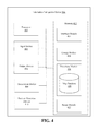
- FIG. 4 illustrates a typical telematics-navigation device in accordance with one embodiment of the present application.
- FIG. 5 illustrates a typical charging unit in accordance with one embodiment of the present application.
- FIG. 6 illustrates a typical tracking server in accordance with one embodiment of the present application.
- FIG. 7 illustrates a flowchart for a typical EV charging method in accordance with one embodiment of the present application.
- FIG. 8 illustrates a flowchart for a typical EV charging method in accordance with one embodiment of the present application.
- Certain aspects of the embodiments include process steps and instructions described herein in the form of an algorithm.
- the process steps and instructions of the embodiments may be embodied in software, firmware or hardware, and when embodied in software, may be downloaded to reside on and be operated from different platforms used by a variety of operating systems.
- the embodiments also relate to an apparatus for performing the operations herein.
- This apparatus may be specially constructed for the required purposes, or it may be a general-purpose computer selectively activated or reconfigured by a computer program stored in the computer.
- a computer program may be stored in a non-transitory computer readable storage medium, such as, but is not limited to, any type of disk including floppy disks, optical disks, CD-ROMs, magnetic-optical disks, read-only memories (ROMs), random access memories (RAMs), EPROMs, EEPROMs, magnetic or optical cards, application specific integrated circuits (ASICs), or any type of media suitable for storing electronic instructions, and each coupled to a computer system bus.
- the computers referred to in the specification may include a single processor or may be architectures employing multiple processor designs for increased computing capability.
- FIG. 2 illustrates a representative charging and discharging behavior of an EV in accordance with one embodiment of the present application.
- Chart 200 illustrates an exemplary charging cycle for an EV, when the EV is being charged using, for example, a Vehicle-to-Grid (V2G) mode.
- V2G Vehicle-to-Grid
- the EV can have a charge level 214 (around 95%) at hour 0.
- the EV can discharge to a minimum level of SOC, for example, by discharging or providing power to the electrical grid it is connected to a minimum level of SOC 202 .
- the EV is connected to a charger at hour 0 may have a SOC lower than the minimum level of SOC 202 and is charged by the charger until the SOC of the EV is greater than or equal to the minimum SOC 202 .
- An EV may discharge even when not being driven due to demands of various components of the EV, for example, the clock and the like.
- the EV charges and discharges in small increments once the EV's SOC exceeds the minimum level of SOC.
- the small incremental charging and discharging may be reflected by the small rapid variations in the amplitude by a waveform arising from fluctuations in the state of charge or jitters 206 as illustrated in FIG. 2 .
- the EV may have a maximum level of SOC, for example, 100%, 95%, 90%, or the like.
- a grid aggregator may utilize the capacity of the EV to store energy excesses 208 over an operational window 212 .
- the operational window 212 may be referred to as a float or range.
- the operational window 212 includes the EV charge storing capacity between the minimum SOC and the threshold.
- AC Alternating Current
- the grid supplier may shed (discharge) or store the excess energy. By storing the excess energy in the EV, energy waste may be minimized.
- the minimum SOC 202 is lowered, for example, to 60% as compared to the prior art minimum SOC of 95%.
- the lowered minimum SOC 202 may provide a larger operational window 212 between the maximum SOC 204 and the minimum SOC 202 .
- the larger operational window 212 may allow a grid aggregator to use the EV capability to store energy excesses 208 for longer periods.
- the operational window 212 may encompass the whole range between the minimum SOC 202 and the maximum SOC 204 .
- the operational window 212 may encompass some of the range between the minimum SOC 202 and the maximum SOC 204 , for example, the operational window 212 may be 20%—between the minimum SOC 202 of 60% and a threshold 220 less than the maximum SOC 204 of 100%—wherein the threshold 220 for the operational window 212 is set at 80% of SOC.
- the SOC within the operational window 212 may be used for or contribute to grid stabilization by providing opportunities to store energy excesses 208 from the grid.
- the operational window 212 may absorb excess charges from the grid to stabilize the grid, i.e., when grid capacity exceeds the minimum level of SOC 202 .
- the minimum SOC 202 may be set to an amount required to travel in case of certain conditions, for example, if the user has to drive to a hospital for an emergency or to travel to/from local stores. Different minimal SOC levels may be used depending on situations in which the driver would be driving outside their “normal” conditions.
- the minimum level of the SOC 202 of an EV may be determined by the vehicle, the vehicle user, the aggregator, or a combination.
- the maximum level of SOC 204 of an EV may be determined by the vehicle, the vehicle user, the aggregator, or a combination.
- the vehicle owner may get revenue by allowing the vehicle to be used for energy storage.
- a lower minimum SOC 202 provides for discharging an EV to the lower minimum SOC 202 , for example, 60%, then a conventional higher minimum SOC (see, FIG. 1 illustrating a minimum SOC of 95% as noted above) at least until a predetermined time of day, for example, midnight.
- a predetermined time of day for example, midnight.
- the V2G system is afforded a larger charging window.
- the EV is afforded a larger operating window when the minimum SOC 202 is set to, for example, 60%, and the maximum SOC 204 is set to, for example, 80%.
- the EV operates with a 20% operational window rather than the 5% operational window (see, FIG. 1 ) when the minimum SOC is 95%, the maximum SOC is 100%, and the operation window is merely 5%.
- the EV needs to charge less frequently.
- the frequency of charging is reduced the EV may be charged at more optimal times, for example, when the utility costs to the EV user are lower, when a black/brownout is neither imminent nor in effect, or the like.
- FIG. 3 illustrates a typical vehicle communication environment in accordance with one embodiment of the present application.
- FIG. 3 illustrates a vehicle communication environment 300 including an electric vehicle (EV) 302 , a tracking server 312 , and a utility server 314 connected by a wireless communication network 316 .
- EV electric vehicle
- the EV 302 includes an electric motor (not shown) for propulsion of the vehicle 302 .
- the EV 302 may be propelled by one or more electric motors.
- the EV 302 may be propelled by one or more electric motors and another engine, for example, an internal combustion engine or a plug-in hybrid electric vehicle.
- the one or more electric motors of the EV 302 may be powered by rechargeable batteries (not shown) on-board the vehicle 302 .
- the on-board batteries may be charged when the EV 302 is connected or coupled to a charging station.
- the EV 302 may be connected to a charging station 310 via a charging cable 318 .
- the EV 302 may be charged wirelessly, for example, by disposing the EV 302 proximate or adjacent to the charging station 310 .
- the charging station 310 provides electric energy to the EV 302 , for example, by charging or recharging the batteries of the EV.
- the electric energy may be supplied to the charging station 310 by a utility company through an electrical grid.
- the charging station 310 may be connected to a 110/120 volt circuit, a 220/240 volt circuit, or a higher voltage circuit. In exemplary embodiments, the charging station 310 may be located at a home of the EV's owner. In exemplary embodiments, the charging station 310 may be a public location, for example, a workplace, a shopping center, a charging service, or the like. In exemplary embodiments, the on-board batteries may be charged using regenerative braking.
- the EV 302 includes a charging system 304 that manages the charging of the EV 302 .
- the charging system 304 includes a telematics-navigation device 306 and a control unit 308 .
- the telematics-navigation device 306 may exchange information with users of the telematics-navigation device 306 and entities connected to the wireless communication network 316 .
- the telematics-navigation device 306 may receive charging instructions from a user when the EV 302 is connected to a charging station. There may be multiples modes or strategies for charging the EV 302 .
- the telematics-navigation device 306 may communicate with the utility server 314 to obtain information on electric energy, such as, the cost of the electric energy, whether the energy was generated using a renewable energy source (e.g., sunlight, wind or tides), and the like.
- a renewable energy source e.g., sunlight, wind or tides
- the telematics-navigation device 306 may provide charging information to the tracking server 312 .
- the control unit 308 controls the charging of the EV 302 .
- Charging the EV 302 includes the charging of the EV's rechargeable batteries.
- the control unit 308 determines a strategy for charging the EV 302 based on a charging mode selected by a user. The control until 308 charges the EV according to the determined strategy.
- a user may select an “economic” charging mode.
- the control unit 308 may initiate the charging of the EV 302 by allowing electric energy to flow to the EV 302 from the charging station.
- the control unit 308 may initiate the charging regardless of the current cost of electric energy.
- the control unit 308 may allow the EV 302 to charge until the state of charge of the EV 302 reaches a minimum state of charge.
- the term “state of charge” refers to the amount of electric charge/energy stored in the EV's batteries.
- the control unit 308 halts the charging of the EV 302 by stopping the flow of electric energy from the charging station to the EV 302 .
- the control unit 308 may reinitiate the charging of the EV 302 when the cost of electric energy is economical, such as, during off-peak times.
- the minimum state of charge may be determined by the user or may be determined by the control unit 308 based, for example, on a usage pattern.
- the minimum state of charge may be set such that it is enough, for example, to go to a nearby grocery store, run an errand or the like, and return home.
- One benefit of the economic mode is that it allows the EV 302 to receive some charge to prevent a driver from being stranded while at the same time allowing most of the charging to occur when electric energy is economical.
- a user may select a “green” charging mode.
- Green mode is similar to economic mode except that the control unit 308 reinitiates the charging of the EV 302 when electric energy provided to the charging station is being generated using a renewable energy source.
- the utility server 314 provides information about electric energy to different entities.
- the utility server 314 upon request from the EV 302 , transmits to the EV 302 identifying information about electric energy supplied by a utility company.
- information transmitted by the utility server 314 to the EV 302 upon request includes rate information, such as, time periods when the electric energy provided by the utility company at off-peak costs, generated by a renewable source and the like.
- information transmitted to the EV 302 includes cost information for the electric energy.
- the cost information is Time of Use (TOU) rates where the rates for electric energy vary based on time, day, month, and/or season.
- TOU Time of Use
- the cost information for electric energy during summer months may be $0.14 per KWh during peak hours (e.g., 12 PM to 7 PM), $0.07 per KWh during part-peak hours (e.g., 10 AM to 12 PM and 7 PM to 10 PM), and $0.03 per KWh during non-peak hours (e.g., 12:00 AM to 10 AM and 10 PM to 11:59 PM).
- a request from the EV 302 received by the utility server 314 includes identifying information of the EV 302 (e.g., vehicle identification number (VIN) of the EV 302 ) and/or identifying information of the owner (e.g., owner's name or address) so that the utility server 314 provides accurate cost information to the EV 302 .
- identifying information of the EV 302 e.g., vehicle identification number (VIN) of the EV 302
- identifying information of the owner e.g., owner's name or address
- the utility server 314 receives requests from the tracking server 312 for total electric energy storage capacity of sectors. For a requested sector, the utility server 314 transmits to the tracking server 312 the current total electric energy storage capacity of the sector.
- the total electric energy storage capacity of a sector includes the total electric energy storage available from the EVs in the sector. Entities may include charging stations, homes, and businesses.
- the utility server 314 also transmits information on the total electric energy consumption and/or storage capacity of a sector to the EV 302 .
- the utility server 314 is maintained by a utility company. In exemplary embodiments, the utility server 314 is maintained by a third-party that obtains information from one or more utility companies.
- the wireless communication network 316 represents a communication pathway between the EV 302 , the tracking server 312 , and the utility server 314 .
- the wireless communication network 316 is a cellular network including multiple base stations, controllers, and a core network including multiple switching entities and gateways.
- the wireless communication network 316 is a Wireless Local Area Network (WLAN) that provides wireless communication over a limited area.
- the WLAN includes an access point that connects the WLAN to the Internet.
- a telematics-navigation device 306 includes a processor 402 , an input device 404 , an output device 406 , a transceiver device 408 , a position detection device 410 , and a memory 412 .
- the processor 402 processes data signals and includes various computing architectures including a complex instruction set computer (CISC) architecture, a reduced instruction set computer (RISC) architecture, or an architecture implementing a combination of instruction sets. Although only a single processor is illustrated in FIG. 4 , multiple processors may be included.
- the processor 402 includes an arithmetic logic unit, a microprocessor, a general purpose computer, or some other information appliance equipped to transmit, receive and process electronic data signals from the memory 412 , the input device 404 , the output device 406 , the transceiver device 408 , or the position detection device 410 .
- the input device 404 is configured and arranged to provide user input to the telematics-navigation device 306 .
- Exemplary input device 404 may include a cursor controller, a keyboard, a touchscreen device, a microphone, a haptic feedback device, or the like.
- the input device 404 may include an alphanumeric input device, such as, a QWERTY keyboard, a key pad or representations of such created on a touch screen, configured and arranged to communicate information and/or command selections to processor 402 or memory 412 .
- the input device 404 may include a user input device to communicate positional data and/or command selections to processor 402 .
- the input device 404 may include a joystick, a mouse, a trackball, a stylus, a pen, a touch screen, cursor direction keys or the like to cause movement adjustment of an image.
- the output device 406 includes a device configured and arranged to display electronic images and data as described herein.
- Output device 406 may include, for example, an organic light emitting diode display (OLED), liquid crystal display (LCD), cathode ray tube (CRT) display, or the like.
- OLED organic light emitting diode display
- LCD liquid crystal display
- CRT cathode ray tube
- output device 406 may include a touch-sensitive touch screen including a transparent panel cover disposed over or integrated with the screen of output device 406 .
- the output device 406 includes a speaker that outputs audio as described herein.
- the transceiver device 408 includes a device configured and arranged to communicate with entities connected to the wireless communication network 316 .
- the telematics-navigation device 306 uses the transceiver device 408 to communicate with remote systems or devices, such as, the tracking server 312 and the utility server 314 .
- the position detection device 410 includes a device configured and arranged to communicate with a positioning satellite (e.g., global positioning system (GPS) satellites) to determine a geographical location of the EV 302 .
- a positioning satellite e.g., global positioning system (GPS) satellites
- GPS global positioning system
- the position detection device 410 searches for and collects GPS information or signals from three, four or more GPS satellites to determine the location of the EV 302 .
- the position detection device 410 may calculate the distance between the EV 302 and each of the GPS satellites. These distance measurements, along with the position and time information received in the signals, allow the position detection device 410 to calculate or determine the geographical location and/or attitude of the EV 302 .
- the memory 412 stores instructions and/or data that may be executed by processor 402 .
- the instructions and/or data may code for performing any and/or all of the techniques described herein.
- Memory 412 may be a Dynamic Random Access Memory (DRAM) device, a Static Random Access Memory (SRAM) device, Flash RAM (non-volatile storage), combinations of the above, or some other memory device known in the art.
- the memory 412 may store an interface module 414 , an energy module 416 , a directions module 418 , and a range module 422 .
- the modules may communicate with the processor 402 , the input device 404 , the output device 406 , the transceiver 408 , and/or the position detection device 410 .
- the interface module 414 communicates with users of the telematics-navigation device 306 .
- the interface module 414 receives from a user (e.g., a driver or passenger of the EV 302 ) a selection of a mode for charging the EV 302 when the EV 302 is connected to a charging station.
- the modes that a user may select from may include one or more of the following: “charge now” mode, “timer” mode, “economical” mode, and “green” mode.
- the EV 302 begins to charge immediately once it is connected to a charging station and continues to charge until the EV 302 is fully charged.
- the user provides the interface module 414 with a time to begin charging. At the time provided, the EV 302 begins to charge.
- the EV is charged to a minimum state of charge. Once the minimum state of charge is reached, the charging is halted. In exemplary embodiments, the minimum state of charge may be set by the manufacturer of the EV 302 (e.g., 10 percent, 20 percent, enough to drive for 10 miles, 20 miles, 30 miles, 60 miles etc.). In exemplary embodiments, a user provides or sets the interface module 414 with the minimum state of charge. The charging is resumed when electric energy is economical. In exemplary embodiments, economical is when the cost of energy is below peak hour cost (e.g., cost during part-peak and off-peak hours). Peak hours are when there is the highest demand for electric energy on an electrical grid. In exemplary embodiments, economical is the cost of energy during off-peak hours. In exemplary embodiments, a user provides or sets the interface module 414 with a price range for what is considered economical.
- peak hour cost e.g., cost during part-peak and off-peak hours. Peak hours are when there is the highest demand for electric energy on an electrical grid.
- the EV 302 Under green mode, the EV 302 is charged to a minimum state of charge and the charging is then halted. The charging is resumed when electric energy supplied to the charging station is generated using a renewable energy source.
- the interface module 414 communicates with a user via the input device 404 and output device 406 .
- the interface module 414 may communicate and in with a user via a mobile device of the user to the wireless communication network 316 .
- the mobile device may include an application that allows the user to select the charge mode and provide settings for each mode. The mobile device transmits to the interface module 414 the user's selections and settings.
- the energy module 416 obtains information on electric energy from the utility server 314 .
- the information that the energy module 416 obtains from the utility server 314 includes cost information for electric energy, times when electric energy is generated using a renewable energy source, information on the total electric energy consumption of one or more sectors, or information on the total electric energy storage capacity of one or more sectors.
- the cost information obtained by the energy module includes current time of use rates for electric energy.
- the energy module 416 periodically requests electric energy information from the utility server 314 . For example, information may be requested every day, once a month, or once per calendar season. In exemplary embodiments, the energy module 416 requests electric energy information from the utility server 314 every time the EV 302 is connected to a charging station. When the energy module 416 receives electric energy information from the utility server 314 , the energy module 416 may provide the information to the control unit 308 .
- the directions module 418 provides a user of the EV 302 with driving directions to a destination.
- the directions module 418 obtains the current geographic location of the EV 302 from the position detection module 410 .
- the directions module 418 uses one or more maps stored in a map database 420 to identify routes from the current location of the EV 302 to the destination.
- the range module 422 determines the driving range of the EV 302 .
- the range of the EV 302 includes the distance that the EV 302 may travel before it no longer has energy to travel.
- FIG. 5 illustrates a typical charging unit in accordance with one embodiment of the present application.
- the control unit 308 includes a processor 502 and a memory 504 .
- the processor 502 and memory 504 may be functionally equivalent to the processor 402 and memory 412 of the telematics-navigation device 306 .
- the memory 504 may include an information module 506 , a charging module 508 , and a notification module 510 .
- the information module 506 provides charging information to the tracking server 312 .
- the information module 506 periodically (e.g., every 15 minutes) transmits charging information to the tracking server 302 .
- the information module 506 transmits charging information to the tracking server 312 when the EV 302 starts charging and when the charging stops.
- the charging information transmitted to the tracking server 312 by the information module 506 includes one or more of the following: the current time, time when charging started, time when charging stopped, the current geographic location of the EV 302 , a VIN of the EV 302 , information about the owner of the E.V. (e.g., owner's identifier, name or address), information about the charging station (e.g., voltage at the charging station), the current flow, the current state of charge of the EV 302 , combination thereof, or the like.
- Charging module 508 manages the charging of the EV 302 .
- the charging module 508 determines a strategy for charging the EV 302 based at least on a charging mode selected by a user through the telematics-navigation device 306 .
- the strategy determined by the charging module 508 for charging the EV 302 includes the charging module 508 immediately initiating the charging of the EV 302 .
- the charging module 508 simply allows electric energy from the charging station to flow to the EV 302 .
- the charging cable includes a data connection to the charging station and to initiate charging, the charging module 508 sends a signal to the charging station for it to start transmitting electric energy.
- the charging module 508 signals the station to stop the transmission of electric energy.
- the charging module 508 allows the EV 302 to continue charging until the EV 302 is fully charged. The charging module 508 maintains the EV 302 fully charged until the EV 302 is disconnected from the charging station.
- the strategy determined by the charging module 508 for charging the EV 302 identifies a set time associated with the timer mode and provided to the telematics-navigation device 506 .
- the charging module 508 tracks the current time.
- the charging module 508 initiates charging of the EV 302 .
- the charging module 508 allows the EV 302 to continue charging until the EV 302 is fully charged.
- the charging module 508 allows the EV 302 to charge until the stop time is reached or the EV 302 is fully charged, whichever occurs first.
- the strategy determined by the charging module 508 for charging the EV 302 includes the charging module 508 determining whether the current state of charge of the EV 302 is less than a minimum state of charge. If the current state of charge is below the minimum state of charge, the charging module 508 initiates the charging of the EV 302 regardless of the current cost of electric energy. The charging module 508 halts the charging of the EV 302 once the state of charge of the EV 302 reaches the minimum state of charge.
- the minimum state of charge is an amount that is less than the EV 302 being fully charged.
- the charging module 508 determines a time for reinitiating the charging based on the latest cost information obtained by telematics-navigation device 306 from the utility server 314 .
- the charging module 508 determines to reinitiate charging at the closest time when the cost of electric energy is economical.
- the charging module 508 reinitiates charging of the EV 302 at the determined time.
- the charging module 508 allows the charging of the EV 302 to continue as long as the electric energy being transmitted by the charging station is economical and until the EV 302 is fully charged.
- the charging module 508 if the charging module 508 receives charging instructions from the tracking server 312 , instead of charging according to the strategy determined by the charging module 508 , the charging module 508 charges the EV 302 according to the instructions received from the tracking server 312 . In other words, the instructions received from the tracking server 312 may override the strategy determined by the charging module 508 for charging the EV 302 .
- the notification module 510 transmits messages to a user of the EV 302 .
- the notification module 510 sends a message with information as to how the EV 302 will be charged according to the instructions. For example, if instructions received from the tracking server 312 indicate to delay charging for two hours, the notification module 510 sends a message to the user that states that charging of the EV 302 will be delayed by two hours. Based on information received from the tracking server 312 , the notification module 510 additionally includes in the message an explanation of why the EV 302 is being charged according to instructions from the tracking server 312 .
- the explanation may be that the excess capacity of the EV will be used to store excess electric energy.
- the notification module 510 transmits messages to the user when one or more of the following occurs: when the charging module 508 initiates the charging of the EV 302 , when charging of the EV is stopped, and when the EV 302 has reached full charge.
- messages are transmitted by the notification module 510 to the user's mobile device as short message service (SMS) messages or multimedia messaging service (MMS) messages.
- SMS short message service
- MMS multimedia messaging service
- messages are transmitted by notification module 510 to the user's mobile device and appear on the mobile device as part of a mobile application that provides information about the EV 302 .
- messages are transmitted to the user's email address as emails.
- FIG. 6 illustrates a typical tracking server in accordance with one embodiment of the present application.
- the tracker server 314 includes a processor 602 and a memory 604 .
- the processor 602 and memory 604 are functionally equivalent to the processor 402 and memory 412 of the telematics-navigation device 306 .
- the memory 604 stores a vehicle module 606 , an energy Storage module 608 , and a strategy module 610 .
- the vehicle module 606 tracks EVs charging in different sectors.
- the vehicle module 606 maintains a list of EVs charging in each sector.
- the vehicle module 606 identifies from the charging information a current geographical location of the EV and a sector associated with the EV's geographical location.
- the vehicle module 606 determines whether the EV is included in the list. If the EV is not included, the vehicle module 606 adds the EV to the list (e.g., the VIN of the EV) under the identified sector along with charging information received. If the EV is already included in the list, the vehicle module 606 updates charging information included in the list for the EV based on the last information received. For example, if the current state of charge of the EV is 70% and the list indicates that it is 30%, the vehicle module 606 will update the list to indicate that it is 70%.
- the vehicle module 606 When an EV transmits charging information that indicates that the charging of the EV has stopped, the vehicle module 606 identifies the sector associated with the EV's current location. The vehicle module 606 removes the EV under the identified sector from the list.
- the energy storage module 608 tracks electric energy storage capacity for sectors. For each sector, the energy storage module 608 periodically requests and receives (e.g., every 30 minutes) from the utility server 314 the current total electric energy storage needs of the sector. The energy storage module 608 tracks the current electric energy excess generation of each of the sectors based on the information received from utility server 314 .
- the strategy module 610 when necessary controls the charging of EVs to provide electric energy storage capacity for sectors.
- the strategy module 610 obtains from the vehicle module 606 information on EVs charging in the sector.
- the strategy module 610 determines a strategy for efficiently charging the EVs in the sector in a way that will permit storage of electric energy in the EVs in the sector.
- the strategy determined by the strategy module 610 is to reduce the rate at which electric energy is being shed or stored in one or more of the EVs in the sector by their respective charging stations.
- the strategy is to stagger the storing of the electric charge in EVs in the sector so that the EVs stay below the maximum SOC set for the EV.
- the strategy consists of the strategy module 610 determining a schedule for each EV in the sector that is charging. The schedule indicates when the EV is to charge and for how long.
- the EVs with higher range of operational windows of charge get the earlier charging times and are allowed to store electric energy for longer periods, whereas the EVs that with smaller or narrower operational windows of charge get the later times.
- a strategy determined by the strategy module 610 that is more drastic is to store electric charge in all the EVs in the sector.
- the strategy module 610 transmits instructions for charging to the appropriate EVs in the sector based on the determined strategy.
- the instructions describe to an EV how the EV should be charged.
- the transmitted instructions allow the EVs to execute the strategy determined by the strategy module 610 .
- the strategy module 610 transmits with the instructions information as to why the strategy is being put into effect (e.g., because current electric energy consumption is less than current electric generation availability).
- the threshold for each sector varies.
- the threshold may be electricity generation that exceeds electricity consumption by 5%, 10%, 15%, 20% or greater.
- the one or more thresholds of a sector are set by a utility company that provides electric energy to the sector.
- FIG. 7 illustrates a flowchart for a typical EV charging method in accordance with one embodiment of the present application.
- Method 700 may be performed by the charging system 304 for charging the EV 302 .
- the steps of the method are implemented by the processors of the telematics-navigation device 306 and the control unit 308 executing instructions that cause the desired actions.
- the processors of the telematics-navigation device 306 and the control unit 308 executing instructions that cause the desired actions.
- identifying information for electric energy is received at operation 702 .
- the identifying information of the electric energy may include a SOC of the EV, a minimum SOC level for the EV, a maximum SOC level for the EV, an operational window, a threshold, a utility rate, a forecasted time of use for the EV, electricity supply information, electricity demand information, information for electric energy supplied to the charging station and the like.
- the identifying information of the electric energy may be provided by EV.
- one or more parameters included in the identifying information of the electric energy may be supplied by a grid operator, for example, by a utility server.
- one or more parameters included in the identifying information of the electric energy may be supplied be an aggregator, in other words, a commercial charging station used to energize multiple electric vehicles at one time.
- the minimum level of SOC may be set be to range between 20% of a vehicle maximum capacity charge level to 90% of, for example, 20% or greater, 25% or greater, 30% or greater, 35% or greater, 40% or greater, 45% or greater, 45% or greater, 50% or greater, 55% or greater, 60% or greater, 65% or greater, 70% or greater, 75% or greater, 80% or greater, 85% or greater, or the like.
- the maximum level of SOC may be set be to range between 50% of a vehicle maximum capacity charge level to 90% of a vehicle maximum capacity charge level, for example, 50% or greater, 55% or greater, 60% or greater, 65% or greater, 70% or greater, 75% or greater, 80% or greater, 85% or greater, 90% or greater, 95% or greater, or the like.
- the float e.g., the operational window between a minimum level of SOC and a threshold of SOC, may provide for storing a charge on behalf of the grid.
- the operational window may range from 10% of a vehicle maximum capacity charge level to 70% of a vehicle maximum capacity charge level, for example, 10% or greater, 15% or greater, 20% or greater, 25% or greater, 30% or greater, 35% or greater, 40% or greater, 45% or greater, 45% or greater, 50% or greater, 55% or greater, 60% or greater, 65% or greater, 70% or greater, or the like.
- the charger may initiate charging of the electric vehicle at operation 704 to, for example, ensure that the EV SOC exceeds a minimum state of charge.
- the method 700 may monitor the charge vehicle operation 706 . When the monitoring determines that the EV has been charged to a minimum state of charge at operation 708 , a halt of the charging of the EV at operation 710 is performed.
- method 700 may calculate or receive a determination of a time to reinitiate the charging of the vehicle based on the identifying information of the electric energy at operation 712 .
- the determination of a time to reinitiate the charging of the vehicle based on the identifying information of the electric energy at operation 712 may further include notifying the grid that the EV is available to store grid energy at least until it is time to reinitiate the charging of the EV. In exemplary embodiments, the determination of a time to reinitiate the charging of the vehicle based on identifying information for the electric energy at operation 712 may further include notifying the grid that the EV is available to store grid energy at most until a forecasted time of use for the EV.
- method 700 may include receiving a request from a grid or an aggregator to store charge at operation 714 .
- method 700 may include charging electric vehicles to the maximum state of charge or a SOC level specified by the grid at operation 716 .
- Method 700 may include recording user revenue at operation 717 .
- the revenue may be based on the duration of the storage of the charge and a maximum charge level of the EV based on a grid request to store energy.
- the user revenue may be computed or received.
- the user revenue may be recorded with the identifying information of the electric energy.
- method 700 may include reinitiate charging of the vehicle at operation 718 .
- method 700 may re-determine or re-compute a time to reinitiate charge based on current state of charge 720 .
- method 700 may make the EV available for storing energy to the grid per operation 714 .
- the charging system 304 identifies information for electric energy supplied to the charging station. The information is provided to the charging system 304 by the utility server 314 . The charging system 304 initiates 704 charging of the EV 302 regardless of the current cost of the electric energy.
- the charging system 304 allows the EV 302 to continue charging 706 until the state of charge of the EV 302 reaches a minimum state of charge.
- the charging system 304 halts 708 the charging of the EV 302 once the state of charge of the EV 302 reaches the minimum state of charge.
- the charging system 304 determines 712 a time for reinitiating charging of the EV 302 based on the information.
- the charging system 304 reinitiates 718 charging of the EV 302 at the determined time.
- FIG. 8 illustrates a flowchart for a typical EV charging method in accordance with one embodiment of the present application.
- Method 800 may be performed by the charging system 304 for charging the EV 302 .
- the steps of the method are implemented by the processors of the telematics-navigation device 306 and the control unit 308 executing instructions that cause the desired actions.
- the processors of the telematics-navigation device 306 and the control unit 308 executing instructions that cause the desired actions.
- the processors of the telematics-navigation device 306 and the control unit 308 executing instructions that cause the desired actions.
- the steps of the method steps may be implemented in embodiments of hardware and/or software or combinations thereof.
- instructions for performing the described actions are embodied or stored within a non-transitory computer readable medium.
- other embodiments may perform the steps of FIG. 8 in different orders.
- other embodiments may include different and/or additional steps than the ones described here.
- the identifying information of the electric energy may include a SOC of the EV, a minimum SOC level for the EV, a maximum SOC level for the EV, an operational window, a threshold, a utility rate, a forecasted time of use for the EV, electricity supply information, electricity demand information, information for electric energy supplied to the charging station and the like.
- the identifying information of the electric energy may be provided by EV.
- one or more parameters included in the identifying information of the electric energy may be supplied by a grid operator, for example, by a utility server.
- one or more parameters included in the identifying information of the electric energy may be supplied be an aggregator, in other words, a commercial charging station used to energize multiple electric vehicles at one time.
- the minimum level of SOC may be set be to range between 20% of a vehicle maximum capacity charge level to 90% of, for example, 20% or greater, 25% or greater, 30% or greater, 35% or greater, 40% or greater, 45% or greater, 45% or greater, 50% or greater, 55% or greater, 60% or greater, 65% or greater, 80% or greater, 85% or greater, 80% or greater, 85% or greater, or the like.
- the maximum level of SOC may be set be to range between 50% of a vehicle maximum capacity charge level to 90% of a vehicle maximum capacity charge level, for example, 50% or greater, 55% or greater, 60% or greater, 65% or greater, 70% or greater, 75% or greater, 80% or greater, 85% or greater, 90% or greater, 95% or greater, or the like.
- the float e.g., the operational window between a minimum level of SOC and a threshold of SOC, may provide for storing a charge on behalf of the grid.
- the operational window may range from 10% of a vehicle maximum capacity charge level to 70% of a vehicle maximum capacity charge level, for example, 10% or greater, 15% or greater, 20% or greater, 25% or greater, 30% or greater, 35% or greater, 40% or greater, 45% or greater, 45% or greater, 50% or greater, 55% or greater, 60% or greater, 65% or greater, 70% or greater, or the like.
- the charger may maintain a charge of the electric vehicle at operation 804 to, for example, ensure that the EV SOC is within an operational window.
- the EV may be allowed to discharge to the minimum SOC, when the current SOC of the EV exceeds a minimum SOC per operation 808 .
- the EV may be charged to the minimum SOC, when the current SOC of the EV is less than the minimum SOC per operation 808 .
- the maintaining of the charge of the EV that needs to charge the EV above the minimum SOC can be performed during a low cost window in operation 810 .
- method 800 may calculate or receive a determination of a time to initiate the charging of the vehicle to the maximum SOC based on the identifying information of the electric energy at operation 812 .
- the determination of the time to initiate the charging of the vehicle to the maximum SOC based on the identifying information of the electric energy at operation 812 may further include notifying the grid that the EV is available to store grid energy at least until it is time to initiate the charging of the EV to the maximum SOC. In exemplary embodiments, the determination of a time to initiate the charging of the vehicle at operation 812 may further include notifying the grid that the EV is available to store grid energy until a forecasted time of use for the EV.
- method 800 may include receiving a request from a grid or an aggregator to store charge at operation 814 . As such, method 800 may include charging electric vehicles to the threshold or a SOC level specified by the grid at operation 816 .
- Method 800 may include recording user revenue at operation 817 .
- the revenue may be based on the duration of the storage of the charge and a maximum charge level of the EV based on a grid request to store energy.
- the user revenue may be computed or received.
- the user revenue may be recorded with the identifying information of the electric energy.
- Method 800 may include recording utility revenue at operation 819 .
- the utility revenue may be based on a discounted cost for the electrical energy stored for the electrical grid's use in the vehicle and which electrical energy was not discharged by the electrical grid prior to the time for initiating the charging to the maximum SOC in the vehicle elapsed.
- method 800 may include initiate charging to the maximum SOC of the vehicle at operation 818 .
- method 800 may re-determine or re-compute a time to initiate charge vehicle to the maximum SOC based on current state of charge 820 .
- method 800 may make the EV available for storing energy to the grid per operation 814 .
- the information identified is information that describes the cost of electric energy at different times of a day.
- the time when charging is reinitiated is a time when electric energy is economical or the determined time to charge to maximum SOC has arrived.
- Method 800 may include calculating total electricity consumption and generation in a sector in operation 830 .
- Method 800 may include tracking a storage capacity or operational window value of each EV connected to a charger in a sector at operation 832 .
- An EV may be available to store excess grid capacity once the EV has reached the minimum SOC for the vehicle.
- operation 834 can select and determine a strategy to store the grid's excess energy for each EV that was tracked as being connected and having a storage capacity in the sector at operation 832 .
- method 800 includes transmitting the determined strategy for each selected vehicle in the sector in order for the selected vehicles to start storing excess electricity on behalf of the grid.
- the above-described embodiments according to the present disclosure may be implemented in the form of a program command that may be executed through various constituent elements of a computer, and the program command may be recorded on a computer-readable recording medium.
- the above-described computer-readable recording medium may independently include a program command, a data file, a data structure, or the like or may include a combination thereof.
- the program command recorded on the computer-readable recording medium is designed and configured especially for the present disclosure and may be known to those skilled in the art in the field of computer software to be usable.
- Examples of the computer-readable recording medium include a magnetic medium such as a hard disk, a floppy disk, or a magnetic tape, an optical recording medium such as a CD-ROM or a DVD, a magneto-optical medium such as a floptical disk, and a hardware device such as a ROM, a RAM, or a flash memory that is especially configured so as to store and execute the program command.
- Examples of the program command include not only a machine code that is produced by a complier but also a high-level language code that may be executed by a computer using an interpreter or the like.
- the above-described hardware device may be configured to operate as one or more software modules used for performing the process according to the present disclosure, and the program command may be implemented as one or more hardware devices.
Landscapes
- Engineering & Computer Science (AREA)
- Power Engineering (AREA)
- Transportation (AREA)
- Mechanical Engineering (AREA)
- Life Sciences & Earth Sciences (AREA)
- Sustainable Development (AREA)
- Sustainable Energy (AREA)
- Charge And Discharge Circuits For Batteries Or The Like (AREA)
- Electric Propulsion And Braking For Vehicles (AREA)
- Supply And Distribution Of Alternating Current (AREA)
Priority Applications (3)
| Application Number | Priority Date | Filing Date | Title |
|---|---|---|---|
| US14/214,318 US9457680B2 (en) | 2013-11-15 | 2014-03-14 | Vehicle-to-grid control |
| DE102014223284.8A DE102014223284B4 (de) | 2013-11-15 | 2014-11-14 | Fahrzeug-zu-netzregelung / -steuerung |
| JP2014232067A JP6285848B2 (ja) | 2013-11-15 | 2014-11-14 | 車両と電力系統間の制御 |
Applications Claiming Priority (2)
| Application Number | Priority Date | Filing Date | Title |
|---|---|---|---|
| US201361904458P | 2013-11-15 | 2013-11-15 | |
| US14/214,318 US9457680B2 (en) | 2013-11-15 | 2014-03-14 | Vehicle-to-grid control |
Publications (2)
| Publication Number | Publication Date |
|---|---|
| US20150137752A1 US20150137752A1 (en) | 2015-05-21 |
| US9457680B2 true US9457680B2 (en) | 2016-10-04 |
Family
ID=53172642
Family Applications (1)
| Application Number | Title | Priority Date | Filing Date |
|---|---|---|---|
| US14/214,318 Active 2035-02-18 US9457680B2 (en) | 2013-11-15 | 2014-03-14 | Vehicle-to-grid control |
Country Status (3)
| Country | Link |
|---|---|
| US (1) | US9457680B2 (enExample) |
| JP (1) | JP6285848B2 (enExample) |
| DE (1) | DE102014223284B4 (enExample) |
Cited By (11)
| Publication number | Priority date | Publication date | Assignee | Title |
|---|---|---|---|---|
| US20160087432A1 (en) * | 2014-07-04 | 2016-03-24 | Stefan Matan | Local metering response to data aggregation in distributed grid node |
| US10661678B2 (en) | 2018-09-26 | 2020-05-26 | Inventus Holdings, Llc | Curtailing battery degradation of an electric vehicle during long-term parking |
| US10686314B2 (en) | 2014-07-04 | 2020-06-16 | Xslent Energy Technologies, Llc | Power grid saturation control with distributed grid intelligence |
| US10879695B2 (en) | 2014-07-04 | 2020-12-29 | Apparent Labs, LLC | Grid network gateway aggregation |
| US11192466B2 (en) | 2018-10-01 | 2021-12-07 | Honda Motor Co., Ltd. | Electric charge management system and method for a vehicle |
| US11381101B1 (en) * | 2021-10-06 | 2022-07-05 | Geotab Inc. | Systems for vehicle battery charging around charge-adverse time periods |
| US20220332216A1 (en) * | 2020-06-24 | 2022-10-20 | Panasonic Intellectual Property Corporation Of America | Control method, control device, and non-transitory computer readable storage medium |
| US20230063011A1 (en) * | 2021-08-31 | 2023-03-02 | Subaru Corporation | Vehicle |
| US11642977B2 (en) | 2020-07-09 | 2023-05-09 | Weave Grid, Inc. | Optimized charging of electric vehicles over distribution grid |
| US12019415B2 (en) | 2022-02-24 | 2024-06-25 | Toyota Motor North America, Inc. | Grouping electric transports for an electric grid |
| US12384353B2 (en) | 2022-11-07 | 2025-08-12 | Honda Motor Co., Ltd. | Vehicle battery life management for energy solutions |
Families Citing this family (28)
| Publication number | Priority date | Publication date | Assignee | Title |
|---|---|---|---|---|
| WO2016196968A1 (en) * | 2015-06-04 | 2016-12-08 | Nec Energy Solutions, Inc. | Utilizing a load for optimizing energy storage size and operation in power systems regulation applications |
| JP6653197B2 (ja) | 2016-03-15 | 2020-02-26 | 本田技研工業株式会社 | 蓄電装置、機器及び制御方法 |
| US11108090B2 (en) | 2016-11-01 | 2021-08-31 | Honda Motor Co., Ltd. | Power storage device, transport equipment, and control method |
| WO2018084151A1 (ja) | 2016-11-01 | 2018-05-11 | 本田技研工業株式会社 | サーバ装置及び制御方法 |
| US20200023747A1 (en) * | 2017-02-22 | 2020-01-23 | Iotecha Corp. | Method and Apparatus for Charging a Battery From an Isolatable Electric Power Grid |
| JP6958286B2 (ja) * | 2017-11-24 | 2021-11-02 | トヨタ自動車株式会社 | 車両及び電力制御システム |
| JP7013864B2 (ja) * | 2017-12-28 | 2022-02-01 | トヨタ自動車株式会社 | 自動車 |
| KR102550011B1 (ko) * | 2018-05-30 | 2023-07-03 | 한국전력공사 | 전기자동차 방전속도 기반의 변전소 전원 공급 방법 및 이를 이용한 충방전기 |
| WO2020070755A1 (en) * | 2018-10-01 | 2020-04-09 | Tvs Motor Company Limited | A charger device and a method of charging using said charger device |
| CN109774501B (zh) * | 2018-12-07 | 2021-02-12 | 纳恩博(北京)科技有限公司 | 电动滑板车的充电方法、电动滑板车 |
| CN109823223B (zh) * | 2019-01-23 | 2023-12-08 | 国家电网有限公司 | 一种电动汽车充电站的储能容量配置方法及系统 |
| JP7212557B2 (ja) * | 2019-03-15 | 2023-01-25 | 本田技研工業株式会社 | 電力管理装置 |
| US11180046B2 (en) * | 2019-03-27 | 2021-11-23 | Alexander Waardenburg | Using electric vehicles for long term energy storage |
| JP2020202625A (ja) * | 2019-06-06 | 2020-12-17 | 本田技研工業株式会社 | 管理装置、管理方法、およびプログラム |
| JP7456900B2 (ja) * | 2020-09-15 | 2024-03-27 | 本田技研工業株式会社 | 電力管理装置および電力管理システム |
| KR20230067151A (ko) * | 2021-11-09 | 2023-05-16 | 현대자동차주식회사 | 차량의 충방전 제어 시스템 및 방법 |
| CN114056162B (zh) * | 2021-11-25 | 2022-11-01 | 安徽安凯汽车股份有限公司 | 一种纯电动客车充电控制系统 |
| US12472837B2 (en) * | 2022-02-21 | 2025-11-18 | Cyberswitchingpatents, Llc | Electric vehicle charging master controller |
| JP7499801B2 (ja) * | 2022-03-30 | 2024-06-14 | 本田技研工業株式会社 | 制御装置、移動体、方法及びプログラム |
| JP7503088B2 (ja) * | 2022-03-30 | 2024-06-19 | 本田技研工業株式会社 | 制御装置、移動体、方法及びプログラム |
| JP7499802B2 (ja) * | 2022-03-30 | 2024-06-14 | 本田技研工業株式会社 | 制御装置、移動体、方法及びプログラム |
| US20240055885A1 (en) * | 2022-08-15 | 2024-02-15 | Apple Inc. | Energy based task shifting |
| CN116455010A (zh) * | 2022-09-30 | 2023-07-18 | 度普(苏州)新能源科技有限公司 | 充电桩的智能充电方法、系统、电子设备及存储介质 |
| DE102022133576A1 (de) | 2022-12-16 | 2024-06-27 | Bayerische Motoren Werke Aktiengesellschaft | Verfahren zum Laden eines Elektrofahrzeugs in einem V2X-Anwendungsfall |
| WO2024201633A1 (ja) * | 2023-03-27 | 2024-10-03 | 日本電気株式会社 | 情報表示装置、情報表示方法、及び、記録媒体 |
| US20240364112A1 (en) * | 2023-04-25 | 2024-10-31 | Toyota Motor North America, Inc. | Predictive intelligence based on electrical outage trends |
| DE102023115484A1 (de) | 2023-06-14 | 2024-12-19 | Bayerische Motoren Werke Aktiengesellschaft | Verfahren zum Laden eines Elektrofahrzeugs, Elektrofahrzeug und System |
| US20250256582A1 (en) * | 2024-02-09 | 2025-08-14 | GM Global Technology Operations LLC | Predictive preparation for energy disruption event |
Citations (15)
| Publication number | Priority date | Publication date | Assignee | Title |
|---|---|---|---|---|
| US5642270A (en) | 1991-08-01 | 1997-06-24 | Wavedriver Limited | Battery powered electric vehicle and electrical supply system |
| JP2001008380A (ja) | 1999-06-17 | 2001-01-12 | Nissan Motor Co Ltd | 電力マネジメントシステム |
| US7782021B2 (en) | 2007-07-18 | 2010-08-24 | Tesla Motors, Inc. | Battery charging based on cost and life |
| US20100274656A1 (en) | 2009-04-22 | 2010-10-28 | ParkPod™ LLC and ParkPod GmbH | System for managing electric energy grid-vehicle exchange devices |
| US20110047102A1 (en) | 2009-08-18 | 2011-02-24 | Ford Global Technologies, Llc | Vehicle battery charging system and method |
| US20110196692A1 (en) | 2010-02-09 | 2011-08-11 | Chavez Jr Lloyd G | Apparatus, system and method for grid storage |
| US20110202418A1 (en) | 2010-02-18 | 2011-08-18 | University Of Delaware | Electric vehicle station equipment for grid-integrated vehicles |
| US20120161702A1 (en) | 2010-12-23 | 2012-06-28 | Electronics And Telecommunications Research Institute | Charging method and apparatus for electric vehicle |
| US20120206104A1 (en) | 2011-02-15 | 2012-08-16 | Denso Corporation | Electric power supply system |
| US8314587B2 (en) | 2009-10-09 | 2012-11-20 | Alcatel Lucent | Method and apparatus of stored energy management in battery powered vehicles |
| US8319358B2 (en) | 2008-06-30 | 2012-11-27 | Demand Energy Networks, Inc. | Electric vehicle charging methods, battery charging methods, electric vehicle charging systems, energy device control apparatuses, and electric vehicles |
| US20130002188A1 (en) | 2011-07-01 | 2013-01-03 | Honda Motor Co., Ltd. | Electric vehicle charging strategy |
| US20130179061A1 (en) | 2010-06-10 | 2013-07-11 | The Regents Of The University Of California | Smart electric vehicle (ev) charging and grid integration apparatus and methods |
| US20130204443A1 (en) | 2009-10-23 | 2013-08-08 | Viridity Energy, Inc. | Managing energy assets associated with transport operations |
| US20130241485A1 (en) * | 2010-11-02 | 2013-09-19 | Global Solar Water Power Systems, Inc. | Grid tie system and method |
Family Cites Families (8)
| Publication number | Priority date | Publication date | Assignee | Title |
|---|---|---|---|---|
| DE10331084A1 (de) | 2003-07-09 | 2005-03-24 | Aloys Wobben | Kraftfahrzeug |
| JP2005322454A (ja) * | 2004-05-07 | 2005-11-17 | Toyota Motor Corp | 充電システム |
| WO2007104167A1 (en) | 2006-03-16 | 2007-09-20 | Abb Research Ltd | Method for operating a battery energy storage system (bess) and battery energy storage system |
| JP5430994B2 (ja) * | 2009-03-27 | 2014-03-05 | 株式会社日本総合研究所 | 充放電制御装置、及び充放電制御方法 |
| JP5652196B2 (ja) * | 2010-12-27 | 2015-01-14 | 株式会社ノーリツ | パワーコンディショナ |
| DE102011079415B4 (de) | 2011-07-19 | 2018-10-25 | Bayerische Motoren Werke Aktiengesellschaft | Laden eines eine elektrische Klimaanlage umfassenden Elektrofahrzeugs |
| DE102012204413A1 (de) | 2012-03-20 | 2013-09-26 | Ford Global Technologies, Llc | Verfahren und Vorrichtung zum Steuern des Ladezustands einer Traktionsbatterie |
| JP5595456B2 (ja) * | 2012-09-05 | 2014-09-24 | 三菱電機株式会社 | バッテリ充放電システム |
-
2014
- 2014-03-14 US US14/214,318 patent/US9457680B2/en active Active
- 2014-11-14 DE DE102014223284.8A patent/DE102014223284B4/de not_active Expired - Fee Related
- 2014-11-14 JP JP2014232067A patent/JP6285848B2/ja not_active Expired - Fee Related
Patent Citations (15)
| Publication number | Priority date | Publication date | Assignee | Title |
|---|---|---|---|---|
| US5642270A (en) | 1991-08-01 | 1997-06-24 | Wavedriver Limited | Battery powered electric vehicle and electrical supply system |
| JP2001008380A (ja) | 1999-06-17 | 2001-01-12 | Nissan Motor Co Ltd | 電力マネジメントシステム |
| US7782021B2 (en) | 2007-07-18 | 2010-08-24 | Tesla Motors, Inc. | Battery charging based on cost and life |
| US8319358B2 (en) | 2008-06-30 | 2012-11-27 | Demand Energy Networks, Inc. | Electric vehicle charging methods, battery charging methods, electric vehicle charging systems, energy device control apparatuses, and electric vehicles |
| US20100274656A1 (en) | 2009-04-22 | 2010-10-28 | ParkPod™ LLC and ParkPod GmbH | System for managing electric energy grid-vehicle exchange devices |
| US20110047102A1 (en) | 2009-08-18 | 2011-02-24 | Ford Global Technologies, Llc | Vehicle battery charging system and method |
| US8314587B2 (en) | 2009-10-09 | 2012-11-20 | Alcatel Lucent | Method and apparatus of stored energy management in battery powered vehicles |
| US20130204443A1 (en) | 2009-10-23 | 2013-08-08 | Viridity Energy, Inc. | Managing energy assets associated with transport operations |
| US20110196692A1 (en) | 2010-02-09 | 2011-08-11 | Chavez Jr Lloyd G | Apparatus, system and method for grid storage |
| US20110202418A1 (en) | 2010-02-18 | 2011-08-18 | University Of Delaware | Electric vehicle station equipment for grid-integrated vehicles |
| US20130179061A1 (en) | 2010-06-10 | 2013-07-11 | The Regents Of The University Of California | Smart electric vehicle (ev) charging and grid integration apparatus and methods |
| US20130241485A1 (en) * | 2010-11-02 | 2013-09-19 | Global Solar Water Power Systems, Inc. | Grid tie system and method |
| US20120161702A1 (en) | 2010-12-23 | 2012-06-28 | Electronics And Telecommunications Research Institute | Charging method and apparatus for electric vehicle |
| US20120206104A1 (en) | 2011-02-15 | 2012-08-16 | Denso Corporation | Electric power supply system |
| US20130002188A1 (en) | 2011-07-01 | 2013-01-03 | Honda Motor Co., Ltd. | Electric vehicle charging strategy |
Cited By (28)
| Publication number | Priority date | Publication date | Assignee | Title |
|---|---|---|---|---|
| US11462908B2 (en) | 2014-07-04 | 2022-10-04 | Apparent Labs, LLC | Distributed grid node with intelligent battery backup |
| US20160204610A1 (en) * | 2014-07-04 | 2016-07-14 | Stefan Matan | Intelligent battery backup at a distributed grid node |
| US10003196B2 (en) | 2014-07-04 | 2018-06-19 | Xslent Energy Technologies, Llc | Energy signatures to represent complex current vectors |
| US10063055B2 (en) | 2014-07-04 | 2018-08-28 | Xslent Energy Technologies, Llc | Distributed power grid control with local VAR control |
| US20160087432A1 (en) * | 2014-07-04 | 2016-03-24 | Stefan Matan | Local metering response to data aggregation in distributed grid node |
| US11984722B2 (en) | 2014-07-04 | 2024-05-14 | Apparent Labs, LLC | Virtual power grid |
| US10686314B2 (en) | 2014-07-04 | 2020-06-16 | Xslent Energy Technologies, Llc | Power grid saturation control with distributed grid intelligence |
| US10784684B2 (en) | 2014-07-04 | 2020-09-22 | Xslent Energy Technologies, Llc | Total harmonic control |
| US10879695B2 (en) | 2014-07-04 | 2020-12-29 | Apparent Labs, LLC | Grid network gateway aggregation |
| US11063431B2 (en) | 2014-07-04 | 2021-07-13 | Apparent Labs Llc | Hierarchical and distributed power grid control |
| US12255451B2 (en) | 2014-07-04 | 2025-03-18 | Apparent Labs, LLC | Modular power grid |
| US10158232B2 (en) | 2014-07-04 | 2018-12-18 | Xslent Energy Technologies, Llc | Total harmonic control |
| US10661678B2 (en) | 2018-09-26 | 2020-05-26 | Inventus Holdings, Llc | Curtailing battery degradation of an electric vehicle during long-term parking |
| US11235681B2 (en) | 2018-09-26 | 2022-02-01 | Inventus Holdings, Llc | Curtailing battery degradation of an electric vehicle during long-term parking |
| US11192466B2 (en) | 2018-10-01 | 2021-12-07 | Honda Motor Co., Ltd. | Electric charge management system and method for a vehicle |
| US12485793B2 (en) * | 2020-06-24 | 2025-12-02 | Panasonic Intellectual Property Corporation Of America | Control method, control device, and non-transitory computer readable storage medium |
| US20220332216A1 (en) * | 2020-06-24 | 2022-10-20 | Panasonic Intellectual Property Corporation Of America | Control method, control device, and non-transitory computer readable storage medium |
| US11970075B2 (en) | 2020-07-09 | 2024-04-30 | Weave Grid, Inc. | Optimized charging of electric vehicles over distribution grid |
| US11642977B2 (en) | 2020-07-09 | 2023-05-09 | Weave Grid, Inc. | Optimized charging of electric vehicles over distribution grid |
| US20230063011A1 (en) * | 2021-08-31 | 2023-03-02 | Subaru Corporation | Vehicle |
| US11381101B1 (en) * | 2021-10-06 | 2022-07-05 | Geotab Inc. | Systems for vehicle battery charging around charge-adverse time periods |
| US12191694B2 (en) | 2021-10-06 | 2025-01-07 | Geotab Inc. | Methods for vehicle battery charging |
| US11394061B1 (en) * | 2021-10-06 | 2022-07-19 | Geotab Inc. | Methods for vehicle battery charging around charge-adverse time periods |
| US11535114B1 (en) | 2021-10-06 | 2022-12-27 | Geotab Inc. | Systems for vehicle battery charging using charge-restriction event |
| US12301039B2 (en) | 2021-10-06 | 2025-05-13 | Geotab Inc. | Systems for vehicle battery charging |
| US12237707B2 (en) | 2021-10-06 | 2025-02-25 | Geotab Inc. | Systems for controlling power distribution to vehicles |
| US12019415B2 (en) | 2022-02-24 | 2024-06-25 | Toyota Motor North America, Inc. | Grouping electric transports for an electric grid |
| US12384353B2 (en) | 2022-11-07 | 2025-08-12 | Honda Motor Co., Ltd. | Vehicle battery life management for energy solutions |
Also Published As
| Publication number | Publication date |
|---|---|
| JP6285848B2 (ja) | 2018-02-28 |
| DE102014223284A1 (de) | 2015-05-21 |
| US20150137752A1 (en) | 2015-05-21 |
| DE102014223284B4 (de) | 2022-03-24 |
| JP2015109791A (ja) | 2015-06-11 |
Similar Documents
| Publication | Publication Date | Title |
|---|---|---|
| US9457680B2 (en) | Vehicle-to-grid control | |
| US9126494B2 (en) | Electric vehicle charging strategy | |
| US9409492B2 (en) | Method for precise demand response and control, and a system thereof | |
| CN105122585B (zh) | 电动车辆管理系统 | |
| CN113135100B (zh) | 车辆的充电提醒方法、装置、存储介质及车辆 | |
| US8798830B2 (en) | Charge controller and navigation device for plug-in vehicle | |
| US9024571B2 (en) | Charging of electric vehicles based on historical clean energy profiles | |
| US20220080844A1 (en) | Electric vehicle charging to reduce utility cost | |
| JP5067383B2 (ja) | 電気自動車の二酸化炭素排出量算出装置 | |
| US20100094496A1 (en) | System and Method for Operating an Electric Vehicle | |
| US20130035812A1 (en) | Battery charging system and method | |
| US20150042157A1 (en) | Systems and methods for powering electric vehicles using a single or multiple power cells | |
| CA2730372A1 (en) | System and method for operating an electric vehicle | |
| CN104935038A (zh) | 移动储能充电装置以及移动储能充电系统 | |
| US20160016484A1 (en) | Vehicle power management device | |
| KR20130068161A (ko) | 충전 상태 레벨에 따라 차량 에너지를 제어하는 방법 및 장치 | |
| US11580593B2 (en) | Fee setting device, method and system | |
| AU2012201573A1 (en) | Apparatus and methods for providing demand response information | |
| JP5611256B2 (ja) | バッテリ充放電システムおよび電力マネジメントシステム | |
| KR20170077552A (ko) | 전기 추진 장치의 충전을 관리하는 관리 서버 및 이에 의한 충전 관리 방법 | |
| US20240067039A1 (en) | Server and vehicle management method | |
| US20230023960A1 (en) | Information processing device and information processing method | |
| JP2006327247A (ja) | 車両制御装置 | |
| TW202004643A (zh) | 電動車輛的電池更換站查詢系統及其方法 | |
| JP5692123B2 (ja) | 車両の充電制御システム、車両の充電制御方法、及び車両の充電制御プログラム |
Legal Events
| Date | Code | Title | Description |
|---|---|---|---|
| AS | Assignment |
Owner name: HONDA MOTOR CO., LTD., JAPAN Free format text: ASSIGNMENT OF ASSIGNORS INTEREST;ASSIGNORS:SHINZAKI, SATORU;KUMAGAI, TOSHIHARU;SIGNING DATES FROM 20140305 TO 20140310;REEL/FRAME:032447/0446 |
|
| STCF | Information on status: patent grant |
Free format text: PATENTED CASE |
|
| MAFP | Maintenance fee payment |
Free format text: PAYMENT OF MAINTENANCE FEE, 4TH YEAR, LARGE ENTITY (ORIGINAL EVENT CODE: M1551); ENTITY STATUS OF PATENT OWNER: LARGE ENTITY Year of fee payment: 4 |
|
| MAFP | Maintenance fee payment |
Free format text: PAYMENT OF MAINTENANCE FEE, 8TH YEAR, LARGE ENTITY (ORIGINAL EVENT CODE: M1552); ENTITY STATUS OF PATENT OWNER: LARGE ENTITY Year of fee payment: 8 |