US9429770B2 - Progressive addition lens - Google Patents
Progressive addition lens Download PDFInfo
- Publication number
- US9429770B2 US9429770B2 US14/348,796 US201214348796A US9429770B2 US 9429770 B2 US9429770 B2 US 9429770B2 US 201214348796 A US201214348796 A US 201214348796A US 9429770 B2 US9429770 B2 US 9429770B2
- Authority
- US
- United States
- Prior art keywords
- area
- power
- point
- distance
- coordinate
- Prior art date
- Legal status (The legal status is an assumption and is not a legal conclusion. Google has not performed a legal analysis and makes no representation as to the accuracy of the status listed.)
- Active
Links
- 230000000750 progressive effect Effects 0.000 title claims abstract description 133
- 230000004438 eyesight Effects 0.000 claims abstract description 34
- 210000005252 bulbus oculi Anatomy 0.000 claims abstract description 9
- 238000005259 measurement Methods 0.000 claims description 32
- 201000009310 astigmatism Diseases 0.000 abstract description 58
- 230000002093 peripheral effect Effects 0.000 abstract description 26
- 230000000052 comparative effect Effects 0.000 description 22
- 208000001491 myopia Diseases 0.000 description 12
- 238000000034 method Methods 0.000 description 7
- 210000001508 eye Anatomy 0.000 description 6
- 238000013461 design Methods 0.000 description 4
- 238000004519 manufacturing process Methods 0.000 description 4
- 230000003287 optical effect Effects 0.000 description 4
- 230000000694 effects Effects 0.000 description 3
- 238000009432 framing Methods 0.000 description 3
- 208000014733 refractive error Diseases 0.000 description 3
- 238000007796 conventional method Methods 0.000 description 2
- 238000012634 optical imaging Methods 0.000 description 2
- 230000005855 radiation Effects 0.000 description 2
- 238000000926 separation method Methods 0.000 description 2
- 206010063341 Metamorphopsia Diseases 0.000 description 1
- 239000011521 glass Substances 0.000 description 1
- 238000012986 modification Methods 0.000 description 1
- 230000004048 modification Effects 0.000 description 1
- 210000001525 retina Anatomy 0.000 description 1
- 230000035945 sensitivity Effects 0.000 description 1
- 238000013519 translation Methods 0.000 description 1
- 230000004304 visual acuity Effects 0.000 description 1
Images


Classifications
-
- G—PHYSICS
- G02—OPTICS
- G02C—SPECTACLES; SUNGLASSES OR GOGGLES INSOFAR AS THEY HAVE THE SAME FEATURES AS SPECTACLES; CONTACT LENSES
- G02C7/00—Optical parts
- G02C7/02—Lenses; Lens systems ; Methods of designing lenses
- G02C7/06—Lenses; Lens systems ; Methods of designing lenses bifocal; multifocal ; progressive
- G02C7/061—Spectacle lenses with progressively varying focal power
- G02C7/063—Shape of the progressive surface
- G02C7/065—Properties on the principal line
-
- G—PHYSICS
- G02—OPTICS
- G02C—SPECTACLES; SUNGLASSES OR GOGGLES INSOFAR AS THEY HAVE THE SAME FEATURES AS SPECTACLES; CONTACT LENSES
- G02C7/00—Optical parts
- G02C7/02—Lenses; Lens systems ; Methods of designing lenses
- G02C7/06—Lenses; Lens systems ; Methods of designing lenses bifocal; multifocal ; progressive
- G02C7/061—Spectacle lenses with progressively varying focal power
Definitions
- the present invention relates to a progressive addition lens.
- a progressive addition lens which has a distance area responding to a distance vision, and a near area responding to a near vision.
- the distance area is provided in an upper part (an upper side when wearing spectacles), and the near area is provided in a lower part (lower side when wearing spectacles).
- a progressive area is provided at an intermediate position between the distance area and the near area, in which a dioptric power is progressively changed, and intermediate areas are provided at both sides of the progressive area.
- a principal sight line (principal meridian) which is a virtual line on a lens is provided in approximately a center of the distance area, the progressive area, and the near area, where a sight line is passed through when a spectacle wearer views a certain object positioned at a front lower side from a front upper side.
- the principal sight line runs vertically in the distance area, and insets inward toward a nose side by a convergence for the near vision in the near area.
- one or both of an inner surface opposed to an eye of a wearer, and an outer surface opposed to an object side are formed into an aspherical surface.
- a first reference line is set in one of the distance area and the near area so as to extend at least in two directions of a radiation direction from a center point near a geometrical center of a lens
- a second reference line is set in the other one of the distance area and the near area so as to extend at least in one direction of the radiation direction from the center point
- a method of manufacturing a progressive spectacle glass including the step of calculating a spectacle lens in consideration of a calculation of an average use value at a distance vision measurement reference point, wherein a calculated value has a minus desired refraction shift of 0.03 to 0.2 dioptre from an order value at the distance reference point (patent document 2).
- plus refractive error at the distance reference point has a greater influence on an optical imaging characteristic than minus, and a frequent generation of the plus refractive error can be prevented, which is caused by eidoptometry and production error.
- Patent document 1 Patent Publication No. 4192899
- Patent document 2 Japanese Translation of PCT International Application Publication No. 2007-504485
- a subject of a conventional example of patent document 2 is to suppress a frequent generation of plus refractive error (generation of plus power error) at a distance reference point in a minus lens, which is caused by eidoptometry and production error, having a greater influence on the optical imaging characteristic than minus. Therefore, in the conventional example of patent document 2, the distance reference point is set as a reference point for giving power, and a calculated value is a minus value from the order value at the distance reference point.
- both of the astigmatism and the power error in the peripheral part of the distance area cannot be improved.
- An object of the present invention is to provide a progressive addition lens capable of improving both of astigmatism and power error in a peripheral part of a distance area.
- a progressive addition lens including a distance area used for a distance vision, and other area different from the distance area, wherein at least one of an eyeball side surface of a wearer and an object side surface in the progressive addition lens is formed into an aspheric form, and when a prescription value T to be obtained from formula “S+C/2” expressed by a prescribed spherical power S and a cylindrical power C, is minus, the area where power deviation ⁇ D from the prescription value T of spherical equivalent power D goes negative, exists on principal sight line in the distance area.
- the spherical equivalent power is an average value of the power on a principal meridian in two directions in a lens.
- the prescription value T “S+C/2” is the average value of the power on the principal meridian in two directions.
- the prescription value T is a “prescribed spherical equivalent power” calculated from prescribed spherical power S and cylindrical power C.
- the power deviation ⁇ D goes negative in the area that is nearer to other areas than the point yc.
- the spherical equivalent power D is changed reversely to a direction of a power shift toward the periphery of the distance area. Accordingly, one point yc always exists if there is a proper amount of the shift. Power error is smallest at point yc. Since power deviation ⁇ D is minus in the area nearer to other area than point yc of the distance area, both of the astigmatism and the power error can be easily improved in the peripheral part of the distance area.
- the point yc is positioned within ⁇ 4 mm from the position of a distance vision measurement point positioned in the distance area, and is positioned at a point 2 mm or more away from the progressive starting point positioned at an periphery portion close to the other area in the periphery position of the distance area.
- a blur index near the progressive starting point near an optical axis is smallest.
- the blur index is smallest near the point yc.
- the point yc at a position, about 2 mm or more away from the progressive starting point, the power deviation ⁇ D at the progressive starting point can be easily secured. Both of the astigmatism and power error in the peripheral part of the distance area can be further improved.
- a progressive addition lens including a distance area used for a distance vision, and other area different from the distance area, wherein at least one of an eyeball side surface of a wearer and an object side surface in the progressive addition lens is formed into an aspheric form, and when a prescription value T to be obtained from formula “S+C/2” expressed by a prescribed spherical power S and a cylindrical power C is plus, the area where power deviation ⁇ D from prescription value T of spherical equivalent power D goes positive, exists on the principal sight line in the distance area]
- the spherical equivalent power D is away from the prescription value T to the minus side, from the progressive starting point to the peripheral part of the distance area, thus generating a great power error and generating a regular blur or more than regular blur.
- the area where the power deviation ⁇ D from the prescription value T is plus exists in the distance area, and therefore even if the spherical equivalent power D changes to the negative side toward the periphery of the distance area, differences between spherical equivalent power D and prescription value T become smaller than a conventional difference in the periphery of the distance area.
- a point yc on the principal sight line where the spherical equivalent power D coincides with the prescription value T exists in the distance area, and preferably ⁇ D goes positive on the principal sight line of the distance area, in the area that is nearer to other areas than point yc
- the power error at point yc is smallest. Since the power deviation ⁇ D is plus in the area nearer to other area than point yc in the distance area, both of the astigmatism and the power error can be easily improved in the peripheral part of the distance area.
- the point yc is positioned within ⁇ 4 mm from the position of a distance vision measurement point positioned in the distance area, and is positioned at a point 2 mm or more away from the progressive starting point positioned at an periphery portion close to the other area in the periphery portion of the distance area.
- point yc in the rage of +4 mm to ⁇ 4 mm from the position of the distance vision measurement point, for example when mounting is performed by a general mounting method
- point yc where the blur index is smallest can be fitted into the frame.
- the power deviation ⁇ D at the progressive starting point can be easily secured. Both of the astigmatism and power error in the peripheral part of the distance area can be farther improved.
- an absolute value of the power deviation ⁇ D is preferably set to less than 0.25 dioptre.
- the deviation (called power deviation ⁇ D hereafter) of the spherical equivalent power D from the prescription value T is preferably set to less than 0.25 dioptre in the negative direction, and when the prescription value T is plus, the power deviation ⁇ D is preferably set to less than 0.25 in the positive direction.
- the prescription for the spherical power S and the cylindrical power C is sorted at 0.25 dioptre pitch, for responding to a request of a prescription side to provide a sufficiently suitable visual acuity for a wearer in consideration of a precision of optometry and the production error of a spectacle lens defined by ISO standard.
- the progressive addition lens can be manufactured in the same way as conventional.
- the conventional method can be utilized, because the pitch is matched with the pitch of the conventional progressive addition lens in which the prescription for the spherical power S and the cylindrical power C is sorted at 0.25 dioptre pitch.
- the eyeball side surface is formed into the aspheric form, and the progressive surface is formed so that a dioptric power is progressively changed from the distance area to the other area, and the object side surface is formed into a spherical surface shape.
- FIG. 1 is a schematic planar view of a progressive addition lens designed in an embodiment of the present invention.
- FIG. 2 is a graph showing a relation between a spherical equivalent power and y-coordinate in example 1.
- FIG. 3 is a graph showing a relation between astigmatism and the y-coordinate in example 1.
- FIG. 4 is a graph showing a relation between a blur index and the y-coordinate in example 1.
- FIG. 5 is a graph showing a relation between spherical equivalent power and the y-coordinate in example 2.
- FIG. 6 is a graph showing a relation between the astigmatism and the y-coordinate in example 2.
- FIG. 7 is a graph showing a relation between the blur index and the y-coordinate in example 2.
- FIG. 8 is a graph showing a relation between the spherical equivalent power and the y-coordinate in example 3.
- FIG. 9 is a graph showing a relation between astigmatism and the y-coordinate in example 3.
- FIG. 10 is a graph showing a relation between the blur index and the y-coordinate in example 3.
- FIG. 11 is a graph showing a relation between the spherical equivalent power and the y-coordinate in example 4.
- FIG. 12 is a graph showing a relation between the astigmatism and the y-coordinate in example 4.
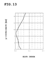
- FIG. 13 is a graph showing a relation between the blur index and the y-coordinate in example 4.
- FIG. 14 is a graph showing a relation between the spherical equivalent power and the y-coordinate in example 5.
- FIG. 15 is a graph showing a relation between the astigmatism and the y-coordinate in example 5.
- FIG. 16 is a graph showing a relation between the blur index and the y-coordinate in example 5.
- FIG. 17 is a graph showing a relation between the spherical equivalent power and the y-coordinate in comparative example 1.
- FIG. 18 is a graph showing a relation between the astigmatism and the y-coordinate in comparative example 1.
- FIG. 19 is a graph showing a relation between the blur index and the y-coordinate in comparative example 1.
- FIG. 1 is a schematic planar view of a progressive addition lens according to this embodiment.
- a progressive addition lens 1 is a spectacle lens including a distance area 2 provided in an upper part responding to a distance vision, a near area 3 provided in a lower part responding to a near vision, a progressive area 4 provided at an intermediate position in which a dioptric power is progressively changed from the distance area 2 to the near area 3 , and intermediate portions 5 provided at both sides of the progressive area 4 respectively. Note that FIG. 1 shows the progressive addition lens 1 for a right eye.
- a principal sight line 6 is provided approximately in approximately a center of the distance area 2 , the progressive area 4 and the near area 3 , which is a virtual line on a lens where a sight line is passed through when a spectacle wearer views a certain object positioned an a front lower side from a front upper side.
- the principal sight line S is also called a main meridian, composed of a distance vision line 6 A passing through the distance area 2 , a progressive line 6 B passing through the progressive area 4 , and a near vision line 6 C passing through the near area 3 .
- the distance vision line 6 A is formed along a vertical direction when wearing spectacles lens, passing through a distance vision measurement point DP which is a center of a distance vision measurement area on which a dioptric power is added in the distance area 2 .
- a progressive starting point PS is provided at a position away from the distance vision measurement point DP to some extent to a lower side.
- the progressive starting point PS coincides with an eye point.
- the eye point (fitting point) is a point as a reference for positioning when framing the spectacle lens.
- a line segment extending to the near area 3 from the progressive starting point PS including the distance vision line 6 A is set as Y-axis, and a line segment orthogonal to the Y-axis and extending in a horizontal direction is set as X-axis.
- a length of the line segment from the progressive starting point PS to the progressive end point PE, which is the length of the line segment projected to the Y-axis, is a progressive zone length.
- Original point O of the Y-axis is a prism measurement point O.
- the prism measurement point is a reference point for determining a prism action of a lens.
- the near vision line 6 C is formed along the vertical direction when, wearing spectacles, passing through the near vision measurement point NP, and is inset toward a nose side (left side in FIG. 1 ) by dimension t from the Y-axis.
- the progressive line 6 B is the line segment for connecting a lower end of the distance vision line 6 A and an upper end of the near vision line 6 C, and is formed obliquely to the distance vision line 6 A and the near vision line 6 C.
- a connection point of the near vision line 6 C and the progressive line 6 B is a progressive end point PE, and the near vision measurement point NP is provided at a position lower to some extent than the progressive end point PE.
- the distance area 2 , the near area 3 , and the progressive area 4 are formed on an inner surface (eyeball side) of the progressive addition lens 1 , and a spherical surface is formed on an outer surface (object side) of the progressive addition lens 1 .
- an aspherical design is applied to the inner surface of the progressive addition lens 1 for reducing astigmatism.
- a toric surface is set for correcting distorted vision
- a design method is for example disclosed in WO097/13382, wherein the method for designing a combined refractive surface combining the toric surface and a progressive refractive surface is disclosed for example.
- an aspherical surface addition is minutely calculated for the distance area 2 and the near area 3 , to thereby obtain an optimal aspherical surface addition. Therefore, a first reference line is set so as to extend in at least two directions of a radiating direction from a center point near a geometrical center of a lens in the distance area 2 , for example from the prism measurement point O, and a second reference line is set so as to extend in at least one direction of the radiating direction from the center point in the near area 3 , and the ashperical surface addition for a dioptric power along each reference line, is determined. Then, the aspherical surface addition for the dioptric power between these reference lines, is determined by interpolation.
- the aspherical surface addition for the dioptric power of the combined refractive surface along each reference line is determined in each reference line, under the same condition as the as-worn condition, and using a publicly-known method of calculating power, astigmatism, and prism, etc., by ray-tracing so that an optimal aspherical surface addition can be obtained.
- a horizontal line segment passing through a geometric center of the lens is defined as A-axis
- a vertical line segment is defined as B-axis
- a depth direction of the lens is defined as C-axis
- power setting in the near area 3 is performed as conventional, and meanwhile power setting in the distance area 2 is different from conventional setting.
- a method of setting a specific spherical equivalent power in the distance area 2 will be described based on an example.
- the progressive addition lens 1 with an outer surface formed into a spherical surface, an inner surface formed into a progressive surface, and having an aspheric form, is provided, in which refractive index n is 1.662, and a progressive zone length is 14 mm.
- a pantoscopic lens tilt is 6 degrees.
- an outer surface curve is 2.50 dioptre, and a thickness of a lens center is 1.1 mm.
- spherical power S is ⁇ 5.00 dioptre
- addition ADD is 2.50 dioptre
- Cylindrical power is not set in example 1.
- example 1 provides a minus lens in which the prescription value T is minus.
- FIG. 2 is a graph showing a relation between the x-coordinate indicating the as-worn spherical equivalent power D and the y-coordinate according to example 1.
- the y-coordinate of FIG. 2 corresponds to the Y-axis of FIG. 1 .
- O is the same as O of the Y-axis
- a numerical value of the y-coordinate is the same as the numerical value of the Y-axis.
- the position of 4 mm in the y-coordinate is the position on the Y-axis of the progressive starting point PS
- the position of ⁇ 10 mm in the y-coordinate is the position on the Y-axis of the progressive end point PS.
- the as-worn spherical equivalent power D in each y-coordinate is the spherical equivalent power D of the optical beam passing through the position on each Y-axis on the lens and passing through a rotation center of an eye of a wearer.
- the power deviation ⁇ D of the spherical equivalent power D from the prescription value T positioned in the distance area 2 is set to be shifted to the minus side of the prescription value T, so that the area of minus power deviation ⁇ D is included in a part of the distance area 2 .
- the spherical equivalent poser D is set so that the area in which the spherical equivalent power D is smaller than ⁇ 5.00 dioptre is included in the distance area 2 , and when the y-coordinate exceeds 8 mm, the spherical equivalent power D is shifted to the plus side of the prescription value T.
- the coordinate (x, y) is ( ⁇ 5.09 dioptre, 4 mm) at the position of the progressive starting point PS where the y-coordinate is 4 mm
- the coordinate (x, y) is ( ⁇ 5.02 dioptre, 8 mm) at the position where the y-coordinate is 8 mm
- (x, y) is ( ⁇ 4.89 dioptre, 12 mm) at the position where the y-coordinate is 12 mm.
- the power deviation ⁇ D is ⁇ 0.1 dioptre or less at maximum.
- the y-coordinate is larger than the progressive starting point PS in the distance area 2
- the spherical equivalent power D is the same value as the prescription value T
- the coordinate (x, y) of this point yc is ( ⁇ 5.00 dioptre, 8 mm).
- the position of the point yc with respect to the progressive starting point PS is 4 mm
- the position of the point yc with respect to the distance vision measurement point DP is 0 mm (the same position).
- FIG. 3 is a graph showing the relation between astigmatism and the y-coordinate.
- astigmatism in the distance area 2 is 0.11 dioptre at maximum.
- astigmatism is 0.02 dioptre when the y-coordinate is 4 mm
- astigmatism is 0.05 dioptre when the y-coordinate is 8 mm
- astigmatism is 0.10 dioptre when the y-coordinate is 12 mm.
- the blur index indicates a degree of blurring caused by the power error and the astigmatism when wearing the lens. It is difficult to objectively judge whether or not the blurring occurs, depending on magnification of a lens or sensitivity of an individual person. However, as-worn resolution, is likely to drop, as the blur index becomes larger.
- an image is formed on retina, in an appearance of not a point but a circle or an oval shape.
- a circle is called a blur circle
- an index corresponding to a length of a diagonal line of a rectangle that circumscribes the blur circle is the blur index.
- the blur index is the length (a 2 +b 2 ) 1/2 of the diagonal line of the blur circle.
- the blur index was calculated under a condition that infinite distance is viewed in an unadjusted state.
- the blur index is 0.10 when the y-coordinate is 4 mm, and the blur index is 0.04 when the y-coordinate is 8 mm, and the blur index is 0.13 when the y-coordinate is 12 mm. It is found from FIG. 4 that the blur index is smallest at a point near the point yc, and is relatively a large value at a peripheral periphery portion of the distance area 2 .
- the outer surface curve is 1.00 dioptre and the thickness of the lens center is 1.1 mm.
- spherical power is ⁇ 8.00 dioptre
- addition ADD is 2.50 dioptre.
- the cylindrical power is not set.
- FIG. 5 is the graph showing the relation between the x-coordinate showing the as-worn spherical equivalent power D, and the y-coordinate.
- the power deviation ⁇ D of the spherical equivalent power D from the prescription value T positioned in the distance area 2 is set to be shifted to the minus side of the prescription value T, so that the area of minus power deviation ⁇ D is included in a part of the distance area 2 .
- the spherical equivalent power D is set so that the minus side area where the spherical equivalent power D is shifted to the minus side from ⁇ 8.00 is included in the distance area 2 , and when the y-coordinate exceeds 9 mm, the spherical equivalent power D is shifted to the plus side of the prescription value T.
- the coordinate (x, y) is ( ⁇ 8.06 dioptre, 4 mm) at the position of the progressive starting point where the y-coordinate is 4 mm
- coordinate (x, y) is ( ⁇ 8.04 dioptre, 8 mm) at the position where the y-coordinate is 8 mm
- (x, y) is ( ⁇ 7.87 dioptre, 12 mm) at the position where the y-coordinate is 12 mm.
- the power deviation ⁇ D is ⁇ 0.1 dioptre or less at maximum.
- the y-coordinate is larger than the progressive starting point PS in the distance area 2
- the spherical equivalent power D is the same value as the prescription value T
- the coordinate (x, y) of this point yc is ( ⁇ 8.00 dioptre, 9 mm).
- the position of the point yc with respect to the progressive starting point PS is 5 mm
- the position of the point yc with respect to the distance vision measurement point DP is 1 mm.
- FIG. 6 is a graph showing the relation between the astigmatism and the y-coordinate according to example 2.
- the astigmatism in the distance area 2 is 0.11 dioptre at maximum.
- the astigmatism is 0.02 dioptre when the y-coordinate is 4 mm
- the astigmatism is 0.04 dioptre when the y-coordinate is 8 mm
- the astigmatism is 0.10 dioptre when the y-coordinate is 12 mm.
- the blue index is 0.04 when the y-coordinate is 4 mm
- the blur index is 0.03 when the y-coordinate is 8 mm
- the blur index is 0.10 when the y-coordinate is 12 mm.
- the blur index is smallest at a point near the point yc, and is relatively a large value at the peripheral periphery portion of the distance area 2 .
- the outer surface curve is 2.50 dioptre, and the thickness of the lens center is 1.1 mm.
- the prescription is as follows: Spherical power S is ⁇ 5.00 dioptre, cylindrical power C is ⁇ 2.00 dioptre, astigmatic axis is 45 degrees, and addition power ADD is 2.50 dioptre.
- FIG. 8 is a graph showing the relation between the x-coordinate showing the as-worn spherical equivalent power D and the y-coordinate according to example 3.
- the power deviation ⁇ D of the spherical equivalent power D from the prescription value T positioned in the distance area 2 is set to be shifted to the minus side of the prescription value T, so that the area of minus power deviation ⁇ D is included in a part, of the distance area 2 .
- the spherical equivalent power D is set so that the minus side area where the spherical equivalent, power D is shifted to the minus side from ⁇ 6.00 is included in the distance area 2 , and when the y-coordinate exceeds 9 mm, the spherical equivalent power D is set be the plus side of the prescription value T.
- coordinate (x, y) is ( ⁇ 6.02 dioptre, 4 mm) at the position of the progressive starting point where the y-coordinate is 4 mm
- coordinate (x, y) is ( ⁇ 6.03 dioptre, 8 mm) at the position where the y-coordinate is 8 mm
- (x, y) is ( ⁇ 5.09 dioptre, 12 mm) at the position where the y-coordinate is 12 mm.
- the power deviation ⁇ D is ⁇ 0.08 dioptre or less at maximum.
- the y-coordinate is larger than the progressive starting point PS in the distance area 2
- the spherical equivalent power D is the same value as the prescription value T
- the coordinate (x, y) of this point yc is ( ⁇ 6.00 dioptre, 9 mm).
- the position of the point yc with respect to the progressive starting point PS is 5 mm
- the position of the point yc with respect to the distance vision measurement point DP is 1 mm.
- FIG. 9 is the graph showing the relation between the astigmatism and the y-coordinate according to example 3.
- the astigmatism in the distance area 2 is 0.32 dioptre at maximum. Astigmatism is 0.02 dioptre when the y-coordinate is 4 mm, and astigmatism is 0.13 dioptre when the y-coordinate is 8 m, and astigmatism is 0.24 dioptre when the y-coordinate is 12 mm.
- the blur index is 0.02 when the y-coordinate is 4 mm, and the blue index is 0.03 when the y-coordinate is 8 mm, and the blur index is 0.10 when the y-coordinate is 12 mm. It is found that the blur index is smallest at a point near the point yc, and is relatively a large value at the peripheral periphery portion of the distance area 2 .
- the outer surface curve is 7.00 dioptre, and the thickness of the lens center is 4.1 mm.
- the prescription is as follows: the spherical power S is +4.50 dioptre, and the addition ADD is 1.50 dioptre. In example 4, the cylindrical power is not set.
- FIG. 11 is a graph showing the relation between the x-coordinate showing the as-worn spherical equivalent power D and the y-coordinate according to example 4.
- the power deviation ⁇ D of the spherical equivalent power D from the prescription value T positioned in the distance area 2 is set to be shifted to the plus side of the prescription value T, so that the area of plus power deviation ⁇ D is included in a part of the distance area 2 .
- the spherical equivalent power D is set so that the area in which the spherical equivalent power D is shifted to the plus side from +4.5 is included in the distance area 2 , and when the y-coordinate exceeds 9 mm, the spherical equivalent power D is shifted to the minus side of the prescription value T.
- the coordinate (x, y) is (4.56 dioptre, 4 mm) at the position of the progressive starting point where the y-coordinate is 4 mm
- the coordinate (x, y) is (4.51 dioptre, 8 mm) at the position where the y-coordinate is 8 mm
- (x, y) is (4.43 dioptre, 12 mm) at the position where the y-coordinate is 12 mm.
- the power deviation OD is ⁇ 0.06 dioptre or less at maximum.
- the y-coordinate is larger than the progressive starting point PS in the distance area 2
- the spherical equivalent power D is the same value as the prescription value T
- the coordinate (x, y) of this point yc is (4.5 dioptre, 9 mm).
- the position of the point yc with respect to the progressive starting point PS is 5 mm
- the position of the point yc with respect to the distance vision measurement point DP is 1 mm.
- FIG. 12 is a graph showing the relation between the astigmatism and the y-coordinate according to example 4.
- the astigmatism in the distance area 2 is 0.06 dioptre at maximum.
- the astigmatism is 0.02 dioptre when the y-coordinate is 4 mm
- the astigmatism is 0.02 dioptre when the y-coordinate is 8 mm
- the astigmatism is 0.00 dioptre when the y-coordinate is 12 mm.
- the blur index is 0.08 when the y-coordinate is 4 mm, and the blur index is 0.02 when the y-coordinate is 8 mm, and the blur index is 0.08 when the y-coordinate is 12 mm. It is found that the blur index is smallest at a point near the point yc, and is relatively a large value at the peripheral periphery portion of the distance area 2 .
- the outer surface curve is 5.00 dioptre, and the thickness of the lens center is 3.3 mm.
- the prescription is as follows: Spherical power S is +3.00 dioptre, the addition ADD is 1.50 dioptre. In example 5, the cylindrical power is not set.
- FIG. 14 is a graph showing the relation between the x-coordinate showing the as-worn spherical equivalent power D and the y-coordinate.
- the power deviation ⁇ D of the spherical equivalent power D from the prescription value T positioned in the distance area 2 is set to be shifted to the plus side of the prescription value T, so that the area of plus power deviation ⁇ D is included in a part of the distance area.
- the spherical equivalent power D is set so that the plus side area where the spherical equivalent power D is shifted to the plus side from +3.0 is included in the distance area 2 , and when the y-coordinate exceeds 7 mm, the spherical equivalent power D is shifted to the minus side of the prescription value T.
- the coordinate (x, y) is (3.08 dioptre, 4 mm) at the position of the progressive starting point PS where the y-coordinate is 4 mm
- the coordinate (x, y) is (2.99 dioptre, 8 mm) at the position where the y-coordinate is 8 mm
- (x, y) is (2.92 dioptre, 12 mm) at the position where the y-coordinate is 12 mm.
- the power deviation ⁇ D is 0.08 dioptre or less at maximum.
- the y-coordinate is larger than the progressive starting point PS in the distance area 2
- the spherical equivalent power D is the same value as the prescription value T
- the coordinate (x, y) of this point yc is (3.0 dioptre, 7 mm).
- the position of the point yc with respect to the progressive starting point PS is 3 mm
- the position of the point yc with respect to the distance vision measurement point DP is ⁇ 1 mm.
- FIG. 15 is a graph showing the relation between the astigmatism and the coordinate y according to example 5.
- the astigmatism in the distance area 2 is 0.05 dioptre at maximum.
- the astigmatism is 0.03 dioptre when the y-coordinate is 4 mm
- the astigmatism is 0.02 dioptre when the y-coordinate is 8 mm
- the astigmatism is 0.00 dioptre when the y-coordinate is 12 mm.
- the blur index is 0.15 when the y-coordinate is 4 mm, and the blur index is 0.03 when the y-coordinate is 8 mm, and the blur index is 0.14 when the y-coordinate is 12 mm. It is found that the blur index is smallest at a point near the point yc, and is relatively a large value at the peripheral periphery portion of the distance area 2 .
- Comparative example 1 provides a conventional progressive addition lens and is the same as example 1 excluding a point that the power deviation ⁇ D is not set.
- a progressive addition lens 1 formed into an outer spherical surface, inner progressive and aspheric form, in which a refractive index n is 1.662, and a progressive zone length is 14 mm.
- the as-worn pantoscopic angle is 6 degrees.
- the outer surface curve is 2.50 dioptre, and the thickness of the lens center is 1.1 mm.
- the prescription is as follows: the spherical power S is ⁇ 5.00 dioptre, and the addition ADD is 2.50 dioptre. In comparative example 1, the cylindrical power is not set.
- comparative example 1 provides a minus lens in which the prescription value T is minus.
- FIG. 17 is a graph of the relation between the x-coordinate showing the as-worn spherical equivalent power D and the y-coordinate according to comparative example 1.
- the spherical equivalent power D at the progressive starting point PS is ⁇ 4.94 dioptre when the y-coordinate is 4 mm, and the spherical equivalent power D is ⁇ 4.95 dioptre when the y-coordinate is 8 mm, and the spherical equivalent power D is ⁇ 4.84 when the y-coordinate is 12 mm.
- FIG. 18 is a graph showing the relation between the astigmatism and the y-coordinate according to comparative example 1.
- the astigmatism in the distance area 2 is 0.07 dioptre at maximum.
- the astigmatism is 0.02 dioptre when the y-coordinate is 4 mm
- the astigmatism is 0.03 dioptre when the y-coordinate is 8 mm
- the astigmatism is 0.06 dioptre when the y-coordinate is 12 mm.
- the blur index is 0.07 when the y-coordinate is 4 mm, and the blur index is 0.06 when the y-coordinate is 8 mm, and the blur index is 0.19 when the y-coordinate is 12 mm.
- example 1 When example 1 and comparative example 1 are compared, in example 1, the area of minus power deviation ⁇ D where the as-worn spherical equivalent power D is minus from the prescription value T, is included in the distance area 2 , and meanwhile in comparative example 1, the area of minus power deviation ⁇ D does not exist.
- Example 1 and comparative example 1 are different from each other in this point, but other conditions are same.
- the blur index of example 1 is higher at the point near the progressive starting point PS compared with comparative example 1.
- the blur index is low in most of the area of the distance area 2 .
- the value 0.10 is not a heavy burden on a lens wearer.
- the blur index is 0.10 or more in an area where the y-coordinate is 9 mm or more, and when the y-coordinate exceeds 12 mm in the peripheral part of the distance area 2 , the blur index is 0.20 or more, and a heavy burden is added on the lens wearer.
- the prescription value T is minus, which is obtained from the formula “S+C/2” expressed by the prescribed spherical power S and the cylindrical power C in the progressive addition lens including the distance area 2 , the near area 3 , and the progressive area 4 , with the inner surface formed into the aspheric form, the area of minus power deviation ⁇ D where the power deviation ⁇ D of the spherical equivalent power D from the prescription value T is minus, is on the principal sight line 6 in the distance area 2 .
- the power error between the spherical equivalent power D and the prescription value T in the periphery of the distance area 2 is smaller than a conventional power error.
- the prescription value T is plus
- the area of plus power deviation ⁇ D of the spherical equivalent power D from the prescription value T is in the distance area 2 . Therefore, even if the spherical equivalent power D is shifted to the minus side toward the periphery, the deviation of the spherical equivalent power D from the prescription value T is smaller than conventional in the periphery of the distance area.
- the astigmatism in the peripheral part of the distance area 2 is reduced by designing the aspherical surface, and by shift of the power of the whole distance area 2 , the power error in the periphery of the distance area 2 can be reduced.
- the progressive addition lens can be manufactured in the same way as conventional. Namely, the conventional method can be utilized, because the range of the power deviation ⁇ D is matched with the power difference of the conventional progressive addition lens in which the prescription for the spherical power S and the cylindrical power G is sorted at 0.25 dioptre pitch. Even if the value close to the prescription value T is obtained at the distance vision measurement point DP, power shift of 0.25 dioptre pitch or more occurs at the progressive starting point PS which is only several millimeters away from the distance vision measurement point DP, and therefore not the prescribed lens but the neighboring lens is fabricated against a request of a prescription side. Such a situation is not preferable.
- Framing of the progressive addition lens 1 is preferably performed in such a manner that the circle having a diameter of 8 mm is fitted into a frame.
- point yc exists at a position of ⁇ 4 mm (at a position of 1 mm in examples 1 to 4, and at a position of ⁇ 1 mm in example 5) from the position of the distance vision measurement point DP. Therefore, the spectacle having the progressive addition lens of this embodiment can be easily manufactured by a general framing method. Namely, the spectacle having the effect of this embodiment can be provided.
- Both of the aspherical surface and the progressive surface are formed on the inner surface, and the spherical surface is formed on the outer surface, and therefore by fixing the outer surface curve, a generation factor of swing or distortion is reduced, and therefore an optical performance can be improved.
- the present invention is not limited to the abovementioned embodiment, and includes a modification shown below in a range of achieving the object of the present invention.
- the lens is configured to have both of the progressive surface and the aspherical surface design which is combined with the progressive surface (including a toric surface for correcting astigmatism) formed on the inner surface.
- the aspherical surface design (including the toric surface) may be formed on both of the inner surface and the outer surface or only on the outer surface
- the progressive surface may be formed on both of the inner surface and the outer surface or only on the outer surface.
- both of the inner surface and the outer surface may be formed into aspherical surface shapes, and by combining them, the function of the progressive addition lens can be obtained when wearing spectacles.
Applications Claiming Priority (3)
| Application Number | Priority Date | Filing Date | Title |
|---|---|---|---|
| JP2011215048A JP5989317B2 (ja) | 2011-09-29 | 2011-09-29 | 累進屈折力レンズ、その製造方法、およびその設計方法 |
| JP2011-215048 | 2011-09-29 | ||
| PCT/JP2012/006167 WO2013046677A1 (fr) | 2011-09-29 | 2012-09-27 | Lentille à réfringence progressive |
Publications (2)
| Publication Number | Publication Date |
|---|---|
| US20140240662A1 US20140240662A1 (en) | 2014-08-28 |
| US9429770B2 true US9429770B2 (en) | 2016-08-30 |
Family
ID=47994754
Family Applications (1)
| Application Number | Title | Priority Date | Filing Date |
|---|---|---|---|
| US14/348,796 Active US9429770B2 (en) | 2011-09-29 | 2012-09-27 | Progressive addition lens |
Country Status (5)
| Country | Link |
|---|---|
| US (1) | US9429770B2 (fr) |
| EP (1) | EP2762952B1 (fr) |
| JP (1) | JP5989317B2 (fr) |
| CN (1) | CN103842891B (fr) |
| WO (1) | WO2013046677A1 (fr) |
Families Citing this family (4)
| Publication number | Priority date | Publication date | Assignee | Title |
|---|---|---|---|---|
| JP2015194511A (ja) * | 2014-03-31 | 2015-11-05 | ホヤ レンズ タイランド リミテッドHOYA Lens Thailand Ltd | 眼鏡レンズを製造するための装置、方法及びプログラム並びに眼鏡レンズの製造方法及びレンズ供給システム |
| JP2020106644A (ja) * | 2018-12-27 | 2020-07-09 | 株式会社ニコン・エシロール | 累進屈折力眼鏡レンズ |
| JP7466137B2 (ja) * | 2019-09-26 | 2024-04-12 | 学校法人北里研究所 | サーバ装置、発注システム、情報提供方法、およびプログラム |
| TWI741902B (zh) * | 2020-12-07 | 2021-10-01 | 春秋光學股份有限公司 | 用於減緩或預防近視進展之鏡片 |
Citations (12)
| Publication number | Priority date | Publication date | Assignee | Title |
|---|---|---|---|---|
| JPH08114775A (ja) | 1994-08-26 | 1996-05-07 | Tokai Kogaku Kk | 老視矯正用レンズ |
| US5719657A (en) | 1993-11-19 | 1998-02-17 | Asahi Kogaku Kogyo Kabushiki Kaisha | Progressive power lens |
| US5777716A (en) | 1994-08-26 | 1998-07-07 | Tokai Kogaku Kabushiki Kaisha | Progressive power presbyopia-correcting ophthalmic lenses |
| US5892565A (en) | 1996-10-18 | 1999-04-06 | Nikon Corporation | Progressive multifocal lens |
| US6186627B1 (en) | 1998-12-03 | 2001-02-13 | Asahi Kogaku Kabushiki Kaisha | Back-surface progressive power lens |
| US6318859B1 (en) | 1996-09-20 | 2001-11-20 | Essilor International | Set of progressive multifocal ophthalmic lenses |
| US20040257527A1 (en) * | 2002-10-08 | 2004-12-23 | Hua Qi | Method for determining optical value of lens of eyeglasses, process for producing lens of eyeglasses, lens of eyeglasses and its ordering/ordr receiving system |
| US20060176446A1 (en) | 2005-02-04 | 2006-08-10 | Seiko Epson Corporation | Method of designing a spectacle lens |
| US7125118B2 (en) * | 2003-04-02 | 2006-10-24 | Seiko Epson Corporation | Progressive multifocal lens and method of designing the same |
| JP2007504485A (ja) | 2003-08-29 | 2007-03-01 | ローデンストック.ゲゼルシャフト.ミット.ベシュレンクテル.ハフツング | エラー対策を施したプログレッシブガラスの設計 |
| JP2009244600A (ja) | 2008-03-31 | 2009-10-22 | Tokai Kogaku Kk | 累進屈折力レンズおよびその製造方法 |
| US20120203368A1 (en) * | 2011-02-08 | 2012-08-09 | Rodenstock Gmbh | Method and system for optimizing a spectacle lens based on individual parameters of a wearer |
Family Cites Families (4)
| Publication number | Priority date | Publication date | Assignee | Title |
|---|---|---|---|---|
| JP3495437B2 (ja) * | 1993-11-19 | 2004-02-09 | ペンタックス株式会社 | 累進多焦点レンズ |
| JP3852116B2 (ja) | 1995-11-24 | 2006-11-29 | セイコーエプソン株式会社 | 累進多焦点レンズ及び眼鏡レンズ |
| DE60043537D1 (de) * | 1999-04-13 | 2010-01-28 | Hoya Corp | Glaslinse mit progressiver brechkraft und entwurfsverfahren dafür |
| JP2011203705A (ja) * | 2010-03-01 | 2011-10-13 | Seiko Epson Corp | 眼鏡レンズ及びその設計方法 |
-
2011
- 2011-09-29 JP JP2011215048A patent/JP5989317B2/ja active Active
-
2012
- 2012-09-27 US US14/348,796 patent/US9429770B2/en active Active
- 2012-09-27 WO PCT/JP2012/006167 patent/WO2013046677A1/fr active Application Filing
- 2012-09-27 CN CN201280042947.8A patent/CN103842891B/zh active Active
- 2012-09-27 EP EP12837281.0A patent/EP2762952B1/fr active Active
Patent Citations (14)
| Publication number | Priority date | Publication date | Assignee | Title |
|---|---|---|---|---|
| US5719657A (en) | 1993-11-19 | 1998-02-17 | Asahi Kogaku Kogyo Kabushiki Kaisha | Progressive power lens |
| JPH08114775A (ja) | 1994-08-26 | 1996-05-07 | Tokai Kogaku Kk | 老視矯正用レンズ |
| US5777716A (en) | 1994-08-26 | 1998-07-07 | Tokai Kogaku Kabushiki Kaisha | Progressive power presbyopia-correcting ophthalmic lenses |
| US6318859B1 (en) | 1996-09-20 | 2001-11-20 | Essilor International | Set of progressive multifocal ophthalmic lenses |
| US5892565A (en) | 1996-10-18 | 1999-04-06 | Nikon Corporation | Progressive multifocal lens |
| US6186627B1 (en) | 1998-12-03 | 2001-02-13 | Asahi Kogaku Kabushiki Kaisha | Back-surface progressive power lens |
| US20040257527A1 (en) * | 2002-10-08 | 2004-12-23 | Hua Qi | Method for determining optical value of lens of eyeglasses, process for producing lens of eyeglasses, lens of eyeglasses and its ordering/ordr receiving system |
| US7125118B2 (en) * | 2003-04-02 | 2006-10-24 | Seiko Epson Corporation | Progressive multifocal lens and method of designing the same |
| JP2007504485A (ja) | 2003-08-29 | 2007-03-01 | ローデンストック.ゲゼルシャフト.ミット.ベシュレンクテル.ハフツング | エラー対策を施したプログレッシブガラスの設計 |
| US20070109496A1 (en) | 2003-08-29 | 2007-05-17 | Rodenstock Gmbh | Error-tolerant progressive glas design |
| US20060176446A1 (en) | 2005-02-04 | 2006-08-10 | Seiko Epson Corporation | Method of designing a spectacle lens |
| JP4192899B2 (ja) | 2005-02-04 | 2008-12-10 | セイコーエプソン株式会社 | 眼鏡レンズの設計方法 |
| JP2009244600A (ja) | 2008-03-31 | 2009-10-22 | Tokai Kogaku Kk | 累進屈折力レンズおよびその製造方法 |
| US20120203368A1 (en) * | 2011-02-08 | 2012-08-09 | Rodenstock Gmbh | Method and system for optimizing a spectacle lens based on individual parameters of a wearer |
Non-Patent Citations (3)
| Title |
|---|
| International Search Report issued in International Patent Application No. PCT/JP2012/006167 mailed Jan. 15, 2013. |
| Jun. 5, 2015 Extended Search Report issued in European Application No. 12837281.0. |
| Written Opinion of the International Searching Authority issued in International Patent Application No. PCT/JP2012/006167 mailed Jan. 15, 2013. |
Also Published As
| Publication number | Publication date |
|---|---|
| WO2013046677A1 (fr) | 2013-04-04 |
| CN103842891A (zh) | 2014-06-04 |
| US20140240662A1 (en) | 2014-08-28 |
| EP2762952B1 (fr) | 2021-03-03 |
| JP2013076740A (ja) | 2013-04-25 |
| CN103842891B (zh) | 2016-03-23 |
| EP2762952A1 (fr) | 2014-08-06 |
| EP2762952A4 (fr) | 2015-07-08 |
| JP5989317B2 (ja) | 2016-09-07 |
Similar Documents
| Publication | Publication Date | Title |
|---|---|---|
| US7527376B2 (en) | Method for designing spectacle lens, spectacle lens, and spectacles | |
| KR101902372B1 (ko) | 누진 안경 렌즈 | |
| US8162478B2 (en) | Pair of progressive power lens and method for designing same | |
| KR101281459B1 (ko) | 안과용 렌즈를 결정하는 방법 | |
| JP2009517709A (ja) | 眼鏡レンズ | |
| EP3362842B1 (fr) | Procédé permettant de fabriquer une lentille à addition progressive ophtalmique et pour un porteur emmétrope et presbyte | |
| JP2010513967A (ja) | 眼鏡レンズを決定する方法 | |
| KR20140057196A (ko) | 누진 안경 렌즈 결정 방법 | |
| US10036898B2 (en) | Method for determining an ophthalmic lens comprising an aspherical continuous layer on one of its faces and an aspherical Fresnel layer on one of its faces | |
| US9429770B2 (en) | Progressive addition lens | |
| JP6226873B2 (ja) | 眼用累進レンズ及び半仕上げレンズブランクの組を決定する方法 | |
| US20140362340A1 (en) | Non-progressive corridor bi-focal lens with substantially tangent boundary of near and distant visual fields | |
| US11892711B2 (en) | Method for determining a single vision ophthalmic lens | |
| CN112882253B (zh) | 渐进屈光力镜片对的设计方法及制造方法 | |
| US8757799B2 (en) | Progressive multifocal ophthalmic lens | |
| JP5040889B2 (ja) | 眼鏡レンズの設計方法 | |
| JP7055097B2 (ja) | 正視で老眼の装用者のための累進屈折力レンズと、かかるレンズを提供する方法 | |
| US10656439B2 (en) | Lenses with improved management of distortion | |
| US11681163B2 (en) | Pair of progressive power lenses and design method for the same | |
| KR100705120B1 (ko) | 누진 굴절력 렌즈 및 제조 방법 | |
| EP3722865A1 (fr) | Procédés et systèmes pour optimiser une fonction optique d'une lentille ophtalmique progressive dans des conditions de port spécifiques | |
| JP2015158688A (ja) | 内面累進屈折力レンズ、内面累進屈折力レンズの設計方法、及び内面累進屈折力レンズの製造方法 | |
| JP2012083481A (ja) | 累進屈折力レンズ | |
| JP2013130619A (ja) | 眼鏡レンズ |
Legal Events
| Date | Code | Title | Description |
|---|---|---|---|
| AS | Assignment |
Owner name: HOYA LENS MANUFACTURING PHILIPPINES INC., PHILIPPI Free format text: ASSIGNMENT OF ASSIGNORS INTEREST;ASSIGNOR:SUZUKI, YOHEI;REEL/FRAME:032803/0797 Effective date: 20140413 |
|
| AS | Assignment |
Owner name: EHS LENS PHILIPPINES, INC., PHILIPPINES Free format text: CHANGE OF NAME;ASSIGNOR:HOYA LENS MANUFACTURING PHILIPPINES INC.;REEL/FRAME:035801/0452 Effective date: 20150401 |
|
| STCF | Information on status: patent grant |
Free format text: PATENTED CASE |
|
| MAFP | Maintenance fee payment |
Free format text: PAYMENT OF MAINTENANCE FEE, 4TH YEAR, LARGE ENTITY (ORIGINAL EVENT CODE: M1551); ENTITY STATUS OF PATENT OWNER: LARGE ENTITY Year of fee payment: 4 |
|
| MAFP | Maintenance fee payment |
Free format text: PAYMENT OF MAINTENANCE FEE, 8TH YEAR, LARGE ENTITY (ORIGINAL EVENT CODE: M1552); ENTITY STATUS OF PATENT OWNER: LARGE ENTITY Year of fee payment: 8 |