US9429348B2 - Method and device for producing snow - Google Patents
Method and device for producing snow Download PDFInfo
- Publication number
- US9429348B2 US9429348B2 US13/394,861 US201013394861A US9429348B2 US 9429348 B2 US9429348 B2 US 9429348B2 US 201013394861 A US201013394861 A US 201013394861A US 9429348 B2 US9429348 B2 US 9429348B2
- Authority
- US
- United States
- Prior art keywords
- air
- snowflakes
- flow
- supply line
- cold air
- Prior art date
- Legal status (The legal status is an assumption and is not a legal conclusion. Google has not performed a legal analysis and makes no representation as to the accuracy of the status listed.)
- Expired - Fee Related, expires
Links
Images


Classifications
-
- F—MECHANICAL ENGINEERING; LIGHTING; HEATING; WEAPONS; BLASTING
- F25—REFRIGERATION OR COOLING; COMBINED HEATING AND REFRIGERATION SYSTEMS; HEAT PUMP SYSTEMS; MANUFACTURE OR STORAGE OF ICE; LIQUEFACTION SOLIDIFICATION OF GASES
- F25C—PRODUCING, WORKING OR HANDLING ICE
- F25C3/00—Processes or apparatus specially adapted for producing ice or snow for winter sports or similar recreational purposes, e.g. for sporting installations; Producing artificial snow
- F25C3/04—Processes or apparatus specially adapted for producing ice or snow for winter sports or similar recreational purposes, e.g. for sporting installations; Producing artificial snow for sledging or ski trails; Producing artificial snow
-
- F—MECHANICAL ENGINEERING; LIGHTING; HEATING; WEAPONS; BLASTING
- F25—REFRIGERATION OR COOLING; COMBINED HEATING AND REFRIGERATION SYSTEMS; HEAT PUMP SYSTEMS; MANUFACTURE OR STORAGE OF ICE; LIQUEFACTION SOLIDIFICATION OF GASES
- F25C—PRODUCING, WORKING OR HANDLING ICE
- F25C3/00—Processes or apparatus specially adapted for producing ice or snow for winter sports or similar recreational purposes, e.g. for sporting installations; Producing artificial snow
-
- F—MECHANICAL ENGINEERING; LIGHTING; HEATING; WEAPONS; BLASTING
- F25—REFRIGERATION OR COOLING; COMBINED HEATING AND REFRIGERATION SYSTEMS; HEAT PUMP SYSTEMS; MANUFACTURE OR STORAGE OF ICE; LIQUEFACTION SOLIDIFICATION OF GASES
- F25C—PRODUCING, WORKING OR HANDLING ICE
- F25C2303/00—Special arrangements or features for producing ice or snow for winter sports or similar recreational purposes, e.g. for sporting installations; Special arrangements or features for producing artificial snow
- F25C2303/044—Snow making using additional features, e.g. additives, liquid gas
Definitions
- the present invention relates to a method and a device for producing snow from flows of humid air and cold air.
- snow cannons which are widely used in ski resorts, do not produce snow as such, but only specific types of snow, mainly corresponding to fully or partly frozen water droplets (being called “sleet” or “graupel” when occurring in nature).
- snowflakes gradually grow in the course of the re-sublimation (i.e., the phase transition from vapor phase to solid phase), and only nuclei required for the initiation of ice crystal growth can be formed by freezing.
- European Patent Application Publication EP 1,710,519 A1 Nilsson in European Patent Application Publication EP 1,710,519 A1, for example, while European Patent Application Publication EP 1,065,456 A1 describes a snow cannon which is operated within a closed space, such as in a tent, in order to make it possible to influence the characteristics of the flow of cold air.
- U.S. Pat. No. 3,257,815 describes a device for producing snow from atomized water and cold air, wherein the water mist which is falling down is frozen by contacting cold air rising from the bottom; the artificial snow is then released at the bottom end of the device.
- Japanese patent application publication JP 46-7151 A also describes a method for producing snow using water mist and cold air.
- sleet and ice crystals are produced in the first of two freezing chambers which are kept at a temperature of ⁇ 35 to ⁇ 30° C.
- the sleet mixture is kept floating for several minutes in both chambers by a flow of cold air, which is blown in from the bottom, and is converted into “snow” in the second chamber.
- the thus obtained snow is moved to a third chamber, which is kept at a temperature of ⁇ 15 to ⁇ 20° C. by blowing down cold air onto the snow from above, in order to prevent the snow from being reconverted into ice, where it is stored.
- the sleet i.e. ice grains
- the sleet i.e. ice grains
- the formation of the above described “fluffy” or dendritic snow is not possible in this case either, because this type of snow is only produced from an atmosphere oversaturated with vapor. It is not possible to create such an atmosphere by the method according to JP 46-7151 A in the first place: because of the low temperature ( ⁇ 35 to ⁇ 30° C.) in the first freezing chamber, the water droplets spontaneously freeze into ice droplets and sleet.
- the humidity in each chamber will correspond to the respective temperature therein, but it will not be possible to achieve an oversaturation of the atmosphere, especially because the atmosphere is not further cooled in the subsequent chambers, but also additional non-humidified “dry” air is supplied and, in the third chamber, significantly warmer air is used.
- European Patent Application Publication EP 609,140 A1 discloses the production of snow within a closed tunnel in which the snow circulates and which may therefore be used as a snow channel for testing various materials and articles under the influence of snow fall. Except for its moisture content, the characteristics of the thus obtained snow are not described, and the device described therein is not suited for the production of snow for ski slopes either.
- the present invention reaches this aim by providing a method for producing substantially dendritic snow, the method comprising the following steps:
- the method of the invention makes it possible to simulate the conditions snowflakes are subjected to in nature and to produce snow which is as nature-identical as possible. Additionally, compared to the operation of traditional snow cannons, the present invention significantly reduces the amount of energy required for producing a certain amount of snow, and the emission of noise is practically entirely eliminated.
- the distance covered by the crystals within the substantially closed space is many times greater than the distance covered when using an uncontrolled air current, which allows for a significantly increased residence time.
- the predetermined period of time in step b) preferably amounts to at least about 5 min, more preferably to at least 10 min or at least 15 min.
- the predefined size in step b) preferably is in the order of dendritic snowflakes.
- the method of the invention preferably produces snow having a density of less than 200 kg/m 3 , which is perfectly suited as a material for artificial snow covers for ski slopes.
- step b) means that the snowflakes and ice crystals, which are whirled up and transported by the combined air flow and which, of course, are not all transported on an imaginary helical trajectory, move through the substantially closed space in such a way that the mass flow resulting from the individual movements of the snowflakes follows a substantially helical trajectory. Whether this mass movement closely corresponds to a helical form or not, of course, also depends on the sectional shape of the substantially closed space. It is clear that the movement comes closest to the helical form in the case of circular sections.
- the snowflakes' weight increases when they grow, but, at the same time, their specific surface area gets larger, so that they are more easily transported and carried away by the air. For this reason, while they are floating and moving along the substantially helical trajectory within the substantially closed space, the growing snowflakes are distributed in a way that, in the case of an upward helical movement, larger flakes are found at greater heights, while smaller flakes and ice crystal nuclei are found at lower heights. In the topmost area of the substantially closed space, the snowflakes have substantially reached the size and shape of nature-identical dendritic snowflakes.
- one or more additives for supporting the formation/growth of crystals in step b) are preferably supplied together with the flow of humid air and/or with the flow of cold air, whereby these two processes can be significantly accelerated, which increases the cost effectiveness of the method.
- ice crystal nuclei are supplied as additives together with the flow of humid air and/or with the flow of cold air in order to initiate the formation of ice crystals and/or to promote the growth of ice crystals.
- one or more foaming agents for producing air bubbles, on the surface of which the formation of ice crystals is initiated may be supplied. In this way, the amount of snow produced per time unit, i.e., the density of the snowflakes in the atmosphere of the substantially closed space, can be increased.
- step b) The way in which the ice crystals and snowflakes are kept floating and their movement on the substantially helical trajectory is achieved in step b) is not subject to any particular limitations.
- at least one of the two flows of humid and cold air is fed into the substantially closed space from below at an oblique angle.
- at least one of the two flows of humid and cold air is laterally supplied to the substantially closed space.
- At least one of the flows of humid and cold air in step a) is fed in a substantially tangential direction into a substantially closed space that is conical, which makes it easier to obtain a rotational movement and, at the same time, initiates an upward movement, which results in the desired helical trajectory.
- a combination of lateral and bottom air flow supplies i.e., supplying at least one air flow from below at an oblique angle and at least one air flow laterally, especially in a tangential direction into a conical space, is particularly preferred in order to create a stable upward rotational movement and to be in the position to control this movement by an adequate adaptation of the volume flows.
- the residence time of the snowflakes produced by the method of the invention and the thus obtainable size of the same can be controlled.
- the growing snowflakes in step b) may also be transported along the substantially helical trajectory by one or more fans provided in the substantially closed space.
- Such fans preferably only support the air movements created by the way in which the air flows are supplied into the space, or, considering the additional energy they would require, are not provided at all.
- the temperature of the flow of cold air in step a) is only subject to the limitation that it has to be below 0° C.
- the temperature is in the range of ⁇ 100° C. to ⁇ 5° C., more preferably in the range of ⁇ 20° C. to ⁇ 5° C.
- the cold air may be pre-cooled in order to obtain the desired temperature, or it may simply be ambient air that is supplied as the flow of cold air, if it has the required temperature below the freezing point. Of course, the latter way is preferred due to the lower consumption of energy.
- the temperature of the flow of humid air in step a) is not subject to any particular limitations.
- a compromise is struck between a higher temperature at which the degree of the air's saturation with water is higher and a lower temperature at which the amount of cold air required for obtaining a temperature below 0° C. within the substantially closed space is lower.
- the temperature of the flow of humid air thus, preferably is in the range of ⁇ 5° C. to +10° C.
- An embodiment of the invention in which the ambient air is separately moistened and supplied into the substantially closed space as the flow of humid air is preferred.
- the supplied humid air is preferably warmed before or while moisture is added thereto in order to raise the water saturation point.
- This way of supplying water is not subject to any particular limitations.
- the water is absorbed when an air flow is blown over an open water container and/or through a water container. In both cases, the water container may be heated.
- the surface of the substantially closed space is at least partially cooled and/or heated in order to specifically prevent or promote the condensation of water in certain areas of the surface.
- the top area of a conical space, in which mainly larger snowflakes are to be found, may, for example, be cooled in order to prevent these larger flakes from condensing.
- the energy used for heating the surface of the substantially closed space, the flow of humid air, or the water container preferably is the waste heat resulting from a cooling process carried out as part of the method, e.g. from the above-mentioned cooling of the surface or from the additional cooling of the cold air. In this way, the energy required for carrying out the method can be further reduced.
- step c) of the method the snowflakes are preferably released from the substantially closed space together with the carrier air flow through a nozzle in order to accelerate the snowflakes to the required speed, so that it is possible to cover the area around the production site with the snow produced by the method of the invention.
- the snowflakes are released through a Venturi nozzle which is operated using a flow of ambient air, by which a negative pressure is created in the top area of the substantially closed space, the negative pressure sucking the snowflakes present in the top area, i.e. snowflakes of the predefined size, into the nozzle.
- step c) the snowflakes can also be released into a storage container in order to store them for any later application, e.g. for covering ski slopes with snow or for the preservation of food.
- sterilized water for the generation of the flow of humid air.
- the present invention provides a device for producing substantially dendritic snow by carrying out the method of the first aspect, the device comprising at least one substantially closed chamber which in turn comprises:
- a mixing zone into which at least one supply line for humid air and at least one supply line for cold air lead, for mixing the flows of humid and cold air and, optionally, for forming ice crystal nuclei; a growth zone for snowflakes; and a release zone where the produced snowflakes are released;
- this “division” does not necessarily refer to a spatial separation and that a “zone” does not necessarily constitute a spatially separated area.
- a “zone” may thus also only refer to an area of the space within a chamber in which mainly one of the processes being part of the inventive method, i.e. the mixing of the air flows, the growing of snowflakes, and the release of the snowflakes via the release opening, is taking place. This means that all three zones may also be provided within a single, substantially closed chamber, without being clearly delineated, i.e. without any physical boundaries.
- a separate substantially closed chamber for each of the three zones may be provided.
- the device may comprise several substantially closed chambers which may be connected in series or in parallel, each of the chambers comprising either all three zones or only one or two of the zones. If one chamber comprises more than one zone, different built-in fittings may be provided for partially separating the zones. However, it is preferred that all three processes are carried out within one single chamber.
- the types(s) and shape(s) of the chamber(s) is (are) not subject to any particular limitations.
- the flows of humid and cold air may also be introduced into a single tubular chamber which is helically wound upwards or downwards, which makes the combined air flow, on average, follow the desired helical trajectory.
- a tubular chamber would be required to be very long in order to produce substantially dendritic snowflakes, such embodiments are not preferred, while chambers having a significantly lower aspect ratio between length and height, e.g. an aspect ratio ⁇ 10:1, are preferred.
- the means for moving the ice crystal nuclei and snowflakes along a substantially helical trajectory are not subject to any particular limitations, so that it is possible to use any air flow control means such as fans, various fittings, e.g. deflector plates, ridges, and grooves in the inner surface of the chamber(s).
- any air flow control means such as fans, various fittings, e.g. deflector plates, ridges, and grooves in the inner surface of the chamber(s).
- at least one air supply line and/or at least one air flow control means preferably a fan, as such means.
- the substantially closed chamber or, if the device comprises more than one chamber, one or more substantially closed chambers preferably is/are conical at least in the area of the release zone in order to create a stable, substantially helical air movement towards the release opening.
- such chambers may also be conical in the areas of the growth zone and the release zone in order to provide a stable, substantially helical movement in these areas so as to allow for a more precise control of the residence time of the snowflakes in the individual zones.
- a chamber preferably is entirely conical.
- At least one supply line for humid air and/or at least one supply line for cold air enter(s) the mixing zone from below at an oblique angle in order to cause the substantially helical movement of the air within the chamber and thus to serve as the means for moving the ice crystal nuclei and snowflakes along a substantially helical trajectory.
- at least one supply line for humid air and/or at least one supply line for cold air laterally enter(s) the mixing zone and/or the growth zone.
- At least one supply line for humid air and/or at least one supply line for cold air enter(s) a conical mixing zone and/or growth zone in a substantially tangential direction, which provides for a substantially helical trajectory with a low pitch and thus for an extended residence time of the snowflakes within the chamber.
- the height of the chamber required for obtaining substantially dendritic snowflakes may be reduced by choosing a low pitch.
- the release opening preferably is a nozzle, more preferably a Venturi nozzle, in order to provide the snowflakes produced in the device of the invention with a sufficiently high speed for them to cover the surrounding area, especially by being sucked into the nozzle in the release zone by the negative pressure created by the Venturi nozzle.
- the Venturi nozzle is preferably operated with ambient air.
- the type and position of the supply lines for humid and cold air are not subject to any particular limitations. Both air flows are preferably pumped into the device at a defined flow rate in order to allow for a precise control of the residence time of the snowflakes.
- the entry points of at least one supply line for humid air and of at least one supply line for cold air are substantially positioned next to each other, forming an angle of ⁇ 180°, more preferably an angle of 90°, in order to make the air flows flow towards each other so as to mix them and to make the resulting air mixture simultaneously flow away in a defined direction.
- the entry points of at least one supply line for humid air and of at least one supply line for cold air may be positioned opposite each other, forming an angle of 180°, which results in a more intimate mixing within a smaller area of the mixing zone.
- one of at least one supply line for humid air and at least one supply line for cold air is positioned within the other, preferably concentrically, both supply lines having a common point of entry into the chamber.
- This embodiment also results in an intimate mixing of the two air flows immediately after they have entered the mixing zone of the chamber and, additionally, offers the possibility of a heat exchange between the two air flows via the walls of the inner supply line.
- the inner one of the two supply lines, positioned one within the other, preferably ends before the common point of entry into the chamber, more preferably a short distance, e.g. a few centimeters, before the chamber, in order to achieve partial mixing of the two air flows already before their entry into the chamber.
- one or more parts of the device may be provided with a cooler and/or a heater.
- a cooler and/or a heater As already described above in connection with the method of the present invention, provides, for example, for a possibility of cooling the outer wall of the chamber in order to prevent the snowflakes from sticking or melting thereon.
- the supplied air flows may be cooled or heated before entering the chamber in order to cool or heat them to the temperature which is best suited for their entry into the chamber. It is especially preferred to provide at least one heater for heating the supplied humid air.
- This heater may, for example, consist in a heated water container through which or over which the air, e.g. ambient air, is blown in order to load it with moisture.
- the cooler and heater which are optionally used in the method and the device of the present invention, are not subject to any particular limitations.
- a cooling jacket or a cooling fan may be used.
- the supply lines for the air flows may, for example, also be cooled by a cooling jacket or by simply covering them with snow.
- a combination of cooler and heater is applied by using the waste heat of a cooler for heating another part of the device in order to increase its energy efficiency.
- the water used to humidify the humid air flow can be either supplied at a temperature around 0° C. or warmed to any desired temperature with minimal energy requirements, i.e. by using such waste heat.
- the at least one chamber is, at least partially, made of a light-weight material which is selected from cloth, canvas, and plastic.
- the at least one chamber is preferably at least partially made of and/or lined with a material which inhibits the growth of ice crystals.
- a material which inhibits the growth of ice crystals mainly hydrophobic materials such as plastics, especially silicones or silicone-covered materials, may be used.
- FIG. 1 is a schematic vertical sectional view of an embodiment of the device of the present invention
- FIG. 2 is a schematic top view of the embodiment of FIG. 1 ;
- FIG. 3 is a schematic vertical sectional view of another embodiment of the device of the present invention.
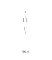
- FIG. 4 is a schematic vertical sectional view of a further embodiment of the device of the present invention.
- FIGS. 5-7 are flow diagrams showing different embodiments of the way in which the flows of humid and cold air may be positioned in relation to one another.
- FIG. 1 shows a schematic vertical sectional view of a preferred embodiment of the device of the present invention for carrying out the method of the present invention.
- the device comprises a single substantially closed chamber which comprises three zones 4 , 5 , and 6 , supply lines for humid air 1 and for cold air 9 entering the mixing zone 4 .
- supply lines for humid air 1 and for cold air 9 entering the mixing zone 4 .
- several supply lines are provided, which may, for example, be implemented in the form of one line with several outlets immediately below the chamber.
- the temperature of the flow of humid air should not increase to more than about +10° C. in order to prevent the need for an excessively large volume of cold air for obtaining a temperature below 0° C. within the chamber.
- the temperature should not normally be lower than ⁇ 5° C. either.
- FIG. 1 it is also possible to exchange the flows of humid and cold air in FIG. 1 , so that the numeral 9 would refer to the supply line for humid air, while 1 would refer to the supply line for cold air.
- an optionally heated water container could be provided immediately below the chamber, through which container ambient air is blown before entering the chamber as a flow of humid air, while cold air is laterally supplied.
- both an upward and a rotational movement, and thus a substantially helical movement are caused within the chamber which, above the mixing zone 4 , is provided in a shape tapered towards the top.
- the chamber is conical, which promotes the substantially helical movement of the atmosphere therein and allows for a more precise control of the residence time of the snowflakes growing therein.
- the optimum relation between the two air flows has to be selected depending on the structural implementation of the device of the present invention and the air temperatures. The only important things are that the air flows are mixed thoroughly and that the air temperature within the chamber is below the freezing point.
- a spatial separation which may consist of a perforated metal plate or the like and may result in a more thorough mixing of the two air flows in the mixing zone 4 and, occasionally, in the formation of a higher number of crystal nuclei, before the air mixture with the snowflakes growing therein enters the growth zone, is provided between the zones 4 and 5 .
- the formation of crystal nuclei usually occurs spontaneously when humid air and cold air meet, due to the air's resulting oversaturation with water.
- different additives may be supplied to the chamber together with one or both of the two air flows in order to facilitate the formation of crystal nuclei.
- the environmental compatibility of such optional additives has to be taken into account.
- Preferably, mainly additional ice crystal nuclei are supplied together with the cold air in order to obtain a higher density of growing snowflakes.
- the volume of the two air flows supplied per time unit has to be regulated in order to make sure that the snowflakes are allowed to grow within the device for a predetermined period of time, so that snowflakes of a desired size can be released.
- This period of time has to be determined empirically for every embodiment of the device of the present invention.
- the period of time should amount to at least 5 minutes, more preferably to at least 10 minutes, and especially to at least 15 minutes.
- the Venturi nozzle 7 is preferably operated with a flow of ambient air 2 which is optionally pre-cooled, which, however, is not preferred as it results in an increase of the energy required.
- the resulting carrier air flow 3 transports the snowflakes out of the device where they form a snow cover around the device.
- the pressure of the nozzle air flow 2 has to be selected adequately to make sure that only snowflakes of the predefined size are sucked in by the resulting negative pressure, i.e. to make sure that the release zone 6 does not extend to far down in the device.
- the pressure has to be sufficiently high for transporting the snowflakes with the carrier air flow 3 over an adequate distance away from the device in order to make it possible to cover with snow as large an area as possible around the device.
- the material the chamber is made from is not subject to any particular limitations.
- it is a light-weight material such as cloth, canvas, or plastic, a plastic film material, for example, in order to make the device transportable, and/or a material which inhibits the growth of ice crystals on the walls.
- some areas of the device may be lined with the latter material.
- some areas of the device may be cooled and/or heated, if desired.
- FIG. 2 is a schematic top view of the device of FIG. 1 , showing that the air flow 1 is supplied in a substantially tangential direction into the chamber, which favors the creation of a stable helical movement.
- FIG. 3 shows a schematic vertical sectional view of another embodiment of a device of the present invention for carrying out the method of the present invention.
- This figure shows two supply lines, one for humid air 1 and one for cold air 9 , leading into a cylindrical chamber with a dome-shaped top part (again, it is possible to exchange the positions of these supply lines).
- the chamber comprises two mixing zones 4 , which means that some of the snowflakes which have grown in the lower mixing zone 4 and have already moved to the growth zone 5 are contacted with additional smaller crystals having been generated in the upper mixing zone 4 . This triggers a second burst of growth, which results in a more rapid formation of larger snowflakes as well as in a higher flake density in the atmosphere within the chamber.
- the release zone 6 does not extend as far down into the chamber as described for the conical embodiment, which, if the chamber volume and the nozzle pressure are the same, results in a longer residence time of the snowflakes within the chamber.
- FIG. 4 is a schematic vertical sectional view of a further embodiment of a device of the present invention for carrying out the inventive method.
- three chambers 15 , 16 , and 17 are provided, each of which comprises a supply line 1 for humid air and a supply line 9 for cold air, the chambers 15 , 16 , and 17 being connected in series. This means that a snowflake growth mixture formed in chamber 15 is transferred to chamber 16 and, subsequently, to chamber 17 , so that in both chambers such a mixture is formed, too.
- each of the three chambers comprises a mixing zone, a growth zone, and a release zone (not shown), the release zones of the first two chambers 15 and 16 being limited to a very small area around the outlet of the respective chamber and the inlet of the transfer line leading into the next chamber.
- Only the last chamber 17 which is provided with a Venturi nozzle as a release opening 7 has a release zone which, due to the Venturi effect of the nozzle, extends further down into the chamber and from which snowflakes having the predefined size are sucked into the nozzle.
- the chambers may have the same or different sections, and the relation between the volume flows of the flow 1 of humid air and of the flow 9 of cold air may be the same or different in the chambers.
- FIG. 4 While the three chambers in FIG. 4 , for reasons of simplicity, are illustrated in a rectangular shape, all of them, especially chamber 17 , preferably have a circular section and a conical, upward tapered shape, in order to facilitate a helical movement of the air flow.
- the supply lines 1 and 9 are shown to enter the chambers at right angles, but at least one of the supply lines should enter the respective chamber at an oblique angle in order to guarantee the generation of the helical movement. If the chambers are constructed in the way shown in FIG. 4 , one or even several additional air flow control units such as fans and lateral deflector plates would be required per chamber, in order to provide the desired helical movement.
- the chambers which can be arbitrarily dimensioned, may be combined in all possible ways and connected in series or in parallel in order to reach the goals of the present invention, i.e. especially the production of snow which is as nature-identical as possible. What is important is that the growing snowflakes are kept floating in an oversaturated atmosphere, while they move along the helical trajectory, until their size has reached the predefined value.
- FIGS. 5 to 7 show three possible ways in which the two flows, one of humid air and one of cold air, can be mixed.
- the supply lines 1 and 9 form an angle of about 90°, so that, in addition to being mixed when they meet, the air flows are directed into a defined direction, which, in this case, is the direction of the angle's bisector, if the volume flows are equal.
- the two supply lines 1 and 9 form an angle of 180° and are facing each other, the supply line 9 having a significantly larger diameter than the supply line 1 .
- this can result in a larger volume of one air flow (in this case: of cold air) meeting a smaller volume of the other air flow, or in one air flow (again, in this case: of cold air) having a lower flow rate.
- both the direction and the temperature of the resulting air mixture and thus the growth conditions for the snowflakes may be controlled.
- FIG. 7 finally shows a case in which the supply line 1 for humid air is positioned, preferably concentrically, within the supply line 9 for cold air, which (if the material the lines are made of is appropriately selected) results in a heat exchange between the two lines, taking place even before the two air flows enter the chamber, so that the humid air flow is already oversaturated with water when entering the chamber.
- the supply line 1 already ends before its entry into the chamber (which is indicated as the upper end of the supply line 9 in the figure), which results in a partial pre-mixing of the two air flows before they enter the chamber.
- the device of the present invention consisted of a chamber in the form of a truncated cone with a height of 95 cm, a circular base with a diameter of 100 cm, and a circular top opening with a diameter of 10 cm.
- a plastic funnel with a height of 10 cm and a top opening diameter of 0.5 cm was placed on the top opening as a release nozzle, the bottom edge of the funnel being air-tightly glued to the outer surface of the chamber.
- the chamber thus had an overall height of 105 cm and an overall volume of about 0.27 m 3 .
- supply lines for humid and cold air one of which was positioned concentrically within the other, entered the chamber in a tangential direction, the supply line for humid air being positioned within the supply line for cold air.
- the entire device was cooled to a temperature of ⁇ 15° C.
- the flow of humid air was generated by blowing air through an ice-cooled flow cell filled with water having a temperature close to its freezing point, i.e. a temperature of 1 to 2° C., the air being thus saturated with vapor and subsequently enriched with tiny water droplets using an ultrasonic nebulizer, the water droplets serving the purpose of forming crystal nuclei.
- Ambient air from the cold laboratory having a temperature of ⁇ 15° C. was used as the cold air. Both air flows were supplied to the cooled chamber at a flow rate of between 0.2 and 0.3 L/s.
- the temperature of the humid air amounted to about +3° C., and the temperature within the chamber amounted to about ⁇ 14° C. Due to the fact that the air flows were supplied into the chamber in a tangential direction, the mixed air flows created an upward circular flow therein.
- the period of time during which the growing snowflakes remain within the chamber amounts to about 9 min.
- the device substantially corresponded to the device used in the first example, except for the fact that the humid air was enriched with water after having passed through the flow cell using finely dispersed water, which was obtained by a high-pressure atomizer instead of the ultrasonic nebulizer.
- the air flows were introduced into the chamber in the same way as described in Example 1, and the characteristics of the obtained snow practically corresponded to those of the snow produced in Example 1.
Landscapes
- Engineering & Computer Science (AREA)
- Physics & Mathematics (AREA)
- Mechanical Engineering (AREA)
- Thermal Sciences (AREA)
- General Engineering & Computer Science (AREA)
- Cultivation Of Plants (AREA)
- Materials Applied To Surfaces To Minimize Adherence Of Mist Or Water (AREA)
Applications Claiming Priority (4)
| Application Number | Priority Date | Filing Date | Title |
|---|---|---|---|
| ATA1434/2009 | 2009-09-11 | ||
| AT1434/2009 | 2009-09-11 | ||
| ATA1434/2009A AT508647B1 (de) | 2009-09-11 | 2009-09-11 | Verfahren und vorrichtung zur herstellung von künstlichem schnee |
| PCT/AT2010/000325 WO2011029115A2 (de) | 2009-09-11 | 2010-09-09 | Verfahren und vorrichtung zur herstellung von schnee |
Publications (2)
| Publication Number | Publication Date |
|---|---|
| US20120193440A1 US20120193440A1 (en) | 2012-08-02 |
| US9429348B2 true US9429348B2 (en) | 2016-08-30 |
Family
ID=43646093
Family Applications (1)
| Application Number | Title | Priority Date | Filing Date |
|---|---|---|---|
| US13/394,861 Expired - Fee Related US9429348B2 (en) | 2009-09-11 | 2010-09-09 | Method and device for producing snow |
Country Status (5)
| Country | Link |
|---|---|
| US (1) | US9429348B2 (de) |
| EP (1) | EP2475941A2 (de) |
| AT (1) | AT508647B1 (de) |
| CA (1) | CA2773276A1 (de) |
| WO (1) | WO2011029115A2 (de) |
Cited By (1)
| Publication number | Priority date | Publication date | Assignee | Title |
|---|---|---|---|---|
| US20170223907A1 (en) * | 2007-10-09 | 2017-08-10 | Leslie A. Field | Systems for maintaining and/or decreasing water temperature using high albedo materials |
Families Citing this family (5)
| Publication number | Priority date | Publication date | Assignee | Title |
|---|---|---|---|---|
| PL3765801T3 (pl) * | 2018-03-13 | 2022-04-04 | Thorsteinn I. VIGLUNDSSON | Sposób i urządzenie do wytwarzania mokrego śniegu |
| CN110260574B (zh) * | 2019-06-23 | 2020-12-08 | 安徽省华腾农业科技有限公司经开区分公司 | 一种人工造雪设备 |
| AT523604A1 (de) | 2020-03-04 | 2021-09-15 | Elbimex Tech E U | Verfahren zur Erzeugung von schneekristallähnlichen wasserhaltigen Strukturen |
| CN113830328B (zh) * | 2021-11-30 | 2022-02-18 | 中国飞机强度研究所 | 一种飞机整机测试降雪环境模拟装置及模拟方法 |
| DE202022107105U1 (de) * | 2022-12-20 | 2023-03-08 | Technische Universität Chemnitz, Körperschaft des öffentlichen Rechts | Anlage zur Abkühlung mindestens eines Kältemittels und/oder mindestens eines Kälteträgers in einem offenen Prozess |
Citations (22)
| Publication number | Priority date | Publication date | Assignee | Title |
|---|---|---|---|---|
| US3257815A (en) | 1964-07-10 | 1966-06-28 | Conch Int Methane Ltd | Method and apparatus for the largescale production of snow fields for sports use |
| US3408005A (en) * | 1966-05-09 | 1968-10-29 | Willard R. Struble | Snow making nozzle |
| US3703991A (en) * | 1971-07-23 | 1972-11-28 | Hedco | Snow precipitator |
| US3831844A (en) * | 1972-02-17 | 1974-08-27 | J Tropeano | Apparatus for snow making |
| US3969908A (en) * | 1975-04-29 | 1976-07-20 | Lawless John F | Artificial snow making method |
| SU951031A1 (ru) | 1980-06-19 | 1982-08-15 | Иркутский государственный научно-исследовательский институт редких и цветных металлов | Установка дл получени искусственного снега |
| US4475688A (en) * | 1982-09-27 | 1984-10-09 | Hodges James L | Artificial snow making |
| US4746064A (en) | 1986-10-17 | 1988-05-24 | Suga Weathering Technology Foundation | Snow generating and snowfall apparatus |
| US4767054A (en) | 1987-01-23 | 1988-08-30 | Suga Test Instruments Co., Ltd. | Apparatus for changing artificial snow to wet snow |
| US4792093A (en) | 1987-03-04 | 1988-12-20 | Suga Test Instruments Co., Ltd. | Artificial snow wetting apparatus |
| US4809514A (en) | 1987-02-09 | 1989-03-07 | Suga Test Instruments Co., Ltd. | Apparatus for removing snow deposited on wall of snow generating apparatus |
| SU1617272A1 (ru) | 1988-03-25 | 1990-12-30 | В.М. Шлейников | Снегогенератор |
| GB2241316A (en) | 1990-02-09 | 1991-08-28 | Toyo Seisakusho Kk | Artificial snowfall system |
| JPH05312448A (ja) | 1992-05-12 | 1993-11-22 | Mitsui Constr Co Ltd | 氷雪粒径調整装置 |
| JPH067151B2 (ja) | 1987-05-15 | 1994-01-26 | ロ−ム株式会社 | 電子装置用測定装置 |
| JPH0634245A (ja) | 1992-07-16 | 1994-02-08 | Mitsubishi Heavy Ind Ltd | 人工造雪装置 |
| EP0609140A1 (de) | 1993-01-26 | 1994-08-03 | Compagnie Francaise D'etudes Et De Construction "Technip" | Verfahren und Anlage zur Schnee-Erzeugung |
| JPH08178492A (ja) | 1994-12-27 | 1996-07-12 | Nkk Corp | ヒラヒラ雪発生装置およびヒラヒラ雪発生方法 |
| WO2000066957A2 (en) | 1999-05-03 | 2000-11-09 | Aquatrols Corporation Of America, Inc. | Snowmaking process |
| EP1065456A1 (de) | 1989-03-01 | 2001-01-03 | Polar Technologies International Pty Limited | Verfahren und Vorrichtung zur Herstellung von Schnee |
| US6402047B1 (en) * | 1999-10-29 | 2002-06-11 | Kevin S. Thomas | Snow making apparatus and method |
| EP1710519A1 (de) | 2005-04-08 | 2006-10-11 | Lenko Snow AB | Schneeerzeugungsprozess und entsprechende Vorrichtung |
Family Cites Families (3)
| Publication number | Priority date | Publication date | Assignee | Title |
|---|---|---|---|---|
| JPH0467151A (ja) | 1990-07-09 | 1992-03-03 | Fuji Photo Film Co Ltd | 電子写真式平版印刷用原版 |
| RU2226249C2 (ru) * | 2001-10-04 | 2004-03-27 | Кастерин Дмитрий Сергеевич | Устройство для получения искусственного снега |
| DE10329947B8 (de) * | 2003-04-03 | 2005-08-25 | Innovag AG Aktiengesellschaft für innovative Industrietechnik | Beschneiungssystem für Innenräume sowie Innenraum mit einem solchen Beschneiungssystem |
-
2009
- 2009-09-11 AT ATA1434/2009A patent/AT508647B1/de not_active IP Right Cessation
-
2010
- 2010-09-09 US US13/394,861 patent/US9429348B2/en not_active Expired - Fee Related
- 2010-09-09 EP EP10770939A patent/EP2475941A2/de not_active Withdrawn
- 2010-09-09 CA CA2773276A patent/CA2773276A1/en not_active Abandoned
- 2010-09-09 WO PCT/AT2010/000325 patent/WO2011029115A2/de not_active Ceased
Patent Citations (23)
| Publication number | Priority date | Publication date | Assignee | Title |
|---|---|---|---|---|
| US3257815A (en) | 1964-07-10 | 1966-06-28 | Conch Int Methane Ltd | Method and apparatus for the largescale production of snow fields for sports use |
| US3408005A (en) * | 1966-05-09 | 1968-10-29 | Willard R. Struble | Snow making nozzle |
| US3703991A (en) * | 1971-07-23 | 1972-11-28 | Hedco | Snow precipitator |
| US3831844A (en) * | 1972-02-17 | 1974-08-27 | J Tropeano | Apparatus for snow making |
| US3969908A (en) * | 1975-04-29 | 1976-07-20 | Lawless John F | Artificial snow making method |
| SU951031A1 (ru) | 1980-06-19 | 1982-08-15 | Иркутский государственный научно-исследовательский институт редких и цветных металлов | Установка дл получени искусственного снега |
| US4475688A (en) * | 1982-09-27 | 1984-10-09 | Hodges James L | Artificial snow making |
| US4746064A (en) | 1986-10-17 | 1988-05-24 | Suga Weathering Technology Foundation | Snow generating and snowfall apparatus |
| US4767054A (en) | 1987-01-23 | 1988-08-30 | Suga Test Instruments Co., Ltd. | Apparatus for changing artificial snow to wet snow |
| US4809514A (en) | 1987-02-09 | 1989-03-07 | Suga Test Instruments Co., Ltd. | Apparatus for removing snow deposited on wall of snow generating apparatus |
| US4792093A (en) | 1987-03-04 | 1988-12-20 | Suga Test Instruments Co., Ltd. | Artificial snow wetting apparatus |
| JPH067151B2 (ja) | 1987-05-15 | 1994-01-26 | ロ−ム株式会社 | 電子装置用測定装置 |
| SU1617272A1 (ru) | 1988-03-25 | 1990-12-30 | В.М. Шлейников | Снегогенератор |
| EP1065456A1 (de) | 1989-03-01 | 2001-01-03 | Polar Technologies International Pty Limited | Verfahren und Vorrichtung zur Herstellung von Schnee |
| GB2241316A (en) | 1990-02-09 | 1991-08-28 | Toyo Seisakusho Kk | Artificial snowfall system |
| JPH05312448A (ja) | 1992-05-12 | 1993-11-22 | Mitsui Constr Co Ltd | 氷雪粒径調整装置 |
| JPH0634245A (ja) | 1992-07-16 | 1994-02-08 | Mitsubishi Heavy Ind Ltd | 人工造雪装置 |
| EP0609140A1 (de) | 1993-01-26 | 1994-08-03 | Compagnie Francaise D'etudes Et De Construction "Technip" | Verfahren und Anlage zur Schnee-Erzeugung |
| US5445320A (en) | 1993-01-26 | 1995-08-29 | Technip | Method of and equipment for snow production |
| JPH08178492A (ja) | 1994-12-27 | 1996-07-12 | Nkk Corp | ヒラヒラ雪発生装置およびヒラヒラ雪発生方法 |
| WO2000066957A2 (en) | 1999-05-03 | 2000-11-09 | Aquatrols Corporation Of America, Inc. | Snowmaking process |
| US6402047B1 (en) * | 1999-10-29 | 2002-06-11 | Kevin S. Thomas | Snow making apparatus and method |
| EP1710519A1 (de) | 2005-04-08 | 2006-10-11 | Lenko Snow AB | Schneeerzeugungsprozess und entsprechende Vorrichtung |
Non-Patent Citations (7)
| Title |
|---|
| Fierz et al, "The International Classification for Seasonal Snow on the Ground", IHP-VII Technical Documents in Hydrology, No. 83, IACD Contribution No. 1, UNESCO-IHP, Paris (2009). |
| Hahn, "Künstliche Beschneiung im Alpenraum" ("The production of artificial snow in the Alpine region"), Cipra International, pp. 1-18 (2004). |
| Int'l Search Report issued Oct. 28, 2011 in Int'l Application No. PCT/AT2010/000325. |
| Meier, "Produktion von naturidentischem Schnee" ("Producing nature-identical snow"), Diploma Thesis, ETH Zurich (2006). |
| Office Action issued Apr. 12, 2012 in AT Application No. 2B A 1434/2009. |
| Office Action issued Aug. 17, 2010 in AT Application No. 2B A 1434/2009. |
| Rixen et al, "Does artificial snow production affect soil and vegetation of ski pistes? A review", Perspectives in Plant Ecology, Evolution and Systematics, vol. 5/4, pp. 219-230 (2003). |
Cited By (2)
| Publication number | Priority date | Publication date | Assignee | Title |
|---|---|---|---|---|
| US20170223907A1 (en) * | 2007-10-09 | 2017-08-10 | Leslie A. Field | Systems for maintaining and/or decreasing water temperature using high albedo materials |
| US10701871B2 (en) * | 2007-10-09 | 2020-07-07 | Leslie A Field | Systems for maintaining and/or decreasing water temperature using high albedo materials |
Also Published As
| Publication number | Publication date |
|---|---|
| EP2475941A2 (de) | 2012-07-18 |
| WO2011029115A2 (de) | 2011-03-17 |
| WO2011029115A3 (de) | 2011-12-29 |
| CA2773276A1 (en) | 2011-03-17 |
| AT508647A1 (de) | 2011-03-15 |
| US20120193440A1 (en) | 2012-08-02 |
| AT508647B1 (de) | 2015-03-15 |
Similar Documents
| Publication | Publication Date | Title |
|---|---|---|
| US9429348B2 (en) | Method and device for producing snow | |
| US20130264032A1 (en) | Snow/ ice making & preserving methods | |
| JP2531995B2 (ja) | 雪製造装置 | |
| EP0817575A1 (de) | Tropfersystem für flüssigkeitszufuhr und zufuhrverfahren von flüssigen zusammensetzungen ins gefrierraum | |
| CN204948921U (zh) | 一种带降温作用的植物种植大棚 | |
| US5297731A (en) | Snow making apparatus | |
| JP3397582B2 (ja) | 人工結晶雪製造装置 | |
| US6464148B1 (en) | Snowmaking process | |
| JP7348855B2 (ja) | 降雪装置、人工気象室及び降雪方法 | |
| JPH0293267A (ja) | 室内スキー場における造雪方法および造雪装置 | |
| JP7312126B2 (ja) | 降雪装置、人工気象室及び降雪方法 | |
| EP3967955B1 (de) | Temporäres energiespeichersystem für kälteenergie | |
| JPH07174435A (ja) | 熱回収装置 | |
| EP1444469A1 (de) | Schneeherstellung | |
| US4746064A (en) | Snow generating and snowfall apparatus | |
| JPS62255770A (ja) | 雪の製造方法及びその装置 | |
| JPH0370157B2 (de) | ||
| JP7559138B2 (ja) | 降雪装置、人工気象室及び降雪方法 | |
| JPH06103135B2 (ja) | 人工降雪装置 | |
| CN111750584A (zh) | 降雪装置、人工气象室以及降雪方法 | |
| JPS6242227B2 (de) | ||
| JP3051713U (ja) | 低温高湿度貯蔵庫、並びに製氷庫 | |
| JPS63140269A (ja) | 人工降雪湿雪化装置 | |
| AU642696B2 (en) | Snow making apparatus | |
| JPH02254274A (ja) | 流下式製氷方法及び氷温貯蔵庫 |
Legal Events
| Date | Code | Title | Description |
|---|---|---|---|
| AS | Assignment |
Owner name: UNIVERSITAT FUR BODENKULTUR WIEN, AUSTRIA Free format text: ASSIGNMENT OF ASSIGNORS INTEREST;ASSIGNORS:BREILING, MEINHARD;BACHER, MICHAEL;SOKRATOV, SERGEY;AND OTHERS;SIGNING DATES FROM 20120301 TO 20120302;REEL/FRAME:028037/0024 Owner name: TECHNISCHE UNIVERSITAT WIEN, AUSTRIA Free format text: ASSIGNMENT OF ASSIGNORS INTEREST;ASSIGNORS:BREILING, MEINHARD;BACHER, MICHAEL;SOKRATOV, SERGEY;AND OTHERS;SIGNING DATES FROM 20120301 TO 20120302;REEL/FRAME:028037/0024 |
|
| ZAAA | Notice of allowance and fees due |
Free format text: ORIGINAL CODE: NOA |
|
| ZAAB | Notice of allowance mailed |
Free format text: ORIGINAL CODE: MN/=. |
|
| STCF | Information on status: patent grant |
Free format text: PATENTED CASE |
|
| MAFP | Maintenance fee payment |
Free format text: PAYMENT OF MAINTENANCE FEE, 4TH YR, SMALL ENTITY (ORIGINAL EVENT CODE: M2551); ENTITY STATUS OF PATENT OWNER: SMALL ENTITY Year of fee payment: 4 |
|
| AS | Assignment |
Owner name: NEUSCHNEE SPORTS GMBH, AUSTRIA Free format text: ASSIGNMENT OF ASSIGNORS INTEREST;ASSIGNORS:TECHNISCHE UNIVERSITAET WIEN;UNIVERSITAET FUER BODENKULTUR WIEN;SIGNING DATES FROM 20230228 TO 20230327;REEL/FRAME:063496/0081 |
|
| FEPP | Fee payment procedure |
Free format text: MAINTENANCE FEE REMINDER MAILED (ORIGINAL EVENT CODE: REM.); ENTITY STATUS OF PATENT OWNER: SMALL ENTITY |
|
| LAPS | Lapse for failure to pay maintenance fees |
Free format text: PATENT EXPIRED FOR FAILURE TO PAY MAINTENANCE FEES (ORIGINAL EVENT CODE: EXP.); ENTITY STATUS OF PATENT OWNER: SMALL ENTITY |
|
| STCH | Information on status: patent discontinuation |
Free format text: PATENT EXPIRED DUE TO NONPAYMENT OF MAINTENANCE FEES UNDER 37 CFR 1.362 |
|
| FP | Lapsed due to failure to pay maintenance fee |
Effective date: 20240830 |