US9253297B2 - Sound-transmitting membrane for microphone, sound-transmitting membrane member for microphone provided with the membrane, microphone, and electronic device provided with microphone - Google Patents
Sound-transmitting membrane for microphone, sound-transmitting membrane member for microphone provided with the membrane, microphone, and electronic device provided with microphone Download PDFInfo
- Publication number
- US9253297B2 US9253297B2 US13/141,934 US201013141934A US9253297B2 US 9253297 B2 US9253297 B2 US 9253297B2 US 201013141934 A US201013141934 A US 201013141934A US 9253297 B2 US9253297 B2 US 9253297B2
- Authority
- US
- United States
- Prior art keywords
- sound
- transmitting membrane
- microphone
- membrane
- transmitting
- Prior art date
- Legal status (The legal status is an assumption and is not a legal conclusion. Google has not performed a legal analysis and makes no representation as to the accuracy of the status listed.)
- Active, expires
Links
- 239000012528 membrane Substances 0.000 title claims abstract description 266
- 230000005540 biological transmission Effects 0.000 claims abstract description 41
- 239000000853 adhesive Substances 0.000 claims description 26
- 230000001070 adhesive effect Effects 0.000 claims description 26
- 230000035699 permeability Effects 0.000 claims description 22
- 230000002093 peripheral effect Effects 0.000 claims description 12
- 239000011148 porous material Substances 0.000 claims description 5
- 238000004891 communication Methods 0.000 claims description 4
- XLYOFNOQVPJJNP-UHFFFAOYSA-N water Chemical compound O XLYOFNOQVPJJNP-UHFFFAOYSA-N 0.000 abstract description 15
- 239000000428 dust Substances 0.000 abstract description 14
- 229920001343 polytetrafluoroethylene Polymers 0.000 description 17
- 239000004810 polytetrafluoroethylene Substances 0.000 description 17
- 238000000034 method Methods 0.000 description 9
- 239000010410 layer Substances 0.000 description 8
- 230000000052 comparative effect Effects 0.000 description 7
- 239000011347 resin Substances 0.000 description 7
- 229920005989 resin Polymers 0.000 description 7
- 238000003466 welding Methods 0.000 description 6
- -1 polyethylene Polymers 0.000 description 5
- 238000011156 evaluation Methods 0.000 description 4
- 239000002184 metal Substances 0.000 description 4
- 229920000728 polyester Polymers 0.000 description 4
- 239000004698 Polyethylene Substances 0.000 description 3
- 239000003990 capacitor Substances 0.000 description 3
- 239000000463 material Substances 0.000 description 3
- 229920000573 polyethylene Polymers 0.000 description 3
- 229920002799 BoPET Polymers 0.000 description 2
- OKTJSMMVPCPJKN-UHFFFAOYSA-N Carbon Chemical compound [C] OKTJSMMVPCPJKN-UHFFFAOYSA-N 0.000 description 2
- 239000004642 Polyimide Substances 0.000 description 2
- 239000002131 composite material Substances 0.000 description 2
- 230000005494 condensation Effects 0.000 description 2
- 238000009833 condensation Methods 0.000 description 2
- 230000003247 decreasing effect Effects 0.000 description 2
- 230000000694 effects Effects 0.000 description 2
- 239000004745 nonwoven fabric Substances 0.000 description 2
- 239000002245 particle Substances 0.000 description 2
- 229920001721 polyimide Polymers 0.000 description 2
- 239000002356 single layer Substances 0.000 description 2
- 238000012360 testing method Methods 0.000 description 2
- 239000002759 woven fabric Substances 0.000 description 2
- 239000004925 Acrylic resin Substances 0.000 description 1
- 229920000178 Acrylic resin Polymers 0.000 description 1
- 239000004677 Nylon Substances 0.000 description 1
- 239000004952 Polyamide Substances 0.000 description 1
- XUIMIQQOPSSXEZ-UHFFFAOYSA-N Silicon Chemical compound [Si] XUIMIQQOPSSXEZ-UHFFFAOYSA-N 0.000 description 1
- 239000004699 Ultra-high molecular weight polyethylene Substances 0.000 description 1
- 239000004760 aramid Substances 0.000 description 1
- 229920003235 aromatic polyamide Polymers 0.000 description 1
- 230000006866 deterioration Effects 0.000 description 1
- 239000000835 fiber Substances 0.000 description 1
- 239000006260 foam Substances 0.000 description 1
- 238000003475 lamination Methods 0.000 description 1
- 238000005259 measurement Methods 0.000 description 1
- 239000000203 mixture Substances 0.000 description 1
- 238000000465 moulding Methods 0.000 description 1
- 229910052757 nitrogen Inorganic materials 0.000 description 1
- IJGRMHOSHXDMSA-UHFFFAOYSA-N nitrogen Substances N#N IJGRMHOSHXDMSA-UHFFFAOYSA-N 0.000 description 1
- QJGQUHMNIGDVPM-UHFFFAOYSA-N nitrogen group Chemical group [N] QJGQUHMNIGDVPM-UHFFFAOYSA-N 0.000 description 1
- 229920001778 nylon Polymers 0.000 description 1
- 229920002647 polyamide Polymers 0.000 description 1
- 229920000515 polycarbonate Polymers 0.000 description 1
- 239000004417 polycarbonate Substances 0.000 description 1
- 229920000098 polyolefin Polymers 0.000 description 1
- 239000000843 powder Substances 0.000 description 1
- 238000007665 sagging Methods 0.000 description 1
- 229910052710 silicon Inorganic materials 0.000 description 1
- 239000010703 silicon Substances 0.000 description 1
- 239000007787 solid Substances 0.000 description 1
- 229910001220 stainless steel Inorganic materials 0.000 description 1
- 239000010935 stainless steel Substances 0.000 description 1
- 239000000126 substance Substances 0.000 description 1
- 229920000785 ultra high molecular weight polyethylene Polymers 0.000 description 1
Images


Classifications
-
- H—ELECTRICITY
- H04—ELECTRIC COMMUNICATION TECHNIQUE
- H04R—LOUDSPEAKERS, MICROPHONES, GRAMOPHONE PICK-UPS OR LIKE ACOUSTIC ELECTROMECHANICAL TRANSDUCERS; DEAF-AID SETS; PUBLIC ADDRESS SYSTEMS
- H04R1/00—Details of transducers, loudspeakers or microphones
- H04R1/08—Mouthpieces; Microphones; Attachments therefor
-
- H—ELECTRICITY
- H04—ELECTRIC COMMUNICATION TECHNIQUE
- H04M—TELEPHONIC COMMUNICATION
- H04M1/00—Substation equipment, e.g. for use by subscribers
- H04M1/02—Constructional features of telephone sets
- H04M1/03—Constructional features of telephone transmitters or receivers, e.g. telephone hand-sets
-
- H—ELECTRICITY
- H04—ELECTRIC COMMUNICATION TECHNIQUE
- H04M—TELEPHONIC COMMUNICATION
- H04M1/00—Substation equipment, e.g. for use by subscribers
- H04M1/02—Constructional features of telephone sets
-
- H—ELECTRICITY
- H04—ELECTRIC COMMUNICATION TECHNIQUE
- H04R—LOUDSPEAKERS, MICROPHONES, GRAMOPHONE PICK-UPS OR LIKE ACOUSTIC ELECTROMECHANICAL TRANSDUCERS; DEAF-AID SETS; PUBLIC ADDRESS SYSTEMS
- H04R1/00—Details of transducers, loudspeakers or microphones
-
- H—ELECTRICITY
- H04—ELECTRIC COMMUNICATION TECHNIQUE
- H04R—LOUDSPEAKERS, MICROPHONES, GRAMOPHONE PICK-UPS OR LIKE ACOUSTIC ELECTROMECHANICAL TRANSDUCERS; DEAF-AID SETS; PUBLIC ADDRESS SYSTEMS
- H04R1/00—Details of transducers, loudspeakers or microphones
- H04R1/02—Casings; Cabinets ; Supports therefor; Mountings therein
-
- H—ELECTRICITY
- H04—ELECTRIC COMMUNICATION TECHNIQUE
- H04R—LOUDSPEAKERS, MICROPHONES, GRAMOPHONE PICK-UPS OR LIKE ACOUSTIC ELECTROMECHANICAL TRANSDUCERS; DEAF-AID SETS; PUBLIC ADDRESS SYSTEMS
- H04R1/00—Details of transducers, loudspeakers or microphones
- H04R1/08—Mouthpieces; Microphones; Attachments therefor
- H04R1/083—Special constructions of mouthpieces
- H04R1/086—Protective screens, e.g. all weather or wind screens
-
- H—ELECTRICITY
- H04—ELECTRIC COMMUNICATION TECHNIQUE
- H04R—LOUDSPEAKERS, MICROPHONES, GRAMOPHONE PICK-UPS OR LIKE ACOUSTIC ELECTROMECHANICAL TRANSDUCERS; DEAF-AID SETS; PUBLIC ADDRESS SYSTEMS
- H04R1/00—Details of transducers, loudspeakers or microphones
- H04R1/20—Arrangements for obtaining desired frequency or directional characteristics
- H04R1/22—Arrangements for obtaining desired frequency or directional characteristics for obtaining desired frequency characteristic only
- H04R1/28—Transducer mountings or enclosures modified by provision of mechanical or acoustic impedances, e.g. resonator, damping means
- H04R1/2807—Enclosures comprising vibrating or resonating arrangements
- H04R1/2838—Enclosures comprising vibrating or resonating arrangements of the bandpass type
-
- H—ELECTRICITY
- H04—ELECTRIC COMMUNICATION TECHNIQUE
- H04R—LOUDSPEAKERS, MICROPHONES, GRAMOPHONE PICK-UPS OR LIKE ACOUSTIC ELECTROMECHANICAL TRANSDUCERS; DEAF-AID SETS; PUBLIC ADDRESS SYSTEMS
- H04R9/00—Transducers of moving-coil, moving-strip, or moving-wire type
- H04R9/08—Microphones
Definitions
- the present invention relates to a sound-transmitting membrane for a microphone that allows sound to transmit through the sound-transmitting membrane to a sound transducer of the microphone while preventing a foreign matter from entering into the sound transducer.
- the present invention also relates to a sound-transmitting membrane member for a microphone including the sound-transmitting membrane, a microphone, and an electronic device having a microphone.
- the microphone of these electronic devices is a compact capacitor microphone.
- the microphone is accommodated in a casing of the electronic device as a microphone unit in which a sound transducer (sound-collecting part) having a diaphragm and a back plate is accommodated in a housing of the unit.
- the sound from the outside is guided to the sound transducer of the microphone through both a sound-collecting opening provided to the casing and a sound-collecting opening provided to the housing.
- a sound-transmitting membrane that allows sound to transmit through the sound-transmitting membrane while preventing the entry of the foreign matter generally is disposed at the sound-collecting opening of at least one member selected from the casing and the housing. Disposing the sound-transmitting membrane also suppresses the noise generated by the blow-in of wind or breath.
- JP 2008-199225 A discloses that a woven fabric or nonwoven fabric produced from fibers made of a resin, such as nylon and polyethylene, can be used as a sound-transmitting membrane.
- JP 2007-81881 A discloses that a porous polytetrafluoroethylene (PTFE) membrane can be used as a sound-transmitting membrane. The latter sound-transmitting membrane is expected to suppress the entry of water as well as dust, as foreign matters, judging from the properties of the porous PTFE membrane.
- PTFE polytetrafluoroethylene
- a porous sheet is used as a sound-transmitting membrane
- its air permeability makes it difficult to prevent the entry of fine dust.
- a sound-transmitting membrane is used also for a sound emitting part, such as a speaker and a buzzer, of an electronic device as is used for a microphone
- the fine dust hardly be a problem to the sound emitting part.
- the fine dust is a serious problem to the microphone because it generates noise and causes a failure to the microphone. Therefore, a sound-transmitting membrane that prevents the entry of fine dust is desired.
- a porous sheet (porous membrane) having air permeability conventionally has been used as the sound-transmitting membrane for a microphone, and a membrane having no air permeability has not been used. This is because it has been thought essential for the sound-transmitting membrane to have air permeability to ensure the microphone performance. It always has been a common technical knowledge for a person skilled in the art to use a porous sheet having air permeability as the sound-transmitting membrane for a microphone. Challenging this common technical knowledge, the present inventors studied anew whether the air permeability of the sound-transmitting membrane is essential to ensure the microphone performance. As a result, they found the following, although quite unexpected.
- a sound-transmitting membrane has air permeability does not so much affect the sound pressure of the sound that is transmitting through the membrane, although it affects significantly the distortion of the sound that is transmitting through the membrane (in the case where the sound-transmitting membrane has no air permeability, the sound distortion caused when the sound transmits through the membrane is larger than in the case where the sound-transmitting membrane has air permeability).
- the present inventors have found that actually the sound-transmitting membrane for a microphone does not necessarily have to have air permeability to ensure the microphone performance, and that the microphone performance is ensured, under given conditions, also in the case where a nonporous film having no air permeability is used as the sound-transmitting membrane for a microphone.
- the present invention provides a sound-transmitting membrane for a microphone, to be disposed to a sound-collecting opening of the microphone so as to allow sound to transmit through the sound-transmitting membrane while preventing a foreign matter from entering into a sound transducer of the microphone through the sound-collecting opening.
- the sound-transmitting membrane according to the present invention is composed of a nonporous film or a multilayer membrane including a nonporous film, has a surface density of 30 g/m 2 or less, and has a sound transmission loss of less than 3 dB in a frequency range of 300 to 4000 Hz.
- the present invention provides a sound-transmitting membrane member for a microphone, including: a sound-transmitting membrane to be disposed to a sound-collecting opening of the microphone and/or a sound-collecting opening of a casing of an electronic device having the microphone so as to allow sound to transmit through the sound-transmitting membrane while preventing a foreign matter from entering into a sound transducer of the microphone through the sound-collecting opening; and a double-sided adhesive sheet for bonding the sound-transmitting membrane to a member having the sound-collecting opening so as to cover the sound-collecting opening.
- the sound-transmitting membrane is the sound-transmitting membrane for a microphone according to the present invention.
- the double-sided adhesive sheet is placed on a peripheral portion of at least one main surface of the sound-transmitting membrane.
- the present invention provides a microphone including: a sound transducer; a housing that accommodates the sound transducer and has a sound-collecting opening for guiding sound to the sound transducer; and a sound-transmitting membrane that is bonded to the housing so as to cover the sound-collecting opening and allows sound to transmit through the sound-transmitting membrane while preventing a foreign matter from entering into the sound transducer through the sound-collecting opening.
- the sound-transmitting membrane is the sound-transmitting membrane for a microphone according to the present invention.
- the present invention provides an electronic device having a microphone, including: a microphone including a sound transducer and a housing that accommodates the sound transducer and has a sound-collecting opening for guiding sound to the sound transducer; a casing that accommodates the microphone and has a sound-collecting opening for guiding sound to the microphone; and a sound-transmitting membrane that is bonded to at least one member selected from the housing and the casing so as to cover the sound-collecting opening of the at least one member and that allows sound to transmit through the sound-transmitting membrane while preventing a foreign matter from entering into the sound transducer through the sound-collecting opening of the at least one member.
- the sound-transmitting membrane is the sound-transmitting membrane for a microphone according to the present invention.
- the sound-transmitting membrane for a microphone according to the present invention is composed of a nonporous film or a multilayer membrane including a nonporous film. Thus, it can prevent a foreign matter, such as fine dust, that is difficult for conventional sound-transmitting membranes to block from entering into the sound transducer of the microphone. Also, the sound-transmitting membrane for a microphone according to the present invention can prevent water vapor (the breath of a speaker contains a significantly large amount of water vapor) from entering into the sound transducer, and can suppress the water condensation at the sound transducer, which is observed with the conventional sound-transmitting membranes.
- the sound-transmitting membrane is able to have a surface density of 30 g/m 2 or less and a sound transmission loss of less than 3 dB in a frequency range of 300 to 4000 Hz.
- the microphone according to the present invention including such a sound-transmitting membrane is highly reliable because the noise generation and failure caused by the entry of a foreign matter into the sound transducer are reduced.
- FIG. 1 is a cross-sectional view showing schematically an example of the sound-transmitting membrane for a microphone according to the present invention.
- FIG. 2 is a cross-sectional view showing schematically another example of the sound-transmitting membrane for a microphone according to the present invention.
- FIG. 3 is a perspective view showing schematically an example of the sound-transmitting membrane member for a microphone according to the present invention.
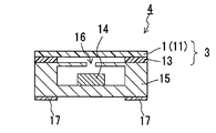
- FIG. 4 is a cross-sectional view showing schematically an example of the microphone according to the present invention.
- FIG. 5 is a cross-sectional view showing schematically an example of the electronic device having a microphone according to the present invention.
- FIG. 6 is a cross-sectional view showing schematically another example of the electronic device having a microphone according to the present invention.
- FIG. 7 is a cross-sectional view showing schematically still another example of the electronic device having a microphone according to the present invention.
- FIG. 8 is a cross-sectional view showing schematically further still another example of the electronic device having a microphone according to the present invention.
- FIG. 9 is a schematic view for explaining the method for evaluating the sound transmission loss of the sound-transmitting membrane, used in Examples.
- FIG. 1 shows an example of the sound-transmitting membrane for a microphone according to the present invention.
- a sound-transmitting membrane for a microphone (hereinafter referred to simply as a “sound-transmitting membrane”) 1 shown in FIG. 1 is a nonporous film 11 .
- the sound-transmitting membrane 1 has a surface density of 30 g/m 2 or less.
- the surface density of the sound-transmitting membrane 1 is a value obtained by dividing the weight of the membrane by the area of a main surface of the membrane. In other words, the surface density is a weight per unit area of the main surface of the sound-transmitting membrane 1 .
- the surface density of the sound-transmitting membrane affects significantly the variation in sound pressure when the sound transmits through the membrane.
- the sound-transmitting membrane 1 has a sound transmission loss of less than 3 dB in a frequency range of 300 to 4000 Hz.
- the sound-transmitting membrane 1 can ensure the microphone performance at the time of use, that is, when the sound-transmitting membrane 1 is disposed to a sound-collecting opening for guiding sound to the sound transducer of the microphone.
- the sound transmission loss is a value reflecting a variation in sound pressure (sound pressure loss) when the sound transmits through an object to be evaluated. When the sound transmission loss is less than 3 dB, a variation therein cannot be sensed by human hearing.
- the sound transmission loss in a frequency range of 300 to 4000 Hz indicates an average value of sound transmission losses in this frequency range.
- the sound transmission loss in the frequency range of 300 to 4000 Hz is referred to simply as a “sound transmission loss.”
- the frequency of 300 to 4000 Hz corresponds to the frequency of human voice.
- the surface density of the sound-transmitting membrane 1 is 25 g/m 2 or less, more preferably 20 g/m 2 or less, and further preferably 15 g/m 2 or less. In this case, the sound transmission loss of the sound-transmitting membrane 1 is further decreased.
- the lower limit of the surface density of the sound-transmitting membrane 1 is not particularly limited, and it is 1 g/m 2 , for example. Preferably, the lower limit is 10 g/m 2 .
- An excessively small surface density lowers the strength of the sound-transmitting membrane 1 , making the sound-transmitting membrane 1 vulnerable to a damage caused by a foreign matter.
- the surface density of the sound-transmitting membrane 1 falls between the lower limit or preferable lower limit, and the upper limit or preferable upper limit.
- the lower limit of the sound transmission loss of the sound-transmitting membrane 1 is not particularly limited. From the viewpoint of microphone performance, a smaller sound transmission loss is better.
- the lower limit of the sound transmission loss of the sound-transmitting membrane 1 is 0.5 dB, for example.
- the sound transmission loss of the sound-transmitting membrane 1 is 0.5 dB or more but less than 3 dB, for example.
- the structure and material of the nonporous film 11 are not particularly limited.
- the nonporous film 11 is made of, for example, metal or resin, or a composite material of these.
- the nonporous film 11 is a resin film.
- the type of the resin is not particularly limited. Polytetrafluoroethylene (PTFE), polyester (PET), polycarbonate, polyethylene (PE), and polyimide can be used, for example.
- PTFE polytetrafluoroethylene
- PET polyester
- PET polycarbonate
- PE polyethylene
- polyimide polyimide
- nonporous means that no fine pore that brings one main surface of the film into communication with the other main surface is present.
- a film in which the air permeability between one main surface and the other main surface is zero can be determined as a nonporous film.
- the nonporous film 11 is a PTFE film or a PET film because they have a weight and a strength in good balance.
- the PTFE film is preferable.
- the thickness of the nonporous film 11 is not particularly limited as long as the nonporous film 11 has a surface density of 30 g/m 2 or less and a sound transmission loss of less than 3 dB when serving as the sound-transmitting membrane 1 .
- the sound-transmitting membrane 1 may be composed of two or more layers of nonporous films 11 .
- the types of these nonporous films 11 may be the same as or different from each other. From the viewpoint of minimizing the sound transmission loss of the sound-transmitting membrane 1 , it is preferable that the sound-transmitting membrane 1 is a single layer membrane composed of the nonporous film 11 as shown in FIG. 1 .
- FIG. 2 shows another example of the sound-transmitting membrane according to the present invention.
- a sound-transmitting membrane 2 shown in FIG. 2 is a multilayer membrane composed of the nonporous film 11 and an air-permeable supporting member 12 .
- the surface density of the sound-transmitting membrane 2 (the surface density of the multilayer membrane including the nonporous film 11 and the air-permeable supporting member 12 ) is 30 g/m 2 or less. Moreover, the sound transmission loss of the sound-transmitting membrane 2 is less than 3 dB. Thereby, the sound-transmitting membrane 2 can ensure the microphone performance at the time of use.
- the surface density of the sound-transmitting membrane 2 (the surface density of the multilayer membrane including the nonporous film 11 and the air-permeable supporting member 12 ) is 25 g/m 2 or less, more preferably 20 g/m 2 or less, and further preferably 15 g/m 2 or less. In this case, the sound transmission loss of the sound-transmitting membrane 2 is further decreased.
- the lower limit of the surface density is not particularly limited, either, in the sound-transmitting membrane 2 composed of the multilayer membrane including the nonporous film 11 .
- the lower limit is 1 g/m 2 .
- it is 10 g/m 2 .
- the surface density of the sound-transmitting membrane 2 falls between this lower limit or the preferable lower limit, and the above-mentioned upper limit or preferable upper limit.
- the sound transmission loss of the sound-transmitting membrane 2 (the sound transmission loss of the multilayer membrane including the nonporous film 11 and the air-permeable supporting member 12 ) is less than 3 dB.
- the lower limit of the sound transmission loss is not particularly limited, either, in the sound-transmitting membrane 2 composed of the multilayer membrane including the nonporous film 11 . From the viewpoint of microphone performance, a smaller sound transmission loss is better.
- the lower limit of the sound transmission loss of the sound-transmitting membrane 2 is, for example, 0.5 dB.
- the sound transmission loss of the sound-transmitting membrane 2 is, for example, 0.5 dB or more but less than 3 dB.
- the nonporous film 11 is the same as the nonporous film 11 of the sound-transmitting membrane 1 shown in FIG. 1 .
- the air-permeable supporting member 12 is an air-permeable layer to support the nonporous film 11 and enhance the strength of the sound-transmitting membrane 2 .
- the air-permeable supporting member 12 is a woven fabric, nonwoven fabric, mesh, net, sponge, foam, or porous body made of metal or resin, or a composite material of these.
- the resin is, for example, polyolefin, polyester, polyamide, polyimide, aramid, fluororesin, and ultra high molecular weight polyethylene.
- the nonporous film 11 and the air-permeable supporting member 12 are laminated and integrated with each other. They may be bonded to each other by various kinds of bonding methods, such as heat lamination, heat welding, and ultrasonic welding, when they are being laminated and integrated with each other.
- the thicknesses of the nonporous film 11 and the air-permeable supporting member 12 are not particularly limited as long as the sound-transmitting membrane 2 has a surface density of 30 g/m 2 or less and a sound transmission loss of less than 3 dB.
- the sound-transmitting membrane 2 may have two or more layers of nonporous films 11 and/or two or more layers of air-permeable supporting members 12 , and the order in which these layers are laminated is not particularly limited. In the case where the sound-transmitting membrane 2 has two or more layers of nonporous films 11 , the types of these nonporous films 11 may be the same as or different from each other. In the case where the sound-transmitting membrane 2 has two or more layers of air-permeable supporting members 12 , the types of these air-permeable supporting members 12 may be the same as or different from each other.
- the sound-transmitting membrane 2 may have an arbitrary layer other than the nonporous film 11 and the air-permeable supporting member 12 as long as the effects of the present invention can be achieved. From the viewpoint of minimizing the sound transmission loss, it is preferable that the sound-transmitting membrane 2 is composed of one nonporous film 11 and one air-permeable supporting member 12 as shown in FIG. 2 .
- the sound-transmitting membrane 1 or 2 is disposed appropriately to the sound-collecting opening of a microphone or the sound-collecting opening of an electronic device having a microphone so as to allow sound to transmit through the sound-transmitting membrane 1 or 2 while preventing a foreign matter, such as dust and water, from entering into the sound transducer of the microphone through the sound-collecting opening. Thereby, the microphone performance is ensured while the noise generation and failure are reduced.
- FIG. 3 shows an example of the sound-transmitting membrane member for a microphone (hereinafter referred to simply as a “sound-transmitting membrane member”) according to the present invention.
- a sound-transmitting membrane member 3 shown in FIG. 3 includes: the single-layer sound-transmitting membrane 1 of the nonporous sheet 11 ; and a double-sided adhesive sheet 13 for bonding the sound-transmitting membrane 1 to a member having a sound-collecting opening so as to cover the sound-collecting opening.
- the double-sided adhesive sheet 13 shown in FIG. 3 has a ring shape and is bonded to a peripheral portion of one main surface of the disk-shape sound-transmitting membrane 1 .
- the member having a sound-collecting opening is a member constituting the microphone or the electronic device having a microphone. For example, it is a housing of the microphone accommodating the sound transducer, or a casing of the electronic device having a microphone.
- the double-sided adhesive sheet 13 included in the sound-transmitting membrane member 3 makes it easy to bond the sound-transmitting membrane 1 to the member having a sound-collecting opening.
- the sound-transmitting membrane member 3 is bonded to the member having a sound-collecting opening so as to cover the sound-collecting opening, so that the sound-transmitting membrane member 3 allows sound to transmit through the sound-transmitting membrane member 3 while preventing a foreign matter, such as dust and water, from entering into the sound transducer of the microphone through the sound-collecting opening. Thereby, it is possible to ensure the microphone performance while reducing the noise generation and failure.
- the double-sided adhesive sheet 13 reinforces the sound-transmitting membrane 1 . This makes it easy to handle the sound-transmitting membrane 1 .
- the sound-transmitting membrane included in the sound-transmitting membrane member according to the present invention is the sound-transmitting membrane according to the present invention mentioned above.
- the shape of the sound-transmitting membrane is not particularly limited. It may be a circular shape as shown in FIG. 3 , or may be another shape (such as an ellipse shape and a rectangular shape).
- the shape, structure, and material of the double-sided adhesive sheet 13 are not particularly limited as long as the sheet 13 allows the sound-transmitting membrane to be bonded to the member having a sound-collecting opening so as to cover the sound-collecting opening and allows sound to transmit to the sound transducer of the microphone through the sound-collecting opening.
- the double-sided adhesive sheet 13 has typically a ring shape.
- the double-sided adhesive sheet 13 has heat resistance.
- the double-sided adhesive sheets may be placed on peripheral portions of both main surfaces of the sound-transmitting membrane, respectively.
- these two double-sided adhesive sheets allow two or more members having a sound-collecting opening to be bonded to the sound-transmitting membrane member so as to sandwich the sound-transmitting membrane member therebetween.
- FIG. 4 shows an example of the microphone according to the present invention.
- a microphone 4 shown in FIG. 4 is a so-called microphone unit having a configuration in which a sound transducer 14 for converting sound into electric signals is accommodated in a housing 15 .
- the housing 15 is a rectangular parallelepiped with the inside being hollow.
- the housing 15 has, in one surface thereof, a sound-collecting opening 16 for guiding sound from the outside to the sound transducer 14 .
- the sound-transmitting membrane 1 according to the present invention is bonded to the housing 15 via the double-sided adhesive sheet 13 so as to cover the sound-collecting opening 16 .
- the double-sided adhesive sheet 13 is bonded to the peripheral portion of one main surface of the sound-transmitting membrane 1 .
- the sound-transmitting membrane 1 and the double-sided adhesive sheet 13 serve also as the sound-transmitting membrane member 3 according to the present invention.
- the housing 15 is provided, at a bottom surface thereof, with a pair of terminals 17 for outputting the electric signals into which the sound has been converted by the sound transducer 14 .
- the microphone 4 is disposed on a circuit board, for example, and used with the terminals 17 being connected electrically to the circuit board.
- the sound-transmitting membrane 1 disposed so as to cover the sound-collecting opening 16 allows sound to transmit through the sound-transmitting membrane 1 to the sound transducer 14 while preventing a foreign matter, such as dust and water, from entering into the sound transducer 14 through the sound-collecting opening 16 . Thereby, it is possible to ensure the microphone performance while reducing the noise generation and failure.
- the structure of the sound transducer 14 is not particularly limited.
- the microphone 4 is a capacitor microphone (electret capacitor microphone, or “ECM”)
- the sound transducer 14 has a diaphragm and a back plate (back electrode). The vibration of the diaphragm caused by the sound guided to the sound transducer 14 is converted into electric signals. This is also the case with a silicon microphone.
- the structure and material of the housing 15 are not particularly limited.
- the housing 15 is made of resin.
- the sound-collecting opening 16 is the only opening that the housing 15 has.
- the state in which the sound transducer 14 is accommodated in the housing 15 , the shape and size of the housing 15 , the shape and size of the sound-collecting opening 16 , the distance between the sound-collecting opening 16 and the sound transducer 14 , and the shape of the terminals 17 are not particularly limited, either.
- the sound-transmitting membrane 1 is bonded to the housing 15 of the microphone 4 via the double-sided adhesive sheet 13 .
- the method for bonding the sound-transmitting membrane 1 to the housing 15 is not particularly limited.
- the sound-transmitting membrane 1 may be bonded to the housing 15 by a technique such as an adhesive, heat welding, and ultrasonic welding.
- it is preferable that the sound-transmitting membrane 1 is bonded to the housing 15 via the double-sided adhesive sheet 13 placed on the peripheral portion of at least one main surface of the sound-transmitting membrane because this is an easy method for bonding reliably the sound-transmitting membrane 1 to the housing 15 .
- FIG. 5 shows an example of a mobile phone as the electronic device having a microphone according to the present invention.
- a part of the cross section of the mobile phone is shown, including the microphone 4 .
- the microphone (microphone unit) 4 is accommodated in a casing 18 of a mobile phone 5 A shown in FIG. 5 .
- the casing 18 has a sound-collecting opening 19 for guiding sound from the outside to the microphone 4 .
- the sound transducer 14 for converting the sound into electric signals is accommodated in the housing 15 of the microphone 4 .
- the housing 15 is a rectangular parallelepiped with the inside being hollow.
- the housing 15 has, in one surface thereof, the sound-collecting opening 16 for guiding the sound introduced through the sound-collecting opening 19 of the casing 18 to the sound transducer 14 of the microphone 4 .
- the sound-transmitting membrane 1 is bonded to the housing 15 and the casing 18 so as to cover the sound-collecting opening 16 of the housing 15 and the sound-collecting opening 19 of the casing 18 via a pair of double-sided adhesive sheets (not shown) bonded respectively to the peripheral portions of both of the main surfaces of the sound-transmitting membrane 1 .
- the microphone 4 is connected electrically to a circuit board 20 of the mobile phone 5 A by terminals (not shown) provided on a bottom surface of the housing 15 .
- the electric signals into which the sound has been converted by the sound transducer 14 are outputted to the circuit board 20 via the terminals.
- the sound-transmitting membrane 1 disposed so as to cover both of the sound-collecting openings 16 and 19 allows sound to transmit through the sound-transmitting membrane 1 to the sound transducer 14 of the microphone 4 while preventing a foreign matter, such as dust and water, from entering into the sound transducer 14 through the sound-collecting openings. Thereby, it is possible to ensure the microphone performance while reducing the noise generation and failure of the microphone 4 .
- the sound-transmitting membrane 1 is bonded to both of the housing 15 and the casing 18 so as to cover both of the sound-collecting opening 16 of the housing 15 and the sound-collecting opening 19 of the casing 18 .
- the sound-transmitting membrane 1 may be bonded to at least one member selected from the housing 15 and the casing 18 so as to cover at least one of the sound-collecting openings, as long as the sound-transmitting membrane 1 allows sound to transmit through the sound-transmitting membrane 1 to the sound transducer 14 while preventing a foreign matter from entering into the sound transducer 14 .
- the sound-transmitting membrane 1 is bonded to both of the housing 15 and the casing 18 so as to cover both of the sound-collecting opening 16 of the housing 15 and the sound-collecting opening 19 of the casing 18 .
- FIG. 6 shows an example of a mobile phone in which the sound-transmitting membrane 1 is bonded to the housing 15 .
- FIG. 7 shows an example of a mobile phone in which the sound-transmitting membrane 1 is bonded to the casing 18 .
- Mobile phones 5 B and 5 C shown in FIGS. 6 and 7 have the same configuration as that of the mobile phone 5 A shown in FIG. 5 , except that the sound-transmitting membrane 1 is bonded only to one member selected from the housing 15 and the casing 18 .
- the electronic device having a microphone according to the present invention may have two or more sound-transmitting membranes according to the present invention.
- FIG. 8 shows an example of such an electronic device.
- a mobile phone 5 D shown in FIG. 8 one sound-transmitting membrane 1 a is bonded to the housing 15 so as to cover the sound-collecting opening 16 thereof, and another sound-transmitting membrane 1 b is bonded to the casing 18 so as to cover the sound-collecting opening 19 thereof.
- the mobile phone 5 D shown in FIG. 8 has the same configuration as that of the mobile phone 5 A shown in FIG.
- the mobile phone 5 D includes two or more sound-transmitting membranes 1 ( 1 a and 1 b ), and the sound-transmitting membrane 1 a , which is one of the two sound-transmitting membranes 1 , is bonded to the housing 15 so as to cover the sound-collecting opening 16 and the sound-transmitting membrane 1 b , which is another one of the two sound-transmitting membranes 1 , is bonded to the casing 18 so as to cover the sound-collecting opening 19 .
- the state in which the microphone 4 is accommodated in the mobile phone 5 A is not limited to that of the example shown in FIG. 5 .
- the sound-transmitting membrane 1 is bonded to the housing 15 and the casing 18 via the double-sided adhesive sheets 13 .
- the method for bonding the sound-transmitting membrane is not particularly limited.
- the sound-transmitting membrane 1 may be bonded to at least one member selected from the housing 15 and the casing 18 by a technique such as an adhesive, heat welding, and ultrasonic welding.
- it is preferable that the sound-transmitting membrane 1 is bonded to the at least one member via the double-sided adhesive sheet 13 placed on the peripheral portion of at least one main surface of the sound-transmitting membrane because this is an easy method for bonding the sound-transmitting membrane 1 reliably.
- the electronic device having a microphone is not limited to a mobile phone. It may be, for example, a digital camera, digital video camera, portable television, and transceiver, and a microphone unit mounted externally on an electronic device such as a voice recorder.
- the surface density of the sound-transmitting membrane was measured as follows. The sound-transmitting membrane was punched with a ⁇ 47 mm punch, and then the punched-out portion was measured for mass. The measurement was converted into weight per 1 m 2 to use as the surface density.
- a mock-up casing (made of acrylic resin, with an outer dimensions of 70 ⁇ 50 ⁇ 15 mm) imitating a casing of a mobile phone was prepared.
- a mock-up casing 51 is composed of two portions 51 a and 51 b , and the portions 51 a and 51 b can be engaged with each other.
- the attachment hole 52 serves as a sound-collecting opening for guiding sound to the microphone after the microphone is disposed.
- the portions 51 a and 51 b are engaged with each other so as to form in the casing 51 a space with no opening other than the attachment hole 52 and a microphone cable port 53 .
- the sound-transmitting membrane 1 produced in each Example and a sound-transmitting membrane 55 produced in each Comparative Example were punched out into circular shapes having a diameter of 8 mm with a Thompson mold. Subsequently, the double-sided tape 13 (No.
- the microphone unit 4 has a configuration in which the sound transducer 14 is accommodated in the rectangular parallelepiped housing 15 .
- the housing 15 has, in one surface thereof, the sound-collecting opening 16 .
- the microphone unit 4 with the sound-transmitting membrane 1 (or 55 ) bonded thereto was fixed to the microphone attachment hole 52 provided in the portion 51 a of the casing 51 , from a surface of the portion 51 a to be inside when the portion 51 a is engaged with the portion 51 b , so that the sound-transmitting membrane 1 (or 55 ) faces the attachment hole 52 and covers the attachment hole 52 .
- the microphone unit 4 was fixed to the portion 51 a using the double-sided tape 13 adhered to a surface of the sound-transmitting membrane 1 (or 55 ) on the side opposite to the microphone unit 4 side. The fixing was performed carefully so that the double-sided tape 13 was away from the attachment hole 52 and the attachment hole 52 was covered completely with the sound-transmitting membrane 1 (or 55 ).
- the portions 51 a and 51 b were engaged with each other while a microphone cable 54 of the microphone unit 4 was drawn to the outside of the casing 51 through the port 53 .
- the mock-up casing 51 for measuring the sound transmission loss of the sound-transmitting membrane was obtained.
- the port 53 was closed with a putty after the microphone cable was drawn therethrough.
- the microphone cable and a speaker (SCC-16A, produced by Star Micronics Co., Ltd.) serving as a sound source were connected to an sound evaluation apparatus (3560-B-030, produced by B & K), and the speaker was placed at a position 50 mm away from the microphone attachment hole 52 of the mock-up casing 51 .
- SSR Solid State Response
- test signals 20 Hz to 20 kHz, sweep up was selected and performed to evaluate the sound transmission loss of the sound-transmitting membrane.
- the sound evaluation loss was evaluated as an average value in a frequency range of 300 and 4000 Hz.
- the mock-up casing to which only the microphone unit was fixed was fabricated in the same manner as described above, except that no sound-transmitting membrane was used.
- PTFE molding powder (TFEM-12, produced by Daikin Industries Ltd.,) was mixed sufficiently with 0.2 parts by weight of activated carbon (produced by Wako Pure Chemical Industries, Ltd.) crushed in advance to remove therefrom particles with a particle diameter of 10 ⁇ m or more. Subsequently, the obtained mixture was introduced into a circular cylindrical metal mold with a height of 800 mm and an inner diameter of 200 mm, and preformed for 1 hour at a pressure of 280 kg/cm 2 . Subsequently, the obtained PTFE preformed article was taken out from the metal mold, and then sintered at a temperature of 360° C.
- TFEM-12 produced by Daikin Industries Ltd.
- this block was accommodated in a stainless steel container with a height of 700 mm and an inner diameter of 200 mm, and the atmosphere inside the container was replaced with nitrogen. Then, the block was sintered further at a temperature of 340° C. for 20 hours to obtain a circular cylindrical PTFE block to be cut.
- the obtained PTFE block was cut, with a cutting lathe, into a PTFE film (skive film) having a thickness of 5 ⁇ m so as to be used as the sound-transmitting membrane.
- the air permeability of the obtained film was evaluated based on the Frazier air permeability prescribed in JIS L1096. As a result, the value thereof was 0, indicating that it was a film having no air permeability, that is, a nonporous film.
- PTFE films with a thickness of 7 ⁇ m (Example 2) and 10 ⁇ m (Example 3) were obtained in the same manner as Example 1, except that the cutting thicknesses with the cutting lathe were 7 ⁇ m and 10 ⁇ m, respectively. These films were used as the sound-transmitting membranes.
- PTFE films with a thickness of 15 ⁇ m (Comparative Example 1) and 25 ⁇ m (Comparative Example 2) were obtained in the same manner as Example 1, except that the cutting thicknesses with the cutting lathe were 15 ⁇ m and 25 ⁇ m, respectively. These films were used as the sound-transmitting membranes.
- PET films produced by Teijin DuPont Films Japan Ltd.
- a thickness of 5 ⁇ m Example 4
- 15 ⁇ m Example 5
- 30 ⁇ m Comparative Example 3
- Table 1 below shows the evaluation results of the sound-transmitting membranes of Examples 1 to 5 and Comparative Examples 1 to 3 in terms of the surface density and sound transmission loss.
- Example 1 TABLE 1 Surface Sound Thickness density transmission ( ⁇ m) (g/m 2 ) loss (dB) PTFE Example 1 5 11.6 0.9 Example 2 7 16.1 1.4 Example 3 10 22.9 2.4 C. Example 1 15 34.5 3.1 C. Example 2 25 57.2 4.3 PET Example 4 5 6.4 1.9 Example 5 15 18.7 2.8 C. Example 3 30 37.3 3.1
- nonporous sound-transmitting membranes with a sound transmission loss of less than 3 dB were obtained in the case where the surface densities thereof were about 30 g/m 2 or less.
- the sound-transmitting membrane for a microphone according to the present invention is composed of a nonporous film or a multilayer membrane including a nonporous film. Thus, it can prevent a foreign matter, such as fine dust, that is difficult for conventional sound-transmitting membranes to block from entering into the sound transducer of the microphone. Also, the sound-transmitting membrane for a microphone according to the present invention can prevent water vapor from entering into the sound transducer, and can suppress the water condensation at the sound transducer, which is observed with the conventional sound-transmitting membranes. Furthermore, by allowing the sound-transmitting membrane to have a surface density and sound transmission loss of specific values or less, it is also possible to ensure the microphone performance when the sound-transmitting membrane is disposed. The microphone including such a sound-transmitting membrane according to the present invention is highly reliable because the noise generation and failure caused by the entry of a foreign matter into the sound transducer are reduced.
Landscapes
- Engineering & Computer Science (AREA)
- Signal Processing (AREA)
- Physics & Mathematics (AREA)
- Acoustics & Sound (AREA)
- Health & Medical Sciences (AREA)
- Otolaryngology (AREA)
- Telephone Set Structure (AREA)
- Details Of Audible-Bandwidth Transducers (AREA)
Applications Claiming Priority (3)
| Application Number | Priority Date | Filing Date | Title |
|---|---|---|---|
| JP2009-204826 | 2009-09-04 | ||
| JP2009204826 | 2009-09-04 | ||
| PCT/JP2010/005432 WO2011027572A1 (ja) | 2009-09-04 | 2010-09-03 | マイクロフォン用通音膜とそれを備えるマイクロフォン用通音膜部材、マイクロフォンならびにマイクロフォンを備える電子機器 |
Publications (2)
| Publication Number | Publication Date |
|---|---|
| US20110255728A1 US20110255728A1 (en) | 2011-10-20 |
| US9253297B2 true US9253297B2 (en) | 2016-02-02 |
Family
ID=43649126
Family Applications (1)
| Application Number | Title | Priority Date | Filing Date |
|---|---|---|---|
| US13/141,934 Active 2032-01-29 US9253297B2 (en) | 2009-09-04 | 2010-09-03 | Sound-transmitting membrane for microphone, sound-transmitting membrane member for microphone provided with the membrane, microphone, and electronic device provided with microphone |
Country Status (6)
| Country | Link |
|---|---|
| US (1) | US9253297B2 (ja) |
| EP (1) | EP2475186B1 (ja) |
| JP (1) | JP4751476B2 (ja) |
| KR (1) | KR101721278B1 (ja) |
| CN (3) | CN102318367A (ja) |
| WO (1) | WO2011027572A1 (ja) |
Cited By (27)
| Publication number | Priority date | Publication date | Assignee | Title |
|---|---|---|---|---|
| US9529391B2 (en) | 2013-09-27 | 2016-12-27 | Apple Inc. | Button retention, assembly, and water sealing |
| US9573165B2 (en) | 2014-08-22 | 2017-02-21 | Apple Inc. | Hydrophobic mesh cover |
| US9625944B2 (en) | 2013-09-29 | 2017-04-18 | Apple Inc. | Waterproof port for electronic devices |
| US9627797B2 (en) | 2015-07-21 | 2017-04-18 | Apple Inc. | Ejection assembly with plug feature |
| US9716934B2 (en) | 2015-04-24 | 2017-07-25 | Apple Inc. | Liquid ingress-redirecting acoustic device reservoir |
| US9780554B2 (en) | 2015-07-31 | 2017-10-03 | Apple Inc. | Moisture sensors |
| US9820038B2 (en) | 2013-09-30 | 2017-11-14 | Apple Inc. | Waterproof speaker module |
| US9980026B2 (en) | 2013-09-30 | 2018-05-22 | Apple Inc. | Method for clearing water from acoustic port and membrane |
| US10149396B2 (en) | 2015-09-30 | 2018-12-04 | Apple Inc. | Circuit assembly for an electronic device |
| US10165694B1 (en) | 2017-09-11 | 2018-12-25 | Apple Inc. | Concealed barometric vent for an electronic device |
| US10209123B2 (en) | 2016-08-24 | 2019-02-19 | Apple Inc. | Liquid detection for an acoustic module |
| US10384239B2 (en) * | 2016-09-27 | 2019-08-20 | Texas Instruments Incorporated | Methods and apparatus for ultrasonic lens cleaner using configurable filter banks |
| US10425738B2 (en) | 2014-04-30 | 2019-09-24 | Apple Inc. | Evacuation of liquid from acoustic space |
| US10663418B2 (en) | 2017-02-03 | 2020-05-26 | Texas Instruments Incorporated | Transducer temperature sensing |
| US10682675B2 (en) | 2016-11-01 | 2020-06-16 | Texas Instruments Incorporated | Ultrasonic lens cleaning system with impedance monitoring to detect faults or degradation |
| US10695805B2 (en) | 2017-02-03 | 2020-06-30 | Texas Instruments Incorporated | Control system for a sensor assembly |
| US10780467B2 (en) | 2017-04-20 | 2020-09-22 | Texas Instruments Incorporated | Methods and apparatus for surface wetting control |
| US10784062B2 (en) | 2016-09-08 | 2020-09-22 | Apple Inc. | Ingress prevention for keyboards |
| US10908414B2 (en) | 2017-05-10 | 2021-02-02 | Texas Instruments Incorporated | Lens cleaning via electrowetting |
| US11042026B2 (en) | 2017-02-24 | 2021-06-22 | Texas Instruments Incorporated | Transducer-induced heating and cleaning |
| US11237387B2 (en) | 2016-12-05 | 2022-02-01 | Texas Instruments Incorporated | Ultrasonic lens cleaning system with foreign material detection |
| US11303980B2 (en) | 2020-07-27 | 2022-04-12 | Waymo Llc | Microphone module |
| US11420238B2 (en) | 2017-02-27 | 2022-08-23 | Texas Instruments Incorporated | Transducer-induced heating-facilitated cleaning |
| US11607704B2 (en) | 2017-04-20 | 2023-03-21 | Texas Instruments Incorporated | Methods and apparatus for electrostatic control of expelled material for lens cleaners |
| US11614716B2 (en) | 2019-09-23 | 2023-03-28 | Apple Inc. | Pressure-sensing system for a wearable electronic device |
| US11638079B1 (en) | 2020-07-31 | 2023-04-25 | Waymo Llc | External microphone heater |
| US11860585B2 (en) | 2020-06-17 | 2024-01-02 | Apple Inc. | Wearable electronic device with a compressible air-permeable seal |
Families Citing this family (34)
| Publication number | Priority date | Publication date | Assignee | Title |
|---|---|---|---|---|
| JP5160984B2 (ja) * | 2007-07-18 | 2013-03-13 | 日東電工株式会社 | 防水通音膜、防水通音膜の製造方法およびそれを用いた電気製品 |
| EP2351647B1 (en) * | 2009-01-21 | 2018-08-08 | Nitto Denko Corporation | Waterproofing sound-transmitting film, process for producing same, and electrical product employing same |
| ITMI20111579A1 (it) * | 2011-09-02 | 2013-03-03 | Saati Spa | Microfono mems con schermo tessile integrato di protezione. |
| WO2013141158A1 (ja) * | 2012-03-21 | 2013-09-26 | 株式会社巴川製紙所 | マイクロホン装置、マイクロホンユニット、マイクロホン構造及びそれらを用いた電子機器 |
| US8724841B2 (en) | 2012-08-30 | 2014-05-13 | Apple Inc. | Microphone with acoustic mesh to protect against sudden acoustic shock |
| KR101509597B1 (ko) * | 2012-12-11 | 2015-04-07 | 주식회사 아모그린텍 | 방수통음시트 및 이의 제조 방법 |
| JP5913643B2 (ja) * | 2012-12-11 | 2016-04-27 | アモグリーンテック カンパニー リミテッド | 防水通音シートおよびその製造方法 |
| JP6075163B2 (ja) * | 2013-03-29 | 2017-02-08 | 富士通株式会社 | 携帯型電子機器及び携帯型電子機器の防水方法 |
| CN105100328A (zh) | 2013-08-30 | 2015-11-25 | 日东电工株式会社 | 防水透声膜、以及具备该防水透声膜的防水透声构件、电子设备、电子设备用外壳和防水透声结构 |
| JP6687516B2 (ja) | 2013-10-15 | 2020-04-22 | ドナルドソン カンパニー,インコーポレイティド | 音響ベント用の微孔質膜積層体 |
| US10092883B2 (en) * | 2013-10-30 | 2018-10-09 | Nitto Denko Corporation | Waterproof ventilation structure and waterproof ventilation member |
| US9584886B2 (en) * | 2014-07-16 | 2017-02-28 | Htc Corporation | Micro-speaker |
| US9363589B2 (en) | 2014-07-31 | 2016-06-07 | Apple Inc. | Liquid resistant acoustic device |
| US9681210B1 (en) | 2014-09-02 | 2017-06-13 | Apple Inc. | Liquid-tolerant acoustic device configurations |
| US10154327B2 (en) * | 2014-09-08 | 2018-12-11 | Apple Inc. | Molded acoustic mesh for electronic devices |
| EP3209027B1 (en) * | 2014-10-16 | 2019-07-03 | Nitto Denko Corporation | Sound-passing membrane, sound-passing membrane member having same, microphone, and electronic device |
| JP2016158222A (ja) * | 2015-02-26 | 2016-09-01 | 日東電工株式会社 | 防水通音構造と、それを備える電子機器および電子機器用ケース |
| US9811121B2 (en) | 2015-06-23 | 2017-11-07 | Apple Inc. | Liquid-resistant acoustic device gasket and membrane assemblies |
| US10110981B2 (en) * | 2015-06-30 | 2018-10-23 | W. L. Gore & Associates, Inc. | Vibro acoustic cover using expanded PTFE composite |
| US10034073B2 (en) * | 2015-08-04 | 2018-07-24 | Apple Inc. | Device having a composite acoustic membrane |
| WO2017090246A1 (ja) | 2015-11-24 | 2017-06-01 | 日東電工株式会社 | 防水通音膜、防水通音部材及び電子機器 |
| DE112017001923B4 (de) * | 2016-04-06 | 2020-10-01 | W.L. Gore & Associates, Inc. | Druckausgleichsaufbau für nichtporöse Akustikmembran |
| CN107318059A (zh) * | 2017-08-02 | 2017-11-03 | 苏州孝义家精密金属有限公司 | 一种超薄防水透声复合模组 |
| JP7079261B2 (ja) | 2017-11-09 | 2022-06-01 | 日東電工株式会社 | 防水通音部材とこれを備える電子機器 |
| US10820083B2 (en) * | 2018-04-26 | 2020-10-27 | Knowles Electronics, Llc | Acoustic assembly having an acoustically permeable membrane |
| JP2020184757A (ja) * | 2019-04-26 | 2020-11-12 | 日東電工株式会社 | 変換素子部材とこれを備える変換素子モジュール及び電子機器 |
| DE112020002143T5 (de) * | 2019-04-26 | 2022-02-17 | Nitto Denko Corporation | Wasserdichte membran, wasserdichtes element, das diese umfasst, und elektronische vorrichtung |
| US11245975B2 (en) * | 2019-05-30 | 2022-02-08 | Bose Corporation | Techniques for wind noise reduction |
| US11079875B2 (en) * | 2019-07-24 | 2021-08-03 | Google Llc | Compact home assistant having touch sensitive housing |
| US11553265B2 (en) | 2019-07-24 | 2023-01-10 | Google Llc | Compact home assistant having a controlled sound path |
| WO2021056426A1 (zh) * | 2019-09-27 | 2021-04-01 | 深圳市大疆创新科技有限公司 | 声音采集方法、声音采集结构及无人机 |
| WO2021128040A1 (zh) * | 2019-12-25 | 2021-07-01 | 歌尔股份有限公司 | 一种电子设备及声学防水结构 |
| CA3167782A1 (en) * | 2020-02-12 | 2021-08-19 | BlackBox Biometrics, Inc. | Vocal acoustic attenuation |
| JP7439649B2 (ja) * | 2020-06-01 | 2024-02-28 | トヨタ紡織株式会社 | 乗物用ヘッドレスト |
Citations (18)
| Publication number | Priority date | Publication date | Assignee | Title |
|---|---|---|---|---|
| US4113999A (en) * | 1975-11-20 | 1978-09-12 | Warren A. Sturm | Hand held communications microphone |
| US5491478A (en) * | 1994-05-31 | 1996-02-13 | Motorola, Inc. | Seal membrane with integral microphone support |
| JPH0879865A (ja) | 1994-09-05 | 1996-03-22 | Toshiba Corp | 防水膜 |
| US5673330A (en) * | 1995-11-08 | 1997-09-30 | Chang; Ching-Lu | Microphone transducer with noise reducing member |
| US5828012A (en) * | 1996-05-31 | 1998-10-27 | W. L. Gore & Associates, Inc. | Protective cover assembly having enhanced acoustical characteristics |
| US6164409A (en) * | 1998-12-11 | 2000-12-26 | Berger; Ralph | Wax guard membrane for hearing aids |
| US6243474B1 (en) * | 1996-04-18 | 2001-06-05 | California Institute Of Technology | Thin film electret microphone |
| US6347147B1 (en) * | 1998-12-07 | 2002-02-12 | The United States Of America As Represented By The Sceretary Of The Navy | High noise suppression microphone |
| US6512834B1 (en) * | 1999-07-07 | 2003-01-28 | Gore Enterprise Holdings, Inc. | Acoustic protective cover assembly |
| JP2004083811A (ja) | 2002-08-28 | 2004-03-18 | Nitto Denko Corp | 防水通音膜 |
| US20050018866A1 (en) * | 2003-06-13 | 2005-01-27 | Schulein Robert B. | Acoustically transparent debris barrier for audio transducers |
| US20050077102A1 (en) * | 2003-10-14 | 2005-04-14 | Banter Chad A. | Protective acoustic cover assembly |
| US20060177085A1 (en) * | 2005-02-09 | 2006-08-10 | Hosiden Corporation | Microphone |
| JP2007081881A (ja) | 2005-09-14 | 2007-03-29 | Nitto Denko Corp | 通音膜、通音膜付き電子部品及びその電子部品を実装した回路基板の製造方法 |
| US20080025537A1 (en) * | 2006-07-28 | 2008-01-31 | Siemens Audiologische Technik Gmbh | Hearing aid with radio frequency indentification receiver for switching a transmission characteristic |
| JP2008199225A (ja) | 2007-02-09 | 2008-08-28 | Nec Saitama Ltd | 電子機器におけるマイクロホンの実装構造及び電子機器 |
| US20090046882A1 (en) * | 2006-07-04 | 2009-02-19 | Kazuo Sakurai | Microphone Apparatus |
| US20100247857A1 (en) * | 2007-10-09 | 2010-09-30 | Nitto Denko Corporation | Sound-permeable member equipped with waterproof sound-permeable membrane, and method of manufacturing the same |
Family Cites Families (7)
| Publication number | Priority date | Publication date | Assignee | Title |
|---|---|---|---|---|
| JP3866748B2 (ja) * | 2005-02-22 | 2007-01-10 | リオン株式会社 | 防水補聴器 |
| CN201039420Y (zh) * | 2007-03-29 | 2008-03-19 | 联想(北京)有限公司 | 防水透气结构以及发声和采声设备 |
| US20090175477A1 (en) * | 2007-08-20 | 2009-07-09 | Yamaha Corporation | Vibration transducer |
| JP2009071392A (ja) * | 2007-09-11 | 2009-04-02 | Optnics Precision Co Ltd | 電子機器用の防水、防湿隔膜 |
| CN201210743Y (zh) * | 2008-06-06 | 2009-03-18 | 苏州市江海通讯发展实业有限公司 | 防水透声机构 |
| EP2404737B1 (en) * | 2009-03-06 | 2018-02-21 | National University Corporation Gunma University | Method for producing super high molecular weight polyethylene film and super high molecular weight polyethylene film obtainable by said method |
| US8951456B2 (en) * | 2010-08-31 | 2015-02-10 | National University Corporation Gunma University | Method for producing ultra-high-molecular-weight polyethylene porous membrane, method for producing ultra-high-molecular-weight polytheylene film, and porous membrane and film obtained by these methods |
-
2010
- 2010-09-03 JP JP2010197563A patent/JP4751476B2/ja active Active
- 2010-09-03 CN CN2010800080542A patent/CN102318367A/zh active Pending
- 2010-09-03 US US13/141,934 patent/US9253297B2/en active Active
- 2010-09-03 CN CN201710107037.8A patent/CN106954106A/zh active Pending
- 2010-09-03 CN CN201510728130.1A patent/CN105307064A/zh active Pending
- 2010-09-03 EP EP10813523.7A patent/EP2475186B1/en active Active
- 2010-09-03 KR KR1020127005627A patent/KR101721278B1/ko active IP Right Grant
- 2010-09-03 WO PCT/JP2010/005432 patent/WO2011027572A1/ja active Application Filing
Patent Citations (21)
| Publication number | Priority date | Publication date | Assignee | Title |
|---|---|---|---|---|
| US4113999A (en) * | 1975-11-20 | 1978-09-12 | Warren A. Sturm | Hand held communications microphone |
| US5491478A (en) * | 1994-05-31 | 1996-02-13 | Motorola, Inc. | Seal membrane with integral microphone support |
| JPH0879865A (ja) | 1994-09-05 | 1996-03-22 | Toshiba Corp | 防水膜 |
| US5673330A (en) * | 1995-11-08 | 1997-09-30 | Chang; Ching-Lu | Microphone transducer with noise reducing member |
| US6243474B1 (en) * | 1996-04-18 | 2001-06-05 | California Institute Of Technology | Thin film electret microphone |
| JP2007184952A (ja) | 1996-05-31 | 2007-07-19 | W L Gore & Assoc Inc | 音響伝達特性を有する保護カバー組立品 |
| US5828012A (en) * | 1996-05-31 | 1998-10-27 | W. L. Gore & Associates, Inc. | Protective cover assembly having enhanced acoustical characteristics |
| US6347147B1 (en) * | 1998-12-07 | 2002-02-12 | The United States Of America As Represented By The Sceretary Of The Navy | High noise suppression microphone |
| US6164409A (en) * | 1998-12-11 | 2000-12-26 | Berger; Ralph | Wax guard membrane for hearing aids |
| US6512834B1 (en) * | 1999-07-07 | 2003-01-28 | Gore Enterprise Holdings, Inc. | Acoustic protective cover assembly |
| JP2008245332A (ja) | 1999-07-07 | 2008-10-09 | Gore Enterp Holdings Inc | 音響保護カバーアセンブリ |
| JP2004083811A (ja) | 2002-08-28 | 2004-03-18 | Nitto Denko Corp | 防水通音膜 |
| US20050018866A1 (en) * | 2003-06-13 | 2005-01-27 | Schulein Robert B. | Acoustically transparent debris barrier for audio transducers |
| US20050077102A1 (en) * | 2003-10-14 | 2005-04-14 | Banter Chad A. | Protective acoustic cover assembly |
| US20060177085A1 (en) * | 2005-02-09 | 2006-08-10 | Hosiden Corporation | Microphone |
| JP2007081881A (ja) | 2005-09-14 | 2007-03-29 | Nitto Denko Corp | 通音膜、通音膜付き電子部品及びその電子部品を実装した回路基板の製造方法 |
| US20090268928A1 (en) * | 2005-09-14 | 2009-10-29 | Nitto Denko Corporation | Sound-Permeable Film, Electronic Component with Sound-Permeable Film, and Method of Producing Circuit Board Having Electronic Component Mounted Thereon |
| US20090046882A1 (en) * | 2006-07-04 | 2009-02-19 | Kazuo Sakurai | Microphone Apparatus |
| US20080025537A1 (en) * | 2006-07-28 | 2008-01-31 | Siemens Audiologische Technik Gmbh | Hearing aid with radio frequency indentification receiver for switching a transmission characteristic |
| JP2008199225A (ja) | 2007-02-09 | 2008-08-28 | Nec Saitama Ltd | 電子機器におけるマイクロホンの実装構造及び電子機器 |
| US20100247857A1 (en) * | 2007-10-09 | 2010-09-30 | Nitto Denko Corporation | Sound-permeable member equipped with waterproof sound-permeable membrane, and method of manufacturing the same |
Cited By (36)
| Publication number | Priority date | Publication date | Assignee | Title |
|---|---|---|---|---|
| US10078350B2 (en) | 2013-09-27 | 2018-09-18 | Apple Inc. | Button retention, assembly, and water sealing |
| US9529391B2 (en) | 2013-09-27 | 2016-12-27 | Apple Inc. | Button retention, assembly, and water sealing |
| US9625944B2 (en) | 2013-09-29 | 2017-04-18 | Apple Inc. | Waterproof port for electronic devices |
| US9820038B2 (en) | 2013-09-30 | 2017-11-14 | Apple Inc. | Waterproof speaker module |
| US9980026B2 (en) | 2013-09-30 | 2018-05-22 | Apple Inc. | Method for clearing water from acoustic port and membrane |
| US10425738B2 (en) | 2014-04-30 | 2019-09-24 | Apple Inc. | Evacuation of liquid from acoustic space |
| US10750287B2 (en) | 2014-04-30 | 2020-08-18 | Apple Inc. | Evacuation of liquid from acoustic space |
| US9573165B2 (en) | 2014-08-22 | 2017-02-21 | Apple Inc. | Hydrophobic mesh cover |
| US9716934B2 (en) | 2015-04-24 | 2017-07-25 | Apple Inc. | Liquid ingress-redirecting acoustic device reservoir |
| US9627797B2 (en) | 2015-07-21 | 2017-04-18 | Apple Inc. | Ejection assembly with plug feature |
| US9780554B2 (en) | 2015-07-31 | 2017-10-03 | Apple Inc. | Moisture sensors |
| US10149396B2 (en) | 2015-09-30 | 2018-12-04 | Apple Inc. | Circuit assembly for an electronic device |
| US10209123B2 (en) | 2016-08-24 | 2019-02-19 | Apple Inc. | Liquid detection for an acoustic module |
| US10784062B2 (en) | 2016-09-08 | 2020-09-22 | Apple Inc. | Ingress prevention for keyboards |
| US10384239B2 (en) * | 2016-09-27 | 2019-08-20 | Texas Instruments Incorporated | Methods and apparatus for ultrasonic lens cleaner using configurable filter banks |
| US10596604B2 (en) | 2016-09-27 | 2020-03-24 | Texas Instruments Incorporated | Methods and apparatus using multistage ultrasonic lens cleaning for improved water removal |
| US10682675B2 (en) | 2016-11-01 | 2020-06-16 | Texas Instruments Incorporated | Ultrasonic lens cleaning system with impedance monitoring to detect faults or degradation |
| US11237387B2 (en) | 2016-12-05 | 2022-02-01 | Texas Instruments Incorporated | Ultrasonic lens cleaning system with foreign material detection |
| US10695805B2 (en) | 2017-02-03 | 2020-06-30 | Texas Instruments Incorporated | Control system for a sensor assembly |
| US10663418B2 (en) | 2017-02-03 | 2020-05-26 | Texas Instruments Incorporated | Transducer temperature sensing |
| US11366076B2 (en) | 2017-02-03 | 2022-06-21 | Texas Instruments Incorporated | Transducer temperature sensing |
| US11042026B2 (en) | 2017-02-24 | 2021-06-22 | Texas Instruments Incorporated | Transducer-induced heating and cleaning |
| US11420238B2 (en) | 2017-02-27 | 2022-08-23 | Texas Instruments Incorporated | Transducer-induced heating-facilitated cleaning |
| US12042829B2 (en) | 2017-04-20 | 2024-07-23 | Texas Instruments Incorporated | Methods and apparatus for surface wetting control |
| US10780467B2 (en) | 2017-04-20 | 2020-09-22 | Texas Instruments Incorporated | Methods and apparatus for surface wetting control |
| US11607704B2 (en) | 2017-04-20 | 2023-03-21 | Texas Instruments Incorporated | Methods and apparatus for electrostatic control of expelled material for lens cleaners |
| US10908414B2 (en) | 2017-05-10 | 2021-02-02 | Texas Instruments Incorporated | Lens cleaning via electrowetting |
| US11693235B2 (en) | 2017-05-10 | 2023-07-04 | Texas Instruments Incorporated | Lens cleaning via electrowetting |
| US10165694B1 (en) | 2017-09-11 | 2018-12-25 | Apple Inc. | Concealed barometric vent for an electronic device |
| US10765019B2 (en) | 2017-09-11 | 2020-09-01 | Apple Inc. | Concealed barometric vent for an electronic device |
| US11614716B2 (en) | 2019-09-23 | 2023-03-28 | Apple Inc. | Pressure-sensing system for a wearable electronic device |
| US11860585B2 (en) | 2020-06-17 | 2024-01-02 | Apple Inc. | Wearable electronic device with a compressible air-permeable seal |
| US11303980B2 (en) | 2020-07-27 | 2022-04-12 | Waymo Llc | Microphone module |
| US11729538B2 (en) | 2020-07-27 | 2023-08-15 | Waymo Llc | Microphone module |
| US11638079B1 (en) | 2020-07-31 | 2023-04-25 | Waymo Llc | External microphone heater |
| US12028669B1 (en) | 2020-07-31 | 2024-07-02 | Waymo Llc | External microphone heater |
Also Published As
| Publication number | Publication date |
|---|---|
| CN105307064A (zh) | 2016-02-03 |
| KR20120060836A (ko) | 2012-06-12 |
| EP2475186A1 (en) | 2012-07-11 |
| CN102318367A (zh) | 2012-01-11 |
| KR101721278B1 (ko) | 2017-03-29 |
| WO2011027572A1 (ja) | 2011-03-10 |
| US20110255728A1 (en) | 2011-10-20 |
| JP2011078089A (ja) | 2011-04-14 |
| EP2475186B1 (en) | 2021-04-07 |
| CN106954106A (zh) | 2017-07-14 |
| JP4751476B2 (ja) | 2011-08-17 |
| EP2475186A4 (en) | 2014-11-05 |
Similar Documents
| Publication | Publication Date | Title |
|---|---|---|
| US9253297B2 (en) | Sound-transmitting membrane for microphone, sound-transmitting membrane member for microphone provided with the membrane, microphone, and electronic device provided with microphone | |
| JP5513057B2 (ja) | 音響保護カバーアセンブリ | |
| US8942401B2 (en) | Electro-acoustic converters, electronic devices, waterproof covers, and air leakage test methods for electro-acoustic converters | |
| KR102028872B1 (ko) | 방수 통음 부재와 이것을 구비하는 전자 기기 | |
| JP6567158B2 (ja) | 防水部材及び電子機器 | |
| WO2016059804A1 (ja) | 通音膜とそれを備える通音膜部材、ならびにマイクロフォンおよび電子機器 | |
| US20100247857A1 (en) | Sound-permeable member equipped with waterproof sound-permeable membrane, and method of manufacturing the same | |
| JP6724231B2 (ja) | 防水部材及び電子機器 | |
| US11310931B2 (en) | Waterproof membrane, waterproof member including same, and electronic device | |
| WO2020218590A1 (ja) | 変換素子部材とこれを備える変換素子モジュール及び電子機器 |
Legal Events
| Date | Code | Title | Description |
|---|---|---|---|
| AS | Assignment |
Owner name: NITTO DENKO CORPORATION, JAPAN Free format text: ASSIGNMENT OF ASSIGNORS INTEREST;ASSIGNORS:ABE, YUUICHI;FURUUCHI, KOUJI;TAKIISHI, KOUSEI;REEL/FRAME:026509/0865 Effective date: 20110519 |
|
| STCF | Information on status: patent grant |
Free format text: PATENTED CASE |
|
| MAFP | Maintenance fee payment |
Free format text: PAYMENT OF MAINTENANCE FEE, 4TH YEAR, LARGE ENTITY (ORIGINAL EVENT CODE: M1551); ENTITY STATUS OF PATENT OWNER: LARGE ENTITY Year of fee payment: 4 |
|
| MAFP | Maintenance fee payment |
Free format text: PAYMENT OF MAINTENANCE FEE, 8TH YEAR, LARGE ENTITY (ORIGINAL EVENT CODE: M1552); ENTITY STATUS OF PATENT OWNER: LARGE ENTITY Year of fee payment: 8 |