US9242376B2 - Method of generating path of multiaxial robot and control apparatus for the multiaxial robot - Google Patents
Method of generating path of multiaxial robot and control apparatus for the multiaxial robot Download PDFInfo
- Publication number
- US9242376B2 US9242376B2 US13/852,337 US201313852337A US9242376B2 US 9242376 B2 US9242376 B2 US 9242376B2 US 201313852337 A US201313852337 A US 201313852337A US 9242376 B2 US9242376 B2 US 9242376B2
- Authority
- US
- United States
- Prior art keywords
- velocity
- end effector
- joint
- joints
- path
- Prior art date
- Legal status (The legal status is an assumption and is not a legal conclusion. Google has not performed a legal analysis and makes no representation as to the accuracy of the status listed.)
- Active, expires
Links
Images


Classifications
-
- B—PERFORMING OPERATIONS; TRANSPORTING
- B25—HAND TOOLS; PORTABLE POWER-DRIVEN TOOLS; MANIPULATORS
- B25J—MANIPULATORS; CHAMBERS PROVIDED WITH MANIPULATION DEVICES
- B25J9/00—Programme-controlled manipulators
- B25J9/16—Programme controls
- B25J9/1656—Programme controls characterised by programming, planning systems for manipulators
- B25J9/1664—Programme controls characterised by programming, planning systems for manipulators characterised by motion, path, trajectory planning
-
- B—PERFORMING OPERATIONS; TRANSPORTING
- B25—HAND TOOLS; PORTABLE POWER-DRIVEN TOOLS; MANIPULATORS
- B25J—MANIPULATORS; CHAMBERS PROVIDED WITH MANIPULATION DEVICES
- B25J9/00—Programme-controlled manipulators
- B25J9/16—Programme controls
- B25J9/1628—Programme controls characterised by the control loop
- B25J9/1651—Programme controls characterised by the control loop acceleration, rate control
-
- G—PHYSICS
- G05—CONTROLLING; REGULATING
- G05B—CONTROL OR REGULATING SYSTEMS IN GENERAL; FUNCTIONAL ELEMENTS OF SUCH SYSTEMS; MONITORING OR TESTING ARRANGEMENTS FOR SUCH SYSTEMS OR ELEMENTS
- G05B19/00—Programme-control systems
- G05B19/02—Programme-control systems electric
- G05B19/18—Numerical control [NC], i.e. automatically operating machines, in particular machine tools, e.g. in a manufacturing environment, so as to execute positioning, movement or co-ordinated operations by means of programme data in numerical form
- G05B19/416—Numerical control [NC], i.e. automatically operating machines, in particular machine tools, e.g. in a manufacturing environment, so as to execute positioning, movement or co-ordinated operations by means of programme data in numerical form characterised by control of velocity, acceleration or deceleration
-
- G—PHYSICS
- G05—CONTROLLING; REGULATING
- G05B—CONTROL OR REGULATING SYSTEMS IN GENERAL; FUNCTIONAL ELEMENTS OF SUCH SYSTEMS; MONITORING OR TESTING ARRANGEMENTS FOR SUCH SYSTEMS OR ELEMENTS
- G05B2219/00—Program-control systems
- G05B2219/30—Nc systems
- G05B2219/39—Robotics, robotics to robotics hand
- G05B2219/39407—Power metrics, energy efficiency
-
- G—PHYSICS
- G05—CONTROLLING; REGULATING
- G05B—CONTROL OR REGULATING SYSTEMS IN GENERAL; FUNCTIONAL ELEMENTS OF SUCH SYSTEMS; MONITORING OR TESTING ARRANGEMENTS FOR SUCH SYSTEMS OR ELEMENTS
- G05B2219/00—Program-control systems
- G05B2219/30—Nc systems
- G05B2219/40—Robotics, robotics mapping to robotics vision
- G05B2219/40519—Motion, trajectory planning
-
- G—PHYSICS
- G05—CONTROLLING; REGULATING
- G05B—CONTROL OR REGULATING SYSTEMS IN GENERAL; FUNCTIONAL ELEMENTS OF SUCH SYSTEMS; MONITORING OR TESTING ARRANGEMENTS FOR SUCH SYSTEMS OR ELEMENTS
- G05B2219/00—Program-control systems
- G05B2219/30—Nc systems
- G05B2219/40—Robotics, robotics mapping to robotics vision
- G05B2219/40527—Modeling, identification of link parameters
-
- G—PHYSICS
- G05—CONTROLLING; REGULATING
- G05B—CONTROL OR REGULATING SYSTEMS IN GENERAL; FUNCTIONAL ELEMENTS OF SUCH SYSTEMS; MONITORING OR TESTING ARRANGEMENTS FOR SUCH SYSTEMS OR ELEMENTS
- G05B2219/00—Program-control systems
- G05B2219/30—Nc systems
- G05B2219/43—Speed, acceleration, deceleration control ADC
- G05B2219/43062—Maximum acceleration, limit
-
- G—PHYSICS
- G05—CONTROLLING; REGULATING
- G05B—CONTROL OR REGULATING SYSTEMS IN GENERAL; FUNCTIONAL ELEMENTS OF SUCH SYSTEMS; MONITORING OR TESTING ARRANGEMENTS FOR SUCH SYSTEMS OR ELEMENTS
- G05B2219/00—Program-control systems
- G05B2219/30—Nc systems
- G05B2219/43—Speed, acceleration, deceleration control ADC
- G05B2219/43093—Speed pattern, table together with timing data in ram
-
- G—PHYSICS
- G05—CONTROLLING; REGULATING
- G05B—CONTROL OR REGULATING SYSTEMS IN GENERAL; FUNCTIONAL ELEMENTS OF SUCH SYSTEMS; MONITORING OR TESTING ARRANGEMENTS FOR SUCH SYSTEMS OR ELEMENTS
- G05B2219/00—Program-control systems
- G05B2219/30—Nc systems
- G05B2219/43—Speed, acceleration, deceleration control ADC
- G05B2219/43203—Limitation of speed, permissible, allowable, maximum speed
Definitions
- the present invention relates to a method of generating a path to accelerate the movement velocity of a multiaxial robot and relates to a control apparatus for the multiaxial robot.
- Such industrial robots include so-called multiaxial robots having a plurality of joints (axes). Such multiaxial robots are used for the works of welding, coating, parts assembly, parts conveyance, and the like.
- Such a multiaxial robot by the nature of the role played by it, is required to reduce its time duration from a start point to an end point, i.e. required to increase movement velocity.
- a basic movement velocity pattern is formed into a trapezoidal shape to calculate a maximum acceleration according to the posture of the robot, followed by correction of the velocity pattern.
- a multiaxial robot is moved under bang-bang control using a maximum torque pattern which is based on a maximal principle.
- the patent document JP-A-2000-094371 discloses a control method in which the acceleration in the trapezoidal velocity pattern is changed according to the weight of a work and the inertia.
- the acceleration is increased at a constant rate based on the acceleration calculated at the time of attaching/detaching the work. Accordingly, the acceleration cannot go beyond the limitation imposed by the attributes of the trapezoidal velocity pattern.
- the control method disclosed in the patent document JP-A-2002-132349 also mentions about the time duration of performing acceleration/deceleration based on a trapezoidal velocity pattern. Specifically, in the time duration, an actual acceleration curve is adjusted so as to be in conformity, as much as possible, with a preset limiting acceleration curve to enable output of larger acceleration.
- the preset limiting acceleration curve is calculated.
- the curve is provided, as a parameter, for each of the axes, each of the movement directions and each of accelerations/decelerations. Accordingly, in this control method: (1) a plurality of parameters are provided and thus the management is troublesome; in addition, (2) the parameters, which are discrete values, cannot precisely be in conformity with the acceleration curve; further, (3) although a maximum acceleration depends on the posture of the robot, no consideration is given to this point. Therefore, this control method is not regarded to be a generic method
- the patent document JP-A-2002-321178 discloses a control method in which a dynamic equation is solved taking account of the motion dynamics of each of the axes of a robot at the start point of a movement, the end point of acceleration, the start point of deceleration, and the end point of the movement to thereby minimize the acceleration time and the deceleration time.
- acceleration/deceleration cannot be minimized at action points other than the action points mentioned above.
- a method of generating (or producing) a path of a multiaxial robot having a plurality of movable axes configured by a plurality of links and a plurality of joints, the path being used for moving an end effector arranged at an extreme end of the plurality of links from a start point to an end point comprising steps of: specifying positions of the start point and the end point; and generating velocity patterns of first and second joints to drive respectively first and second joints among the plurality of joints on the basis of the specified positions of the start and end points, the second link being positioned closer to the end effector than the first link, the velocity patterns enabling a movement of the second link to cause i) a reaction for increasing an acceleration force generated by the first joint when the end effector is started to be moved from the start point toward the end point, and ii) a reaction for increasing a deceleration force generated by the first joint when the end effector is stopping to the end point.
- the velocity pattern generating step includes a step of calculating the velocity pattern, taking account of constraint conditions in actuating the first and second joints.
- the constraint conditions include an acceleration condition comprised of a maximum acceleration and a maximum deceleration of each of the first and second joints, and a velocity condition comprised of a maximum velocity and a minimum velocity of each of the first and second joints.
- the method includes a step of setting a plurality of initial pass points between the specified start point and the end point, wherein the velocity pattern generating step generates the velocity pattern of a shortest time, while updating positions of the initial pass points.
- the plurality of initial pass points are three in number.
- a control apparatus that controls a multiaxial robot having a plurality of movable axes configured by a plurality of links and a plurality of joints, comprising: a position specifying means for specifying positions of an end effector arranged at an extreme end of the plurality of links, the positions being a start point and an end point; a velocity pattern generating means for generating (or producing) velocity patterns of first and second joints to drive respectively first and second joints among the plurality of joints on the basis of the specified positions of the start and end points, the second link being positioned closer to the end effector than the first link, the velocity patterns enabling a movement of the second link to cause i) a reaction for increasing an acceleration force generated by the first joint when the end effector is started to be moved from the start point toward the end point, and ii) a reaction for increasing a deceleration force generated by the first joint when the end effector is stopping to the end point; and a control means for controlling actuation of the first and second joints
- an axis whose amount of movement does not change between the start and end points will stay still in a simple work which is based such as on a pick-and-place pattern.
- an end effector-side arm (second link) only imposes a load on a base-side arm (first link).
- the load on the base-side arm is so large that the load will prevent the movement velocity of the robot from being enhanced.
- the end effector-side arm moves, on an end side of the base-side arm, such that a reaction is caused in the base-side arm. Accordingly, the path generated as described above can increase the acceleration required in starting the end effector and increase the deceleration required in stopping the end effector. Accordingly, the velocity of moving the end effector from the start point to the end point is increased to decrease the time duration of the robot.
- the interfered axis of the base-side arm can obtain acceleration exceeding the maximum torque of the motor that rotates the interfered axis. Accordingly, the time duration can be shortened. Conversely, when the robot is moved in the same time duration as in the method based on conventional art, only a smaller motor torque can achieve the output of the same acceleration as in the conventional art. This can decrease the motor capacity and thus will contribute to reducing the size and cost of the robot. Further, the path described above is generated as a result of the calculation based on the motion dynamics of a multiaxial robot. Accordingly, the path calculated in this manner can maximize the velocity within a range of satisfying the constraint conditions of the robot. Thus, a practically usable path can be generated.
- FIG. 1 shows diagrams schematically illustrating steps of calculating a movement path of minimum time for a robot, which are performed in the embodiments of the present invention
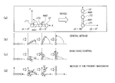
- FIG. 2 shows, by (a) to (d), diagrams illustrating a principle of a method of controlling the movement of an arm of a robot according to the embodiments, comparing with an example of conventional art;
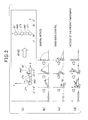
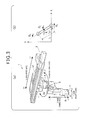
- FIG. 3 shows, by (a), a general schematic perspective view of a robot exemplified in a first embodiment of the present invention and, by (b), an X-Y plane on which physical parameters (dynamic parameters) of a robot are indicated;
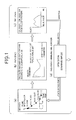
- FIG. 4 shows an electrical and functional block diagram illustrating a control system of the robot according to the first embodiment
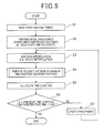
- FIG. 5 shows a flow diagram illustrating steps of generating a velocity pattern performed by a control unit, according to the steps shown in FIG. 1 ;
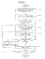
- FIG. 6 shows a flow diagram illustrating details of a part of the steps of generating the velocity pattern as shown in FIG. 5 , using the Bobrow's method and taking account of constraint conditions;
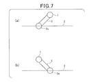
- FIG. 7 shows, by (a) and (b), a diagram illustrating a right-hand system and a left-hand system of a robot arm;
- FIG. 8 shows a diagram illustrating the reasons why a velocity pattern is calculated by converting coordinate positions of an end effector to an angle of each axis
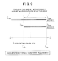
- FIG. 9 shows an explanatory diagram illustrating the constraint condition of path acceleration
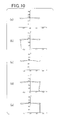
- FIG. 10 shows, by (a) to (e), a path in which coordinates of a first axis, a second axis and an end effector change on an X-Y plane;
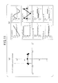
- FIG. 11 shows, by (a), a diagram concurrently plotting the five positions of the end effector, which are shown by (a) to (e) of FIG. 10 and, FIG. 11 shows, by (b), a diagram illustrating changes in an angle, angular velocity, angular acceleration and torque of each of the first and second axes during a movement from a start point to an end point;
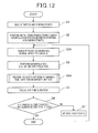
- FIG. 12 shows a flow diagram illustrating a process of preparing a velocity pattern, which is performed by a control unit, according to a second embodiment of the present invention
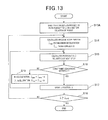
- FIG. 13 shows a flow diagram illustrating a detailed process of preparing a velocity pattern according to the Bobrow's method, taking account of constraint conditions, the process being performed as a part of the process shown in FIG. 12 ;
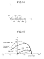
- FIG. 14 shows a schematic diagram illustrating a triaxial arm robot according to a modification
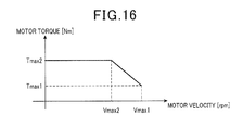
- FIG. 15 shows a diagram illustrating a simulation when the method of generating a path of the present invention is applied to the triaxial robot
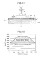
- FIG. 16 shows a diagram illustrating a TN curve of a motor used in a multiaxial robot, according to another modification
- FIG. 17 shows a schematic diagram illustrating a biaxial XR robot, according to still another modification.
- FIG. 18 shows a schematic diagram illustrating the effects of the method of generating a path of the present invention in the XR robot.
- FIGS. 1 to 11 hereinafter are described a method of generating a path (or trajectory) of a multiaxial robot and a control apparatus for the multiaxial robot, according to a first embodiment of the present invention.
- FIGS. 1 and 2 Before specifically describing an example of the multiaxial robot, referring to FIGS. 1 and 2 , an outline of a control method of the multiaxial robot of the present embodiment is described. First, referring to (a) to (d) of FIG. 2 , the control method of the present embodiment is described comparing with a control method based on conventional art.
- the simplest method in this case is to rotate only the first arm AM1 (i.e. the first axis J1) by 90° without moving the second arm AM2 (i.e. the second axis J2).
- the first arm AM1 greatly suffers from disproportionately imposed large load because only the first arm AM1 is moved.
- the arm as a whole has a constantly maximum movement radius that causes large inertia. Therefore, this raises a problem of allowing the movement velocity to be low.
- FIG. 2( c ) shows a movement based on the bang-bang control mentioned above.
- the arm is folded involving the movement of the second arm AM2 in addition to the movement of the first arm AM1. Accordingly, the inertia is reduced to enable high-velocity movement.
- no constraint conditions such as a velocity constraint imposed on the robot, are taken into account in this case. Therefore, it is impossible to actually move the robot in this way for the reduction of the time duration.
- the movement path as schematically shown in FIG. 2( d ) is realized. Specifically, when the movement of the end effector EF is started, the first arm AM1 (first axis J1) is rotated, first, in a direction of an end point (refer to the arrow A), while the second arm AM2 (second axis J2) is rotated in a direction opposite to the end point (refer to the arrow A′).
- the configuration of the arm is based on a so-called left-hand system.
- the second arm AM2 is permitted to pendulate in its rotational direction (refer to the arrow B′), so that, as viewed with reference to the first arm AM1, the end effector EF (the position of an end of the second arm AM2) approaches the end point preceding an end of the first arm AM1.
- the configuration of the arm is based on a so-called right-hand system.
- the second arm AM2 and the end effector EF are always positioned on the radius of a circle centering on the first arm AM1.
- the second arm AM2 is firstly rotated in a direction of a start point (the arrow A′) to allow a delay in the movement of the end effector EF.
- the second arm AM2 is rotated toward the end point, preceding the first arm AM1.
- the end effector EF precedes the first arm AM1.
- the coactive movement of the two arms AM1 and AM2 can disperse the load imposed on the motors of the two joints JT1 and JT2, compared to the movement shown in FIG. 2( b ). Further, since the arm is slightly folded, the inertia becomes smaller to thereby reduce the load imposed on the motors.
- the movement of the second arm AM2 causes a force accompanying the reaction in the first arm AM1, i.e. the first axis J1.
- a bias force is applied to the first arm AM1, as shown by the arrow A′′, accompanying the reaction against the temporarily reverse rotation (the arrow A′) of the second arm AM2.
- the bias force A′′ is applied in a direction of enhancing the rotation of the arm AM1 toward the end point.
- a suppressive force is applied to the first arm AM1, as shown by the arrow B′′, accompanying the reaction against the preceding movement (the arrow B′) in the rotational direction of the second arm AM2 up to then.
- the suppressive force B′′ is applied in a direction of suppressing the rotation (the arrow A) of the first arm AM1 up to then.
- the reaction forces i.e. the bias force or the suppressive force
- FIG. 1 illustrates diagrams schematically showing steps of realizing the movement path shown in FIG. 2( d ).
- a plurality of pass points are temporarily set while the end effector EF of the robot is moved from the start point to the end point ( FIG. 1( a )).
- the Bobrow's method is used to calculate a path of the end effector EF.
- a velocity pattern is calculated, which can realize a maximum velocity in the movement of the end effector EF via the pass points ( FIG. 1( b )).
- an equation corresponding to the actual motion of the robot this equation is hereinafter referred to as a motion equation
- a maximum velocity pattern is calculated upon satisfaction of the constraint conditions of the robot, the constraint conditions including the limitation in the movement velocity and torque of each axis.
- a time duration is calculated, which will be required for the robot to move from a predetermined start point to a predetermined end point according to the velocity pattern ( FIG. 1( c )). Then, updating the pass points ( FIG. 1( d )), the steps described above are repeatedly performed.
- the time duration is determined to have been converged to minimum, the series of steps is ended. The series of steps is performed for each axis of the multiaxial robot. The resultant path will be the one that satisfies the constraint conditions of the robot (i.e. the upper limits of velocity and torque at each of the joints of the robot) and enables the end effector EF to move from the start point to the end point in a shortest time.
- the information regarding the velocity pattern of each axis (i.e. path information) obtained in this way is stored in a storage (not shown) in a robot controller RC (refer to FIG. 4) , for use in the actual control of the multiaxial robot.
- the robot controller RC thus functions as a controlling apparatus for the robot.
- FIG. 3( a ) is a schematic diagram generally illustrating a four-axis robot 1 (multiaxial robot).
- the robot 1 includes a linear movement rail 2 .
- the linear movement rail 2 supports, via its lower surface, a movable body 2 a (base-side arm), as a first link, such that the movable body 2 a can linearly move along an X direction that is the first axis (X axis).
- the linear movement rail 2 includes a drive mechanism that can freely move the movable body 2 a .
- the drive mechanism is composed of a linear movement motor 3 arranged at an end of the linear movement rail 2 and a ball-screw mechanism, not shown.
- the movable body 2 a has a lower surface portion which is connected with an arm support base 4 .
- the arm support base 4 has a lower surface on which a horizontal turn arm 5 (end effector-side arm) extending in the horizontal direction is mounted.
- the horizontal turn arm 5 as a second link, has an end portion on a base-end side, through which the arm 5 is mounted to the lower surface of the arm support base 4 so that the arm 5 can turn in an R direction about a second axis (vertical axis, R axis).
- the horizontal turn arm 5 has the other end portion (end face) on a side opposite to the base-end side with respect to the vertical axis.
- the end face of the arm 5 is mounted with an elevating body 6 , as a third link, which is vertically movable (third axis, Z axis).
- the elevating body 6 has a lower surface on which a wrist 7 , as a fourth link, is mounted so as to be coaxially rotatable about a vertical axis (fourth axis, T axis).
- the wrist 7 is configured such that a work tool, such as a chuck (hand) for holding a work, is detachably attached thereto.
- the horizontal turn arm 5 is infinitely rotatable (turnable) in a horizontal direction by an arm rotating motor 8 (see FIG. 4 ) and a rotation transmission mechanism.
- the arm rotating motor 8 is arranged inside the arm support base 4 to serve as a drive source.
- the elevating body 6 is vertically moved at an end of the horizontal turn arm 5 by a motor and a rack-pinion mechanism incorporated in the horizontal turn arm 5 .
- the wrist 7 is coaxially rotated by a motor incorporated in the elevating body 6 .
- the movements of the robot 1 are ensured to be controlled, as shown in FIG. 4 , by a control unit 9 (control apparatus) of a robot controller RC on the basis such as of a work process program.
- the control unit 9 includes a CPU, ROM and RAM and connected with a teaching pendant 10 .
- the teaching pendant 10 includes a group of switches 11 and a display 12 as an indicating means.
- FIG. 3( b ) illustrates an X-Y plane on which physical parameters (dynamic parameters) of the robot 1 are indicated.
- the Y axis is orthogonal to the X axis.
- the front side of the robot 1 shown in FIG. 3( a ) corresponds to the positive side of the coordinate.
- references m 1 , m 2 and m 3 indicate a mass of the first link [kg], a mass of the second link [kg] and a total mass [kg] of “the third and fourth links and the loads”, respectively.
- References I g2 indicates a distance [m] from the axis position of the first link to the gravity center of the second link.
- Reference I 2 indicates a length [m] of the second link.
- Reference I 2 indicates an inertia [kgm 2 ] around the gravity center of the second link.
- Reference I 4 indicates an inertia [kgm 2 ] around the third and fourth links and a total gravity center.
- Reference ⁇ 1 indicates a joint position of the first axis, and reference ⁇ 2 indicates a joint angle of the second axis.
- the multiaxial robot 1 described above has four axes.
- the method of generating a path and the control method according to the present embodiment can be performed with respect a plurality of axes, i.e. two or three axes or more, among the four axes.
- axes i.e. two or three axes or more
- only the first and second axes are subjected to calculation in the following description.
- path generation involving three or more axes and control will be described later.
- ⁇ ′ Velocity of a robot shown by an angular velocity of each axial joint [rad/s]:
- ⁇ Each position on a path, which is referred to as a path parameter:
- ⁇ ′ Gradient at each position on a path, which is referred to as a path velocity:
- ⁇ ′′ Curvature at each position on a path, which is preferred to as a path acceleration.
- ⁇ represents a torque vector.
- the physical parameters of the robot 1 are reflected to an inertia matrix H and a matrix h indicating the centrifugal and Coriolis forces, in Formula (1).
- FIG. 5 is a flow diagram illustrating the steps corresponding to those which are illustrated in FIG. 1 , performed by the control unit 9 .
- the control unit 9 reads a start point and an end point of the end effector of the robot 1 (step S 1 ).
- the start and end points are given, for example, as teaching points by the operator.
- the control unit 9 determines three points between the start and end points, for use as initial pass points (interpolating points) (step S 2 ).
- initial pass points linear interpolation or the like is used. For example, when the coordinate of the start point is (0, 0) and the coordinate of the end point is (30, 100), the initial pass points are determined to be (7.5, 25), (15, 50) and (22.5, 75).
- control unit 9 performs a spline interpolation, for example, to interpolate between the start point, the end point and the three initial pass points (step S 3 ). With respect to the path resulting from the spline interpolation, the control unit 9 prepares a velocity pattern that minimizes the time duration, using the Bobrow's method (step S 4 ).
- control unit 9 calculates a time duration in the case where the end effector (the end of the second axis, i.e. the second arm in the present example) of the robot 1 is moved along the interpolated path, according to the prepared velocity pattern (step S 5 ). Then, the control unit 9 calculates the difference between the time duration with the time duration calculated previously. Then, the control unit 9 determines whether or not the difference between the two time durations is smaller than a predetermined threshold (e.g., 0.001 s) (step S 6 ). If a negative determination is made (NO at step S 6 ), the pass points calculated at step S 2 are updated using a downward simplex method or the like (step S 7 ). As a matter of course, other method, e.g., gradient method or genetic algorithm, may be used here.
- a predetermined threshold e.g., 0.001 s
- step S 3 After updating the pass points, the process of the control unit 9 returns to step S 3 , and step S 3 and the subsequent steps up to step S 7 are repeatedly performed. Then, if the difference in the time duration between this time and the previous time is less than the predetermined threshold (YES at step S 6 ), the series of steps of calculating a movement path is ended.
- the end effector position x is converted to an angle q of each axis (arm) (step S 12 ).
- q p ⁇ 1 ( f ( ⁇ )) (4)
- p represents a function that indicates forward kinematics.
- the reason why the end effector position x is converted to an angle q is that a path of the end effector can be calculated without limiting the hand system, i.e. the configuration of the arm of the robot 1 ( FIG. 7( a ) shows a left-hand system and FIG. 7( b ) shows a right-hand system).
- a movement path is calculated by converting, in advance, the coordinate positions into the angles of the individual axes. Accordingly, in the event the configuration of the arm is changed at some point of the path, the constraint conditions will not be discontinuous and thus the results of the calculation can be obtained. In this way, a velocity pattern that can achieve a maximum velocity is calculated without being constrained by the configuration of the arm.
- the control unit 9 calculates a maximum acceleration ⁇ ′′ max and a maximum deceleration ⁇ ′′ min from Formula (5) (regarding this, refer to Formulas (8) to (10) of Document 1).
- the symbol ′′ suffixed to ⁇ replaces the double dots that indicate acceleration in Document 1.
- the maximum acceleration ⁇ ′′ max and the maximum deceleration ⁇ ′′ min calculated here are the constraint conditions associated with the acceleration in the movement of the robot 1 .
- control unit 9 calculates a next position ⁇ and a velocity ⁇ ′ from Formulas (11) and (12), using the maximum acceleration ⁇ ′′ max (or the maximum deceleration ⁇ ′′ min ) (step S 15 ).
- time t is a sampling time (e.g., 1 ms).
- symbols ⁇ 0 and ⁇ ′ 0 indicate a current position and velocity, respectively.
- the symbol ′ suffixed to ⁇ indicates a first-order differentiation and replaces the dot that indicates velocity in Document 1.
- ⁇ 0.5 ⁇ ′′ max t 2 + ⁇ ′t (11)
- ⁇ ′ ⁇ ′′ max t (12)
- control unit 9 determines whether or not the velocity ⁇ ′ and the acceleration (deceleration) ⁇ ′′ of the path parameter ⁇ satisfy the constraint conditions (step S 16 ). Specifically, the control unit 9 determines whether or not both of the following conditions: ⁇ ′ min ⁇ ′ ⁇ ′ max (13) ⁇ ′′ min ( ⁇ , ⁇ ′) ⁇ ′′ ⁇ ′′ max ( ⁇ , ⁇ ′) (14) are concurrently satisfied. Depending on whether the robot is in acceleration or deceleration, ⁇ ′ min or ⁇ ′ max and ⁇ ′′ min or ⁇ ′′ max is used.
- FIG. 9 is a schematic diagram based on FIG. 2 of Document (2) set forth above. Specifically, FIG. 9 shows a range of satisfying the constraint conditions regarding the acceleration (deceleration) ⁇ ′′ of the path parameter ⁇ of a biaxial robot. More specifically, an allowable range ⁇ ′′ min to ⁇ ′′ max is set under AND conditions within a range of a maximum acceleration to a maximum deceleration specified to each axis (motor arranged at each joint).
- the velocity condition and the acceleration (torque) condition are minimum conditions necessary as the constraint conditions. Depending on the situation, other conditions may be added.
- step S 16 if the velocity ⁇ ′ and the acceleration (deceleration) ⁇ ′′ of the path parameter ⁇ satisfy both of the constraint conditions of Formulas (13) and (14) (YES at step S 16 ), the control unit 9 updates the position ⁇ to the value calculated at step S 15 (step S 17 ). Then, the control unit 9 determines whether or not the position ⁇ has reached an end ⁇ end (step S 18 ). If a negative determination is made (NO at step S 18 ), the process returns to step S 14 . If an affirmative determination is made (YES at step S 18 ), the process is ended.
- step S 16 if the velocity ⁇ ′ and the acceleration (deceleration) ⁇ ′′ do not satisfy at least one of the constraint conditions of Formulas (13) and (14) (NO at step S 16 ), the control unit 9 performs step S 19 . Specifically, when the robot is in a state of acceleration, the control unit 9 subtracts an arbitrary constant “a” from the maximum acceleration ⁇ ′′ max to use the resultant value as a new maximum acceleration ⁇ ′′ max . On the other hand, when the robot is in a state of deceleration, the control unit 9 subtracts the arbitrary constant “a” from the maximum deceleration ⁇ ′′ min to use the resultant value as a new maximum deceleration ⁇ ′′ min . After that, the process returns to step S 15 where the position ⁇ and the velocity ⁇ ′, i.e. the path parameters, are recalculated.
- a velocity pattern that can achieve a maximum movement velocity is obtained.
- the constraint conditions of the robot 1 can be satisfied.
- the time duration according to steps S 4 and S 5 is calculated for forward and backward velocity patterns between the start and end points. That is, the algorithm set forth in step S 4 is applied to calculation of the forward velocity pattern from the start point to the end point, and then applied to calculation of the backward velocity pattern from the end point to the start point. After that, the forward velocity pattern and the backward velocity pattern are combined, and a time duration is calculated for the combined pattern.
- FIGS. 10 and 11 show an example of a path calculated as described above for the minimization of the movement velocity of the end effector of the robot 1 .
- FIG. 10( a ) is a diagram illustrating, with the solid line, a path, i.e. changes in coordinates, on the X-Y plane, of the first and second axes and the end effector. As shown in the figure, the coordinate at the start point is ( ⁇ 0.3, 0.3) and the coordinate at the end point is (0.3, 0.3).
- FIG. 11( b ) is a diagram illustrating changes in the angle, angular velocity, angular acceleration and torque of the first and second axes during the movement from the start point to the end point.
- the first axis linearly moves on the X axis from ⁇ 0.3 [m] (see FIG. 10( a )) to 0.3 [m] (see FIG. 10( e )). This corresponds to the movement of the movable body 2 a along the linear movement rail 2 .
- the second axis has a rotation angle ⁇ 2 (rotation angle of the horizontal turn arm 5 ) which is 0 [rad] at the start and end points and at a midpoint on the X axis.
- ⁇ 2 rotation angle of the horizontal turn arm 5
- the X-axis coordinate of the end effector is on a negative side with respect to the coordinate of the movable body 2 a .
- This state corresponds to the right-hand system in light of the configuration of the arm of the robot 1 .
- the second axis is in a state of being rotated, by ⁇ 0.6 [rad], in the direction of the start point.
- the X-axis of the position of the end effector is on a positive side with respect to the coordinate of the movable body 2 a .
- This state corresponds to the left-hand system in light of the configuration of the arm of the robot 1 .
- the angular velocity of the second axis reaches a positive-side peak (10 rad/s, peak V2) right after moving away from the start point (V1). Then, from this peak point, the angular velocity linearly changes toward a negative-side peak ( ⁇ 10 rad/s, peak V3) at a midpoint. Further, the angular velocity also linearly changes from the midpoint toward a positive-side peak (10 rad/s, peak V4) right before the end point. In other words, as shown in FIG. 11( b ), a symmetrical velocity pattern is drawn centering on the midpoint.
- the angular acceleration corresponding to the above angular velocity pattern will have a pattern as follows. Specifically, the angular acceleration reaches a positive-side peak 400 rad/s 2 from 0 at the start point V1, turns to a negative value of about ⁇ 50 rad/s 2 at the peak V2 and keeps the negative value of about ⁇ 50 rad/s 2 up to the peak V3 at the midpoint. Further, when the angular acceleration turns to a positive value of 50 rad/s 2 at the peak V3 at the midpoint, the value is kept up to the peak V4. Then, the angular acceleration reaches a negative-side peak ⁇ 400 rad/s 2 at the peak V4 and returns to 0 at the end point V5.
- the movement of the second axis as described above exerts the following effects. Specifically, upon start of the movement from the start point, the second axis changes its angle ⁇ 2 from 0 [rad] ⁇ 0.6 [rad] ⁇ 0 [rad] before it reaches the midpoint on the X axis. Thus, the end effector of the robot 1 , which has once pendulated in a positive-rotation direction, pendulates back in a negative-rotation direction. In response, a reaction accompanying this movement is caused in the movable body 2 a to generate an acceleration force for accelerating the movement of the first arm when movement is started. This bias force assists (biases) the movement of the first and second arms in the direction of the end point.
- the second axis changes its angle ⁇ 2 from 0 [rad] ⁇ 0.6 [rad] ⁇ 0 [rad] before it reaches the end point from the midpoint on the X axis.
- the end effector of the robot 1 which has once pendulated in a negative-rotation direction, pendulates back in a positive-rotation direction.
- a reaction accompanying the movement is caused in the movable body 2 a to work as a deceleration force.
- the deceleration force assists (suppresses) the deceleration movement of the second axis before it reaches the end point and stops its movement.
- the broken lines in FIG. 10 indicate a path in the case where the first axis is moved without rotating the second axis at all.
- the time duration was 536 ms
- a simulation based on the path indicated by the solid line resulted in a time duration of 514 ms.
- the solid-line path had an effect of reducing the time duration by 4% or more.
- the robot 1 when the robot 1 is allowed to have a time duration equal to that of the conventional art, the robot 1 can be moved with less energy than in the conventional art, thereby contributing to energy saving. Further, for example, reducing the output of the motors, the level of wattage of the motors can be reduced, leading to reduction in the size and cost of the robot 1 .
- FIG. 11( a ) is a diagram concurrently plotting the five positions of the end effector illustrated in (a) to (e) of FIG. 10 . These five positions correspond to the five points (V1 to V5) plotted on the angular velocity pattern of the second axis shown in FIG. 11( b ), i.e. correspond to reverse points of the angular velocity or the angular acceleration.
- step S 2 of FIG. 5 three initial pass points are set between the start and end points. These three initial pass points are selected so as to correspond to the reverse points of the angular velocity or the angular acceleration shown in FIG. 11 . This is because selection of the three initial pass points in this manner is regarded to be advantageous in enhancing the efficiency of calculation.
- the number of the initial pass points is set to three, taking account of the balance between reduction of the time duration and suppression in the increase of the calculation time. Selection of the initial pass points is not required to be strictly performed. As described above, the three initial points may be determined such as by simply dividing the linear distance between the start and end points into four. In the course of repeating the steps shown in FIG. 1 or 5 , a new path is calculated with the update of the pass points to achieve optimization.
- a path will be selected, which would minimize the time duration in a movement pattern such as a pick-and-place pattern.
- the selection of such a path depends on the coordinate positions of the three pass points as the three reverse points, as shown in FIG. 11( a ), of the angular velocity or the angular acceleration of the second axis. In this way, when the number of the initial pass points is set to three, a path that minimizes the time duration can be calculated, while suppressing increase in the calculation time.
- the object to be moved is the multiaxial robot 1 that includes the movable body 2 a positioned on the base side and the horizontal turn arm 5 connected thereto on the end-effector side of the movable body 2 a .
- the control unit 9 generates a path such that, in moving the end effector from the start point, the reaction caused in the movable body 2 a by the movement of the horizontal turn arm 5 can increase the acceleration force, which is caused by the movement of the movable body 2 a along its base axis that is the linear movement rail 2 .
- control unit 9 generates the path such that, in stopping the end effector at the end point, the reaction caused in the movable body 2 a by the movement of the horizontal turn arm 5 can increase the deceleration force caused by the movement of the movable body 2 a.
- the horizontal turn arm 5 moves such that it causes a reaction to the movable body 2 a .
- the path can increase both the acceleration force required in activating the end effector and the deceleration force required in stopping the end effector.
- the velocity of moving the end effector from the start point to the end point is enhanced to thereby reduce the time duration of the end effector.
- the horizontal turn arm 5 is slightly rotated to reduce the inertia caused in the linear movement of the movable body 2 a . Accordingly, the end effector can be moved with less energy. Therefore, when the robot 1 is moved in a time duration equal to that of a path based on a conventional method, the robot 1 can be moved consuming less energy than in the conventional art.
- the path described above is generated as a result of the calculation based on the motion dynamics of the multiaxial robot 1 . Accordingly, a path calculated in this manner can maximize the movement velocity within a range of satisfying the constraint conditions of the robot. Thus, an optimized path for practical use can be generated.
- positions on the path are converted to angles. Accordingly, the configuration of the arm of the robot 1 is not limited to either of the left-hand system and the right-hand system. Thus, a velocity pattern that can achieve a maximum velocity is calculated using both of the left- and right-hand systems.
- the movable body 2 a is moved in the direction of the end point, while the horizontal turn arm 5 is rotated so that an end thereof moves in a direction opposite to the direction of the end point. After that, the end of the horizontal turn arm 5 is rotated in the direction of the end point. In this case, the reaction caused by the movement of the horizontal turn arm 5 comes to assist the acceleration force at the time of activating the robot 1 .
- the path is generated such that, in stopping the end effector at the end point, the horizontal turn arm 5 at a position where the end thereof, or the end effector, goes beyond the end point is moved therefrom toward the start point.
- the path is generated so that the end of the horizontal turn arm 5 , or the end effector, is permitted to pendulate back toward the start point and stopped.
- the reaction caused by the movement of the horizontal turn arm 5 comes to assist the deceleration force at the time of stopping the robot 1 .
- the path generated in this way allows the horizontal turn arm 5 to move such that it causes a reaction to the movable body 2 a.
- Three pass points are set between the start and end points and a time duration suitable for the pass points is ensured to be calculated, while the positions of the three pass points are changed. Specifically, in order to generate a path that minimizes the time duration of the end effector, the path is required to be optimized. In order to optimize the path, one or more pass points are required to be set between the start and end points, and the movement velocity calculated when the positions of the pass points are changed is required to be compared with the movement velocity before the change.
- the movable body 2 a that is an axis on the base side with respect to the horizontal turn arm 5 will have: a time point when an acceleration is given thereto right after the activation; a time point when the direction of the acceleration is reversed at some point of the movement; and a time point when the acceleration is rendered to be zero right before the stop.
- it is considered to be important to optimize at least the pass points corresponding to the above three time points. Accordingly, when the pass points corresponding to the above three time points are set, a path that minimizes the time duration is efficiently generated while the amount of calculation is suppressed. In this way, an optimized and practically usable path can be obtained.
- the potential of the motors or the actuators can be maximally drawn out, which would not have been achieved by the method based on conventional art due to the limitation of the method.
- FIGS. 12 and 13 hereinafter is described a second embodiment related to a method of generating a path of a multiaxial robot and a control apparatus for the multiaxial robot.
- the position x of the end effector is converted to the angle q of each axis by solving the inverse kinematics (refer to step S 12 ).
- conversion to the angle q is performed at a stage prior to the preparation of a shortest velocity pattern, that is, at the stage of interpolating pass points.
- steps other than the above are similar to those of the first embodiment.
- This can eliminate the process of solving the equation of the inverse kinematics mentioned above, i.e. steps S 11 and S 12 of FIG. 6 described above.
- the motion dynamics forward kinematics only has to be solved in a joint angle space, leading to reduction of the load of calculation accordingly.
- the number of the pass points may be four or more.
- a method other than the Bobrow's method may be used in calculating a path of maximizing the velocity of the multiaxial robot, on the basis of the motion dynamics of the robot.
- the base-side arm and the end effector-side arm are determined on the basis of the positional relationship of the arms.
- a multiaxial robot may have a third arm connected to an end of a second arm.
- the first arm is referred to as a “base-side arm”
- the second and the third arms are referred to as “end effector-side arms”.
- the second arm is referred to as a “base-side arm”
- the third arm is referred to as an “end effector-side arm”.
- FIG. 14 shows a triaxial robot arm.
- This triaxial arm has arms AM1, AM2 and AM3 which are connected to joints JT1, JT2 and JT3, respectively.
- the method of generating a path and the control method described in the first or second embodiment can be similarly applied.
- the triaxial robot arm was activated as indicated in an example shown in FIG. 15 .
- the triaxial robot arm was activated as indicated in an example shown in FIG. 15 .
- the positions of the three axes (J1, J2 and J3) from a start point of (0, 0, 0) degree to an end point of (90, 45, 90) degree, an effect of enhancing the acceleration force and the deceleration force was confirmed to be obtained by the reaction of the end effector-side arm.
- the time duration was confirmed to be shortened.
- the application of the present invention is not limited to a multiaxial robot that includes a travelling axis which is combined with a rotation axis. Instead, the present invention may be applied to a multiaxial robot having a different combination of axes.
- the upper limits ⁇ ′ min and ⁇ ′ max of the velocity of the constraint conditions are treated as being constant. However, these values may be variable values. Two examples of this are provided herein.
- FIG. 16 is a diagram illustrating a TN curve of a generally known motor. It is known that, as a motor increases its velocity, the outputted maximum torque decreases. Therefore, in this example, the constraint condition of the motor related to torque is expressed as follows, considering the above relationship: ⁇ ′′ min ( ⁇ , q′/f ) ⁇ ′′( ⁇ , q′f ) ⁇ ′′ max ( ⁇ , q′/f ) (20)
- a maximum torque corresponding to the current velocity q′ is calculated to make a determination based on Formula (20).
- maximum torque is varied according to velocity.
- the second example relates to a function of varying an upper-limit velocity as one of the constraint conditions in an XR robot that has a travelling axis such as of a ball screw.
- the XR robot shown in FIG. 17 includes a ball screw 20 , a direct-acting axis J1 (X axis), a movable stage 23 and an arm 25 .
- the direct-acting axis J1 has ends which are fixed to a fixed base 22 via a fixing means 21 .
- the movable stage 23 is movably held by the direct-acting axis J1.
- the arm 25 is rotatably held by the movable stage 23 via a joint 24 .
- the arm 25 serves as an axis of rotation (R axis) J2.
- the biaxial XR robot is configured in this way. In the generation of the path of the two axes J1 and J2, the configuration according to the present invention is implemented to thereby enhance the acceleration force and the deceleration force.
- the upper-limit velocity In a single axis such as of a ball screw, its upper-limit velocity (so-called limit velocity or critical velocity) is set up.
- the value of the upper-limit velocity however varies depending on the position of the axis from its fixed ends.
- the top edge (upper-limit velocity) of the trapezoid has been set to a constant value that is a value considering the safety factor.
- the method of generating a path according to the present invention can be applied to the XR robot to change the upper-limit velocity according to a position P of the movable stage 23 along the direct-acting axis J1.
- the constraint condition ⁇ ′ min ⁇ ′ ⁇ ′ max of velocity is determined by the position ⁇ (i.e. angle) and the maximum velocity q′. Therefore, the upper-limit velocity can be varied according to the position P on the axis J1.
- the velocity area that has not been fully used in the conventional art can be efficiently used to further shorten the time duration.
Landscapes
- Engineering & Computer Science (AREA)
- Robotics (AREA)
- Mechanical Engineering (AREA)
- Human Computer Interaction (AREA)
- Manufacturing & Machinery (AREA)
- Physics & Mathematics (AREA)
- General Physics & Mathematics (AREA)
- Automation & Control Theory (AREA)
- Manipulator (AREA)
- Numerical Control (AREA)
Priority Applications (3)
| Application Number | Priority Date | Filing Date | Title |
|---|---|---|---|
| US13/852,337 US9242376B2 (en) | 2013-03-28 | 2013-03-28 | Method of generating path of multiaxial robot and control apparatus for the multiaxial robot |
| JP2013181242A JP6167770B2 (ja) | 2013-03-28 | 2013-09-02 | 多軸型ロボットの軌道生成方法及び多軸型ロボットの制御装置 |
| DE102014104220.4A DE102014104220B9 (de) | 2013-03-28 | 2014-03-26 | Verfahren zum Steuern des Antriebs eines mehrachsigen Roboters und Steuervorrichtung für den mehrachsigen Roboter |
Applications Claiming Priority (1)
| Application Number | Priority Date | Filing Date | Title |
|---|---|---|---|
| US13/852,337 US9242376B2 (en) | 2013-03-28 | 2013-03-28 | Method of generating path of multiaxial robot and control apparatus for the multiaxial robot |
Publications (2)
| Publication Number | Publication Date |
|---|---|
| US20140297030A1 US20140297030A1 (en) | 2014-10-02 |
| US9242376B2 true US9242376B2 (en) | 2016-01-26 |
Family
ID=51519979
Family Applications (1)
| Application Number | Title | Priority Date | Filing Date |
|---|---|---|---|
| US13/852,337 Active 2033-08-27 US9242376B2 (en) | 2013-03-28 | 2013-03-28 | Method of generating path of multiaxial robot and control apparatus for the multiaxial robot |
Country Status (3)
| Country | Link |
|---|---|
| US (1) | US9242376B2 (de) |
| JP (1) | JP6167770B2 (de) |
| DE (1) | DE102014104220B9 (de) |
Cited By (4)
| Publication number | Priority date | Publication date | Assignee | Title |
|---|---|---|---|---|
| US9925662B1 (en) * | 2015-06-28 | 2018-03-27 | X Development Llc | Generating a trained robot path based on physical manipulation of the robot and based on training user interface input(s) associated with the physical manipulation |
| US10207404B2 (en) * | 2017-02-09 | 2019-02-19 | X Development Llc | Generating a robot control policy from demonstrations collected via kinesthetic teaching of a robot |
| US20200189099A1 (en) * | 2017-09-15 | 2020-06-18 | Google Llc | Improvements related to generating a robot control policy from demonstrations collected via kinesthetic teaching of a robot |
| US20210260760A1 (en) * | 2018-06-19 | 2021-08-26 | Kuka Deutschland Gmbh | Method and system for transferring an end effector of a robot between one end effector pose and a further end effector pose |
Families Citing this family (20)
| Publication number | Priority date | Publication date | Assignee | Title |
|---|---|---|---|---|
| JP6123595B2 (ja) * | 2013-09-10 | 2017-05-10 | 株式会社デンソーウェーブ | 2軸ロボットの速度制御方法 |
| JP6455019B2 (ja) * | 2014-08-21 | 2019-01-23 | 株式会社デンソーウェーブ | ロボットの制御装置及び制御方法 |
| EP3272473B1 (de) * | 2015-03-20 | 2022-09-14 | FUJI Corporation | Lehrvorrichtung und verfahren zur erzeugung von kontrollinformationen |
| DE102015106227B3 (de) * | 2015-04-22 | 2016-05-19 | Deutsches Zentrum für Luft- und Raumfahrt e.V. | Steuern und/oder Regeln von Motoren eines Roboters |
| JP6339534B2 (ja) * | 2015-07-17 | 2018-06-06 | ファナック株式会社 | 最大で二つのワークを把持するハンドを備えたロボットの制御方法およびロボット制御装置 |
| JP6601155B2 (ja) * | 2015-10-28 | 2019-11-06 | 株式会社デンソーウェーブ | ロボット制御システム |
| CN109328124A (zh) * | 2016-04-21 | 2019-02-12 | 休恩登·杰拉德·托马斯 | 执行操作的机器人系统 |
| US9981381B1 (en) * | 2016-06-08 | 2018-05-29 | X Development Llc | Real time generation of phase synchronized trajectories |
| JP6844434B2 (ja) * | 2017-06-15 | 2021-03-17 | 株式会社デンソーウェーブ | ロボットの負荷重心位置推定装置及びロボットの負荷重心位置推定方法 |
| CN107450431B (zh) * | 2017-08-14 | 2020-04-10 | 广州耐奇电气科技有限公司 | 一种能源综合管理系统 |
| JP2019126850A (ja) * | 2018-01-22 | 2019-08-01 | ファナック株式会社 | ロボットの制御方法および制御装置 |
| US11458626B2 (en) * | 2018-02-05 | 2022-10-04 | Canon Kabushiki Kaisha | Trajectory generating method, and trajectory generating apparatus |
| JP7225560B2 (ja) * | 2018-04-26 | 2023-02-21 | セイコーエプソン株式会社 | 制御装置、ロボットシステム、及び表示制御方法 |
| US11998296B2 (en) * | 2018-07-30 | 2024-06-04 | Intuitive Surgical Operations, Inc. | Hard stop protection system and method |
| WO2020066297A1 (ja) * | 2018-09-26 | 2020-04-02 | 株式会社Ihi | 加速度導出装置及び方法 |
| JP7028196B2 (ja) | 2019-01-15 | 2022-03-02 | オムロン株式会社 | ロボット制御装置、ロボット制御方法、及びロボット制御プログラム |
| GB2588629B (en) * | 2019-10-29 | 2024-01-03 | Cmr Surgical Ltd | Robotic joint control |
| CN111775148B (zh) * | 2020-06-15 | 2022-03-08 | 珠海格力电器股份有限公司 | 一种机器人控制方法、装置、存储介质及机器人 |
| WO2024154249A1 (ja) * | 2023-01-18 | 2024-07-25 | 株式会社Fuji | 軌道生成装置および軌道生成方法 |
| CN116197917B (zh) * | 2023-04-28 | 2023-08-01 | 苏州艾利特机器人有限公司 | 自适应最大加速度计算方法、装置、存储介质及电子设备 |
Citations (10)
| Publication number | Priority date | Publication date | Assignee | Title |
|---|---|---|---|---|
| US5294873A (en) * | 1992-10-27 | 1994-03-15 | The United States Of America As Represented By The Administrator Of The National Aeronautics And Space Administration | Kinematic functions for redundancy resolution using configuration control |
| US5811952A (en) | 1995-06-29 | 1998-09-22 | Fanuc Ltd. | Method of setting accelerating/decelerating motion of robot |
| JPH1153021A (ja) | 1997-08-05 | 1999-02-26 | Yaskawa Electric Corp | 産業用ロボットの加減速パターン生成方法 |
| JP2000094371A (ja) | 1998-09-18 | 2000-04-04 | Yaskawa Electric Corp | ロボットの最短時間制御装置 |
| US6216058B1 (en) * | 1999-05-28 | 2001-04-10 | Brooks Automation, Inc. | System of trajectory planning for robotic manipulators based on pre-defined time-optimum trajectory shapes |
| US20020045957A1 (en) | 2000-10-18 | 2002-04-18 | Fanuc Ltd. | Acceleration and deceleration control method |
| JP2002321178A (ja) | 2001-04-20 | 2002-11-05 | Yaskawa Electric Corp | ロボットの加減速時間決定方法 |
| US7039494B2 (en) | 2003-08-05 | 2006-05-02 | Fanuc Ltd | Controller for machine |
| US20100318224A1 (en) * | 2008-03-06 | 2010-12-16 | Akinobu Okuda | Manipulator and method of controlling the same |
| US20120029699A1 (en) * | 2010-06-04 | 2012-02-02 | Institute Of Automation, Chinese Academy Of Sciences | System and method for robot trajectory generation with continuous accelerations |
Family Cites Families (3)
| Publication number | Priority date | Publication date | Assignee | Title |
|---|---|---|---|---|
| JP2006198716A (ja) * | 2005-01-20 | 2006-08-03 | Amada Co Ltd | 回転制御方法およびその装置並びにそれを用いた板材加工機の板材位置決め方法および装置 |
| JP5076824B2 (ja) * | 2007-11-15 | 2012-11-21 | 株式会社デンソーウェーブ | 吊り型ロボット |
| JP4942672B2 (ja) * | 2008-01-25 | 2012-05-30 | 三菱電機株式会社 | ロボット軌道制御装置及びロボット軌道制御方法 |
-
2013
- 2013-03-28 US US13/852,337 patent/US9242376B2/en active Active
- 2013-09-02 JP JP2013181242A patent/JP6167770B2/ja active Active
-
2014
- 2014-03-26 DE DE102014104220.4A patent/DE102014104220B9/de active Active
Patent Citations (11)
| Publication number | Priority date | Publication date | Assignee | Title |
|---|---|---|---|---|
| US5294873A (en) * | 1992-10-27 | 1994-03-15 | The United States Of America As Represented By The Administrator Of The National Aeronautics And Space Administration | Kinematic functions for redundancy resolution using configuration control |
| US5811952A (en) | 1995-06-29 | 1998-09-22 | Fanuc Ltd. | Method of setting accelerating/decelerating motion of robot |
| JPH1153021A (ja) | 1997-08-05 | 1999-02-26 | Yaskawa Electric Corp | 産業用ロボットの加減速パターン生成方法 |
| JP2000094371A (ja) | 1998-09-18 | 2000-04-04 | Yaskawa Electric Corp | ロボットの最短時間制御装置 |
| US6216058B1 (en) * | 1999-05-28 | 2001-04-10 | Brooks Automation, Inc. | System of trajectory planning for robotic manipulators based on pre-defined time-optimum trajectory shapes |
| US20020045957A1 (en) | 2000-10-18 | 2002-04-18 | Fanuc Ltd. | Acceleration and deceleration control method |
| JP2002132349A (ja) | 2000-10-18 | 2002-05-10 | Fanuc Ltd | 加減速制御方法 |
| JP2002321178A (ja) | 2001-04-20 | 2002-11-05 | Yaskawa Electric Corp | ロボットの加減速時間決定方法 |
| US7039494B2 (en) | 2003-08-05 | 2006-05-02 | Fanuc Ltd | Controller for machine |
| US20100318224A1 (en) * | 2008-03-06 | 2010-12-16 | Akinobu Okuda | Manipulator and method of controlling the same |
| US20120029699A1 (en) * | 2010-06-04 | 2012-02-02 | Institute Of Automation, Chinese Academy Of Sciences | System and method for robot trajectory generation with continuous accelerations |
Non-Patent Citations (4)
| Title |
|---|
| Bobrow et al., "Time-Optimal Control of Robotic Manipulators Along Specified Paths," The International Journal of Robotics Research, vol. 4, No. 3, 1985, pp. 3-17. |
| Dec. 8, 2014 Office Action issued in German Application No. 102014104220.4. |
| James E. Bobrow, "Optimal Robot Path Planning Using the Minimum-Time Criterion," IEEE Journal of Robotics and Automation, vol. 4, No. 4, Aug. 1988, pp. 443-450. |
| Liu et al., "Time-Optimal Trajectory Generation of a Fast-Motion Planar Parallel Manipulator," Proceedings of the 2006 IEEE/RSJ International Conference on Intelligent Robots and Systems Oct. 9-15, 2006, Beijing, China, pp. 754-759. |
Cited By (9)
| Publication number | Priority date | Publication date | Assignee | Title |
|---|---|---|---|---|
| US9925662B1 (en) * | 2015-06-28 | 2018-03-27 | X Development Llc | Generating a trained robot path based on physical manipulation of the robot and based on training user interface input(s) associated with the physical manipulation |
| US10207404B2 (en) * | 2017-02-09 | 2019-02-19 | X Development Llc | Generating a robot control policy from demonstrations collected via kinesthetic teaching of a robot |
| US10391632B2 (en) | 2017-02-09 | 2019-08-27 | X Development Llc | Generating a robot control policy from demonstrations collected via kinesthetic teaching of a robot |
| US11554485B2 (en) | 2017-02-09 | 2023-01-17 | X Development Llc | Generating a robot control policy from demonstrations collected via kinesthetic teaching of a robot |
| US11872699B2 (en) | 2017-02-09 | 2024-01-16 | Google Llc | Generating a robot control policy from demonstrations collected via kinesthetic teaching of a robot |
| US20200189099A1 (en) * | 2017-09-15 | 2020-06-18 | Google Llc | Improvements related to generating a robot control policy from demonstrations collected via kinesthetic teaching of a robot |
| US11565412B2 (en) * | 2017-09-15 | 2023-01-31 | Google Llc | Generating a robot control policy from demonstrations collected via kinesthetic teaching of a robot |
| US20210260760A1 (en) * | 2018-06-19 | 2021-08-26 | Kuka Deutschland Gmbh | Method and system for transferring an end effector of a robot between one end effector pose and a further end effector pose |
| US12036677B2 (en) * | 2018-06-19 | 2024-07-16 | Kuka Deutschland Gmbh | Method and system for transferring an end effector of a robot between one end effector pose and a further end effector pose |
Also Published As
| Publication number | Publication date |
|---|---|
| DE102014104220B4 (de) | 2015-12-10 |
| DE102014104220B9 (de) | 2016-01-28 |
| US20140297030A1 (en) | 2014-10-02 |
| JP2014193519A (ja) | 2014-10-09 |
| JP6167770B2 (ja) | 2017-07-26 |
| DE102014104220A1 (de) | 2014-10-02 |
Similar Documents
| Publication | Publication Date | Title |
|---|---|---|
| US9242376B2 (en) | Method of generating path of multiaxial robot and control apparatus for the multiaxial robot | |
| US9221175B2 (en) | Method of generating path of multiaxial robot and control apparatus for the multiaxial robot | |
| US8600554B2 (en) | System and method for robot trajectory generation with continuous accelerations | |
| US20110224815A1 (en) | Industrial Robot And Path Planning Method For Controlling The Movement Of An Industrial Robot | |
| US7047107B2 (en) | Robot control apparatus | |
| JP5144035B2 (ja) | 産業用ロボットのツールの位置・姿勢制御方法及び制御システム | |
| JP6123595B2 (ja) | 2軸ロボットの速度制御方法 | |
| CN112703090B (zh) | 机器人控制装置、机器人控制方法及存储介质 | |
| JP6057284B2 (ja) | 多関節ロボット及び半導体ウェハ搬送装置 | |
| JP2013223895A (ja) | ロボット制御方法及びロボット制御装置 | |
| JP4970492B2 (ja) | 多関節ロボット | |
| YAMAKAWA | Brachiation motion by a 2-DOF brachiating robot with hook-shaped end effectors | |
| JP2007316862A (ja) | サーボドライバおよび複数軸のサーボシステム | |
| Mettin et al. | Analysis of human-operated motions and trajectory replanning for kinematically redundant manipulators | |
| JP4647919B2 (ja) | 制御方法および制御装置 | |
| JPS62154006A (ja) | ロボツト制御装置 | |
| US20230286152A1 (en) | Robot system and controller | |
| JP6057283B2 (ja) | 多関節ロボット及び半導体ウェハ搬送装置 | |
| JP3194829B2 (ja) | ロボットの動作プログラム生成装置 | |
| JP2005193306A (ja) | 産業用ロボットおよびその制御方法 | |
| JP2015058497A (ja) | 水平多軸型ロボットの軌道生成方法及び制御装置 | |
| JP2023015848A (ja) | ロボットコントローラ及びロボットの緊急停止方法 | |
| JP2002178237A (ja) | パラレルリンク機構の制御方法 | |
| Lou et al. | Dynamics based trajectory planning for parallel manipulators | |
| Hagspiel | Modern expert arc and spot welding: World's first arc and spot welding robots with 7 controlled axes |
Legal Events
| Date | Code | Title | Description |
|---|---|---|---|
| AS | Assignment |
Owner name: DENSO WAVE INCORPORATED, JAPAN Free format text: ASSIGNMENT OF ASSIGNORS INTEREST;ASSIGNOR:IWASAKI, YOSHIROU;REEL/FRAME:030332/0284 Effective date: 20130401 |
|
| FEPP | Fee payment procedure |
Free format text: PAYOR NUMBER ASSIGNED (ORIGINAL EVENT CODE: ASPN); ENTITY STATUS OF PATENT OWNER: LARGE ENTITY |
|
| STCF | Information on status: patent grant |
Free format text: PATENTED CASE |
|
| MAFP | Maintenance fee payment |
Free format text: PAYMENT OF MAINTENANCE FEE, 4TH YEAR, LARGE ENTITY (ORIGINAL EVENT CODE: M1551); ENTITY STATUS OF PATENT OWNER: LARGE ENTITY Year of fee payment: 4 |
|
| MAFP | Maintenance fee payment |
Free format text: PAYMENT OF MAINTENANCE FEE, 8TH YEAR, LARGE ENTITY (ORIGINAL EVENT CODE: M1552); ENTITY STATUS OF PATENT OWNER: LARGE ENTITY Year of fee payment: 8 |