US9169813B2 - Fuel injection valve - Google Patents
Fuel injection valve Download PDFInfo
- Publication number
- US9169813B2 US9169813B2 US14/055,352 US201314055352A US9169813B2 US 9169813 B2 US9169813 B2 US 9169813B2 US 201314055352 A US201314055352 A US 201314055352A US 9169813 B2 US9169813 B2 US 9169813B2
- Authority
- US
- United States
- Prior art keywords
- high pressure
- pressure port
- fuel
- movable plate
- plate
- Prior art date
- Legal status (The legal status is an assumption and is not a legal conclusion. Google has not performed a legal analysis and makes no representation as to the accuracy of the status listed.)
- Active, expires
Links
Images


Classifications
-
- F—MECHANICAL ENGINEERING; LIGHTING; HEATING; WEAPONS; BLASTING
- F02—COMBUSTION ENGINES; HOT-GAS OR COMBUSTION-PRODUCT ENGINE PLANTS
- F02M—SUPPLYING COMBUSTION ENGINES IN GENERAL WITH COMBUSTIBLE MIXTURES OR CONSTITUENTS THEREOF
- F02M47/00—Fuel-injection apparatus operated cyclically with fuel-injection valves actuated by fluid pressure
- F02M47/02—Fuel-injection apparatus operated cyclically with fuel-injection valves actuated by fluid pressure of accumulator-injector type, i.e. having fuel pressure of accumulator tending to open, and fuel pressure in other chamber tending to close, injection valves and having means for periodically releasing that closing pressure
- F02M47/027—Electrically actuated valves draining the chamber to release the closing pressure
-
- F—MECHANICAL ENGINEERING; LIGHTING; HEATING; WEAPONS; BLASTING
- F02—COMBUSTION ENGINES; HOT-GAS OR COMBUSTION-PRODUCT ENGINE PLANTS
- F02M—SUPPLYING COMBUSTION ENGINES IN GENERAL WITH COMBUSTIBLE MIXTURES OR CONSTITUENTS THEREOF
- F02M2547/00—Special features for fuel-injection valves actuated by fluid pressure
- F02M2547/008—Means for influencing the flow rate out of or into a control chamber, e.g. depending on the position of the needle
Definitions
- the present disclosure relates to a fuel injection valve for injecting fuel into an internal combustion engine.
- a fuel injection valve is known in the art, for example, as disclosed in the following Japanese Patent publications:
- fuel pressure in a pressure control chamber (that is, back pressure of a valve body) is controlled so that the valve body is operated to open or close an injection port.
- the back pressure biases the valve body in a valve closing direction.
- the valve body is moved in a valve opening direction.
- the valve body is moved in the valve closing direction.
- a structure for the above operation is formed by a fixed plate 20 and a movable plate 80 shown in FIG. 12 attached to the present application.
- a high pressure passage 22 for supplying high pressure fuel into a pressure control chamber 71 and a low pressure passage 23 for discharging the fuel from the pressure control chamber 71 are formed in the fixed plate 20 .
- the fixed plate 20 has contacting surfaces 25 s and 26 s at its lower end surface, in which a high pressure port 22 b (corresponding to an outlet port of the high pressure passage 22 ) and a low pressure port 23 c (corresponding to an inlet port of the low pressure passage 23 ) are respectively formed.
- the movable plate 80 is brought into contact with the contacting surfaces 25 s and 26 s in order to close the high pressure port 22 b when discharging the fuel from the pressure control chamber 71 .
- the movable plate 80 is separated from the contacting surfaces 25 s and 26 s in order to open the high pressure port 22 b when supplying the high pressure fuel into the pressure control chamber 71 .
- the inventor of the present disclosure has found out that a linking force is generated between the fixed plate 20 and the movable plate 80 in the above structure of the prior art shown in FIG. 12 , when the movable plate 80 is going to be separated from the fixed plate 20 .
- the linking force is generated due to a fact that the fuel does not easily flow from the high pressure passage 22 and/or the low pressure passage 23 into spaces between the contacting surfaces 25 s and 26 s of the fixed plate 20 and the movable plate 80 .
- the linking force since the linking force is unstable, it may cause variation for the timing of opening the high pressure port 22 b . As a result, it may cause variation for the fuel injection amount.
- the movable plate 80 is strongly pushed to the contacting surfaces 25 s and 26 s , when the movable plate 80 is in contact with the fixed plate 20 . Therefore, when areas of the contacting surfaces 25 s and 26 s are simply made smaller in order to reduce the linking force, the contacting surfaces 25 s and 26 s may be worn away in an unusual manner.
- the present disclosure is made in view of the above problem. It is an object of the present disclosure to provide a fuel injection valve, according to which a movable plate can be smoothly separated from a fixed plate.
- a fuel injection valve has a valve body, a fixed plate and a movable plate.
- the valve body opens or closes an injection port for injecting fuel and is arranged in the fuel injection valve in such a way that fuel pressure of a pressure control chamber is applied to the valve body in a valve-body closing direction.
- the fixed plate has a high pressure passage for supplying high pressure fuel into the pressure control chamber in order to move the valve body in the valve-body closing direction and a low pressure passage for discharging the fuel from the pressure control chamber in order to move the valve body in a valve-body opening direction.
- the fixed plate has contacting surfaces in which a high pressure port and a low pressure port are formed, wherein the high pressure port corresponds to an outlet port of the high pressure passage and the low pressure port corresponds to an inlet port of the low pressure passage.
- the movable plate is brought into contact with the contacting surfaces so as to close the high pressure port when discharging the fuel from the pressure control chamber, while the movable plate is separated from the contacting surfaces so as to open the high pressure port when supplying the high pressure fuel into the pressure control chamber.
- a first groove is formed at a first contacting surface among the contacting surfaces of the fixed plate and/or a first sealing surface of the movable plate, wherein the first contacting surface separates the high pressure port from the low pressure port and the first sealing surface is a portion of an upper end surface of the movable plate being in contact with the first contacting surface in a plate-contacted condition.
- the first groove holds therein the fuel in the plate-contacted condition.
- the fuel flows into spaces between the first contacting surface and the first sealing surface from the high pressure port and the low pressure port (as indicated by arrows A and B in FIG. 6 ), when the movable plate is going to be separated from the fixed plate from the plate-contacted condition (in which the first contacting surface and the first sealing surface are strongly in contact with each other).
- the fuel flows into the above spaces from the first groove (as indicated by arrows C and D in FIG. 6 ).
- the linking force generated between the fixed plate and the movable plate can be reduced.
- FIG. 1 is a schematic cross sectional view showing a fuel injection valve according to a first embodiment of the present disclosure
- FIG. 2 is a schematically enlarged cross sectional view showing relevant portions of the fuel injection valve of FIG. 1 ;
- FIG. 3 is a schematically enlarged cross sectional view showing further relevant portions of the fuel injection valve of FIG. 2 ;
- FIG. 4 is a schematic bottom view of a fixed plate of FIG. 3 , when viewed from an injection port side;
- FIG. 5 is a schematically enlarged cross sectional view showing relevant portions of the fuel injection valve of FIG. 3 ;
- FIG. 6 is a schematically enlarged bottom view showing a relevant portion of the fixed plate indicated by a one-dot-chain line VI in FIG. 4 ;
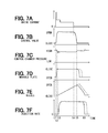
- FIGS. 7A to 7F are time charts for explaining operation of the fuel injection valve of the first embodiment
- FIG. 8 is a schematically enlarged bottom view showing a relevant portion of a fixed plate according to a second embodiment of the present disclosure
- FIG. 9 is a schematically enlarged bottom view showing a relevant portion of a fixed plate according to a third embodiment of the present disclosure.
- FIG. 10 is a schematically enlarged bottom view showing a relevant portion of a fixed plate according to a fourth embodiment of the present disclosure.
- FIG. 11 is a schematically enlarged cross sectional view showing relevant portions of a fixed plate and a movable plate according to a fifth embodiment of the present disclosure.
- FIG. 12 is a schematically enlarged cross sectional view showing relevant portions of a fixed plate and a movable plate according to a prior art fuel injection valve.
- a fuel injection valve is applied to an internal combustion engine (hereinafter, an engine) mounted in a vehicle.
- the engine in each of the embodiments is, for example, a compression-ignition type engine, such as a diesel engine.
- a compression-ignition type engine such as a diesel engine.
- the same reference numerals are given to the same or similar portions and/or structures throughout the embodiments, for the purpose of eliminating repeated explanation.
- a fuel injection valve 1 shown in FIG. 1 is operated by a drive current outputted from an electronic control unit 2 (hereinafter, the ECU 2 ).
- the ECU 2 calculates a target injection amount based on engine load, engine rotational speed and so on.
- the ECU 2 calculates an injection time period, which corresponds to the target injection amount, depending on pressure of high pressure fuel to be supplied to the fuel injection valve 1 .
- the ECU 2 calculates a power-supply time period depending on the above calculated injection time period, wherein a delay time for starting fuel injection as well as a delay time for terminating the fuel injection is taken into consideration. Then, the drive current is supplied to the fuel injection valve 1 during the power-supply time period.
- the fuel injection valve 1 is composed of a holder 10 made of metal, a fixed plate 20 and a nozzle body 30 , wherein the fixed plate 20 and the nozzle body 30 are assembled to the holder 10 by a retaining nut 40 .
- the holder 10 , the fixed plate 20 and the nozzle body 30 are collectively referred to as an injection body.
- a needle 50 (a valve body) is movably accommodated in the nozzle body 30 .
- Injection ports 32 are formed at a forward end of the nozzle body 30 in order to inject high pressure fuel.
- a valve body surface 52 formed in the valve body 50 is separated from a valve seat surface 33 formed in the nozzle body 30 , the injection ports 32 are opened so as to inject the fuel.
- the injection ports 32 are closed so as to terminate the fuel injection.
- High pressure fluid paths 11 , 21 , 31 and 51 are formed in the injection body ( 10 , 20 , 30 ) in order to introduce the high pressure fuel to the injection ports 32 .
- the high pressure fuel is supplied to the fuel injection valve 1 from an outside component (not shown), that is, a common rail (a pressure accumulating device).
- the high pressure fluid paths 11 , 21 , 31 and 51 are formed in each of the holder 10 , the fixed plate 20 and the nozzle body 30 .
- the high pressure fluid path 51 is a fluid path formed between the nozzle body 30 and the valve body 50 .
- An electric actuator 60 having a solenoid coil 61 or a piezoelectric element is provided in the holder 10 .
- the electric actuator 60 shown in FIG. 1 has the solenoid coil 61 , a piston 62 , a control valve 63 and a spring SP 1 .
- the drive current is supplied to the solenoid coil 61 to generate electromagnetic force
- the piston 62 is attracted by the electromagnetic force and the control valve 63 is moved to a control-valve opening position (as shown in FIG. 7A and FIG. 7B ).
- the piston 62 is pushed down by a spring force of the spring SP 1 so that the control valve 63 is moved to a control-valve closing position.
- a cylindrical member 70 is fixed to a lower end surface of the fixed plate 20 .
- An upper end portion of the valve body 50 is movably inserted into the cylindrical member 70 , so that the valve body 50 can be moved in an upward direction and in a downward direction.
- the upward direction is an axial direction of the fuel injection valve 1 toward an opposite side of the injection ports 32
- the downward direction is the axial direction of the fuel injection valve 1 toward the injection ports 32 .
- a high pressure passage 22 for supplying the high pressure fuel into the pressure control chamber 71 and a low pressure passage 23 for discharging the fuel from the pressure control chamber 71 are respectively formed in the fixed plate 20 .
- An orifice 23 a is formed at a downstream side of the low pressure passage 23 .
- An outlet port of the low pressure passage 23 is opened or closed by the control valve 63 .
- the high pressure passage 22 is bifurcated from the high pressure fluid paths 11 and 21 .
- An orifice 22 a is formed at a downstream side of the high pressure passage 22 .
- a movable plate 80 of a disc shape is movably accommodated in the pressure control chamber 71 , so that the movable plate 80 is movable in the upward and downward direction.
- a projection 82 of a circular shape projecting in the upward direction is formed at an upper end surface of the movable plate 80 .
- a high pressure port 22 b (which is an outlet port of the high pressure passage 22 ) is closed by the projection 82 .
- FIG. 3 shows a condition of the movable plate 80 , which is separated from the lower end surface of the fixed plate 20 and thereby the high pressure port 22 b is opened.
- a through-hole 81 is formed in the movable plate 80 in order to communicate a low pressure port 23 c (which is an inlet port of the low pressure passage 23 ) and the pressure control chamber 71 with each other.
- An orifice 81 a is formed at a downstream side of the through-hole 81 (at an upper side of the movable plate 80 ). According to the above structure, the pressure control chamber 71 is continuously communicated to the low pressure passage 23 , even when the movable plate 80 is brought into contact with the fixed plate 20 to close the high pressure port 22 b.
- the low pressure port 23 c is formed in a circular shape at a center of the lower end surface of the fixed plate 20 .
- the high pressure port 22 b which is formed at a downstream side of the orifice 22 a , is formed in an annular shape at the lower end surface of the fixed plate 20 so as to surround the low pressure port 23 c .
- an annular recessed portion 24 is further formed at the lower end surface of the fixed plate 20 so as to surround the high pressure port 22 b .
- a gap 72 which is formed between an outer peripheral wall of the movable plate 80 and an inner peripheral wall of the cylindrical member 70 , has a function as a fuel passage so that the high pressure fuel in the high pressure passage 22 flows into the pressure control chamber 71 through the gap 72 .
- the movable plate 80 moves in the downward direction to open the high pressure port 22 b , the high pressure fuel flows from the high pressure passage 22 into the pressure control chamber 71 through the annular recessed portion 24 and the gap 72 , as indicated by arrows Y in FIG. 3 .
- first wall portion 25 a portion of the lower end surface of the fixed plate 20 (a contact surface) for partitioning the high pressure port 22 b from the low pressure port 23 c is referred to as a first wall portion 25 .
- second wall portion 26 Another portion of the lower end surface of the fixed plate 20 for partitioning the annular recessed portion 24 from the high pressure port 22 b is referred to as a second wall portion 26 .
- each of the first and second wall portions 25 and 26 extends in an annular form along the high pressure port 22 b .
- Lower end surfaces of the first wall portion 25 are referred to as first contacting surfaces 25 a and 25 b
- second contacting surfaces 26 a and 26 b lower end surfaces of the second wall portion 26 are referred to as second contacting surfaces 26 a and 26 b .
- the first and second contacting surfaces 25 a , 25 b , 26 a and 26 b among the lower end surfaces of the fixed plate 20 are brought into contact with the upper end surface of the movable plate 80 .
- pushing force to the fixed plate 20 by the movable plate 80 is received by the first and second contacting surfaces 25 a , 25 b , 26 a and 26 b.
- An outer diameter D1 of the projection 82 is made larger than an outer diameter of the second wall portion 26 , so that an outer peripheral portion of the projection 82 is located within an area of the annular recessed portion 24 even when the movable plate 80 is displaced within the gap 72 in a radial direction of the fuel injection valve 1 (in a horizontal direction in FIG. 5 ).
- a first annular groove 25 m is formed at the lower end surface of the first wall portion 25 , wherein the first annular groove 25 m is recessed in a direction away from the movable plate 80 .
- a second annular groove 26 m is formed at the lower end surface of the second wall portion 26 , wherein the second annular groove 26 m is recessed in the direction away from the movable plate 80 .
- each of the first and second annular grooves 25 m and 26 m respectively extends in an annular form along the first and second wall portions 25 and 26 .
- the lower end surface of the first wall portion 25 is divided by the first annular grove 25 m into two contacting surfaces, that is, the first contacting surface 25 a on a side closer to the high pressure port 22 b and the other first contacting surface 25 b on a side closer to the low pressure port 23 c .
- the lower end surface of the second wall portion 26 is divided by the second annular groove 26 m into two contacting surfaces, that is, the second contacting surface 26 a on a side closer to the high pressure port 22 b and the other second contacting surface 26 b on a side closer to the annular recessed portion 24 .
- a first communication groove 25 n is formed at the lower end surface of the first wall portion 25 (that is, the first contacting surface 25 b ), so that the first annular groove 25 m and the low pressure passage 23 c are communicated to each other.
- a second communication groove 26 n is formed at the lower end surface of the second wall portion 26 (that is, the second contacting surface 26 b ), so that the second annular groove 26 m and the annular recessed portion 24 are communicated to each other.
- each of the first contacting surface 25 a and the second contacting surface 26 a both of which are formed on the sides closer to the high pressure port 22 b , is formed as a complete annular shape extending along the high pressure port 22 b .
- each of the first contacting surface 25 b and the second contacting surface 26 b which are formed at the sides opposite to the high pressure port 22 b , is divided by the first and the second communication grooves 25 n and 26 n.
- the first contacting surface 25 a at which the first communication groove 25 n is not formed, brings out the sealing function among the lower end surfaces of the first wall portion 25 , while the first contacting surface 25 b on the opposite side to the high pressure port 22 b does not have the sealing function.
- the second contacting surface 26 a at which the second communication groove 26 n is not formed, brings out the sealing function among the lower end surfaces of the second wall portion 26 , while the second contacting surface 26 b on the opposite side to the high pressure port 22 b does not have the sealing function.
- the high pressure port 22 b is closed by the first and second contacting surfaces 25 a and 26 a .
- the first communication groove 25 n and the first annular groove 25 m are filled with the low pressure fuel of the low pressure port 23 c
- the second communication groove 26 n and the second annular groove 26 m are filled with fuel of the annular recessed portion 24 , in which the fuel of control pressure is filled.
- P1 is a pressure in the high pressure passage 22
- P2 is a pressure in the pressure control chamber 71
- P3 is a pressure in the low pressure passage 23 , wherein “P1”>“P2”>“P3”.
- “F1” is a force, which the upper end surface of the movable plate 80 receives by the pressure “P3” of the low pressure port 23 c in the plate-contacted condition (in which the movable plate 80 is in contact with the fixed plate 20 ).
- “F2” is a force, which the upper end surface of the movable plate 80 receives by the pressure “P1” of the high pressure port 22 b in the plate-contacted condition.
- “F3” is a force, which the upper end surface of the movable plate 80 (the outer peripheral end surface of the movable plate 80 outside of the second wall portion 26 ) receives by the pressure “P2” of the pressure control chamber 71 .
- “F4” is a force, which the lower end surface of the movable plate 80 receives by the pressure “P2” of the pressure control chamber 71 .
- the low pressure passage 23 is communicated to a low pressure fluid path 12 ( FIG. 2 ) so that the fuel in the pressure control chamber 71 starts its fuel discharge to an outside of the fuel injection valve 1 via the low pressure passage 23 and the low pressure fluid path 12 .
- the fuel discharge decreases the fuel pressure in a space between the upper end surface of the movable plate 80 and the lower end surface of the fixed plate 20 (that is, the fuel pressure at the low pressure port 23 c ).
- the movable plate 80 starts its upward movement depending on the decrease of the fuel pressure and the movable plate 80 is brought into contact with the fixed plate 20 at a timing “t2”. Namely, the movable plate 80 closes the high pressure port 22 b to thereby block off the communication between the high pressure passage 22 and the pressure control chamber 71 .
- the fuel pressure in the pressure control chamber 71 is rapidly decreased, so that the valve body 50 is lifted up at a high speed in a direction toward the pressure control chamber 71 .
- the valve body 50 starts its upward movement (the displacement) at a timing “t3”.
- the fuel pressure in the pressure control chamber 71 is maintained at almost a constant value, because of a volume reduction of the pressure control chamber 71 .
- the fuel discharge through the low pressure passage 23 is terminated.
- the termination of the fuel discharge increases at first the fuel pressure in the space between the upper end surface of the movable plate 80 and the lower end surface of the fixed plate 20 (that is, the fuel pressure in the low pressure port 23 c ).
- the force “F1” is thereby increased so that the total force “F1+F2+F3” for pushing down the movable plate 80 is increased.
- the movable plate 80 which has been in the plate-contacted condition is separated from the fixed plate 20 at a timing “t5”. More exactly, the movable plate 80 opens the high pressure port 22 b to thereby communicate the high pressure passage 22 to the pressure control chamber 71 . Then, the fuel pressure in the pressure control chamber 71 is rapidly increased to push down the valve body 50 at a high speed. The valve body 50 is seated on the valve seat surface 33 at a timing “t6”, which corresponds to the valve-body closing condition.
- the first annular groove 25 m is formed at the lower end surface of the first wall portion 25 , wherein the first wall portion 25 separates the high pressure port 22 b and the low pressure port 23 c from each other and the first annular groove 25 m holds the fuel together with the movable plate 80 being in contact with the fixed plate 20 . Therefore, the linking force “Flink” can be reduced when the first sealing surface 82 a of the movable plate 80 is going to be separated from the lower end surface of the first wall portion 25 (that is, the first contacting surfaces 25 a and 25 b ).
- the fuel flows from the high pressure port 22 b into a space between the first sealing surface 82 a and the first contacting surface 25 a , as indicated by an arrow A in FIG. 6 .
- the fuel flows from the low pressure port 23 c into a space between the first sealing surface 82 a and the other first contacting surface 25 b , as indicated by an arrow B in FIG. 6 .
- the fuel flows from the first annular groove 25 m into the respective spaces, as indicated by arrows C and D in FIG. 6 .
- the linking force generated between the movable plate 80 and the fixed plate 20 is reduced.
- the second annular groove 26 m is formed at the lower end surface of the second wall portion 26 , wherein the second wall portion 26 separates the high pressure port 22 b and the annular recessed portion 24 from each other and the second annular groove 26 m holds the fuel together with the movable plate 80 being in contact with the fixed plate 20 . Therefore, the linking force can be reduced when the second sealing surface 82 b of the movable plate 80 is going to be separated from the lower end surface of the second wall portion 26 (that is, the second contacting surfaces 26 a and 26 b ).
- the fuel flows from the high pressure port 22 b into a space between the second sealing surface 82 b and the second contacting surface 26 a , as indicated by an arrow E in FIG. 6 .
- the fuel flows from the annular recessed portion 24 into a space between the second sealing surface 82 b and the other second contacting surface 26 b , as indicated by an arrow F in FIG. 6 .
- the fuel flows from the second annular groove 26 m into the respective spaces, as indicated by arrows G and H in FIG. 6 .
- the linking force generated between the movable plate 80 and the fixed plate 20 is reduced.
- the linking force can be reduced as above, it is possible to suppress generation of variation relating to timings for opening the high pressure port 22 b . It is, therefore, possible to suppress generation of variation relating to timing for closing the valve body 50 by increasing the back pressure of the valve body 50 . Variation of the fuel injection amount can be made smaller.
- the first communication groove 25 n is formed at the first contacting surface 25 b in order to communicate the first annular groove 25 m with the low pressure port 23 c in the plate-contacted condition (in which the movable plate 80 is in contact with the fixed plate 20 ).
- the fuel flows from the first annular groove 25 m into the spaces between the first contacting surfaces 25 a and 25 b and the first sealing surface 82 a .
- the fuel flows from the low pressure port 23 c to the first annular groove 25 m through the first communication groove 25 n . It is, therefore, possible to avoid a situation that negative pressure is generated in the first communication groove 25 n at a moment when the movable plate 80 is going to be separated from the fixed plate 20 . It is, thereby, possible to facilitate that the fuel flows into the spaces between the first contacting surfaces 25 a and 25 b and the first sealing surface 82 a . Thus, the linking force can be further reduced.
- the second communication groove 26 n is formed at the second contacting surface 26 b in order to communicate the second annular groove 26 m with the annular recessed portion 24 in the plate-contacted condition.
- the fuel flows from the second annular groove 26 m into the spaces between the second contacting surfaces 26 a and 26 b and the second sealing surface 82 b .
- the fuel flows from the annular recessed portion 24 to the second annular groove 26 m through the second communication groove 26 n . It is, therefore, possible to avoid a situation that negative pressure is generated in the second communication groove 26 n at the moment when the movable plate 80 is going to be separated from the fixed plate 20 . It is, thereby, possible to facilitate that the fuel flows into the spaces between the second contacting surfaces 26 a and 26 b and the second sealing surface 82 b .
- the linking force can be further reduced.
- the first communication groove 25 n communicates the first annular groove 25 m to the low pressure port 23 c , among the high pressure port 22 b and the low pressure port 23 c .
- the second communicating groove 26 n communicates the second annular groove 26 m to the annular recessed portion 24 , among the high pressure port 22 b and the annular recessed portion 24 .
- each of the first and second annular grooves 25 m and 26 m is communicated to the respective opposite sides of the high pressure port 22 b (that is, the low pressure port 23 c and the annular recessed portion 24 ). It is, therefore, possible to suppress an increase of the area of the movable plate 80 for receiving the high pressure “P1”. Namely, it is possible to obtain the sufficient amount of the pushing force “F” of the movable plate 80 , to overcome the above possible problem.
- the first annular groove 25 m is formed in the annular shape, which extends along the first contacting surfaces 25 a and 25 b and the first sealing surface 82 a
- the second annular groove 26 m is likewise formed in the annular shape, which extends along the second contacting surfaces 26 a and 26 b and the second sealing surface 82 b.
- a length of the first and second annular grooves 25 m and 26 m can be made longer than that of a case, in which the first and second grooves 25 m and 26 m have other shapes than the annular shape. It is, therefore, possible to make areas of the respective spaces between the contacting surfaces 25 a , 25 b , 26 a and 26 b and the sealing surfaces 82 a and 82 b larger, into which the fuel flows from the grooves 25 m and 26 m . As a result, it is possible to facilitate the flow-in of the fuel into the spaces between the contacting surfaces and the sealing surfaces, to thereby further reduce the linking force.
- the first and second annular grooves 25 m and 26 m may be formed not at the lower end surface of the fixed plate 20 (the first embodiment) but at the upper end surface of the movable plate 80 .
- the first and second annular grooves are designated by 82 am and 82 bm .
- the present embodiment is more advantageous in that the first and second annular grooves 25 m and 26 m are not displaced from the sealing surfaces 82 a and 82 b formed on the upper end surface of the movable plate 80 .
- the first communication groove 25 n communicates the first annular groove 25 m to the low pressure port 23 c
- the second communication groove 26 n communicates the second annular groove 26 m to the annular recessed portion 24 in the plate-contacted condition.
- the first communication groove 25 n communicates the first annular groove 25 m to the high pressure port 22 b
- the second communication groove 26 n also communicates the second annular groove 26 m to the high pressure port 22 b.
- the first communication groove 25 n communicates the first annular groove 25 m to the low pressure port 23 c
- the second communication groove 26 n communicates the second annular groove 26 m to the high pressure port 22 b
- the first communication groove 25 n communicates the first annular groove 25 m to the high pressure port 22 b
- the second communication groove 26 n communicates the second annular groove 26 m to the annular recessed portion 24 .
- the communication grooves 25 n and 26 n are respectively formed, so that neither the first contacting surface 25 b at which the first communication groove 25 n is formed nor the second contacting surface 26 b at which the second communication groove 26 n is formed brings out the sealing function.
- each of the grooves 25 m and 26 m is formed in the annular shape.
- multiple non-annular first grooves 25 m are formed at a first contacting surface 25 c , which is a lower end surface of the first wall portion 25 .
- multiple non-annular second grooves 26 m are formed at a second contacting surface 26 c , which is a lower end surface of the second wall portion 26 .
- the communication grooves 25 n and 26 n are removed in the fourth embodiment.
- first annular or non-annular groove(s) 25 m and the second annular or non-annular groove(s) 26 m are formed at the lower end surfaces of the fixed plate 20 .
- a first annular groove 82 am and a second annular groove 82 bm are formed at the upper end surface of the movable plate 80 .
- a portion of the upper end surface of the movable plate 80 which is opposed to the lower end surface 25 c (the first contacting surface) of the first wall portion 25 , corresponds to the first sealing surface 82 a .
- the first annular grove 82 am is formed at the first sealing surface 82 a .
- a portion of the upper end surface of the movable plate 80 which is opposed to the lower end surface 26 c (the second contacting surface) of the second wall portion 26 , corresponds to the second sealing surface 82 b .
- the second annular groove 82 bm is formed at the second sealing surface 82 b.
- the second wall portion 26 is formed at the lower end surface of the fixed plate 20 so as to separate the high pressure port 22 b and the annular recessed portion 24 from each other in the plate-contacted condition.
- the second wall portion 26 may be removed.
- the second contacting surfaces 26 a , 26 b or 26 c and the second sealing surface 82 b can be removed.
- the second groove(s) 26 m and 82 bm may be removed.
- the multiple non-annular grooves 25 m and 26 m are formed at the respective contacting surfaces 25 c and 26 c . It may be so modified that a part of an area for the lower end surfaces of the first and second wall portions 25 and 26 is made as a rough surface during a surface-finish process. And such rough surface portions may be used as the grooves 25 m and 26 m.
- annular groove 25 m or 26 m is formed at each of the first and second wall portions 25 and 26 .
- Multiple annular grooves may be formed at the lower end surface(s) of the first and/or the second wall portions.
- the displacement of the movable plate 80 in the vertical direction depends on the balance among the forces “F1”, “F2”, “F3” and “F4” produced by the fuel pressure.
- a spring may be provided in order to apply a spring force to the movable plate 80 .
- the spring force may be applied to the movable plate 80 in a direction toward the fixed plate 20 .
Landscapes
- Engineering & Computer Science (AREA)
- Chemical & Material Sciences (AREA)
- Combustion & Propulsion (AREA)
- Mechanical Engineering (AREA)
- General Engineering & Computer Science (AREA)
- Physics & Mathematics (AREA)
- Fluid Mechanics (AREA)
- Fuel-Injection Apparatus (AREA)
Applications Claiming Priority (2)
| Application Number | Priority Date | Filing Date | Title |
|---|---|---|---|
| JP2012-249581 | 2012-11-13 | ||
| JP2012249581A JP5641035B2 (ja) | 2012-11-13 | 2012-11-13 | 燃料噴射弁 |
Publications (2)
| Publication Number | Publication Date |
|---|---|
| US20140131483A1 US20140131483A1 (en) | 2014-05-15 |
| US9169813B2 true US9169813B2 (en) | 2015-10-27 |
Family
ID=50555971
Family Applications (1)
| Application Number | Title | Priority Date | Filing Date |
|---|---|---|---|
| US14/055,352 Active 2034-05-22 US9169813B2 (en) | 2012-11-13 | 2013-10-16 | Fuel injection valve |
Country Status (4)
| Country | Link |
|---|---|
| US (1) | US9169813B2 (ja) |
| JP (1) | JP5641035B2 (ja) |
| CN (1) | CN103807069B (ja) |
| DE (1) | DE102013112227A1 (ja) |
Families Citing this family (9)
| Publication number | Priority date | Publication date | Assignee | Title |
|---|---|---|---|---|
| GB201414669D0 (en) * | 2014-08-19 | 2014-10-01 | Delphi International Operations Luxembourg S.�.R.L. | Control valve arrangement |
| JP6256440B2 (ja) * | 2015-06-26 | 2018-01-10 | 株式会社デンソー | インジェクタ |
| WO2016208130A1 (ja) * | 2015-06-26 | 2016-12-29 | 株式会社デンソー | インジェクタ |
| JP6962039B2 (ja) * | 2017-07-12 | 2021-11-05 | 株式会社デンソー | 燃料噴射装置 |
| WO2019065413A1 (ja) * | 2017-09-29 | 2019-04-04 | 株式会社デンソー | 燃料噴射弁 |
| JP6741052B2 (ja) * | 2017-09-29 | 2020-08-19 | 株式会社デンソー | 燃料噴射弁 |
| CN108506130A (zh) * | 2018-04-18 | 2018-09-07 | 莆田市宏业精密机械有限公司 | 减少高压共轨燃油动态泄漏的喷油器 |
| JP2019203406A (ja) * | 2018-05-22 | 2019-11-28 | 株式会社Soken | 燃料噴射弁 |
| US11591995B2 (en) * | 2020-09-15 | 2023-02-28 | Caterpillar Inc. | Fuel injector having valve seat orifice plate with valve seat and drain and re-pressurization orifices |
Citations (13)
| Publication number | Priority date | Publication date | Assignee | Title |
|---|---|---|---|---|
| US20030111547A1 (en) * | 2001-10-12 | 2003-06-19 | Mario Ricco | Internal combustion engine fuel injector |
| US20040195348A1 (en) * | 2003-02-28 | 2004-10-07 | Lewis Stephen Robert | Leak arrest volume for reducing component separation and fuel injector using same |
| JP2006322430A (ja) | 2005-05-20 | 2006-11-30 | Denso Corp | 燃料噴射装置 |
| JP2007205263A (ja) | 2006-02-02 | 2007-08-16 | Denso Corp | 燃料噴射装置用電磁式アクチュエータ |
| US20100301143A1 (en) | 2009-06-02 | 2010-12-02 | Denso Corporation | Fuel injection device |
| US20110198418A1 (en) | 2010-02-18 | 2011-08-18 | Denso Corporation | Fuel injection device |
| JP2011169242A (ja) | 2010-02-18 | 2011-09-01 | Denso Corp | 燃料噴射装置 |
| US20110240768A1 (en) * | 2010-03-31 | 2011-10-06 | Denso Corporation | Fuel injection device |
| US20120012680A1 (en) * | 2010-07-14 | 2012-01-19 | Denso Corporation | Fuel injection device |
| US20120042852A1 (en) * | 2010-03-31 | 2012-02-23 | Masato Yamada | Fuel injection device |
| US20120103308A1 (en) * | 2010-10-28 | 2012-05-03 | Caterpillar, Inc. | Two-Way Valve Orifice Plate for a Fuel Injector |
| US20120111965A1 (en) * | 2010-11-08 | 2012-05-10 | Caterpillar Inc. | Fuel Injector With Needle Control System That Includes F, A, Z And E Orifices |
| US20120152206A1 (en) * | 2010-12-17 | 2012-06-21 | Denso Corporation | Fuel injection device |
Family Cites Families (1)
| Publication number | Priority date | Publication date | Assignee | Title |
|---|---|---|---|---|
| JP4428357B2 (ja) * | 2006-04-03 | 2010-03-10 | 株式会社デンソー | 燃料噴射弁 |
-
2012
- 2012-11-13 JP JP2012249581A patent/JP5641035B2/ja active Active
-
2013
- 2013-10-16 US US14/055,352 patent/US9169813B2/en active Active
- 2013-11-07 DE DE102013112227.2A patent/DE102013112227A1/de active Pending
- 2013-11-12 CN CN201310560360.2A patent/CN103807069B/zh active Active
Patent Citations (14)
| Publication number | Priority date | Publication date | Assignee | Title |
|---|---|---|---|---|
| US20030111547A1 (en) * | 2001-10-12 | 2003-06-19 | Mario Ricco | Internal combustion engine fuel injector |
| US20040195348A1 (en) * | 2003-02-28 | 2004-10-07 | Lewis Stephen Robert | Leak arrest volume for reducing component separation and fuel injector using same |
| JP2006322430A (ja) | 2005-05-20 | 2006-11-30 | Denso Corp | 燃料噴射装置 |
| JP2007205263A (ja) | 2006-02-02 | 2007-08-16 | Denso Corp | 燃料噴射装置用電磁式アクチュエータ |
| US20100301143A1 (en) | 2009-06-02 | 2010-12-02 | Denso Corporation | Fuel injection device |
| JP2011169242A (ja) | 2010-02-18 | 2011-09-01 | Denso Corp | 燃料噴射装置 |
| US20110198418A1 (en) | 2010-02-18 | 2011-08-18 | Denso Corporation | Fuel injection device |
| JP2011169241A (ja) | 2010-02-18 | 2011-09-01 | Denso Corp | 燃料噴射装置 |
| US20110240768A1 (en) * | 2010-03-31 | 2011-10-06 | Denso Corporation | Fuel injection device |
| US20120042852A1 (en) * | 2010-03-31 | 2012-02-23 | Masato Yamada | Fuel injection device |
| US20120012680A1 (en) * | 2010-07-14 | 2012-01-19 | Denso Corporation | Fuel injection device |
| US20120103308A1 (en) * | 2010-10-28 | 2012-05-03 | Caterpillar, Inc. | Two-Way Valve Orifice Plate for a Fuel Injector |
| US20120111965A1 (en) * | 2010-11-08 | 2012-05-10 | Caterpillar Inc. | Fuel Injector With Needle Control System That Includes F, A, Z And E Orifices |
| US20120152206A1 (en) * | 2010-12-17 | 2012-06-21 | Denso Corporation | Fuel injection device |
Also Published As
| Publication number | Publication date |
|---|---|
| US20140131483A1 (en) | 2014-05-15 |
| DE102013112227A1 (de) | 2014-05-15 |
| CN103807069A (zh) | 2014-05-21 |
| CN103807069B (zh) | 2017-04-12 |
| JP2014098323A (ja) | 2014-05-29 |
| JP5641035B2 (ja) | 2014-12-17 |
Similar Documents
| Publication | Publication Date | Title |
|---|---|---|
| US9169813B2 (en) | Fuel injection valve | |
| US9651008B2 (en) | Fuel injection valve | |
| US6802298B2 (en) | Pressure control valve for controlling operation of fuel injector | |
| CN104093969B (zh) | 具备电磁驱动型的吸入阀的高压燃料供给泵 | |
| CN114151254B (zh) | 压电直驱-先导双作用的双针阀喷油器 | |
| CN101849098B (zh) | 喷射系统和用于制造喷射系统的方法 | |
| US20080099585A1 (en) | Fuel injection valve | |
| JP6474694B2 (ja) | 燃料噴射ノズル | |
| US20210285412A1 (en) | Fuel injection valve | |
| CN209146336U (zh) | 一种燃油气控切断阀 | |
| CN111051681B (zh) | 用于控制喷射器的装置 | |
| JP2016050561A (ja) | 燃料噴射弁 | |
| JP6662629B2 (ja) | 燃料噴射弁 | |
| JP2005511965A (ja) | 内燃機関のための燃料噴射装置 | |
| JP6284860B2 (ja) | 燃料噴射弁 | |
| JP5157988B2 (ja) | 燃料噴射装置 | |
| CN114738155B (zh) | 燃油喷射阀总成、发动机及车辆 | |
| CN108412653A (zh) | 一种共轨喷油器 | |
| US20230130775A1 (en) | Fuel injector for internal combustion engines | |
| JP7064363B2 (ja) | 燃料噴射装置 | |
| JP2009047151A (ja) | 可変噴霧角・噴孔型燃料噴射ノズル | |
| KR101912021B1 (ko) | 연료레일의 압력조절밸브 | |
| US9732715B2 (en) | Two stage valve with conical seat for flow shut-off and spool knife edge for metering flow control | |
| CN109442047A (zh) | 一种燃油气控切断阀 | |
| JP5462139B2 (ja) | 燃料噴射弁 |
Legal Events
| Date | Code | Title | Description |
|---|---|---|---|
| AS | Assignment |
Owner name: DENSO CORPORATION, JAPAN Free format text: ASSIGNMENT OF ASSIGNORS INTEREST;ASSIGNOR:ADACHI, NAOFUMI;REEL/FRAME:031417/0472 Effective date: 20131003 |
|
| FEPP | Fee payment procedure |
Free format text: PAYOR NUMBER ASSIGNED (ORIGINAL EVENT CODE: ASPN); ENTITY STATUS OF PATENT OWNER: LARGE ENTITY |
|
| STCF | Information on status: patent grant |
Free format text: PATENTED CASE |
|
| MAFP | Maintenance fee payment |
Free format text: PAYMENT OF MAINTENANCE FEE, 4TH YEAR, LARGE ENTITY (ORIGINAL EVENT CODE: M1551); ENTITY STATUS OF PATENT OWNER: LARGE ENTITY Year of fee payment: 4 |
|
| MAFP | Maintenance fee payment |
Free format text: PAYMENT OF MAINTENANCE FEE, 8TH YEAR, LARGE ENTITY (ORIGINAL EVENT CODE: M1552); ENTITY STATUS OF PATENT OWNER: LARGE ENTITY Year of fee payment: 8 |