US8968499B2 - Optical sheet laminating method, optical sheet laminating device and program used therewith, and display device - Google Patents
Optical sheet laminating method, optical sheet laminating device and program used therewith, and display device Download PDFInfo
- Publication number
- US8968499B2 US8968499B2 US13/104,607 US201113104607A US8968499B2 US 8968499 B2 US8968499 B2 US 8968499B2 US 201113104607 A US201113104607 A US 201113104607A US 8968499 B2 US8968499 B2 US 8968499B2
- Authority
- US
- United States
- Prior art keywords
- optical
- sheet
- optical sheet
- display panel
- holding head
- Prior art date
- Legal status (The legal status is an assumption and is not a legal conclusion. Google has not performed a legal analysis and makes no representation as to the accuracy of the status listed.)
- Active, expires
Links
Images


Classifications
-
- G—PHYSICS
- G02—OPTICS
- G02B—OPTICAL ELEMENTS, SYSTEMS OR APPARATUS
- G02B5/00—Optical elements other than lenses
- G02B5/04—Prisms
-
- G—PHYSICS
- G02—OPTICS
- G02B—OPTICAL ELEMENTS, SYSTEMS OR APPARATUS
- G02B3/00—Simple or compound lenses
- G02B3/0006—Arrays
- G02B3/0037—Arrays characterized by the distribution or form of lenses
- G02B3/005—Arrays characterized by the distribution or form of lenses arranged along a single direction only, e.g. lenticular sheets
-
- B—PERFORMING OPERATIONS; TRANSPORTING
- B32—LAYERED PRODUCTS
- B32B—LAYERED PRODUCTS, i.e. PRODUCTS BUILT-UP OF STRATA OF FLAT OR NON-FLAT, e.g. CELLULAR OR HONEYCOMB, FORM
- B32B38/00—Ancillary operations in connection with laminating processes
- B32B38/18—Handling of layers or the laminate
- B32B38/1825—Handling of layers or the laminate characterised by the control or constructional features of devices for tensioning, stretching or registration
- B32B38/1833—Positioning, e.g. registration or centering
- B32B38/1841—Positioning, e.g. registration or centering during laying up
-
- B—PERFORMING OPERATIONS; TRANSPORTING
- B32—LAYERED PRODUCTS
- B32B—LAYERED PRODUCTS, i.e. PRODUCTS BUILT-UP OF STRATA OF FLAT OR NON-FLAT, e.g. CELLULAR OR HONEYCOMB, FORM
- B32B41/00—Arrangements for controlling or monitoring lamination processes; Safety arrangements
-
- G—PHYSICS
- G02—OPTICS
- G02B—OPTICAL ELEMENTS, SYSTEMS OR APPARATUS
- G02B3/00—Simple or compound lenses
- G02B3/0006—Arrays
- G02B3/0012—Arrays characterised by the manufacturing method
-
- G—PHYSICS
- G02—OPTICS
- G02B—OPTICAL ELEMENTS, SYSTEMS OR APPARATUS
- G02B5/00—Optical elements other than lenses
- G02B5/02—Diffusing elements; Afocal elements
-
- B—PERFORMING OPERATIONS; TRANSPORTING
- B32—LAYERED PRODUCTS
- B32B—LAYERED PRODUCTS, i.e. PRODUCTS BUILT-UP OF STRATA OF FLAT OR NON-FLAT, e.g. CELLULAR OR HONEYCOMB, FORM
- B32B41/00—Arrangements for controlling or monitoring lamination processes; Safety arrangements
- B32B2041/04—Detecting wrong registration, misalignment, deviation, failure
-
- B—PERFORMING OPERATIONS; TRANSPORTING
- B32—LAYERED PRODUCTS
- B32B—LAYERED PRODUCTS, i.e. PRODUCTS BUILT-UP OF STRATA OF FLAT OR NON-FLAT, e.g. CELLULAR OR HONEYCOMB, FORM
- B32B2307/00—Properties of the layers or laminate
- B32B2307/40—Properties of the layers or laminate having particular optical properties
-
- B—PERFORMING OPERATIONS; TRANSPORTING
- B32—LAYERED PRODUCTS
- B32B—LAYERED PRODUCTS, i.e. PRODUCTS BUILT-UP OF STRATA OF FLAT OR NON-FLAT, e.g. CELLULAR OR HONEYCOMB, FORM
- B32B2457/00—Electrical equipment
- B32B2457/20—Displays, e.g. liquid crystal displays, plasma displays
-
- Y—GENERAL TAGGING OF NEW TECHNOLOGICAL DEVELOPMENTS; GENERAL TAGGING OF CROSS-SECTIONAL TECHNOLOGIES SPANNING OVER SEVERAL SECTIONS OF THE IPC; TECHNICAL SUBJECTS COVERED BY FORMER USPC CROSS-REFERENCE ART COLLECTIONS [XRACs] AND DIGESTS
- Y10—TECHNICAL SUBJECTS COVERED BY FORMER USPC
- Y10T—TECHNICAL SUBJECTS COVERED BY FORMER US CLASSIFICATION
- Y10T428/00—Stock material or miscellaneous articles
- Y10T428/24—Structurally defined web or sheet [e.g., overall dimension, etc.]
- Y10T428/24802—Discontinuous or differential coating, impregnation or bond [e.g., artwork, printing, retouched photograph, etc.]
Definitions
- the present invention relates to an optical sheet laminating method, an optical sheet laminating device, a display device, and the like for laminating an optical sheet on a display panel.
- a unique display device capable of stereoscopic images, viewing angle controls, and the like through laminating an optical sheet such as a lenticular lens sheet, a prism sheet, or a diffusion sheet on a display panel that uses electro-optical elements such as liquid crystal has come to be used.
- FIG. 21A is a perspective view showing a lenticular lens sheet
- FIG. 21B is a schematic view showing a stereoscopic display device using the lenticular lens sheet.
- a lenticular lens sheet 110 has a flat face on one of the surfaces, and a plurality of cylindrical lenses 111 each having columnar surface and a semicircular (roughly a segment shape) cross-sectional shape are repeatedly provided in parallel on the other surface.
- a left-eye pixel 115 a and a right-eye pixel 115 b are disposed alternately on a display panel 114 by corresponding to focal points of each of the cylindrical lenses 111 .
- a left-eye image is formed in a left-eye region 120 a and a right-eye image is formed in a right-eye region 120 b , respectively, by the cylindrical lenses 111 , so that an observer can recognize a stereoscopic image.
- a normal two-dimensional image can also be displayed through driving the left-eye pixels 115 a and the right-eye pixels 115 b by a same signal.
- a display device using a lenticular lens sheet there is a plural-image simultaneous display device which displays a plurality of images simultaneously. This uses the same method as that of the stereoscopic display, with which different images can be displayed to a plurality of observers by distributing images to the observing directions by the cylindrical lenses.
- the related technique 1 it is necessary to form each marks on the optical sheet and the display panel in an order of ⁇ m for achieving the lamination accuracy in an order of ⁇ m.
- the distance of the mark on the lenticular lens sheet from the vertex of the cylindrical lens is required to be accurate in an order of ⁇ m.
- Patent Document 1 see FIG. 3 and FIG. 8
- this technique 2 this technique is referred to as “related technique 2”.
- Patent Document 2 see FIG. 39 discloses steps for laminating an optical element array sheet on a display panel by using a curved-type optical element holding head.
- An optical sheet mark is placed on the surface of the optical sheet, and a panel mark is placed on the surface of the display panel.
- a panel mark is placed on the surface of the display panel.
- a panel mark 132 is formed on a drive substrate 152 or a counter substrate 153
- an optical sheet mark 150 is formed on an optical sheet 151 . Therefore, it is necessary to align the focal point separately with the optical sheet mark 150 and the panel mark 132 when capturing the images thereof by a same camera since there are the counter substrate 153 , a polarization plate 154 , and the optical sheet 151 existing therebetween. That is, the reading accuracy of both marks depends on the feeding accuracy of the focal point direction of the camera. Further, since it takes more time for aligning the focal point, it is disadvantageous in terms of tactics.
- the position of the panel mark 132 is observed by being changed due to a refractive effect of the optical sheet 151 . Therefore, it is necessary to perform correction thereof.
- the luminance distribution of transmission light acquired by irradiating light onto the optical sheet 151 largely depends on the image forming performance of the cylindrical lens. However, in a case where variations in the radius curvatures of each of the lenses are great or in a case where there is distortion generated in the optical sheet 151 itself, for example, the luminance distribution changes nonuniformly within the surface. This leads to deterioration of the mark reading accuracy.
- the panel mark 132 is disposed directly under the optical sheet 151 .
- the external shape of the optical sheet 151 is smaller than the external shape of the display panel 131 and the external shape of the polarization plate 154 by one size.
- “the panel mark 132 comes directly under the optical sheet 151 ” means that the panel mark 132 is disposed near a display region 155 of the display panel 131 .
- the panel mark 132 which causes leak of light is formed near the display region 155 .
- the substantial contact area between the optical sheet and the sheet holding head becomes small since the optical element forming surface has fine protrusions and concaves. For this reason, there is such an issue that the force for holding the optical sheet is reduced.
- the related technique 1 reads the positional information of the optical sheet mark by using existence of light transmitting through the optical sheet
- the related technique 2 reads the positional information of the lens by using the luminance distribution of light transmitting through the optical sheet. That is, the related technique 2 acquires the positional information by using the light transmitting through the optical sheet as in the case of the related technique 1, so that it faces the same issues.
- the sheet holding head (a holding frame that holds the lenticular lens sheet) of the related technique 2 is formed with a material that exhibits light transmitting property for not disturbing imaging done by an imaging part (see paragraph 0022 of Patent Document 2). Therefore, the materials used for the sheet holding head of the related technique 2 are limited to fragile glass, plastics, and the like, so that solid metals, ceramics, and the like cannot be used.
- An exemplary object of the present invention is to provide an optical sheet laminating method and a laminating device using the method which can mount an optical sheet on a display panel with high yield and high accuracy as well as to provide a high-quality display device manufactured by using the laminating method.
- the optical sheet laminating method is a method which laminates an optical sheet having two sides constituted with an optical element face where a plurality of optical elements are formed and a no-optical-element face where the optical elements are not formed with a display panel by using a sheet holding head, and the method is characterized to include: bringing either the optical element face or the no-optical-element face to be in contact with the sheet holding head; irradiating light to contact areas between either the optical element face or the non-optical and the sheet holding head from the other one of the optical element face and the no-optical-element face; reading positional information of the contact areas from a distribution of reflected light thereof; and aligning positions of the optical sheet and the display panel based on the positional information of the contact areas, and laminating the optical sheet and the display panel.
- the optical sheet laminating device is a device which laminates an optical sheet having two sides constituted with an optical element face where a plurality of optical elements are formed and a no-optical-element face where the optical elements are not formed with a display panel, and the device is characterized to include: a sheet holding head which holds the optical sheet by making contact with either the optical element face or the no-optical-element face; a first imaging part which irradiates light to contact areas between either the optical element face or the non-optical and the sheet holding head from the other one of the optical element face or the no-optical-element face, and acquires an image of reflected light thereof; a second imaging part which acquires an image of a panel mark added to the display panel; a moving mechanism unit which moves at least either the optical sheet or the display panel in a coordinate space; and a control unit which reads positional information of the contact areas from the image acquired by the first imaging part and positional information of the panel mark from the image acquired by the second
- the display device is characterized to include the display panel to which the optical sheet is laminated by the optical sheet laminating method of the present invention.
- FIG. 1 shows schematic illustrations showing a laminating method according to a first exemplary embodiment
- FIG. 2 is a chart showing steps of the laminating method according to the first exemplary embodiment
- FIG. 3 is a schematic illustration showing a laminating device according to the first exemplary embodiment
- FIG. 4A is a block diagram showing the laminating device according to the first exemplary embodiment
- FIG. 4B is a block diagram showing an example of a control unit shown in FIG. 4A ;
- FIG. 5 is a graph showing an alignment action of the laminating device according to the first exemplary embodiment
- FIG. 6 is an image and a side view showing contact areas between a sheet holding head and an optical element face of an optical sheet according to the first exemplary embodiment
- FIG. 7A is another example of an image showing contact areas between the sheet holding head and the optical element face of the optical sheet according to the first exemplary embodiment
- FIG. 7B is a side view showing a state where the sheet holding head and a no-optical-element face of the optical sheet are in contact;
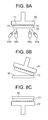
- FIGS. 8A-8C show another example of the first exemplary embodiment, in which FIG. 8 A is a schematic illustration when reading the positional information of the optical sheet by a plurality of cameras, FIG. 8B is a schematic illustration showing the sheet holding head when laminating the optical sheet, and FIG. 8C is a schematic illustration showing a case where the sheet holding head is provided on the lower side of the display panel;
- FIGS. 9A-9C show a sheet holding head according to a second exemplary embodiment, in which FIG. 9A is a perspective view, and FIG. 9B and FIG. 9C are schematic illustrations showing a positional information reading action;
- FIGS. 10A-10C show schematic illustrations showing laminating steps according to the second exemplary embodiment, in which the steps proceed in order of FIG. 10A , FIG. 10B , and FIG. 10C ;
- FIGS. 11A and 11B show perspective views of a part of the laminating step according to the second exemplary embodiment, in which FIG. 11A is a case where the contact areas between the sheet holding head and the optical sheet are in parallel to the arc tangent direction of the sheet holding head, and FIG. 11B is a case where the contact areas between the sheet holding head and the optical sheet are orthogonal to the arc tangent direction of the sheet holding head;
- FIG. 12 is a schematic illustration showing a case where the sheet holding head according to the second exemplary embodiment is provided on the lower side of the display panel;
- FIG. 13 is a graph showing an example of a relation between a laminating pressure and a lens pitch fluctuation amount before and after the lamination according to the second exemplary embodiment
- FIG. 14A is a plan view showing lenticular lenses in nonuniform lens pitches according to a third exemplary embodiment
- FIG. 14B is a graph showing a relation between the laminating pressure and the lens pitch fluctuation amount
- FIG. 14C is a graph showing a laminating pressure set to be in a proper value
- FIG. 15A is a plan view showing another example of the lenticular lenses in nonuniform lens pitches according to a third exemplary embodiment
- FIG. 15B is a first graph showing a laminating pressure set to be in a proper value
- FIG. 15C is a second graph showing a laminating pressure set to be in a proper value
- FIG. 16A shows an image and a side view showing contact areas between the sheet holding head and an optical element face of the optical sheet shown in FIG. 16B
- FIG. 16B is a perspective view showing a first optical sheet according to a fourth exemplary embodiment
- FIG. 17A shows an image and a side view showing contact areas between the sheet holding head and an optical element face of the optical sheet shown in FIG. 17B
- FIG. 17B is a perspective view showing a second optical sheet according to the fourth exemplary embodiment
- FIG. 18A is a plan view showing a third optical sheet according to the fourth exemplary embodiment
- FIG. 18B is an image showing contact areas between the sheet holding head and an optical element face of the optical sheet shown in FIG. 18A ;
- FIG. 19A is a perspective view showing a mobile terminal device on which a display device having an optical sheet laminated on a display panel by using the present invention is loaded
- FIG. 19B is a perspective view showing a fly-eye lens as an optical sheet
- FIG. 20 is a plan view showing a display panel and a panel mark of the present invention.
- FIG. 21A is a perspective view showing a lenticular lens sheet
- FIG. 21B is a schematic view showing a stereoscopic display method using the lenticular lens sheet
- FIG. 22A is a side view showing a liquid crystal display device
- FIG. 22B is a plan view showing the liquid crystal display device
- FIGS. 23A-23C show cases where the lens pitches become nonuniform within a surface of a lenticular lens sheet, in which FIG. 23A is a case where the lens pitch becomes larger towards the upper side, FIG. 23B is a case where the lens pitch becomes larger towards the center, and FIG. 23C is a case where the lens pitch becomes smaller towards the center.
- a case of using a lenticular lens sheet formed with a plurality of cylindrical lenses as an optical sheet will be described. While explanations will be provided by referring to cases where the lenticular lens sheet is used as the optical sheet in other exemplary embodiments as well, the present invention is not limited only to that.
- An optical element array including a prism sheet with a prescribed pattern formed thereon, a reflection sheet, a diffusion sheet, and the like may also be used.
- FIG. 1 is a schematic illustration showing a laminating method according to the first exemplary embodiment
- FIG. 2 is a chart showing steps of the laminating method according to the first exemplary embodiment.
- FIG. 1 and FIG. 2 explanations will be provided by referring to FIG. 1 and FIG. 2 .
- the optical sheet laminating method according to the first exemplary embodiment is for laminating an optical sheet 10 onto a display panel 30 by using a sheet holding head 20 .
- the optical sheet 10 is a lenticular lens sheet formed with a plurality of cylindrical lenses 11 as a plurality of optical elements, and the optical sheet 10 includes an optical element face 12 where the cylindrical lenses 11 are formed, and a no-optical-element face 13 where the cylindrical lenses 11 are not formed. That is, the optical element face 12 is a concave-convex face, and the no-optical-element face 13 is a flat face.
- the laminating method according to the first exemplary embodiment includes following steps.
- Steps 101 - 103 ( FIG. 1A and FIG. 1B ):
- the optical element face 12 is brought into contact with the sheet holding head 20 (step 101 )
- light 41 is irradiated from the no-optical-element face 13 to contact areas 14 between the optical element face 12 and the sheet holding head 20 (step 102 )
- the positional information of the contact areas 14 is read from the distribution of reflected light 42 thereof (step 103 ).
- a first imaging part 40 having a light source 43 and a camera 44 is used.
- the steps 101 - 103 may be executed in any orders as long as the positional information of the contact areas 14 can be read at last.
- the steps 101 - 103 may be executed in this order or may all be executed simultaneously. Further, it is also possible to bring the no-optical-element face 13 to be in contact with the sheet holding head 20 , irradiate the light 41 from the optical element face 12 to the contact areas between the no-optical-element face 13 and the sheet holding head 20 , and read the positional information from the distribution of the reflected light 42 .
- Step 104 Positional information of a panel mark 31 applied on the display panel 30 is read.
- a second imaging part 50 having a light source 53 and a camera 54 is used.
- the imaging part 50 irradiates light 51 to the panel mark 31 applied on the display panel 30 , and the positional information of the panel mark 31 is read from transmission light 52 thereof.
- the step 104 may be executed before or after the steps 101 - 103 in terms of time. If the positional information of the panel mark 31 is already known, the step 104 may be omitted.
- Step 105 Positions of the optical sheet 10 and the display panel 30 are aligned based on the positional information of the contact areas 14 and the positional information of the panel mark 31 .
- a typical alignment technique may be employed for this position alignment.
- Step 106 The optical sheet 10 and the display panel 30 are laminated.
- the optical sheet 10 and the display panel 30 are laminated by relatively moving the optical sheet 10 and the display panel 30 while keeping the optical sheet 10 and the display panel 30 in contact.
- To relatively move the optical sheet 10 and the display panel 30 is to move at least one of the optical sheet 10 and the display panel 30 .
- a typical laminating technique can be used for this lamination.
- the first exemplary embodiment uses not the transmission light but the reflected light 42 for reading the positional information of the optical sheet 10 . Therefore, the various issues of the case using the transmission light can be overcome in one effort, so that the reading accuracy of the positional information of the optical sheet 10 can be improved. This makes it possible to achieve high accuracy and to improve the yield in the optical sheet laminating step.
- FIG. 3 is a schematic view showing a laminating device of the first exemplary embodiment.
- FIG. 4A is a block diagram showing the laminating device of the first exemplary embodiment.
- FIG. 4B is a block diagram showing an example of a control unit shown in FIG. 4A .
- FIG. 5 is a graph showing an example of an alignment action executed by the laminating device of the first exemplary embodiment.
- An optical sheet laminating device 60 of the first exemplary embodiment is for laminating the optical sheet 10 on the display panel 30 by using the optical sheet laminating method according to the first exemplary embodiment, and the device 60 includes the sheet holding head 20 , the first imaging part 40 , the second imaging part 50 , a moving mechanism unit 70 , and a control unit 80 .
- the sheet holding head 20 holds the optical sheet 10 by making contact with the optical element face 12 .
- the imaging part 40 irradiates the light 41 from the no-optical-element face 13 to the contact areas 14 between the optical element face 12 and the sheet holding head 20 , and acquires an image 45 of the distribution of the reflected light 42 thereof.
- the imaging part 50 acquires an image 55 of the panel mark 31 applied on the display panel 30 .
- the moving mechanism unit 70 moves the optical sheet 10 and the display panel 30 in a coordinate space.
- the control unit 80 reads the positional information of the contact areas 14 from the image 45 acquired by the imaging part 40 as well as the positional information of the panel mark 31 from the image 55 acquired by the imaging part 50 , controls the moving mechanism unit 70 based on the positional information of the contact areas 14 and the positional information of the panel mark 31 to align the positions of the optical sheet 10 and the display panel 30 , and laminate the optical sheet 10 and the display panel 30 .
- the moving mechanism unit 70 includes an optical sheet side mechanism 71 and a display panel side mechanism 74 .
- the optical sheet side mechanism 71 is formed with a linear motor mechanism (or a stepping motor and a screw feed mechanism), a rotary mechanism, and the like, for example. It is divided into a fixed main body 72 and a head stage 73 that is movable with respect to the main body 72 .
- the head stage 73 is capable of linearly moving the sheet holding head 20 in the X-axis direction, the Y-axis direction, and Z-axis direction, respectively, and rotating in the ⁇ direction about the Z-axis direction.
- the display panel side mechanism 74 is formed with a linear motor mechanism (or a stepping motor and a screw feed mechanism) and the like, for example, and it is divided into a fixed main body 75 and a panel stage 76 that is movable with respect to the main body 75 .
- the panel stage 76 is capable of loading the display panel 30 thereon and linearly moving in the X-axis direction and the Y-axis direction, respectively.
- the head stage 73 and the panel stage 76 only need to move relatively.
- movements in the Z-axis direction and rotations in the ⁇ direction may be allotted to the panel stage 76
- movements in the Y-axis direction may be allotted only either to the head stage 73 or the panel stage 76 , for example.
- the moving mechanism unit 70 may move either the optical sheet 10 or the display panel 30 in the coordinate space. In that case, either the optical sheet side mechanism 71 or the display panel side mechanism 74 may be omitted.
- the control unit 80 includes a typical computer formed with a CPU 81 , a ROM 82 , a RAM 83 , an input/output interface 84 , and the like, for example, and operates according to a computer program and data.
- the control unit 80 receives the images 45 and 55 from the imaging parts 40 and 50 , reads the positional information of the contact areas 14 and the positional information of the panel mark 31 by an image processing program or the like, and outputs control signals 85 , 86 , 87 based on the information to the sheet holding head 20 , the optical sheet side mechanism 71 , and the display panel side mechanism 74 , respectively.
- the control signal 85 includes a signal indicating the sheet holding head 20 to start or end the holding action of the optical sheet 10 .
- the control signal 86 includes a signal for moving the head stage 73 (i.e., the optical sheet 10 ) to a prescribed coordinate.
- the control signal 87 includes a signal for moving the display panel side mechanism 74 (i.e., the display panel 30 ) to a prescribed coordinate.
- An example of the computer programs of the control unit 80 may be a program which causes the computer to execute a procedure for reading the positional information of the contact areas 14 from the image 45 acquired by the imaging part 40 , a procedure for reading the positional information of the panel mark 31 from the image 55 acquired by the imaging part 50 , and procedure for controlling the moving mechanism unit 70 based on the positional information of the contact areas 14 and the positional information of the panel mark 31 to align the positions of the optical sheet 10 and the optical display panel 30 , and laminating the optical sheet 10 and the display panel 30 .
- the alignment action executed by the laminating device 60 will be described.
- positions, magnifications, and the like of the cameras 44 and 54 are adjusted in such a manner that pixels of the cameras 44 and 54 correspond on one on one basis with the coordinates on an XY plane. Further, as shown in FIG. 5 , it is assumed that the positional information of the contact areas 14 is acquired as Ma 1 (xa 1 , ya 1 ), Ma 2 (xa 2 , ya 2 ), and the positional information of the panel mark 31 is acquired as Mb 1 (xb 1 , yb 1 ), Mb 2 (xb 2 , yb 2 ). Ma 1 and Mb 2 are defined as coordinates of vertexes of both ends of a specific single cylindrical lens 11 .
- Mb 1 and Mb 2 are defined as coordinates of two cross-shaped panel marks 31 .
- the optical sheet 10 as a lenticular lens sheet is used in a display device which provides image displays towards a plurality of viewpoints.
- the optical sheet 10 is abutted against the display face of the display panel 30 and transmits at least a part of light wavelengths of a visible light region.
- any materials whether it is a nonorganic material or an organic material may be used as long as it is a material which transmits at least a part of light with wavelengths of 400 nm-800 nm Glass or the like can be used as a nonorganic material and plastics or the like can be used as an organic material. However, in general, plastics are often used.
- plastics engineering plastics such as polymethylmetacryrate (PMMA), cyclopolyolefin (COP), polycarbonate (PC), and the like can be used.
- PMMA polymethylmetacryrate
- COP cyclopolyolefin
- PC polycarbonate
- thickness of the optical sheet 10 it is desirable to be within a range of about 0.05 mm to 0.5 mm for practical use.
- FIG. 1 shows schematic illustrations of an example of an optical sheet laminating step according to the first exemplary embodiment.
- the optical sheet is held by using the sheet holding head 20 .
- the light 41 is irradiated towards the contact areas 14 from the light source 43
- the distribution of the reflected light 42 is captured by the camera 44
- the positional information of the optical sheet 10 is read by using the acquired image 45 .
- the positional information of the panel mark 31 (see FIG. 20 ) on the display panel 30 is read by using the camera 54 .
- FIG. 1C shows schematic illustrations of an example of an optical sheet laminating step according to the first exemplary embodiment.
- an alignment action for aligning the sheet holding head 20 that holds the optical sheet 10 and the panel stage 76 (see FIG. 3 ) for fixing the display panel 30 to a prescribed position based on the both positional information to laminate the optical sheet 10 and the display panel 30 .
- the panel mark 31 (see also FIG. 20 ) is read according to the transmission light 52 , it is also possible to read it with the reflected light in a case where the material constituting the panel mark has a prescribed reflection property.
- various actions can be used as the alignment action. For example, it is possible to use a case where the sheet holding head 20 is movable to arbitrary positions and the panel stage 76 (see FIG. 3 ) is fixed, a case where the panel stage 76 is movable to arbitrary positions and the sheet holding head 20 is fixed, a case where both the sheet holding head 20 and the panel stage 76 are movable to arbitrary positions, etc.
- FIG. 6 is an image and a side view showing the contact areas between the sheet holding head and the optical element face of the optical sheet according to the first exemplary embodiment.
- FIG. 7A is an another example of an image showing the contact areas between the sheet holding head and the optical element face of the optical sheet according to the first exemplary embodiment
- FIG. 7B is a side view showing a state where the sheet holding head and the no-optical-element face of the optical sheet are in contact.
- FIG. 6 shows the image 45 when the contact areas 14 between the optical element face (lens face) 12 of the optical sheet (lenticular lens sheet) 10 and the sheet holding head 20 are captured by using the reflected light 42 .
- the vertexes of the cylindrical lenses 11 forming the lenticular lens sheet and the sheet holding head 20 are in contact linearly, and a plurality of the contact areas 14 are periodically formed according to the period of the cylindrical lenses 11 .
- the light 41 is irradiated to those contact areas 14 , the light is strongly reflected at the contact areas 14 .
- the positional information required for the alignment action between the optical sheet 10 and the display panel 30 by reading the positional information of at least two points (e.g., the points Ma 1 and Ma 2 ) along the longitudinal direction of the cylindrical lenses 11 and finding the positions and slope by utilizing a linear function connecting the two points.
- FIG. 7B shows a schematic illustration of a case where the no-optical-element face (no-lens face) 13 of the optical sheet 10 and the sheet holding head 20 are brought into contact.
- a distribution according to the lens image forming performance is acquired in the image captured by the reflected light.
- the light source 43 various light sources such as an LED light, a fluorescent light, and the like can be used, and the wavelength can be set arbitrarily according to the spectral sensitivity of a CCD within the camera 44 . This is the same for the light source 53 .
- the first exemplary embodiment is structured to read the positional information of the cylindrical lenses 11 by using the reflected light 42 , so that there is no limit set for the material of the sheet holding head 20 .
- the vacuum absorption it is possible to employ a material that is excellent for forming absorption holes, a porous material, a low surface-stiffness material which suppresses damaging to the optical sheet 10 , and the like.
- adhesion it is possible to employ elastomer made of rubber or a synthetic resin. In any cases, it is not necessary to use a material exhibiting the light transmitting property. Therefore, the sheet holding head 20 of a lower cost and higher functions can be provided compared to the case of using the transmission light.
- the sheet holding head 20 whose holding face 21 that is a surface to be in contact with the optical sheet 10 is covered by elastomer can be a lens pickup using the adhesiveness of the elastomer, and it is a preferable technique for laminating the optical sheet 10 and the display panel 30 .
- Lamination using the adhesive elastomer can uniformanize the pressure applied to the optical sheet 10 at the time lamination over the entire sheet surface because of the elasticity of the elastomer. Further, it exhibits an effect of suppressing deformation of the cylindrical lenses 11 that may be caused by the applied pressure.
- the optical sheet 10 cannot be held when the adhesiveness of the elastomer is too weak, while the optical sheet 10 cannot be released from the elastomer when the adhesiveness is too strong.
- the extent of the adhesiveness largely depends also on the measure of the contact areas between the optical element and the elastomer, so that the adhesiveness in accordance with the measure of the contact areas is required.
- the contact areas 14 are of point contact as in a case of a fly-eye lens sheet or a prism sheet, it is desirable to use the elastomer having the adhesiveness in a range of 1.0 N/20 mm to 500 N/20 mm.
- the contact areas 14 are of linear contact as in a case of a lenticular lens sheet, it is desirable to use the elastomer having the adhesiveness in a range of 0.1 N/20 mm to 100 N/20 mm.
- a plastics-made lenticular lens sheet in a thickness of 0.2 mm is laminated on a liquid crystal display panel in a total thickness of 1.0 mm, it is desirable to set the applied pressure in a range of 0.01 MPa to 1.0 MPa.
- a plurality of cameras 44 a and 44 b (a plurality of light sources 43 a and 43 b as necessary) are provided in the lens pitch direction for more accurately reading the positional information of the plurality of cylindrical lenses 11 within the optical sheet 10 .
- the reason for doing so is that the accuracy of the linear function described above can be improved and the pitch accuracy from the distance of the pitch direction can be calculated by using not only the positional information of the single cylindrical lens 11 but the positional information of the plurality of cylindrical lenses 11 .
- FIG. 8A a plurality of cameras 44 a and 44 b (a plurality of light sources 43 a and 43 b as necessary) are provided in the lens pitch direction for more accurately reading the positional information of the plurality of cylindrical lenses 11 within the optical sheet 10 .
- the time for the laminating step can be shortened.
- thermosetting adhesive As adhesive materials for laminating the optical sheet 10 and the display panel 30 , a thermosetting adhesive, a UV (ultraviolet) curable adhesive, a visible light curable adhesive, and the like can be used. However, it is desirable to use the UV curable adhesive or the visible light curable adhesive having small thermal load at the time of setting. Further, other than the adhesives, a double-side transparent adhesive film having an adhesive can be used. The both-side transparent adhesive film has advantages that there is no thermal load and no adhesive forced out from the lens end face.
- the sheet holding head 20 is provided on the lower side of the display panel 30 . Even in this state, it is possible to laminate the optical sheet 10 and the display panel 30 as in the case of FIG. 1 .
- the present invention makes it possible to overcome various issues of the cases using the transmission light in one effort through using not the transmission light but the reflected light for reading the positional information of the optical sheet, so that the reading accuracy of the positional information of the optical sheet can be improved. Therefore, it is possible to achieve high accuracy and to improve the yield in the optical sheet laminating step.
- FIG. 9 shows a sheet holding head according to a second exemplary embodiment, in which FIG. 9A is a perspective view, and FIG. 9B and FIG. 9C are schematic illustrations showing a positional information reading action.
- FIG. 9A is a perspective view
- FIG. 9B and FIG. 9C are schematic illustrations showing a positional information reading action.
- a holding face 21 a of a sheet holding head 20 a is in a curved shape.
- FIG. 9A shows an example of the curved-shape holding face 21 a .
- the holding face 21 a for holding the optical sheet 10 is in an arc shape with a curvature. Note here that it is desirable to provide a plurality of cameras 44 a and 44 b (and light sources 43 a and 43 b as necessary).
- the shape of the holding face 21 a of the sheet holding head 20 is in an arc form in the second exemplary embodiment, any other shapes can be employed as long as the surface holding the optical sheet 10 is a curved face.
- the radius curvature becomes constant regardless of the rotation angle.
- the arc shape has an advantage of making it easy to set the camera positions for reading the positional information of the lenticular lens sheet, to control reading, to set the rotation axis for lamination, to control the lamination, etc., described later.
- a rotary mechanism 77 is provided between the sheet holding head 20 a and the head stage 73 ( FIG. 3 ).
- the rotary mechanism 77 is formed by a motor, a reduction gear, and the like, for example, and rotates the sheet holding head 20 a about a rotation axis 78 .
- the rotary mechanism 77 also operates according to instructions from the control unit 80 ( FIG. 4 ) like the head stage 73 ( FIG. 3 ) and the like.
- FIG. 10 shows schematic illustrations showing laminating steps according to the second exemplary embodiment, in which the steps proceed in order of FIG. 10A , FIG. 10B , and FIG. 10C .
- FIG. 10 shows schematic illustrations showing laminating steps according to the second exemplary embodiment, in which the steps proceed in order of FIG. 10A , FIG. 10B , and FIG. 10C .
- FIG. 10 shows schematic illustrations showing laminating steps according to the second exemplary embodiment, in which the steps proceed in order of FIG. 10A , FIG. 10B , and FIG. 10C .
- the optical sheet 10 held by using the sheet holding head 20 a is brought into contact with the display panel 30 , the rotation axis 78 of the sheet holding head 20 a is rotated, and the display panel 30 or the rotation axis 78 itself is relatively moved by synchronizing with the rotary action.
- the optical sheet 10 can be laminated on the display panel 30 continuously from the end of the optical sheet 10 towards the end on the opposite side.
- FIG. 11 shows perspective views of a part of the laminating step according to the second exemplary embodiment, in which FIG. 11A is a case where the contact areas between the sheet holding head and the optical sheet are in parallel to the arc tangent direction of the sheet holding head, and FIG. 11B is a case where the contact areas between the sheet holding head and the optical sheet are orthogonal to the arc tangent direction of the sheet holding head.
- FIG. 11A is a case where the contact areas between the sheet holding head and the optical sheet are in parallel to the arc tangent direction of the sheet holding head
- FIG. 11B is a case where the contact areas between the sheet holding head and the optical sheet are orthogonal to the arc tangent direction of the sheet holding head.
- the lens pitch longitudinal direction and the tangent direction of the arc When holding the optical sheet 10 with the sheet holding head 20 a , it is desirable to set the lens pitch longitudinal direction and the tangent direction of the arc to be in parallel. In that case, when laminating the optical sheet 10 and the display panel 30 as shown in FIG. 11A , there are always the contact areas 14 between the sheet holding head 20 a and the optical sheet 10 . Thus, the lens holding power is stabilized. In the meantime, when the lens pitch longitudinal direction and the tangent direction are orthogonal as shown in FIG. 11B , the contact areas 14 between the sheet holding head 20 a and the optical sheet 10 become orthogonal to the arc tangent direction (i.e., the laminating direction) when laminating the optical sheet 10 and the display panel 30 .
- linear air bubbles between the optical sheet 10 and the display panel 30 can be greatly eased through laminating them by using the sheet holding head 20 a .
- the sheet holding head 20 a holds the optical sheet 10 in a warped state, so that it is not possible to employ a laminating method which superimposes the panel mark 31 of the display panel 30 . Therefore, it is extremely valuable to separately capture images of the positional information of the optical sheet 10 and the positional information of the panel mark 31 of the present invention.
- the holding power by the rigidity of the optical sheet 10 is deteriorated when the radius curvature of the sheet holding head 20 a is too small, while the effect of easing the linear air bubbles is reduced when it is too large.
- FIG. 12 is a schematic illustration showing a case where the sheet holding head 20 a is provided on the lower side of the display panel 30 . Even in this state, it is possible to laminate the optical sheet 10 and the display panel 30 as in the explanations provided above.
- a third exemplary embodiment shows an example of a laminating method which reads the pitch accuracy of at least two areas of an optical sheet being held to an arc-shaped holding head, and corrects the pitch accuracy according to the read result.
- FIG. 13 is a graph showing an example of a relation between a laminating pressure and a lens pitch fluctuation amount before and after the lamination when the method described in the second exemplary embodiment is used.
- the laminating pressure and the lens pitch fluctuation amount are roughly in a linear relation.
- the relation between the laminating pressure and the lens pitch fluctuation amount also depends on mechanical specifications such as the thickness of the lenticular lens sheet, the elastic constant, as well as the structure of the sheet holding head, the laminating method of the materials and the like.
- the relation is to be known in advance as a graph shown in FIG. 13 , for example.
- the lens pitch fluctuation amount is expressed as “ ⁇ L”.
- the positional information of the lenticular lens sheet held by the sheet holding head is read, i.e., lens pitch L 1 in a part (AA part) corresponding to the start of lamination in the end part of the lens longitudinal direction and lens pitch L 2 in a part (BB part) corresponding to the end of the lamination in the other end part as shown in FIG. 14A .
- the laminating pressure is set according to the rotation angle of the sheet holding head in such a manner that P 1 becomes a laminating pressure required to correct 0 ppm and P 2 becomes a laminating pressure required to correct 60 ppm.
- the laminating pressure according to the setting is applied from the AA point to the BB point to make the lens pitch after the lamination appropriate.
- the lens pitch reading points are not limited only to the two points such as the lamination start and the lamination end, but may be three points or more. Particularly, in an example shown in FIG. 15A where the lens pitch is nonuniform, a CC point in the middle of the lens longitudinal direction may be read. This makes it possible to perform applied pressure control by having the CC point as shown in FIG. 15B as an inflection point, so that the effect of correcting the lens pitch can be improved further. As described in the first exemplary embodiment, it is naturally possible to perform pitch correction by utilizing the function according to the least squares method ( FIG. 15C ).
- the pressure As a method for varying the applied pressure, it is desirable to set the pressure by changing the push-in amount of the sheet holding head (use the move by the head stage 73 in the Z-axis direction in the structure of FIG. 3 , for example).
- the relation between the push-in amount and the pressure working on the panel changes depending on the methods such as absorption and adhesion described above and the materials constituting the sheet holding head.
- a pressure variable device such as an air pressure cylinder.
- the pressure adjustment delays for the laminating speed with the pressure variable device so that a simple pressure control can be easily done with the use of the push-in fluctuation amount.
- the lenticular lens sheet with nonuniform lens pitch can be laminated with high accuracy.
- the third exemplary embodiment not only is capable of providing the highly accurate laminating method but also capable of contributing to lower the cost by improving the yield since the pitch tolerance at the time of lens manufacture is increased.
- a fourth exemplary embodiment shows an example of a pitch accuracy reading method in a specific position of a lenticular lens sheet held by a sheet holding head.
- FIG. 16B shows an example of an optical sheet (lenticular lens sheet) 10 a used in the fourth exemplary embodiment.
- an optical sheet (lenticular lens sheet) 10 a used in the fourth exemplary embodiment.
- at least a single non-periodical section 15 where the periods of the cylindrical lenses 11 vary is provided as a mark for reading positional information of the optical sheet 10 a . That is, there are areas (two non-periodical sections 15 ) where the periods of the cylindrical lenses 11 vary provided at least in both ends of the optical sheet 10 a .
- FIG. 16A shows an example of an image acquired by irradiating light to the contact areas 14 between the optical sheet 10 a and the sheet holding head 20 and capturing the reflected light thereof. In the first to third exemplary embodiments, the contact area 14 of an arbitrary cylindrical lens 11 is read.
- the pitch of a specific position of the optical sheet 10 a can be read with the clear specific positions, i.e., the non-periodical sections 15 .
- the sectional view of the non-periodical section 15 may be in any form and may not need to be flat, as long as it is lower than the height of the cylindrical lens 11 in order to read the contact area 14 .
- FIG. 17A shows an example of an optical sheet (lenticular lens sheet) 10 b .
- an optical sheet lenticular lens sheet
- FIG. 17B shows an example of an image acquired by irradiating light to the contact areas 14 between the optical sheet 10 b and the sheet holding head 20 and capturing the reflected light thereof.
- the notch 16 is provided as a mark for reading the positional information of the optical sheet 10 b . This makes it possible to read the pitch in a specific position of the optical sheet 10 b.
- the two points Ma 1 and Ma 2 of the cylindrical lens 11 do not necessarily have to be in the far end part of the optical sheet 10 . This is because the contact areas 14 between the optical sheet 10 and the sheet holding head may come to be in a state shown in FIG. 18B in some cases.
- FIG. 18A in a case of forming the external shape of the lenticular lens sheet by die-cutting process or cutting process, there may be generated a slight rotation shift in a cut line that is in parallel to the longitudinal direction of the cylindrical lens 11 .
- the specific position of the lenticular lens sheet is known.
- it only requires the number of dummy lenses that are lost in the cutting, so that the external shape of the lenticular lens sheet only becomes larger slightly with respect to the display panel. This contributes to narrowing the frame of the display device that employs this method.
- FIG. 19A is a perspective view showing a mobile terminal device 90 on which a display device 91 having an optical sheet laminated on a display panel by using the present invention is loaded. As shown in FIG. 19A , the display device 91 is loaded on the mobile terminal device 90 such as a mobile phone.
- a fly-eye lens 17 FIG. 19B
- a prism sheet FIG. 19B
- the same effects as those of each of the exemplary embodiments can be achieved also in the cases using those.
- a film laminating method is an optical sheet laminating method which laminates an optical sheet having a plurality of optical elements formed thereon to a display panel where a plurality of electro-optical elements formed thereon by using a sheet holding head, and the method includes: a first reading step which brings the optical element face of the optical sheet to be in contact with the sheet holding head, irradiates light to the contact areas from a no-optical-element face of the optical sheet, and reads the contact areas between the optical elements and the sheet holding head by using a first imaging device according to a distribution of reflected light; an alignment step which aligns positions of the optical sheet and the display panel according to the first reading step, and moves the sheet holding head to a prescribed position; and a step which laminates the optical sheet and the display panel through relatively moving the sheet holding head and the display panel after bringing the optical sheet to be in contact with the display panel.
- the positional information of the optical sheet is read by using the reflected light.
- the sheet holding head does not need to have a light transmitting property, so that there is no limit set for the material of the head.
- the positional relation between the vertexes of the lens face of the lenticular lens sheet and the pixels of the display panel is important.
- the vertex areas of the lens face can be recognized securely. Therefore, the optical sheet positional information reading accuracy required for laminating the optical sheet can be improved.
- the reading accuracy is not deteriorated since the vertex areas of the lens face of the lenticular lens sheet still come in contact with the sheet holding head.
- a film laminating method is an optical sheet laminating method which laminates an optical sheet having a plurality of optical elements formed thereon to a display panel where a plurality of electro-optical elements formed thereon by using a sheet holding head, and the method includes: a first reading step which brings a no-optical-element face of the optical sheet to be in contact with the sheet holding head, irradiates light to the contact areas from the optical element face of the optical sheet, and reads the contact areas between the optical elements and the sheet holding head by using a first imaging device according to a distribution of reflected light; an alignment step which aligns positions of the optical sheet and the display panel according to the first reading step, and moves the sheet holding head to a prescribed position; and a step which laminates the optical sheet and the display panel through relatively moving the sheet holding head and the display panel after bringing the optical sheet to be in contact with the display panel.
- the optical element may be a cylindrical lens that is a convex lens having a columnar surface
- the optical sheet may be a lenticular lens sheet film where a plurality of the cylindrical lenses are arranged at a same lens pitch.
- the optical element may be a fly-eye lens that is a convex lens having a columnar surface
- the optical sheet may be a fly-eye lens film having a plurality of the fly-eye lenses arranged at individual lens pitches in a first direction and in a second direction orthogonal to the first direction.
- the sheet holding head may be in an arc shape having a curvature, and the face holding the optical sheet may be a curved face.
- the lens longitudinal direction of the lenticular lens sheet film and the direction of the relative motion for laminating the lenticular lens sheet by using the sheet holding head may be in parallel.
- the tangent direction of the arc of the arc type sheet holding head may be in parallel to the lens longitudinal direction of the lenticular lens sheet film, and the direction of the relative motion for laminating the lenticular lens sheet film by using the arc type sheet holding head may be in parallel.
- FIG. 11 shows illustrations of the contact areas 14 between the arc-shaped sheet holding head 20 a and the lenticular lens sheet.
- FIG. 11A In a case where the lens longitudinal direction and the laminating direction are in parallel ( FIG. 11A ), there always exist the contact areas at the time of lamination, so that lamination can be done with a stable holding power.
- FIG. 11B In a case where the lens longitudinal direction and the laminating direction are orthogonal ( FIG. 11B ), there periodically exist sections where the lenticular lens sheet and the sheet holding head are not in contact at the time of lamination. Thus, a stable holding power cannot be acquired, and air bubbles may be mixed in some cases.
- the laminating pressure applied to the sheet holding head may not be constant in the middle of the relative motion executed for lamination.
- the laminating pressure applied to the sheet holding head in the step of laminating the optical sheet and the display panel may be set based on a result of calculation after calculating the shift amount from a designed value of the lens pitch of the lens film.
- the laminating pressure applied to the sheet holding head may be set by the push-in amount of the sheet holding head to the display panel. In those cases, even if the lens pitch of the lenticular lens sheet is fluctuated in a stage before lamination, it is possible to change it to the proper lens pitch after lamination by adjusting the laminating pressure.
- a section where the periods of the optical elements vary may exist at least on one side or in both ends of one direction of the optical sheet. Further, a notch may be provided at least in one of the corners of the optical sheet. In those cases, a partially feature area can be provided in the contact area between the optical sheet and the sheet holding head through providing the section with different periods in a part of the optical sheet.
- At least two or more imaging cameras constituting the first imaging device of the present invention may be provided, and at least two or more videos may be acquired at the time of executing the first reading step to use the videos in the alignment step.
- the necessary positional information can be acquired by a single filming.
- the sheet holding head of the present invention may hold the optical sheet via the entire surface including the contact areas used in the first reading step.
- the surface of the sheet holding head may be covered by adhesive elastomer, and the optical sheet may be held by the adhesive power of the elastomer.
- the film laminating method according to the present invention is directed to the display panel that has a panel mark for aligning the position, and the method is characterized to include: a second step which reads a panel mark of the display panel for aligning the position by using a second imaging device; an alignment step which aligns positions of the optical sheet and the display panel according to the first reading step and the second reading step, and moves the sheet holding head to a prescribed position; and a step which laminates the optical sheet and the display panel through relatively moving the sheet holding head and the display panel after bringing the optical sheet to be in contact with the display panel.
- the panel mark 31 can be located in the vicinity of the frame of the display panel 30 distant from the optical sheet 10 , so that influences imposed upon the display quality can be reduced.
- the reading accuracy of the positional information of the optical sheet is improved.
- the present invention it is possible with the present invention to provide the highly accurate optical sheet laminating step and to improve the yield of the laminating step. Even in a case where the optical element pitch of the optical sheet fluctuates nonuniformly, it is possible to provide the highly accurate optical sheet laminating step and to improve the yield of the laminating step through performing lamination to have the appropriate optical element pitch. Since form of the air bubbles and linear air bubbles between the optical sheet and the display panel can be prevented, the yield of the optical sheet laminating step can be improved.
- a highly accurate and low load laminating step can be provided through employing a sheet holding manner and a laminating direction by considering the lens pitch direction. Since there is no restriction set in the positions of the panel mark required for highly accurate lamination, the display quality can be improved.
- An optical sheet laminating method which laminates an optical sheet having two sides constituted with an optical element face where a plurality of optical elements are formed and a no-optical-element face where the optical elements are not formed with a display panel where a plurality of electro-optical elements are formed by using a sheet holding head, and the method includes: a first reading step which brings the optical element face to be in contact with the sheet holding head, irradiates light to the contact areas between the optical element face and the sheet holding head from the no-optical-element face, and reads positions of the contact areas by using a first imaging device according to a distribution of reflected light; and an alignment step which aligns positions of the optical sheet and the display panel based on the positions of the contact areas read in the first reading step.
- An optical sheet laminating method which laminates an optical sheet having two sides constituted with an optical element face where a plurality of optical elements are formed and a no-optical-element face where the optical elements are not formed with a display panel where a plurality of electro-optical elements are formed by using a sheet holding head, and the method includes: a first reading step which brings the no-optical-element face to be in contact with the sheet holding head, irradiates light to the contact areas between the no-optical-element face and the sheet holding head from the optical element face, and reads positions of the contact areas by using a first imaging device according to a distribution of reflected light; and an alignment step which aligns positions of the optical sheet and the display panel based on the positions of the contact areas read in the first reading step.
- An optical sheet laminating method which laminates an optical sheet having two sides constituted with an optical element face where a plurality of optical elements are formed and a no-optical-element face where the optical elements are not formed with a display panel having a panel mark for aligning positions and a plurality of electro-optical elements formed thereon by using a sheet holding head, and the method includes: a first reading step which brings the optical element face to be in contact with the sheet holding head, irradiates light to the contact areas between the optical element face and the sheet holding head from the no-optical-element face, and reads positions of the contact areas through acquiring a distribution of reflected light by using a first imaging device; a second reading step which reads the position of the panel mark by using a second imaging device; an alignment step which aligns positions of the optical sheet and the display panel by moving the sheet holding head to a prescribed position based on the positions of the contact areas read in the first reading step and the position of the panel mark read in the second reading step; and a laminating step
- An optical sheet laminating method which laminates an optical sheet having two sides constituted with an optical element face where a plurality of optical elements are formed and a no-optical-element face where the optical elements are not formed with a display panel having a panel mark for aligning positions and a plurality of electro-optical elements formed thereon by using a sheet holding head, and the method includes: a first reading step which brings the no-optical-element face to be in contact with the sheet holding head, irradiates light to the contact areas between the no-optical-element face and the sheet holding head from the optical element face, and reads positions of the contact areas through acquiring a distribution of reflected light by using a first imaging device; a second reading step which reads the position of the panel mark of the display panel by using a second imaging device; an alignment step which aligns positions of the optical sheet and the display panel by moving the sheet holding head to a prescribed position based on the positions of the contact areas read in the first reading step and the position of the panel mark read in the second reading
- the optical element is a cylindrical lens formed by a convex lens having a columnar surface
- the optical sheet is a lenticular lens sheet film where a plurality of the cylindrical lenses are arranged at a prescribed lens pitch.
- the optical element is a fly-eye lens formed by a convex lens having a columnar surface
- the optical sheet is a fly-eye lens film having a lens face where a plurality of the fly-eye lenses are disposed at respective lens pitches in a first direction and a second direction orthogonal to each other.
- optical sheet laminating method depicted in any one of Supplementary Notes 1 to 12, wherein a section where a period of the optical elements is different is provided as a film mark at least on one side of the optical sheet.
- optical sheet laminating method depicted in any one of Supplementary Notes 1 to 12, wherein a section where a period of the optical elements is different is provided as a film mark on both ends of at least one direction of the optical sheet.
- optical sheet laminating method depicted in any one of Supplementary Notes 1 to 12, wherein a notch is provided at least in one of corners of the optical sheet.
- optical sheet laminating method depicted in any one of Supplementary Notes 1 to 17, wherein: a surface of the sheet holding head is covered by adhesive elastomer; and the optical sheet is held by using an adhesive power of the elastomer.
- optical sheet laminating method depicted in any one of Supplementary Notes 1 to 18, wherein the display panel is a liquid crystal display panel.
- An optical sheet laminating device which uses the optical sheet laminating method depicted in any one of Supplementary Notes 1 to 19.
- a display device which is manufactured by the optical sheet laminating method depicted in any one of Supplementary Notes 1 to 19.
- An optical sheet laminating method which laminates an optical sheet having two sides constituted with an optical element face where a plurality of optical elements are formed and a no-optical-element face where the optical elements are not formed with a display panel by using a sheet holding head, and the method includes: bringing either the optical element face or the no-optical-element face to be in contact with the sheet holding head; irradiating light to contact areas between either the optical element face or the non-optical and the sheet holding head from the other one of the optical element face and the no-optical-element face; reading positional information of the contact areas from a distribution of reflected light thereof; and aligning positions of the optical sheet and the display panel based on the positional information of the contact areas, and laminating the optical sheet and the display panel.
- the optical sheet laminating method depicted in Supplementary Note 22, which includes: reading positional information of a panel mark added to the display panel; aligning positions of the optical sheet and the display panel based on the positional information of the contact areas and the positional information of the panel mark; and laminating the optical sheet and the display panel through relatively moving the sheet holding head and the display panel while keeping the optical sheet and the display panel in contact.
- the optical element is a cylindrical lens formed by a convex lens having a columnar surface
- the optical sheet is a lenticular lens sheet film where a plurality of the cylindrical lenses are arranged at a prescribed lens pitch.
- the optical element is a fly-eye lens formed by a convex lens having a columnar surface
- the optical sheet is a fly-eye lens film having a lens face where a plurality of the fly-eye lenses are disposed at respective lens pitches in a first direction and a second direction orthogonal to each other.
- the optical sheet laminating method depicted in Supplementary Note 28, which includes changing a pressure applied to the optical sheet when relatively moving the sheet holding head and the display panel in a middle of the relative motion.
- the optical sheet laminating method depicted in Supplementary Note 29, which includes: acquiring a shift amount from a designed value of the pitch based on the positional information of the contact areas; and setting the pressure applied to the optical sheet in such a manner that the shift amount becomes small.
- optical sheet laminating method depicted in any one of Supplementary Notes 24 to 31, wherein a section where a period of the optical elements is different is provided at least on one side of the optical sheet.
- optical sheet laminating method depicted in any one of Supplementary Notes 22 to 31, wherein a notch is provided at least in one of corners of the optical sheet.
- optical sheet laminating method depicted in any one of Supplementary Notes 22 to 34, wherein a plurality of images of the distribution of the reflected light are acquired by a plurality of cameras to read positional information of the contact areas.
- optical sheet laminating method depicted in any one of Supplementary Notes 22 to 36, wherein: a surface of the sheet holding head is covered by adhesive elastomer; and the optical sheet is held by using an adhesive power of the elastomer.
- An optical sheet laminating device which laminates an optical sheet having two sides constituted with an optical element face where a plurality of optical elements are formed and a no-optical-element face where the optical elements are not formed with a display panel, and the device includes: a sheet holding head which holds the optical sheet by making contact with either the optical element face or the no-optical-element face; a first imaging part which irradiates light to contact areas between either the optical element face or the non-optical and the sheet holding head from the other one of the optical element face or the no-optical-element face, and acquires an image of a distribution of reflected light thereof; a second imaging part which acquires an image of a panel mark added to the display panel; a moving mechanism unit which moves at least either the optical sheet or the display panel in a coordinate space; and a control unit which reads positional information of the contact areas from the image acquired by the first imaging part and positional information of the panel mark from the image acquired by the second imaging part and controls the moving mechanism unit based on the
- a display device which includes the display panel to which the optical sheet is laminated by the optical sheet laminating method depicted in any one of Supplementary Notes 22 to 38.
- a program used in an optical sheet laminating device which laminates an optical sheet having two sides constituted with an optical element face where a plurality of optical elements are formed and a no-optical-element face where the optical elements are not formed with a display panel
- the device including: a sheet holding head which holds the optical sheet by making contact with either the optical element face or the no-optical-element face; a first imaging part which irradiates light to the contact areas between either the optical element face or the non-optical and the sheet holding head from the other one of the optical element face or the no-optical-element face, and acquires an image of a distribution of reflected light thereof; a second imaging part which acquires an image of a panel mark added to the display panel; a moving mechanism unit which moves at least either the optical sheet or the display panel in a coordinate space; and a control unit including a computer.
- the program causes the computer to execute: a procedure for reading positional information of the contact areas from the image acquired by the first imaging part; a procedure for reading positional information of the panel mark from the image acquired by the second imaging part; and a procedure for aligning the positions of the optical sheet and the display panel and laminating the optical sheet and the display panel by controlling the moving mechanism unit based on the positional information of the contact areas and the positional information of the panel mark.
- the present invention can be used for a display device that is capable of stereoscopic image display, a viewing angle control, and the like, for example, and for a manufacturing method thereof.
Landscapes
- Physics & Mathematics (AREA)
- General Physics & Mathematics (AREA)
- Optics & Photonics (AREA)
- Engineering & Computer Science (AREA)
- Manufacturing & Machinery (AREA)
- Stereoscopic And Panoramic Photography (AREA)
- Optical Elements Other Than Lenses (AREA)
- Lining Or Joining Of Plastics Or The Like (AREA)
Applications Claiming Priority (2)
| Application Number | Priority Date | Filing Date | Title |
|---|---|---|---|
| JP2010150067A JP5737647B2 (ja) | 2010-06-30 | 2010-06-30 | 光学シートの貼り合せ方法 |
| JP2010-150067 | 2010-06-30 |
Publications (2)
| Publication Number | Publication Date |
|---|---|
| US20120003434A1 US20120003434A1 (en) | 2012-01-05 |
| US8968499B2 true US8968499B2 (en) | 2015-03-03 |
Family
ID=45399911
Family Applications (1)
| Application Number | Title | Priority Date | Filing Date |
|---|---|---|---|
| US13/104,607 Active 2032-06-22 US8968499B2 (en) | 2010-06-30 | 2011-05-10 | Optical sheet laminating method, optical sheet laminating device and program used therewith, and display device |
Country Status (5)
| Country | Link |
|---|---|
| US (1) | US8968499B2 (zh) |
| JP (1) | JP5737647B2 (zh) |
| KR (1) | KR101240221B1 (zh) |
| CN (1) | CN102313913B (zh) |
| TW (1) | TWI463217B (zh) |
Cited By (2)
| Publication number | Priority date | Publication date | Assignee | Title |
|---|---|---|---|---|
| US9664642B2 (en) | 2014-03-28 | 2017-05-30 | Nlt Technologies, Ltd. | TFT ion sensor and TFT ion sensor apparatus using the same |
| US20220197054A1 (en) * | 2020-12-18 | 2022-06-23 | Samsung Display Co., Ltd. | Display device and method of manufacturing the same |
Families Citing this family (15)
| Publication number | Priority date | Publication date | Assignee | Title |
|---|---|---|---|---|
| EP2703772B1 (de) * | 2012-08-28 | 2015-05-20 | Texmag GmbH Vertriebsgesellschaft | Sensor zum Erfassen einer laufenden Warenbahn |
| RU2616802C2 (ru) * | 2013-02-05 | 2017-04-18 | Оатли Аб | Жидкая овсяная основа |
| JP5943354B2 (ja) * | 2013-07-23 | 2016-07-05 | 住友化学株式会社 | 光学表示デバイスの生産システム |
| JP6311967B2 (ja) * | 2014-03-06 | 2018-04-18 | Tianma Japan株式会社 | 基板貼り合せ装置及び基板貼り合せ方法 |
| JP6403456B2 (ja) * | 2014-06-27 | 2018-10-10 | 住友化学株式会社 | 貼合装置、貼合方法、光学表示デバイスの生産システムおよび光学表示デバイスの生産方法 |
| CN104363441B (zh) * | 2014-11-18 | 2016-08-17 | 深圳市华星光电技术有限公司 | 光栅与显示面板对位贴合方法及装置 |
| JP6124265B2 (ja) * | 2015-02-17 | 2017-05-10 | Nltテクノロジー株式会社 | 光学シートの貼り合せ方法、光学シートの貼り合せ装置及び当該装置に用いるプログラム |
| CN105357456A (zh) * | 2015-11-09 | 2016-02-24 | 广东长虹电子有限公司 | 一种设置有立体标签的液晶电视 |
| JP6173527B2 (ja) * | 2016-05-30 | 2017-08-02 | 富士通コンポーネント株式会社 | タッチパネルの製造方法 |
| WO2019207633A1 (ja) * | 2018-04-24 | 2019-10-31 | ディスコ ハイテック ヨーロッパ ゲーエムベーハー | アライメント装置及びアライメント方法 |
| US11036321B2 (en) * | 2018-07-27 | 2021-06-15 | Lg Display Co., Ltd. | Light control film and display apparatus including the same |
| FR3092934B1 (fr) * | 2019-02-14 | 2023-04-14 | Faurecia Interieur Ind | Ensemble d’affichage électronique comprenant un écran d’affichage d’images et une lentille optique |
| KR102684811B1 (ko) * | 2019-02-22 | 2024-07-12 | 산진 옵토일렉트로닉스 (난징) 컴퍼니 리미티드 | 패널의 위치 정렬 장치 |
| KR102135253B1 (ko) | 2019-11-22 | 2020-07-17 | 주식회사 한송네오텍 | 평판 디스플레이 글라스용 부분 틸팅형 보호필름 라미네이터 |
| TWI796704B (zh) * | 2021-06-08 | 2023-03-21 | 宏碁股份有限公司 | 立體顯示器 |
Citations (19)
| Publication number | Priority date | Publication date | Assignee | Title |
|---|---|---|---|---|
| JPH07294902A (ja) | 1994-04-22 | 1995-11-10 | Sharp Corp | 液晶表示素子用フィルムの貼付装置 |
| JPH095020A (ja) | 1995-06-16 | 1997-01-10 | Kanegafuchi Chem Ind Co Ltd | 蛇行修正装置及びこれを組み合わせたラミネート装置 |
| JPH10300933A (ja) | 1997-04-22 | 1998-11-13 | Dainippon Printing Co Ltd | 拡散ホログラム光学素子 |
| US6346158B1 (en) * | 2000-04-19 | 2002-02-12 | International Business Machines Corporation | Alignment of lenticular sheets |
| JP2003084230A (ja) | 2001-09-07 | 2003-03-19 | Canon Inc | 表示装置 |
| DE10252830B3 (de) | 2002-11-13 | 2004-05-27 | Albert Maly-Motta | Autostereoskopischer Adapter |
| CN1577414A (zh) | 2003-06-27 | 2005-02-09 | 卡西欧计算机株式会社 | 显示装置 |
| JP2007187960A (ja) | 2006-01-16 | 2007-07-26 | Epson Imaging Devices Corp | フィルム貼付装置及び液晶装置の製造方法 |
| CN101144865A (zh) | 2006-09-15 | 2008-03-19 | 日本电气株式会社 | 光学元件阵列、显示装置及光学元件阵列、显示装置和光学元件阵列成型模具的制造方法 |
| JP2008152130A (ja) | 2006-12-19 | 2008-07-03 | Ricoh Co Ltd | ワークの貼り合わせ方法、ワーク貼り合わせ装置、偏光板ユニット及びプロジェクタ |
| CN101533113A (zh) | 2008-03-14 | 2009-09-16 | Nec液晶技术株式会社 | 光学元件阵列片、显示装置及其制造方法 |
| JP2009208231A (ja) | 2008-02-29 | 2009-09-17 | Nitto Denko Corp | 粘着フィルム位置検出器および粘着フィルム貼付装置 |
| JP2009223193A (ja) | 2008-03-18 | 2009-10-01 | Toshiba Corp | 三次元画像表示装置の製造装置、三次元画像表示装置の製造方法及びレンズ板 |
| JP2009300816A (ja) | 2008-06-16 | 2009-12-24 | Seiko Epson Corp | 表示装置の製造方法および製造装置 |
| JP2010008811A (ja) | 2008-06-27 | 2010-01-14 | Nec Lcd Technologies Ltd | 位置合わせ用マーカ、それを用いた表示装置およびその製造方法 |
| CN101681025A (zh) | 2007-06-07 | 2010-03-24 | 维斯莫申有限公司 | 用于光学元件在显示屏上对准的方法 |
| US20100142856A1 (en) | 2008-12-10 | 2010-06-10 | Shin Takeuchi | Image reading apparatus, and reading method |
| KR20100087452A (ko) | 2009-01-28 | 2010-08-05 | 현대제철 주식회사 | 조립형 열전대 및 이를 구비하는 연속주조용 주형의 온도 측정장치 |
| JP2013129235A (ja) | 2011-12-20 | 2013-07-04 | Nissin Kogyo Co Ltd | バーハンドル車両用ブレーキ制御装置 |
Family Cites Families (4)
| Publication number | Priority date | Publication date | Assignee | Title |
|---|---|---|---|---|
| GB2403842A (en) * | 2003-07-10 | 2005-01-12 | Ocuity Ltd | Alignment of elements of a display apparatus |
| KR101364630B1 (ko) * | 2007-07-11 | 2014-02-19 | 엘지디스플레이 주식회사 | 입체영상표시장치의 렌티큘라 렌즈시트 부착 장비 및 그 부착 방법 |
| KR101476219B1 (ko) * | 2008-08-01 | 2014-12-24 | 삼성디스플레이 주식회사 | 표시 장치의 제조 방법 및 그를 이용한 표시 장치의 제조장치 |
| JP5592587B2 (ja) * | 2012-02-29 | 2014-09-17 | 住友化学株式会社 | 光学表示デバイスの生産システム及び光学表示デバイスの生産方法 |
-
2010
- 2010-06-30 JP JP2010150067A patent/JP5737647B2/ja active Active
-
2011
- 2011-05-05 TW TW100115711A patent/TWI463217B/zh not_active IP Right Cessation
- 2011-05-10 US US13/104,607 patent/US8968499B2/en active Active
- 2011-06-29 KR KR1020110063688A patent/KR101240221B1/ko not_active IP Right Cessation
- 2011-06-30 CN CN201110182259.9A patent/CN102313913B/zh active Active
Patent Citations (31)
| Publication number | Priority date | Publication date | Assignee | Title |
|---|---|---|---|---|
| JPH07294902A (ja) | 1994-04-22 | 1995-11-10 | Sharp Corp | 液晶表示素子用フィルムの貼付装置 |
| JPH095020A (ja) | 1995-06-16 | 1997-01-10 | Kanegafuchi Chem Ind Co Ltd | 蛇行修正装置及びこれを組み合わせたラミネート装置 |
| JPH10300933A (ja) | 1997-04-22 | 1998-11-13 | Dainippon Printing Co Ltd | 拡散ホログラム光学素子 |
| US6346158B1 (en) * | 2000-04-19 | 2002-02-12 | International Business Machines Corporation | Alignment of lenticular sheets |
| US6992693B2 (en) | 2001-09-07 | 2006-01-31 | Canon Kabushiki Kaisha | Display apparatus |
| JP2003084230A (ja) | 2001-09-07 | 2003-03-19 | Canon Inc | 表示装置 |
| DE10252830B3 (de) | 2002-11-13 | 2004-05-27 | Albert Maly-Motta | Autostereoskopischer Adapter |
| CN1577414A (zh) | 2003-06-27 | 2005-02-09 | 卡西欧计算机株式会社 | 显示装置 |
| US7420322B2 (en) | 2003-06-27 | 2008-09-02 | Casio Computer Co., Ltd. | Display device including a flat panel display panel |
| JP2007187960A (ja) | 2006-01-16 | 2007-07-26 | Epson Imaging Devices Corp | フィルム貼付装置及び液晶装置の製造方法 |
| CN101144865A (zh) | 2006-09-15 | 2008-03-19 | 日本电气株式会社 | 光学元件阵列、显示装置及光学元件阵列、显示装置和光学元件阵列成型模具的制造方法 |
| JP2008070760A (ja) | 2006-09-15 | 2008-03-27 | Nec Corp | 光学素子アレイ、表示装置、ならびに表示装置、光学素子アレイおよび光学素子アレイ成型用金型の製造方法 |
| US7589898B2 (en) | 2006-09-15 | 2009-09-15 | Nec Corporation | Optical element array, display device, and method of manufacturing display device, optical element array and optical element array molding die |
| JP2008152130A (ja) | 2006-12-19 | 2008-07-03 | Ricoh Co Ltd | ワークの貼り合わせ方法、ワーク貼り合わせ装置、偏光板ユニット及びプロジェクタ |
| CN101681025A (zh) | 2007-06-07 | 2010-03-24 | 维斯莫申有限公司 | 用于光学元件在显示屏上对准的方法 |
| US7834944B2 (en) | 2007-06-07 | 2010-11-16 | Wise Vision Holdings Limited | Method for the orientation of a parallax barrier screen on a display screen |
| US8421934B2 (en) | 2007-06-07 | 2013-04-16 | Visumotion Gmbh | Method for orienting an optical element on a screen |
| JP2009208231A (ja) | 2008-02-29 | 2009-09-17 | Nitto Denko Corp | 粘着フィルム位置検出器および粘着フィルム貼付装置 |
| US7849899B2 (en) | 2008-02-29 | 2010-12-14 | Nitto Denko Corporation | Adhesive film position detector and adhesive film joining apparatus |
| US20090231715A1 (en) * | 2008-03-14 | 2009-09-17 | Nec Lcd Technologies, Ltd. | Optical element array sheet, display device, and fabrication method for same |
| JP2009222903A (ja) | 2008-03-14 | 2009-10-01 | Nec Lcd Technologies Ltd | 光学素子アレイシート、表示装置、及びこれらの製造方法 |
| US8482856B2 (en) | 2008-03-14 | 2013-07-09 | Nlt Technologies, Ltd. | Optical element array sheet, display device, and fabrication method for same |
| CN101533113A (zh) | 2008-03-14 | 2009-09-16 | Nec液晶技术株式会社 | 光学元件阵列片、显示装置及其制造方法 |
| JP2009223193A (ja) | 2008-03-18 | 2009-10-01 | Toshiba Corp | 三次元画像表示装置の製造装置、三次元画像表示装置の製造方法及びレンズ板 |
| JP2009300816A (ja) | 2008-06-16 | 2009-12-24 | Seiko Epson Corp | 表示装置の製造方法および製造装置 |
| US8416352B2 (en) | 2008-06-27 | 2013-04-09 | Nlt Technologies, Ltd. | Alignment marker, display device using the same, and fabrication method thereof |
| JP2010008811A (ja) | 2008-06-27 | 2010-01-14 | Nec Lcd Technologies Ltd | 位置合わせ用マーカ、それを用いた表示装置およびその製造方法 |
| CN101751570A (zh) | 2008-12-10 | 2010-06-23 | 富士施乐株式会社 | 图像读取装置及读取方法 |
| US20100142856A1 (en) | 2008-12-10 | 2010-06-10 | Shin Takeuchi | Image reading apparatus, and reading method |
| KR20100087452A (ko) | 2009-01-28 | 2010-08-05 | 현대제철 주식회사 | 조립형 열전대 및 이를 구비하는 연속주조용 주형의 온도 측정장치 |
| JP2013129235A (ja) | 2011-12-20 | 2013-07-04 | Nissin Kogyo Co Ltd | バーハンドル車両用ブレーキ制御装置 |
Non-Patent Citations (4)
| Title |
|---|
| Chinese Official Action-201110182259.9-Apr. 24, 2014. |
| Chinese Official Action—201110182259.9—Apr. 24, 2014. |
| Japanese Official Action-2010-150067-Apr. 30, 2014. |
| Japanese Official Action—2010-150067—Apr. 30, 2014. |
Cited By (3)
| Publication number | Priority date | Publication date | Assignee | Title |
|---|---|---|---|---|
| US9664642B2 (en) | 2014-03-28 | 2017-05-30 | Nlt Technologies, Ltd. | TFT ion sensor and TFT ion sensor apparatus using the same |
| US20220197054A1 (en) * | 2020-12-18 | 2022-06-23 | Samsung Display Co., Ltd. | Display device and method of manufacturing the same |
| US11994697B2 (en) * | 2020-12-18 | 2024-05-28 | Samsung Display Co., Ltd. | Display device and method of manufacturing the same |
Also Published As
| Publication number | Publication date |
|---|---|
| JP5737647B2 (ja) | 2015-06-17 |
| KR20120002470A (ko) | 2012-01-05 |
| US20120003434A1 (en) | 2012-01-05 |
| TWI463217B (zh) | 2014-12-01 |
| JP2012013933A (ja) | 2012-01-19 |
| CN102313913B (zh) | 2015-03-25 |
| CN102313913A (zh) | 2012-01-11 |
| KR101240221B1 (ko) | 2013-03-11 |
| TW201213962A (en) | 2012-04-01 |
Similar Documents
| Publication | Publication Date | Title |
|---|---|---|
| US8968499B2 (en) | Optical sheet laminating method, optical sheet laminating device and program used therewith, and display device | |
| JP4863112B2 (ja) | 光学素子アレイ、表示装置、ならびに表示装置の製造方法 | |
| US10718953B2 (en) | Substrate laminating apparatus, substrate laminating method, and stereoscopic display device | |
| JP2017003981A (ja) | 表示装置及び表示装置の動作方法 | |
| JP5272122B2 (ja) | 光学素子アレイシート、表示装置、及びこれらの製造方法 | |
| US8857029B2 (en) | Mounting apparatus and mounting method | |
| CN105209965A (zh) | 光学显示设备的生产系统 | |
| CN111369898B (zh) | 一种显示面板的补偿装置及显示面板 | |
| US9411077B2 (en) | Lenticular lens sheet, display apparatus and electronic equipment | |
| JP2006227036A (ja) | 液晶光学レンズ装置及びその駆動方法 | |
| US11667114B2 (en) | Apparatus for manufacturing display device and method for manufacturing display device | |
| US20120120330A1 (en) | Stereoscopic display device and manufacturing method thereof | |
| JP6124265B2 (ja) | 光学シートの貼り合せ方法、光学シートの貼り合せ装置及び当該装置に用いるプログラム | |
| US11418774B2 (en) | Display device and panel bonding system including the same | |
| CN108152985B (zh) | 一种光学成像系统及目标仿真系统 | |
| CN103941411B (zh) | 一种透镜式3d显示器的对位组立装置及方法 | |
| WO2016056262A1 (ja) | 部分光学素子配列を備えた表示体、部分光学素子配列形成方法、表示体製造システム | |
| US20140340745A1 (en) | 3d lenticular display method and apparatus | |
| JP2009063692A (ja) | 電気光学装置の製造方法及び製造装置 | |
| JP5850552B1 (ja) | 部分光学素子配列を備えた表示体、表示体形成方法、部分光学素子配列形成方法、表示体製造システム | |
| CN100451758C (zh) | 成像系统 | |
| JP6551758B2 (ja) | 基板貼り合せ装置 | |
| JP2012042436A (ja) | Fpdモジュールの位置決めマーク認識装置及びfpdモジュールの組立装置 | |
| KR101774019B1 (ko) | 영상굴절렌즈를 구비하는 본딩장치 | |
| JP2006205491A (ja) | 微細構造素子の製造方法、微細構造素子、空間光変調装置及びプロジェクタ |
Legal Events
| Date | Code | Title | Description |
|---|---|---|---|
| AS | Assignment |
Owner name: NEC LCD TECHNOLOGIES, LTD., JAPAN Free format text: ASSIGNMENT OF ASSIGNORS INTEREST;ASSIGNORS:HIROYA, TSUTOMU;SHIGEMURA, KOJI;REEL/FRAME:026259/0513 Effective date: 20110118 |
|
| AS | Assignment |
Owner name: NLT TECHNOLOGIES, LTD., JAPAN Free format text: CHANGE OF NAME;ASSIGNOR:NEC LCD TECHNOLOGIES, LTD.;REEL/FRAME:027195/0933 Effective date: 20110701 |
|
| STCF | Information on status: patent grant |
Free format text: PATENTED CASE |
|
| FEPP | Fee payment procedure |
Free format text: PAYOR NUMBER ASSIGNED (ORIGINAL EVENT CODE: ASPN); ENTITY STATUS OF PATENT OWNER: LARGE ENTITY |
|
| MAFP | Maintenance fee payment |
Free format text: PAYMENT OF MAINTENANCE FEE, 4TH YEAR, LARGE ENTITY (ORIGINAL EVENT CODE: M1551); ENTITY STATUS OF PATENT OWNER: LARGE ENTITY Year of fee payment: 4 |
|
| MAFP | Maintenance fee payment |
Free format text: PAYMENT OF MAINTENANCE FEE, 8TH YEAR, LARGE ENTITY (ORIGINAL EVENT CODE: M1552); ENTITY STATUS OF PATENT OWNER: LARGE ENTITY Year of fee payment: 8 |