US8925205B2 - Electric shaver - Google Patents
Electric shaver Download PDFInfo
- Publication number
- US8925205B2 US8925205B2 US13/049,138 US201113049138A US8925205B2 US 8925205 B2 US8925205 B2 US 8925205B2 US 201113049138 A US201113049138 A US 201113049138A US 8925205 B2 US8925205 B2 US 8925205B2
- Authority
- US
- United States
- Prior art keywords
- bar
- bars
- hair
- hair raising
- skin
- Prior art date
- Legal status (The legal status is an assumption and is not a legal conclusion. Google has not performed a legal analysis and makes no representation as to the accuracy of the status listed.)
- Active, expires
Links
Images


Classifications
-
- B—PERFORMING OPERATIONS; TRANSPORTING
- B26—HAND CUTTING TOOLS; CUTTING; SEVERING
- B26B—HAND-HELD CUTTING TOOLS NOT OTHERWISE PROVIDED FOR
- B26B19/00—Clippers or shavers operating with a plurality of cutting edges, e.g. hair clippers, dry shavers
- B26B19/38—Details of, or accessories for, hair clippers, or dry shavers, e.g. housings, casings, grips, guards
- B26B19/384—Dry-shaver foils; Manufacture thereof
Definitions
- the present invention relates to an electric shaver.
- Various types of electric shavers to shave body hair have been developed.
- the angle between the direction that a body hair extends and the skin surface is called a hair rising angle.
- Body hair with large hair rising angle 45° to 60°, for example
- body hair with small hair rising angle not more than 30°, for example
- flat lying body hair is difficult to shave.
- An electric shaver as disclosed in Japanese Patent Publication No. 3083548 has been therefore developed, which is provided with hair raising portions at bars of an outer blade.
- the hair raising parts have higher hair raising ability to raise the flat lying hair than that of conventional ones.
- the plurality of bars are formed so that skin contact surfaces thereof are included in a same plane. It is therefore difficult for the hair raising parts provided for the bars to go under body hairs lying flat (between body hairs and the skin surface). Accordingly, the conventional technique does not provide a good performance of introducing flat lying body hair to the outer blade.
- An object of the present invention is to provide an electric shaver with an improved performance of introducing flat lying body hair to the outer blade.
- the present invention is an electric shaver including: an outer blade including blade holes defined by bars; an inner blade which is provided inside of the outer blade and moved relative to the outer blade to cut body hair inserted into the blade holes.
- the bars include a hair raising bar having a hair raising portion raising the body hair and a first bar having a skin contact surface positioned on the inner blade side of a skin contact surface of the hair raising bar, and the first bar is provided adjacent to and forward of the hair raising bar.
- FIG. 1 is a front view showing an electric shaver according to a first embodiment of the present invention.
- FIG. 2 is a perspective view showing an inner blade according to the first embodiment of the present invention.
- FIG. 3 is a perspective view schematically showing an outer blade cassette according to the first embodiment of the present invention.
- FIG. 4 is a schematic side view of the outer blade according to the first embodiment of the present invention.
- FIG. 5 is an enlarged perspective view of a part of the outer blade according to the first embodiment of the present invention.
- FIG. 6 is a cross-sectional view of one of first bars according to the first embodiment of the present invention.
- FIG. 7 is a cross-sectional view of one of second bars according to the first embodiment of the present invention.
- FIGS. 8A and 8B show cross-sectional views of one of hair raising bars according to the first embodiment of the present invention, FIG. 8A being a cross sectional view of the hair raising bar, FIG. 8B being an enlarged cross-sectional view of a hair raising portion.
- FIG. 9 is a perspective view showing the hair raising bar according to the first embodiment of the present invention.
- FIG. 10 is a cross-sectional view taken along a line A-A of FIG. 9 .
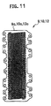
- FIG. 11 is a plan view of a long plate member according to the first embodiment of the present invention.
- FIGS. 12A and 123 show a longitudinal arrangement of the bars according to the first embodiment of the present invention, FIG. 12A being an enlarged plan view of a part of FIG. 11 , FIG. 12B being a cross-sectional view taken along a line B-B.
- FIG. 13 is an enlarged cross-sectional view showing the longitudinal arrangement of the bars according to the first embodiment of the present invention.
- FIGS. 14A and 14B schematically illustrate a process where one of the hair raising bars according to the first embodiment of the present invention is raising a flat lying body hair
- FIG. 14A being a cross-sectional view schematically showing a state where the hair raising portion of the hair raising bar is under the flat lying body hair
- FIG. 14B being a cross-sectional view schematically showing a state where the hair raising portion is raising the flat lying body hair.
- FIG. 15 is a cross sectional view of a bar according to a first modification of the first embodiment of the present invention.
- FIG. 16 is a cross sectional view of a bar according to a second modification of the first embodiment of the present invention.
- FIG. 17 is a cross sectional view of a bar according to a third modification of the first embodiment of the present invention.
- FIG. 18 is a cross sectional view of a bar according to a fourth modification of the first embodiment of the present invention.
- FIG. 19 is a cross sectional view of a bar according to a fifth modification of the first embodiment of the present invention.
- FIG. 20 is a cross sectional view of a bar according to a sixth modification of the first embodiment of the present invention.
- FIG. 21 is a cross sectional view of a bar according to a seventh modification of the first embodiment of the present invention.
- FIGS. 22A and 22B show a longitudinal arrangement of the bars according to the second embodiment of the present invention, FIG. 22A being an enlarged cross-sectional view of a part of a long plate member, FIG. 22B being an enlarged cross-sectional view of a part of an outer blade.
- FIG. 23 is a cross-sectional view schematically showing a state where one of the hair raising bars according to the second embodiment of the present invention is raising a flat lying body hair.
- FIG. 24 is an enlarged plan view of a part of an electric shaver according to a third embodiment of the present invention.
- FIGS. 25A and 25B schematically illustrate a process where a lying body hair is being cut by an inner blade and an outer blade according to the third embodiment of the present invention
- FIG. 25A being a cross-sectional view schematically showing a state where the hair raising portion is raising the lying body hair
- FIG. 25B being a cross-sectional view showing a state where the body hair is cut.
- a front-back direction (a shaving direction) X
- a right-left direction Y the direction that each outer blade extends.
- the vertical direction in a state where a head section is placed with the outer blade facing upward is referred to as a vertical direction Z.
- An electric shaver 1 includes a grip section 2 gripped by a hand and a head section fixed to the grip section 2 as shown in FIG. 1 .
- the grip section 2 includes: a grip body 3 which is made of synthetic resin and incorporates a not-shown battery; and a grip joint portion 4 which is made of synthetic resin and is protruded rearward from the upper surface of the grip body 3 .
- the head section 5 may be attached to the grip section 2 so as to swing in the right-left or front-back direction by providing at least one of a known right-left swinging mechanism and a known front-back swinging mechanism on the upper surface of the grip joint portion 4 .
- the head section 5 includes: a linear head portion 6 which incorporates a not-shown linear motor and is connected to the grip joint portion 4 ; and a blade unit 7 attached to the linear head portion 6 .
- a switch portion 90 configured to turn on and off drive of the linear motor is formed at the grip body 3 .
- the grip body 3 may be provided with a display portion displaying a charging state of the battery and the like.
- the blade unit 7 includes outer blades 8 exposed upward in the head section 5 and inner blades 13 which are provided inside of the outer blades 8 (under the outer blades 8 ) and moved relative to the outer blades 8 .
- This embodiment is provided with four (a plurality of) outer blades: a first net blade 9 , a finishing net blade 10 , a slit blade 11 , and a second net blade 12 , which are arranged side by side in the front-back direction X.
- each of the net blades 9 , 10 , and 12 is curved in an inverted U shape in the front-back direction (the short side direction) so as to be convex up in a side view (when each outer blade is seen in the right-left direction Y). Furthermore, each of the net blades 9 , 10 , and 12 is slightly curved in the right-left direction (the longitudinal direction) Y so as to be convex up in a front view (when each outer blade is seen in the front-back direction X). In this embodiment, the net blades 9 , 10 , and 12 are curved so as to be convex up in the front view but are not necessarily curved.
- a number of blade holes 50 are defined by bars 40 .
- the blade width of the finishing net blade 10 (width in the front-back direction X) is set smaller than blade widths of the first and second net blades 9 and 12 (widths in the front-back direction X).
- the slit blade 11 is curved in a squared U-shape in the front-back direction (the short-side direction) and includes a number of slits (blade holes) drilled from the flat upper wall to the side walls.
- the number of slits are defined by substantially squared U-shaped bars from the flat upper wall to the side walls and a bar extending along the longitudinal direction (the right-left direction) Y at the bottom of each side wall.
- the net blades 9 , 10 , and 12 and the slit blade 11 constituting the outer blades 8 are attached to dedicated outer blade frames 19 , 20 , 22 , and 21 , respectively.
- a skin guard member 20 a is formed in the first net blade 9 side of the outer blade frame 20 .
- the skin guard member 20 a and the slit blade 11 sandwiching the finishing net blade 10 at the front and rear sides effectively prevent the skin 70 from being strongly pressed against the finishing net blade 10 having a small curvature.
- the outer blade frame 19 to which the first net blade 9 is attached, the outer blade frame 20 to which the finishing net blade 10 is attached, the outer blade frame 21 to which the slit blade 11 is attached, and the outer blade frame 22 to which the second net blade 12 is attached are individually engaged with an outer blade frame 18 to form the outer blade cassette 30 .
- the outer blade cassette 30 is attached to the linear head portion 6 .
- the inner blades 13 are dedicatedly provided for the net blades 9 , 10 , and 12 and the slit blade 11 constituting the outer blades 8 .
- inversed U-shape inner blades 14 , 15 , and 17 along the curves of the corresponding net blades 9 , 10 , and 12 are provided, respectively (see FIG. 2 ).
- a squared U-shaped slit inner blade (not-shown) along the curve of the slit blade 11 is provided.
- the inner blades 14 , 15 , and 17 and slit inner blade (not shown) are attached to the aforementioned not-shown linear motor. If the linear motor is driven, the inner blades 14 , 15 , and 17 and the slit inner blade (not shown) are reciprocated in the right-left direction (longitudinal direction) Y.
- the body hair 71 inserted in the blade holes 50 of the net blades 9 , 10 , and 12 and the slits of the slit blade 11 are cut by the net blades 9 , 10 , and 12 and slit blade 11 in cooperation with the inner blades 14 , 15 , and 17 and slit inner blade (not shown).
- the bars 40 include: short-side bars 41 extending in a wave shape in the short-side direction (front-back direction) X; and longitudinal bars 42 extending in the longitudinal direction (right-left direction) Y. These short-side and longitudinal bars 41 and 42 define the blade holes 50 substantially hexagonal in a plan view. These blade holes 50 have sufficient size to allow the body hairs 71 to be inserted therein.
- long-plate members 9 c , 10 c , and 12 c (see FIG. 11 ) including the number of blade holes 50 are curved in an inverted U-shape along the front-back direction (shaving direction) X so as to be convex up and attached to the outer blade frames 19 , 20 , and 22 to form the net blades 9 , 10 , and 12 curved in an inverted U-shape in a side view, respectively.
- top sections 9 a , 10 a , and 12 a positioned at the top have large contact pressure against the skin 70 .
- the outside sections 9 b , 10 b , and 12 b positioned on both sides of the top sections 9 a , 10 a , and 12 a in the short-side direction have small contact pressure against the skin 70 .
- the dashed-dotted line in FIG. 5 indicates a centerline passing through the center of each of the top sections 9 a , 10 a , and 12 a in the short-side direction.
- the longitudinal bars 42 include: longitudinal bars (first bars) 43 each having a cross-sectional shape shown in FIG. 6 ; longitudinal bars (second bars) 44 each having a cross-sectional shape shown in FIG. 7 ; and longitudinal bars (hair raising bars) 45 each having a cross-sectional shape shown in FIG. 8A .
- each of the longitudinal bars (first bar) 43 includes a substantially flat top surface (skin contact surface) 43 a , a flat bottom surface 43 b formed on the inner blade 13 side (the bottom in FIG. 6 ), both side surfaces 43 c and 43 c smoothly connecting the ends of the top surface (skin contact surface) 43 a and the bottom surface 43 in the short-side direction and is formed so as to have a substantially half-barrel shape in a cross section.
- sliding portions 43 e , 43 e are protruded toward the inner blade 13 side.
- the sliding portions 43 e , 43 e are configured to slide on the inner blades 13 so that the body hair 71 is cut by the sliding portions 43 e and the inner blade 13 .
- an end 43 g of an upper portion 43 f of the longitudinal bar (first bar) 43 in the short-side direction is formed to have a semicircular cross section with a curvature radius R 1 so as to reduce damage of the skin 70 .
- the curvature radius R 1 is preferably 10 ⁇ m, for example.
- each longitudinal bar (second bar) 44 includes: a substantially flat top surface (skin contact surface) 44 a which is formed on the skin 70 side (in the upper side of FIG. 7 ) and comes into contact with the skin 70 ; a flat bottom surface 44 b formed on the inner blade 13 side (in the lower side in FIG. 7 ); and both side surfaces 43 c and 43 c smoothly connecting the ends of the top surface (skin contact surface) 44 a and the bottom surface 44 b in the short-side direction.
- the top and bottom surface and the side surfaces form a substantially half-barrel shape in a cross section.
- sliding portions 44 e , 44 e are protruded toward the inner blades 13 side and are configured to slide on the inner blades 13 so that the body hair 71 are cut by the sliding portions 44 e and the inner blades 13 .
- an end 44 g of an upper portion 44 f of the longitudinal bar (second bar) 44 in the short-side direction is formed so as to have a semicircular cross section with a curvature radius R 3 so as to reduce damage of the skin 70 .
- the curvature radius R 3 is preferably set to 10 ⁇ m or more, for example.
- the top surface (skin contact surface) 41 a of each short-side bar 41 is closer to the skin 70 than the top surface 43 a of each longitudinal bar (first bar) 43 .
- the vertical distance between the top surface 43 a of each longitudinal bar (first bar) 43 and the top surface 41 a of each short-side bar 41 is set to L 1 .
- the top surface 41 a of the short-side bar 41 and the top surface 44 a of the longitudinal bar (second bar) 44 form a substantially same plane.
- Vertical distance L 3 between the top surface 41 a of each short-side bar 41 and the top surface 44 a of each longitudinal bar (second bar) 44 is substantially zero.
- each of the longitudinal bars (hair raising bars) 45 is formed so as to have a substantially V-shaped cross section.
- a plate portion 45 a having a substantially plate shape is formed at the center in the short-side direction.
- inclined portions 45 b are provided at the both ends of the plate portion 45 a in the short-side direction.
- the inclined portions 45 b are inclined so as to go upward from the plate portion 45 a toward the both ends in the short-side direction.
- the inclined portions 45 b are tapered so as to narrow from the plate portion 45 a toward the both ends in the short-side direction.
- hair raising portions 45 c to raise the body hair 71 are formed.
- each longitudinal bar (hair raising bar) 45 includes: the hair raising portion 45 c (on the right side of FIG. 14 ) exerting the hair raising operation mainly when the electric shaver is moved one way in the shaving direction (from the left to the right in FIG. 14 ; the direction a); and the hair raising portion 45 c (on the left side of FIG. 14 ) exerting the hair raising operation mainly when the electric shaver is moved in the other way in the shaving direction (from the right to the left in FIG. 14 ; the direction b).
- the plurality of hair raising portions are provided for each hair raising bar facing in different directions so as to exert the hair raising operation when the electric shaver moves at least in two directions.
- the side surfaces 43 c of the longitudinal direction bar (first bar) 43 and the side surfaces 44 c of the longitudinal bar (second bar) 44 also function as hair raising portions to raise the body hair 71 .
- the side surfaces 43 c and 44 c also include the hair raising operation to raise the body hair 71 having small angle from the skin surface, the hair raising portions 45 c can more effectively raise the body hair 71 lying flat than the side surfaces 43 c and 44 c .
- the hair raising portions 45 c have higher hair raising ability to raise the body hair 71 lying flat than that of the side surfaces 43 c and 44 c.
- each longitudinal bar (the hair raising bar) 45 is provided with the hair raising portions 45 c with higher hair raising ability than those of the hair raising portions (the side surfaces 43 c in this embodiment) of the longitudinal bars (the first bars) 43 and the hair raising portions (the side surfaces 44 c in this embodiment) of the longitudinal bars (the second bars) 44 .
- each longitudinal bar (hair raising bar) 45 is defined by the upper flat surface 45 c of the plate portion 45 a , upper inclined surfaces 45 e of the inclined portions 45 c , the bottom surface 45 f of the plate portion 45 a , and the lower inclined surfaces 45 g of the inclined portions 45 c.
- the upper flat surface 45 d and the upper inclined surfaces 45 e correspond to a skin contact surface 45 j coming into the skin 70
- the lower inclined surfaces 45 g correspond to hair introducing surfaces 45 k which introduce the body hair 71 inside the outer blades (toward the inner blades).
- the vertical distance between the ends 45 l of each hair raising portion 45 c and the top surface 41 a of each short-side bar 41 is set to L 2 .
- the raising portions 45 c are arranged with an offset so as to satisfy a relation of L 3 ⁇ L 2 ⁇ L 1 .
- the vertical distance between the upper flat portion 45 d of each longitudinal bar (hair raising portion) 45 and the top surface 41 a of each short-side bar 41 is set to L 4 .
- the upper flat portion 45 d is arranged with an offset so as to satisfy a relation of L 3 ⁇ L 4 ⁇ L 1 .
- each of the ends 45 l of the inclined portions 45 b in the short-side direction is formed so as to have a semicircular cross-section with a curvature radius R 2 .
- the relation of the curvature radii R 1 to R 3 are set to R 2 ⁇ R 1 ⁇ R 3 .
- R 2 is 3 ⁇ m, for example.
- a clearance angle ⁇ between a reference line 60 in the short-side direction (herein after, referred to as a short-side direction reference line 60 ) indicated by a two-dot chain line and each upper inclined surface 45 e is set larger than a clearance angle (0°) between the top surface 43 a of each longitudinal bar (first bar) 43 and the short-side direction reference line 60 and a clearance angle (0°) between the top surface 44 a of each longitudinal bar (second bar) 44 and the short-side direction reference line 60 .
- each longitudinal end 45 m of each longitudinal bar (hair raising bar) 45 extends from the side wall surface 41 b of the short-side bar 41 in the longitudinal direction so as to have a linear cross-section and is gradually curved through a boundary portion 45 o to be connected to a longitudinal center portion 45 n .
- the boundary portion 45 o has a curvature radius of 10 ⁇ m, for example.
- the longitudinal bars 42 include: the longitudinal bars (hair raising bars) 45 each including the hair raising portions 45 c with higher hair raising ability than those of the hair raising portions (corresponding to the side surfaces 43 c and 44 c in this embodiment) of the other bars (longitudinal bars 43 and 44 ); the longitudinal bars (first bars) 43 , in each of which the top surface 44 a is positioned on the inner blade 13 side of the skin contact surface 45 j of each longitudinal bar (hair raising hair) 45 ; and the longitudinal bars (second bars) 44 , in each of which the top surface 43 a is positioned on the skin 70 side of the skin contact surface 45 j of each longitudinal bar (hair raising hair) 45 .
- the longitudinal bars (first bars) 43 are placed in the part of each of the net blades 9 , 10 , and 12 with high contact pressure against the skin 70 (the top sections 9 a , 10 a , and 12 a ), and the longitudinal bars (hair raising bars) 45 are placed in the part with low contact pressure (the outside sections 9 b , 10 b , and 12 b ).
- one of the longitudinal bar (first bar) 43 in which the top surface (skin contact surface) 43 a coming into contact with the skin 70 is positioned on the inner blade 13 side of the skin contact surface 45 j of the longitudinal bar (hair raising bar) 45 , is provided in adjacent to each longitudinal bar (hair raising bar) 45 forwardly in the short-side direction (the front-back direction; the shaving direction) X.
- the longitudinal bars 45 are provided at ends of the outside sections 9 b , 10 b , and 12 b on the top section sides.
- the outside sections 9 b , 10 b , and 12 b extend on both sides of the top sections 9 a , 10 a , and 12 b in the short-side direction X, respectively.
- first bars 43 are provided adjacent to the respective longitudinal bars (hair raising bars) 45 outside thereof in the short-side direction X (on the lower side FIG. 13 ).
- some of the longitudinal bars (second bars) 44 in each of which the top surface (skin contact surface) 44 a coming into contact with the skin 70 is positioned on the skin 70 side of the skin contact surface 45 j of the longitudinal bars (body hair bars) 45 , are individually provided outside thereof in the short-side direction (on the lower side of FIG. 13 ), the longitudinal bars 43 being provided adjacent to the longitudinal bars (body hair bars) 45 .
- the longitudinal bar (body hair bars) 45 , longitudinal bar (first bar) 43 , and longitudinal bar (second bar) 44 are provided, 10 b , and 12 b in this order starting from the top section side as shown in FIG. 13 .
- one of the longitudinal bars (first bars) 43 is provided on the rear side of each longitudinal bar (hair raising bar) 45 in the shaving direction.
- the longitudinal bars (first bars) 43 are placed on both sides of each longitudinal bar (hair raising bar) 45 in the short-side direction.
- each longitudinal bar (body hair bar) 45 is placed on both sides of each longitudinal bar (body hair bar) 45 in the short-side direction as described above, the longitudinal bars (first bars) 43 exist forward of the longitudinal bar (body hair bar) 45 in the shaving direction whichever the outer blades 8 are moved in the short-side direction forward or backward.
- the longitudinal bars (first bars) 43 in each of which the top surface (skin contact surface) coming into contact with the skin 70 is positioned on the inner blade 13 side of the skin contact surface 45 j of the longitudinal bar (body hair bar) 45 , is provided in adjacent to and forward of each longitudinal bar (body hair bar) 45 in the short-side direction (the front-back direction; the shaving direction). Accordingly, there is a large space ahead of the hair raising portion 45 c , so that the skin 70 can be further introduced to the inner blade side 13 .
- the hair raising portions 45 c can be further pressed into the skin 70 , so that the flat lying body hair 71 can be more efficiently raised (see FIG. 14 ).
- FIG. 14 shows an example where the net blades (outer blades) 9 , 10 , and 12 move one way in the shaving direction (from the left to the right in FIG. 14 ; the direction a).
- the net blades (outer blades) 9 , 10 , and 12 move the other way in the shaving direction (from the right to the left in FIG. 14 ; the direction b). In this case, the front and back in the shaving direction are replaced with each other.
- one of the longitudinal bars (first bars) 43 is also placed behind each longitudinal bar (hair raising bar) 45 in the shaving direction.
- the longitudinal bars (first bars) 43 are placed on both sides of each longitudinal bar (body hair bar) 45 .
- the bars 40 include the longitudinal bars (second bars) 44 , in each of which the top surface (skin contact surface) 44 a coming into contact with the skin 70 is positioned on the skin 70 side of the skin contact surface 45 j of each longitudinal bar (hair raising bar) 45 .
- the hair raising portions 45 c can be prevented from being excessively pressed into the skin 70 , thus reducing the influence (damage) on the skin 70 (see FIG. 14 ).
- each short-side bar 41 the top surface (skin contact surface) 41 a coming into contact with the skin 70 is positioned on the skin 70 side of the skin contact surface 45 j of each longitudinal bar (hair raising bar) 45 .
- Each short-side bar 41 therefore corresponds to a second hair raising bar. Accordingly, the longitudinal bars (second bars) 44 and the short-side bars 41 can effectively reduce the influence (damage) on the skin 70 .
- the longitudinal bars (hair raising bars) 45 , the longitudinal bars (first bars) 43 , and the longitudinal bars (second bars) 44 are provided for the net blades (outer blades) 9 , 10 , and 12 , the influence (damage) on the skin 70 is reduced while the performance of introducing the flat lying body hair 71 to the net blades (outer blades) 9 , 10 , and 12 can be increased.
- the longitudinal bars (first bars) 43 are placed in the part of each of the net blades 9 , 10 , and 12 with high contact pressure against the skin 70 (the top sections 9 a , 10 a , and 12 a ).
- the longitudinal bars (hair raising bars) 45 each including the hair raising portions 45 c with higher hair raising ability than that of the side surfaces (hair raising portions) 43 c of the longitudinal bars (first bars) 43 are placed.
- the hair raising ability is increased so as to efficiently raise hair.
- the bars 40 include the longitudinal bars 42 extending in the longitudinal direction of the net blades (outer blades) 9 , 10 , and 12 and the short-side bars 41 extending in the short-side direction intersecting the longitudinal direction, thus forming the net blades (outer blades) 9 , 10 , and 12 into mesh.
- This allows the body hair 71 to be easily inserted into the blade holes 50 , thus providing an effect of facilitating shaving the body hair 71 .
- each of the net blades (outer blades) 9 , 10 , and 12 is curved in an inverted U-shape in a side view.
- the side surfaces (hair raising portions) 43 c are formed at both ends of the longitudinal bars 43 in the short-side direction in the net blades (outer blades) 9 , 10 , and 12 .
- the side surfaces (hair raising portions) 44 c are formed at both ends of the longitudinal bars 44 in the short-side direction in the net blades (outer blades) 9 , 10 , and 12 .
- the hair raising portions 45 c are formed at both ends of the longitudinal bars 45 in the short-side direction in the net blades (outer blades) 9 , 10 , and 12 .
- the body hairs 71 can be therefore raised whichever the electric shaver 1 is moved in the short-side direction forward or backward. This can provide an effect of improving the usability.
- the inclined portions 45 b inclined so as to go up from the plate portion 45 a toward the both ends thereof in the short-side direction are provided for each longitudinal bar (hair raising bar) 45 .
- the inclined portions 45 b are tapered so as to narrow from the plate portion 45 a toward the both ends in the short-side direction.
- the hair raising portions 45 c configured to raise the body hair 71 are formed.
- each longitudinal bar 45 is formed so as to have a substantially liner cross-section, and the inclined portions 45 b are provided for the longitudinal center portion 45 n .
- These longitudinal end 45 m and the longitudinal center portion 45 n are connected by the gradually curved boundary portion 45 o between the longitudinal edge 45 m , and the longitudinal center portion 45 n .
- a bar 40 A according to this modification has a substantially inverted trapezoidal cross-section and is formed by: a substantially flat top surface (skin contact surface) 40 a A which is formed on the skin 70 side (on the upper side in FIG. 15 ) and comes into contact with the skin 70 ; a flat bottom surface 40 b A formed on the inner blade 13 side (on the lower side in FIG. 15 ); and both side surfaces 40 c A and 40 c A smoothly connecting ends of the top surface (skin contact surface) 40 a A and bottom surface 40 b A in the short-side direction.
- a pair of hair raising portions 40 d A and 40 d A are formed at both ends of upper part of the bar 40 A in the short-side direction.
- the top surface (skin contact surface) 40 a A of the first bar needs to be positioned on the inner blade 13 side of the top surface 40 a A of the hair raising bar
- the top surface (skin contact surface) 40 a A of the second bar needs to be positioned on the skin 70 side of the top surface 40 a A of the hair raising bar.
- a taper angle ⁇ between the top surface (skin contact surface) 40 a A of the hair raising bar and each side surface 40 c A needs to be smaller than the taper angle ⁇ between the top surface (skin contact surface) 40 a A and each side surface 40 c A in the first bar and the taper angle ⁇ between the top surface (skin contact surface) 40 a A and the side surface 40 c A in the second bar.
- the taper angle ⁇ of the hair raising portion of the hair raising bar smaller than those of the hair raising portions of the first and second bars, the hair raising ability of the hair raising portion of the hair raising bar can be set higher than those of the hair raising portions of the first and second bars.
- the taper angles ⁇ of the hair raising portions of the first and second bars is 70°, for example, and the taper angles ⁇ of the hair raising portion of the hair raising bar is 20°, for example.
- a bar 40 B according to this modification is formed into a plate shape including: a substantially flat top surface (skin contact surface) 40 a 3 which is formed on the skin 70 side (on the upper side in FIG. 16 ) and comes into contact with the skin 70 and a flat bottom surface 40 b B formed on the inner blade 13 side (on the lower side in FIG. 16 ).
- the both ends of the bar 40 B in the short-side direction constitute semicircular hair raising portions 40 c B and 400 B.
- the top surface (skin contact surface) 40 a B of the first bar needs to be positioned on the inner blade 13 side of the top surface 40 a B of the hair raising bar
- the top surface (skin contact surface) 40 a B of the second bar needs to be positioned on the skin 70 side of the top surface (skin contact surface) 40 a B of the hair raising bar.
- the curvature radius of each hair raising portion 40 c B of the hair raising bar needs to be smaller than the curvature radius of each of the hair raising portions 40 c B of the first and second bars.
- each hair raising portion 40 c B of the hair raising bar By setting the radius curvature of each hair raising portion 40 c B of the hair raising bar smaller than those of the hair raising portions 40 c B of the first and second bars as described above, the hair raising ability of the hair raising portion of the hair raising bar can be set higher than those of the hair raising portions of the first and second bars.
- a bar 40 C according to this modification is defined by a top surface (skin contact surface) 40 a C which is curved convexly toward the skin 70 side (the upper side in FIG. 17 ) and comes into contact with the skin 70 ; a flat bottom surface 40 b C formed on the inner blade 13 side (on the lower side in FIG. 17 ); and both side surfaces 40 c C, 40 c C smoothly connecting ends of the top surface (skin contact surface) 40 a C and bottom surface 40 b C in short-side direction.
- a pair of hair raising portions 40 d C, 40 d C are formed.
- the aforementioned bar 40 C can be used as each of the first, second, and hair raising bars in the same way as that of the first modification.
- a bar 40 D includes a body portion 40 b D having a substantially half-barrel shaped cross section.
- a substantially flat top surface (skin contact surface) 40 a D coming into contact with the skin 70 is formed.
- a pair of hair raising portions 40 c D, 40 c D are formed.
- the aforementioned bar 40 D can be used as each of the first, second, and hair raising bars in the same way as that of the first or second modification.
- a bar 40 E includes a substantially plate-shaped body portion 40 c E having a substantially flat top surface (skin contact surface) 40 a E which is formed on the skin 70 side (in the upper side of FIG. 19 ) and comes into contact with the skin 70 .
- a protrusion 40 b E extending downward is formed.
- a pair of hair raising portions 40 d E, 40 d E are formed.
- the aforementioned bar 40 E can be used as each of the first, second, and hair raising bars in the same way as that of the second modification.
- a bar 40 F according to this modification has a substantially T-shaped cross section.
- the bar 40 F includes a substantially plate-shaped body portion 40 b F having a substantially flat top surface (skin contact surface) 40 a F which is formed on the skin 70 side (in the upper side of FIG. 20 ) and comes into contact with the skin 70 .
- a protrusion 40 c F extending downward is formed.
- a pair of hair raising portions 40 d F, 40 d F are formed.
- the aforementioned bar 40 F can be used as each of the first, second, and hair raising bars in the same way as that of the second modification.
- a bar 40 G according to this modification has a cross section of a substantially H shape turned sideways.
- the bar 40 G includes a substantially plate-shaped body portion 40 b G having a substantially flat top surface (skin contact surface) 40 a G which is formed on the skin 70 side (in the upper side of FIG. 20 ) and comes into contact with the skin 70 .
- a protrusion 40 c G extending downward is formed.
- extensions 40 d G, 40 d G having triangular cross sections and extending toward the both ends in the short-side direction are formed.
- a pair of hair raising portions 40 e G, 40 e G are formed.
- the aforementioned bar 40 G can be used as each of the first, second, and hair raising bars in the same way as that of the second modification.
- net blades 9 H, 10 H, and 12 H according to a second embodiment have basically substantially the same configurations as those of the net blades 9 , 10 , and 12 according to the first embodiment.
- the net blades 9 H, 10 H, and 12 H are respectively composed of long-plate members 9 c H, 10 c H, and 12 c H including a number of blade holes 50 defined by the short-side bars 41 and longitudinal bars 42 (see FIG. 22A ).
- Each of the long-plate members 9 c H, 10 c H, and 12 c H is curved in an inverted U shape in the front-back direction (shaving direction) X convexly upward.
- the longitudinal bars 42 include the longitudinal bars (hair raising bar) 45 , the longitudinal bars (first bar) 43 , and the longitudinal bars (second bars) 44 .
- Each of the longitudinal bar 45 includes the hair raising portion 45 c having higher hair raising ability than that of the hair raising portions (in this embodiment, the hair raising portions correspond to the side surfaces 43 c and 44 c ) of the other bars (the longitudinal bars 43 and 44 ).
- Each longitudinal bar 43 includes the top surface 43 a positioned on the inner blade 13 side of the skin contact surface 45 j of each longitudinal bar (hair raising bar) 45 .
- Each longitudinal bar 44 includes the top surface 44 a positioned on the skin 70 side of the skin contact surface 45 j of each longitudinal bar (hair raising bar) 45 .
- the longitudinal bars (first bars) 43 in which the top surface (skin contact surface) 43 a coming into contact with the skin 70 is positioned on the inner blade 13 side of the skin contact surfaces 45 j of each longitudinal bar (hair raising bar) 45 , are individually provided adjacent to and forward of the respective longitudinal bars (hair raising bars) 45 in the short-side direction (the front-back direction; the shaving direction) X.
- the longitudinal bars (hair raising bars) 45 are provided at (inner) ends of the outside sections 9 b H, 10 b H, and 12 b H on the top section side, the outside sections 9 b H, 10 b H, and 12 b H extending on both sides of the top sections 9 a H, 10 a H, and 12 a H in the short-side direction X, respectively.
- the longitudinal bars (first bars) 43 are provided adjacent to and outside of the respective longitudinal bars (hair raising bars) 45 in the short-side direction (the front-back direction; the shaving direction) X.
- longitudinal bars (second bars) 44 in each of which the top surface (skin contact surface) 44 a coming into contact with the skin 70 is positioned on the skin 70 side of the skin contact surfaces 45 j of each longitudinal bar (hair raising bar) 45 , are provided adjacent to and outside of the respective longitudinal bars (first bars) 43 , which are provided adjacent to the longitudinal bars (hair raising bars) 45 , in the short-side direction (the front-back direction: the shaving direction) X.
- some of the longitudinal bars (second bars) 44 are provided in a part of each of the net blades 9 H, 10 H, and 12 H with high contact pressure against the skin 70 (the top sections 9 a H, 10 a H, and 12 a H), and the longitudinal bars (hair raising bars) 45 are provided in parts with low contact pressure (the outside sections 9 b H, 10 b H, and 12 b H).
- the longitudinal bars (second bars) 44 are provided adjacent to and rearward of the respective longitudinal bars (hair raising bars) 45 in the shaving direction. As shown in FIG. 22 , the longitudinal bars (second bars) 44 are provided at both ends of the top sections 9 a H, 10 a H, and 12 a H in the short-side direction (the front-back direction; shaving direction).
- each of the longitudinal bars (hair raising bars) 45 is provided between one of the longitudinal bars (first bars) 43 and one of the longitudinal bars (second bars) 44 .
- the hair raising portions 45 c can be further prevented from being excessively pressed into the skin 70 . It is therefore possible to effectively reduce the influence (damage) of the hair raising portions 45 c on the skin 70 .
- the longitudinal bars (second bars) 44 are provided adjacent to and rearward of the respective longitudinal bars (hair raising bars) 45 in the shaving direction. Accordingly, when the electric shaver 1 is in use, the hair raising portions 45 c can be further pressed into the skin 70 , so that the flat lying body hair 71 can be raised more efficiently.
- An electric shaver 1 I according to the third embodiment differs from the first embodiment in including an inner blade 13 I composed of a rotary blade.
- the electric shaver 1 I includes an outer blade 8 I and the inner blade 13 I which is provided inside of the outer blade 8 I (under the outer blade 8 I) and move relative to the outer blade 8 I. These outer blade 8 I and inner blade 13 I are both circular.
- the inner blade 13 I rotates in a rotation direction (a direction b) relative to the outer blade 8 I fixed to the body.
- the body hair 71 inserted into one of the blade holes 50 of the outer blade 81 is cut by the outer blade SI in cooperation with the inner blade 13 I.
- the lot of blade holes 50 each having a substantially rectangular shape long in the radial direction are provided in a radial fashion.
- the blade holes 50 are defined by a number of bars 40 I extending in a radial fashion.
- the bars 40 I include first bars 43 I and hair raising bars 45 .
- Each of the hair raising bars 45 I is defined by: a substantially flat top surface (skin contact surface) 45 a I which is formed on the skin 70 side (on the upper side in FIG. 25 ) and comes into contact with the skin 70 ; a flat bottom surface 45 b I formed on the inner blade 13 I side (on the lower side in FIG. 25 ); and both side surfaces 45 c I, 45 c I smoothly connecting the ends of the top surface (skin contact surface) 45 a I and bottom surface 45 b I.
- a hair raising portion 45 d I protruding forward in the shaving direction (the rotation direction of the inner blade 13 I; the direction b in this embodiment) is formed.
- each of the first bars 43 I is formed to have a substantially right-angled trapezoidal cross-section which is defined by a substantially flat top surface (skin contact surface) 43 a I which is formed on the skin 70 side (on the upper side in FIG. 25 ) and comes into contact with the skin 70 ; a flat bottom surface 43 b I formed on the inner blade 13 I side (on the lower side in FIG.
- the side surface 43 d I corresponds to the hair raising portion.
- This side surface 43 d I is designed so as to have a lower hair raising ability than that of the hair raising portion 45 d I.
- the top surface (skin contact surface) 45 a I of the hair raising bar 45 I is protruded outward by h from the top surface (skin contact surface) 43 a I of the first bar 43 a I.
- the top surface (skin contact surface) 43 a I of the first bar 43 a I is therefore positioned on the inner blade 13 I side of the hair raising portion 45 d I of the hair raising bar 45 I.
- the first bar 43 a I in which the top surface (skin contact surface) 43 a I is positioned on the inner blade 13 I side of the hair raising portion 45 d I of the hair raising bar 45 I, is provided adjacent to and forward of each hair raising bar 45 I in the shaving direction (the direction b).
- the first and second embodiments show the example where some bars having a substantially equal hair raising ability are provided in each top section.
- the hair raising portions of the bars in each top section may be arranged in ascending order of the hair raising ability starting from the center in the right-left direction toward each end.
- each of the first, second, and hair raising bars can be composed of a bar of a shape arbitrarily selected from various shapes including the shapes shown in the embodiments and modification. If the first and second bars are composed of bars of a same shape, the first and second bars need to be positioned with a vertical offset (on the skin side and on the inner blade side).
- the first and second embodiments include four outer blades arranged side by side.
- the number of the outer blades may be 1 to 3 or more than 4.
- each of the three net blades is provided with the hair raising bars.
- the hair raising bars only needs to be provided for at least any one of the outer blades including the slit blade.
- the outer blades are provided for the head section fixed to the grip section.
- the outer blades may be provided for the grip section.
- the single circular outer blade is provided.
- the present invention is not limited to this and can be applied to an electric shaver provided with two or more circular outer blades.
Landscapes
- Engineering & Computer Science (AREA)
- Manufacturing & Machinery (AREA)
- Life Sciences & Earth Sciences (AREA)
- Forests & Forestry (AREA)
- Mechanical Engineering (AREA)
- Dry Shavers And Clippers (AREA)
Applications Claiming Priority (2)
| Application Number | Priority Date | Filing Date | Title |
|---|---|---|---|
| JP2010-072274 | 2010-03-26 | ||
| JP2010072274A JP4951083B2 (ja) | 2010-03-26 | 2010-03-26 | 電気かみそり |
Publications (2)
| Publication Number | Publication Date |
|---|---|
| US20110232097A1 US20110232097A1 (en) | 2011-09-29 |
| US8925205B2 true US8925205B2 (en) | 2015-01-06 |
Family
ID=44148689
Family Applications (1)
| Application Number | Title | Priority Date | Filing Date |
|---|---|---|---|
| US13/049,138 Active 2033-08-10 US8925205B2 (en) | 2010-03-26 | 2011-03-16 | Electric shaver |
Country Status (4)
| Country | Link |
|---|---|
| US (1) | US8925205B2 (zh) |
| EP (1) | EP2371496B1 (zh) |
| JP (1) | JP4951083B2 (zh) |
| CN (1) | CN102198667B (zh) |
Cited By (2)
| Publication number | Priority date | Publication date | Assignee | Title |
|---|---|---|---|---|
| US20160089799A1 (en) * | 2014-09-30 | 2016-03-31 | Izumi Products Company | Rotary electric shaver |
| US20180243930A1 (en) * | 2017-02-24 | 2018-08-30 | Panasonic Intellectual Property Management Co., Ltd. | Method of producing outer blade for hair cutting device, outer blade for hair cutting device and hair cutting device |
Families Citing this family (2)
| Publication number | Priority date | Publication date | Assignee | Title |
|---|---|---|---|---|
| JP4955711B2 (ja) | 2009-01-15 | 2012-06-20 | パナソニック株式会社 | 電気かみそり |
| JP6471984B2 (ja) * | 2016-06-16 | 2019-02-20 | パナソニックIpマネジメント株式会社 | 電気かみそり、当該電気かみそりで用いられる外刃 |
Citations (16)
| Publication number | Priority date | Publication date | Assignee | Title |
|---|---|---|---|---|
| FR743144A (zh) | 1933-03-23 | |||
| US2281841A (en) | 1938-07-16 | 1942-05-05 | Fred E Sudlow | Razor |
| US2877548A (en) * | 1954-04-02 | 1959-03-17 | Philips Corp | Dry shaver shear plate and cutter construction |
| DE1949521A1 (de) | 1969-10-01 | 1971-04-08 | Krups Fa Robert | Trockenrasiergeraet |
| US4035914A (en) | 1974-11-25 | 1977-07-19 | Braun Aktiengesellschaft | Shear foil for a dry shaver |
| JPS58117264A (ja) | 1981-12-29 | 1983-07-12 | Shoei Kagaku Kogyo Kk | 抵抗塗料 |
| US4589205A (en) * | 1983-03-28 | 1986-05-20 | Matsushita Electric Works, Ltd. | Inner cutter for electric shavers |
| EP0279088A1 (en) | 1987-01-27 | 1988-08-24 | Koninklijke Philips Electronics N.V. | Cutting unit for a shaving apparatus |
| JPH0383548A (ja) | 1989-08-28 | 1991-04-09 | Maruzen Kasei Co Ltd | スーパーオキサイド消去剤、飲食物および化粧料 |
| JPH03267090A (ja) | 1990-03-17 | 1991-11-27 | Kyushu Hitachi Maxell Ltd | 電気かみそり等の外刃 |
| US5119558A (en) | 1989-11-14 | 1992-06-09 | U.S. Philips Corp. | Shaving apparatus |
| CN1143558A (zh) | 1995-05-19 | 1997-02-26 | 松下电工株式会社 | 电动剃须刀刀具的组合 |
| US5867908A (en) * | 1996-05-31 | 1999-02-09 | U.S. Philips Corporation | Shaving apparatus |
| JP2002066169A (ja) | 2000-08-28 | 2002-03-05 | Matsushita Electric Works Ltd | 電気かみそりの外刃 |
| EP1930137A1 (en) | 2006-12-08 | 2008-06-11 | Matsushita Electric Works, Ltd. | Shaving foil for a dry shaver |
| US20110179648A1 (en) | 2010-01-22 | 2011-07-28 | Panasonic Electric Works Co., Ltd. | Electric shaver |
Family Cites Families (8)
| Publication number | Priority date | Publication date | Assignee | Title |
|---|---|---|---|---|
| US134523A (en) * | 1873-01-07 | Improvement in match-safes | ||
| JPS5519155A (en) * | 1978-07-28 | 1980-02-09 | Matsushita Electric Works Ltd | Outer edge of electric razor |
| JPS5652088A (en) * | 1979-10-03 | 1981-05-09 | Matsushita Electric Works Ltd | Outer edge for electric razor |
| JPS57196992A (en) * | 1981-05-29 | 1982-12-03 | Hiroyuki Nagai | Outer blade of electric razor |
| JPS58117264U (ja) * | 1982-02-05 | 1983-08-10 | 三洋電機株式会社 | 電気かみそりの外刃 |
| JPS59146689A (ja) * | 1983-02-12 | 1984-08-22 | 九州日立マクセル株式会社 | 電気かみそりの外刃 |
| CN200970785Y (zh) * | 2006-11-21 | 2007-11-07 | 童志荣 | 剃须刀网罩 |
| CN201161397Y (zh) * | 2008-01-09 | 2008-12-10 | 游图明 | 电动剃须刀的网罩 |
-
2010
- 2010-03-26 JP JP2010072274A patent/JP4951083B2/ja active Active
-
2011
- 2011-03-16 US US13/049,138 patent/US8925205B2/en active Active
- 2011-03-16 CN CN 201110069609 patent/CN102198667B/zh active Active
- 2011-03-17 EP EP20110158577 patent/EP2371496B1/en active Active
Patent Citations (20)
| Publication number | Priority date | Publication date | Assignee | Title |
|---|---|---|---|---|
| FR743144A (zh) | 1933-03-23 | |||
| US2281841A (en) | 1938-07-16 | 1942-05-05 | Fred E Sudlow | Razor |
| US2877548A (en) * | 1954-04-02 | 1959-03-17 | Philips Corp | Dry shaver shear plate and cutter construction |
| DE1949521A1 (de) | 1969-10-01 | 1971-04-08 | Krups Fa Robert | Trockenrasiergeraet |
| US4035914A (en) | 1974-11-25 | 1977-07-19 | Braun Aktiengesellschaft | Shear foil for a dry shaver |
| JPS58117264A (ja) | 1981-12-29 | 1983-07-12 | Shoei Kagaku Kogyo Kk | 抵抗塗料 |
| US4589205A (en) * | 1983-03-28 | 1986-05-20 | Matsushita Electric Works, Ltd. | Inner cutter for electric shavers |
| EP0279088A1 (en) | 1987-01-27 | 1988-08-24 | Koninklijke Philips Electronics N.V. | Cutting unit for a shaving apparatus |
| US4998352A (en) | 1987-01-27 | 1991-03-12 | U.S. Philips Corp. | Cutting unit for a shaving apparatus |
| JPH0383548A (ja) | 1989-08-28 | 1991-04-09 | Maruzen Kasei Co Ltd | スーパーオキサイド消去剤、飲食物および化粧料 |
| US5119558A (en) | 1989-11-14 | 1992-06-09 | U.S. Philips Corp. | Shaving apparatus |
| JPH03267090A (ja) | 1990-03-17 | 1991-11-27 | Kyushu Hitachi Maxell Ltd | 電気かみそり等の外刃 |
| CN1143558A (zh) | 1995-05-19 | 1997-02-26 | 松下电工株式会社 | 电动剃须刀刀具的组合 |
| US5857260A (en) | 1995-05-19 | 1999-01-12 | Matsushita Electric Works, Ltd. | Cutter combination for an electric shaver |
| US5867908A (en) * | 1996-05-31 | 1999-02-09 | U.S. Philips Corporation | Shaving apparatus |
| JP2002066169A (ja) | 2000-08-28 | 2002-03-05 | Matsushita Electric Works Ltd | 電気かみそりの外刃 |
| EP1930137A1 (en) | 2006-12-08 | 2008-06-11 | Matsushita Electric Works, Ltd. | Shaving foil for a dry shaver |
| US20080134523A1 (en) | 2006-12-08 | 2008-06-12 | Matsushita Electric Works, Ltd. | Shaving foil for a dry shaver |
| US20110179648A1 (en) | 2010-01-22 | 2011-07-28 | Panasonic Electric Works Co., Ltd. | Electric shaver |
| CN102166757A (zh) | 2010-01-22 | 2011-08-31 | 松下电工株式会社 | 电剃刀 |
Non-Patent Citations (4)
| Title |
|---|
| China Office action, dated Feb. 27, 2013 along with an english translation thereof. |
| European Search Report on Jul. 6, 2011. |
| U.S. Appl. No. 13/009,226 to Shigetoshi Sakon et al., filed Jan. 19, 2011. |
| U.S. Appl. No. 13/049,369 to Noboru Kobayashi et al., filed Mar. 16, 2011. |
Cited By (3)
| Publication number | Priority date | Publication date | Assignee | Title |
|---|---|---|---|---|
| US20160089799A1 (en) * | 2014-09-30 | 2016-03-31 | Izumi Products Company | Rotary electric shaver |
| US20180243930A1 (en) * | 2017-02-24 | 2018-08-30 | Panasonic Intellectual Property Management Co., Ltd. | Method of producing outer blade for hair cutting device, outer blade for hair cutting device and hair cutting device |
| US10836058B2 (en) * | 2017-02-24 | 2020-11-17 | Panasonic Intellectual Property Management Co., Ltd. | Method of producing an outer blade for a hair cutting device |
Also Published As
| Publication number | Publication date |
|---|---|
| CN102198667B (zh) | 2013-08-21 |
| US20110232097A1 (en) | 2011-09-29 |
| JP4951083B2 (ja) | 2012-06-13 |
| EP2371496B1 (en) | 2014-01-15 |
| CN102198667A (zh) | 2011-09-28 |
| JP2011200551A (ja) | 2011-10-13 |
| EP2371496A1 (en) | 2011-10-05 |
Similar Documents
| Publication | Publication Date | Title |
|---|---|---|
| US9248578B2 (en) | Electric Shaver | |
| US8925205B2 (en) | Electric shaver | |
| US20100077617A1 (en) | Razors and razor cartridges with a decreased total interblade span | |
| US20230150158A1 (en) | Shaving razor cartridge | |
| JP5406769B2 (ja) | 電気かみそり | |
| EP2939802B1 (en) | Hair clipper blade, and hair clipper with hair clipper blade | |
| EP1479488B1 (en) | Cutter | |
| GB2443735A (en) | Hair clipper with angled teeth | |
| EP2554341B1 (en) | Electric shaver | |
| US20180015621A1 (en) | Inner blade of rotary electric shaver | |
| EP2554338B1 (en) | Electric shaver | |
| US20240157590A1 (en) | Wet shave razor cartridge having blade slots | |
| EP2554339B1 (en) | Electric shaver | |
| JP5491920B2 (ja) | 電気かみそり | |
| EP3900897A1 (en) | Razor head with improved guard bar | |
| JP2011147646A (ja) | 電気かみそり | |
| JP2001038071A (ja) | 電気かみそり | |
| CN201669722U (zh) | 电动剃须刀的外刀 | |
| JP2011200488A (ja) | 電気かみそり | |
| JP2011200486A (ja) | 電気かみそり | |
| JPS5937987B2 (ja) | 往復式電気かみそりの刃の構造 |
Legal Events
| Date | Code | Title | Description |
|---|---|---|---|
| AS | Assignment |
Owner name: PANASONIC ELECTRIC WORKS CO., LTD., JAPAN Free format text: ASSIGNMENT OF ASSIGNORS INTEREST;ASSIGNORS:IWASAKI, JYUZAEMON;SHIMIZU, HIROAKI;KOBAYASHI, NOBORU;AND OTHERS;SIGNING DATES FROM 20110209 TO 20110210;REEL/FRAME:025968/0034 |
|
| AS | Assignment |
Owner name: PANASONIC CORPORATION, JAPAN Free format text: MERGER;ASSIGNOR:PANASONIC ELECTRIC WORKS CO.,LTD.,;REEL/FRAME:027697/0525 Effective date: 20120101 |
|
| AS | Assignment |
Owner name: PANASONIC INTELLECTUAL PROPERTY MANAGEMENT CO., LTD., JAPAN Free format text: ASSIGNMENT OF ASSIGNORS INTEREST;ASSIGNOR:PANASONIC CORPORATION;REEL/FRAME:034194/0143 Effective date: 20141110 Owner name: PANASONIC INTELLECTUAL PROPERTY MANAGEMENT CO., LT Free format text: ASSIGNMENT OF ASSIGNORS INTEREST;ASSIGNOR:PANASONIC CORPORATION;REEL/FRAME:034194/0143 Effective date: 20141110 |
|
| STCF | Information on status: patent grant |
Free format text: PATENTED CASE |
|
| FEPP | Fee payment procedure |
Free format text: PAYOR NUMBER ASSIGNED (ORIGINAL EVENT CODE: ASPN); ENTITY STATUS OF PATENT OWNER: LARGE ENTITY |
|
| MAFP | Maintenance fee payment |
Free format text: PAYMENT OF MAINTENANCE FEE, 4TH YEAR, LARGE ENTITY (ORIGINAL EVENT CODE: M1551) Year of fee payment: 4 |
|
| AS | Assignment |
Owner name: PANASONIC INTELLECTUAL PROPERTY MANAGEMENT CO., LTD., JAPAN Free format text: CORRECTIVE ASSIGNMENT TO CORRECT THE ERRONEOUSLY FILED APPLICATION NUMBERS 13/384239, 13/498734, 14/116681 AND 14/301144 PREVIOUSLY RECORDED ON REEL 034194 FRAME 0143. ASSIGNOR(S) HEREBY CONFIRMS THE ASSIGNMENT;ASSIGNOR:PANASONIC CORPORATION;REEL/FRAME:056788/0362 Effective date: 20141110 |
|
| MAFP | Maintenance fee payment |
Free format text: PAYMENT OF MAINTENANCE FEE, 8TH YEAR, LARGE ENTITY (ORIGINAL EVENT CODE: M1552); ENTITY STATUS OF PATENT OWNER: LARGE ENTITY Year of fee payment: 8 |