US8860677B2 - Operating unit, medical device and method for operating said unit - Google Patents
Operating unit, medical device and method for operating said unit Download PDFInfo
- Publication number
- US8860677B2 US8860677B2 US13/389,877 US201013389877A US8860677B2 US 8860677 B2 US8860677 B2 US 8860677B2 US 201013389877 A US201013389877 A US 201013389877A US 8860677 B2 US8860677 B2 US 8860677B2
- Authority
- US
- United States
- Prior art keywords
- input field
- operating unit
- signal
- display
- touch
- Prior art date
- Legal status (The legal status is an assumption and is not a legal conclusion. Google has not performed a legal analysis and makes no representation as to the accuracy of the status listed.)
- Active, expires
Links
- 238000000034 method Methods 0.000 title claims description 9
- 230000009471 action Effects 0.000 claims description 21
- 230000003213 activating effect Effects 0.000 claims description 5
- 230000008569 process Effects 0.000 claims description 2
- 230000001681 protective effect Effects 0.000 description 7
- 230000007547 defect Effects 0.000 description 5
- 239000004973 liquid crystal related substance Substances 0.000 description 4
- 230000002411 adverse Effects 0.000 description 3
- 238000002583 angiography Methods 0.000 description 3
- 230000000694 effects Effects 0.000 description 3
- 239000011521 glass Substances 0.000 description 3
- 239000002313 adhesive film Substances 0.000 description 2
- 230000008901 benefit Effects 0.000 description 2
- 230000008859 change Effects 0.000 description 2
- 238000010276 construction Methods 0.000 description 2
- 230000006378 damage Effects 0.000 description 2
- 238000001514 detection method Methods 0.000 description 2
- 238000003745 diagnosis Methods 0.000 description 2
- 238000005516 engineering process Methods 0.000 description 2
- 239000010408 film Substances 0.000 description 2
- 238000003384 imaging method Methods 0.000 description 2
- 241000218691 Cupressaceae Species 0.000 description 1
- 208000027418 Wounds and injury Diseases 0.000 description 1
- 230000004913 activation Effects 0.000 description 1
- 239000004020 conductor Substances 0.000 description 1
- 238000010586 diagram Methods 0.000 description 1
- 238000011156 evaluation Methods 0.000 description 1
- AMGQUBHHOARCQH-UHFFFAOYSA-N indium;oxotin Chemical compound [In].[Sn]=O AMGQUBHHOARCQH-UHFFFAOYSA-N 0.000 description 1
- 208000014674 injury Diseases 0.000 description 1
- 239000011159 matrix material Substances 0.000 description 1
- 230000003287 optical effect Effects 0.000 description 1
- 229920003023 plastic Polymers 0.000 description 1
- 230000005855 radiation Effects 0.000 description 1
- 238000001959 radiotherapy Methods 0.000 description 1
- 230000003068 static effect Effects 0.000 description 1
Images


Classifications
-
- G—PHYSICS
- G06—COMPUTING; CALCULATING OR COUNTING
- G06F—ELECTRIC DIGITAL DATA PROCESSING
- G06F3/00—Input arrangements for transferring data to be processed into a form capable of being handled by the computer; Output arrangements for transferring data from processing unit to output unit, e.g. interface arrangements
- G06F3/01—Input arrangements or combined input and output arrangements for interaction between user and computer
- G06F3/03—Arrangements for converting the position or the displacement of a member into a coded form
- G06F3/041—Digitisers, e.g. for touch screens or touch pads, characterised by the transducing means
-
- G—PHYSICS
- G06—COMPUTING; CALCULATING OR COUNTING
- G06F—ELECTRIC DIGITAL DATA PROCESSING
- G06F3/00—Input arrangements for transferring data to be processed into a form capable of being handled by the computer; Output arrangements for transferring data from processing unit to output unit, e.g. interface arrangements
- G06F3/01—Input arrangements or combined input and output arrangements for interaction between user and computer
- G06F3/016—Input arrangements with force or tactile feedback as computer generated output to the user
-
- A—HUMAN NECESSITIES
- A61—MEDICAL OR VETERINARY SCIENCE; HYGIENE
- A61B—DIAGNOSIS; SURGERY; IDENTIFICATION
- A61B6/00—Apparatus or devices for radiation diagnosis; Apparatus or devices for radiation diagnosis combined with radiation therapy equipment
- A61B6/44—Constructional features of apparatus for radiation diagnosis
- A61B6/4429—Constructional features of apparatus for radiation diagnosis related to the mounting of source units and detector units
- A61B6/4435—Constructional features of apparatus for radiation diagnosis related to the mounting of source units and detector units the source unit and the detector unit being coupled by a rigid structure
- A61B6/4441—Constructional features of apparatus for radiation diagnosis related to the mounting of source units and detector units the source unit and the detector unit being coupled by a rigid structure the rigid structure being a C-arm or U-arm
Definitions
- the invention relates to an operating unit comprising at least one display, at least one transparent, touch-sensitive first input field and at least one transparent, touch-sensitive second input field.
- the invention further relates to a medical device with such an operating unit as well is to a method for performing a safety-relevant action by means of such a medical device.
- a safety-relevant action of the devices is to be seen here for example as an action such as one in which a patient or the operating personnel of the device can come to harm indirectly or directly.
- a movable component of a medical device to be controlled is for example the C-arm which serves as a carrier for imaging components, for X-ray devices for example.
- a hardware error does not lead to incorrect behavior of the movable components. In the worst case the patient can be seriously injured by an inadvertent, uncontrolled or automatic movement of such a movable component.
- Such a functional unit would for example be a detector system or a radiation collimator, wherein an inadvertent repositioning of imaging components could prevent use of image data obtained. The examination would therefore have to be repeated and the patient subjected to renewed irradiation for example.
- a further functional unit would be provided for example by an on switch for x-radiation, wherein incorrect operation can likewise cause injury to a patient.
- touch-sensitive input fields which are also known by the names touchscreen touchpad, sensor screen and the like. These involve an operating unit for a processing unit in which, by touching selected areas of the screen, a program sequence on the processing unit can be influenced.
- the image in this case can be generated either dynamically by means of displays, monitors or via a projection or alternatively also by a static, for example printed, image.
- Such an input field can have a single or a plurality of touch-sensitive areas able to be actuated independently of one another.
- a touchscreen is known from U.S. Pat. No. 6,504,530, which has a number of touch-sensitive input fields. These can for example be used in combination with a liquid crystal display or a cathode-ray tube to generate image information to be selected by touch.
- a touch which is detected by means of a first touch-sensitive input field, can be confirmed by a second touch-sensitive input field, which preferably is of another type or operates in a different way. Incorrect operation or unintentional operation is largely prevented by this.
- touch-sensitive input fields have not previously been used, since these do not fulfill the requirements for fault tolerance and/or sufficient haptic feedback.
- the object of the invention is thus to provide an improved operating unit, especially for medical devices, comprising at least one touch-sensitive input field.
- an operating unit comprising at least one display, at least one transparent, touch-sensitive first input field and at least one transparent, touch-sensitive second input field, wherein the least one second input field is disposed between the least one display in the at least one first input field, as well as at least one device which provides a haptically perceivable feedback after successful operation of the operating unit.
- the at least one display is visible through the at least one first input field and the at least one second input field.
- the display involved is preferably a liquid crystal display, especially an active matrix display, an OLED display or similar.
- the actuation of the at least one first input field and of the at least one second input field can be interrogated simultaneously in order to carry out a plausibility check on the operating action undertaken. If the operating unit is actuated successfully, wherein the at least one first operating field and the at least one second operating field have been actuated simultaneously, the operator is provided by the device with a unique haptic feedback about the success of the operating action.
- the touch-sensitive input fields form redundant systems in this case, which make it possible to check the operability of the other system in each case.
- the simultaneous presence of a touch the at least one first input field and the actuation of a second input field lying behind it means that there is a high probability that the operator has performed an intentional operating action, which can consequently be implemented.
- a defect in the area of an input field is uniquely identifiable from the fact that in this case a simultaneous operating action of both systems is not present.
- the inventive operating unit can be used very flexibly since there can be almost any arrangement on a device.
- the operating unit makes barely any demands on the place of use, the mounting location, the available lighting conditions, etc.
- the display can be used, at times when an actuation of the operating unit is not necessary or required, to display data and/or information and/or pictures which are helpful to the operator.
- an online display of examination results or the like can be shown on the display.
- the at least one first input field and the at least one second input field are to involve different types of input field.
- the first and second input field are to be selected so that these fields do not influence each other.
- a capacitive input field can be selected for a first input field and a resistive input field for a second input field.
- a passive film for example made of glass or transparent plastic, with electrodes as sensors which consist of transparent electrically-conductive Indium-Tin Oxide (ITO).
- ITO Indium-Tin Oxide
- other transparent, electrically-conductive materials are also able to be used as electrodes.
- a resistive second input field preferably detects the exact coordinates of the operator's touch, the same resolution is not an absolute requirement for the capacitive first input field. This can likewise deliver coordinates to specify the touch position but can also simply consist of individual surfaces which embody capacitive keys. Such a combination of a capacitive first input field and a resistive second input field ensures that any possibility of the fields influencing one another is excluded.
- the at least one first input field is arranged on the at least one second input field to cover the same area.
- this does not exclude a number of transparent films, adhesive films, glass films or the like and to other transparent combinations thereof being able to be located between a first input field and a second input field.
- the at least one first input field and the at least one second input field are arranged on the display to cover the same area as the latter.
- this does not exclude a number of transparent films, adhesive films, glass films or the like, as well as transparent combinations thereof being able to be located between a second input field and the display.
- the display has a front side facing towards an operator and for the at least one first input field and the at least one second input field to at least partly cover this front side.
- the at least one first input field covers the front side of the display completely.
- the at least one device which provides a haptically perceivable feedback after the operating unit has been successfully operated is preferably connected to a rear side of the at least one display facing away from the user and/or to a carrier of the display.
- the device should generate a vibration, pulsing or shaking of at least an area of the operating unit at which the operation was just carried out perceivable to an operator of the operating unit.
- the haptic feedback is in particular embodied so strongly that a user notices it despite wearing gloves or other protective coverings.
- the at least one device which provides a haptically perceivable feedback after the operating unit has been operated is formed by a vibration motor.
- warning or status indicators which are generated by different haptically perceivable signals output by the device are also transmitted to a user via the haptic feedback.
- an operating unit by means of which an operator for example controls a positioning of a component, reaching and end stop for a movement of the component, an action currently being performed or the threat of a collision between the component and another component if the selected movement is continued can be indicated by output of a respective modified haptically perceivable signal.
- the device can be configured for example to generate different haptically perceivable vibration patterns which are assigned to specific states of the device to be operated and which inform the operator or generate an alarm without the latter having to visually read off corresponding information from the display or other device indicators.
- the at least one first input field can be located directly on the side of the operating unit facing towards the user. This can however equally well be covered by a transparent protective film. This protective film should however not adversely affect the functioning of the at least one first input field and of the at least one second input field.
- a person skilled in the art is readily able to establish electrical contact between a display, a first and second input field and also a device which handles haptic feedback.
- a medical device which is equipped with a least one inventive operating unit has proven especially useful.
- the medical device can for example be a magnetic resonance tomograph, a conventional X-ray device, specifically also an interventional or cardiological angiography system, a computer tomograph or a radiation therapy device.
- the inventive operating unit is however also suitable for other machines or systems in which increased safety requirements apply, such as building machines, robots and the like.
- a medical device with at least one component which is able to be positioned by means of a positioning device, wherein by means of the at least one operating unit an input of a required position of the at least one component and a corresponding activation of the positioning device for adjusting the required position is able to be effected.
- a movement of the component can be put in train by briefly touching the operating unit but also carried out during the continued touching action.
- the medical device preferably comprises at least one processing unit which is configured to receive at least one first signal able to be generated when the at least one first input field is touched and to receive at least one second signal able to be generated when the at least one second input field, which is located in the direction of touch behind the at least one first input field, is touched simultaneously, to process said signal and only in the event that the at least one first signal and the at least one second signal are present at the same time, to output at least one control signal for activating the at least one device and executing a safety-relevant action, especially for activating a positioning device.
- the operating unit can be activated in this case not only by direct “touching” of the at least one first input field which faces towards the operator. Touching a surface of the operating unit in which the at least one first operating field is not touched directly but is however activated by the touch also comes into consideration.
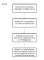
- a method for carrying out a safety-relevant action by means of a medical device comprising an inventive operating unit, especially for positioning at least one component of a medical device, wherein only in the event of the at least one first input field being touched and at the same time the at least one second input field located in the direction of touch behind the at least one first input field being actuated, the at least one device is activated accordingly and a safety-relevant action is executed.
- a control signal is transferred to a positioning device and as a result at least one component is positioned by means of the positioning device in accordance with the control signal.
- a duration of the actuation of the at least one operating unit is detected and only if a minimum duration is exceeded are the first and/or the second signal accepted by the processing unit.
- the duration of the actuation in this case can for example be determined by the processing unit and compared with a predetermined minimum duration, which as a rule corresponds to the usual duration of a desired actuation of the operating unit.
- the operating safety is greatly enhanced by the detection and evaluation of the duration of the actuation, since a short, inadvertent touching of the operating unit does not immediately lead to an actuation of the operating unit.
- the signal for activating the device which provides the operator with haptic feedback of a successful operation of the operating unit especially contains information about the type of haptic feedback to be output, for example in respect of a required vibration strength and/or the required vibration pattern.
- FIGS. 1 to 10 are intended to illustrate possible exemplary embodiments of operating units and their use. The figures show:
- FIG. 1 a first operating unit viewed from the side
- FIG. 2 the first operating unit in accordance with FIG. 1 viewed from above;
- FIG. 3 a second operating unit viewed from the side
- FIG. 4 the second operating unit in accordance with FIG. 3 viewed from above;
- FIG. 5 a third operating unit viewed from the side
- FIG. 6 a fourth operating unit viewed from the side
- FIG. 7 a fifth operating unit viewed from the side
- FIG. 8 the fifth operating unit in accordance with FIG. 7 viewed from above;
- FIG. 9 a schematic diagram of an electric circuit of an operating unit in accordance with FIG. 2 in a device.
- FIG. 10 a flowchart of an exemplary embodiment.
- FIG. 1 shows a schematic of a first operating unit 1 viewed from the side.
- FIG. 2 shows a schematic of the first operating unit 1 in accordance with FIG. 1 viewed from above.
- the operating unit 1 comprises a display 4 in the form of a liquid-crystal display, also known as an LCD, a transparent, touch-sensitive first input field 2 and a transparent, touch-sensitive second input field 3 .
- a display 4 in the form of a liquid-crystal display, also known as an LCD, a transparent, touch-sensitive first input field 2 and a transparent, touch-sensitive second input field 3 .
- the display 4 and the first and second input field 2 , 3 are the same size and disposed to cover the same area as each other.
- the display 4 and the two input fields 2 , 3 can however alternatively cover different areas and thus be disposed only partly overlapping.
- a device 6 Located on the rear side of the display 4 facing away from the operator of the operating unit 1 is a device 6 , which, after the operating unit 1 has been successfully operated by an operator, provides an operator with haptically perceivable feedback that the operation was successful.
- the device 6 typically involves a vibration motor which is in a position, if necessary in collaboration with a carrier unit, such as a baseplate or a housing, into which the operating unit 1 is built, to impart a haptically perceivable vibration to the operating unit 1 .
- the type and/or duration of the vibration in this case is characteristic of the type of action performed and/or a state of the device operated with the operating unit 1 .
- the electrical contact between the display 4 and the touch-sensitive input fields 2 , 3 is not shown in detail here for reasons of clarity and is sufficiently well known to the person skilled in the art.
- the information shown on the display 4 is usually fed in via a processing unit.
- the touch-sensitive first input field 2 can involve any known type of input field, for example a resistive, capacitive, sound-wave or optically-controlled input field.
- the first input field 2 is preferably a capacitive input field.
- the touch-sensitive second input field 3 can in principle likewise involve any known type of input field, for example a resistive, capacitive, sound-wave or optically-controlled input field.
- the second input field 3 is preferably of a different type from the first input field 2 , in order where possible to avoid any mutual influence between them.
- the second input field 2 is preferably a resistive input field.
- FIG. 3 shows a schematic of a second operating unit 1 ′ viewed from the side.
- FIG. 4 shows the second operating unit 1 ′ in accordance with FIG. 3 viewed from above.
- the operating unit 1 ′ again comprises a display 4 , a transparent, touch-sensitive first input field 2 and a transparent, touch-sensitive second input field 3 .
- the display 4 and the first and second input field 2 , 3 are the same size and disposed to cover the same area as each other.
- the display 4 and the two input fields 2 , 3 can however alternatively cover different areas and thus merely be disposed partly overlapping.
- the operating unit 1 ′ further comprises in accordance with FIG. 3 a carrier unit 5 or a base plate, which is shown here in cross-section and serves as a mechanical carrier for the display 4 , the first input field 2 and the second input field 3 .
- the devices 6 a , 6 b involve vibration motors for example, which are in a position to impart haptically perceivable vibration to the operating unit 1 .
- the embodiment of the carrier unit 5 is able to be varied in such cases within wide limits and it does not have to be a component of the operating unit 1 ′.
- FIG. 5 shows a schematic of a third operating unit 1 ′′ viewed from the side.
- the third operating unit 1 ′′ is constructed in a similar manner to the unit shown in FIG. 3 , with the same reference characters identifying the same elements.
- Disposed on the side of the third operating unit 1 ′′ facing towards an operator is a transparent protective film 7 for protection against mechanical and/or corrosive stresses, which can be a component of the third operating unit 1 ′′, but does not have to be.
- the image information displayed by the display 4 can be read out visually by the operator through transparent input fields 2 , 3 and the protective film 7 .
- the protective film 7 may not adversely affect the operability of the input fields 2 , 3 when touched in such cases.
- FIG. 6 shows a schematic of a fourth operating unit 1 ′ viewed from the side.
- the fourth operating unit 1 ′′′′ is similar in its construction to the unit shown in FIG. 3 , with the same reference characters identifying the same elements.
- the fourth operating unit 1 ′ comprises a carrier 5 , which is shown in cross-section and serves as a carrier for the display 4 , the first input field 2 and the second input field 3 .
- the devices 6 a , 6 b typically involve vibration motors, which are in a position to impart haptically perceivable vibration to the fourth operating unit 1 ′′′ inclusive or exclusive of the carrier unit 5 .
- the embodiment of the carrier unit 5 is able to be varied in such cases within wide limits and it does not have to be a component of the operating unit 1 ′′′.
- FIG. 7 shows a schematic of a fifth operating unit 10 viewed from the side.
- the fifth operating unit 10 is similar in its construction to the third operating unit 1 ′′ shown in FIG. 5 , with the same reference characters identifying the same elements.
- the fifth operating unit 10 here has a first input field 2 and a second input field 3 which are disposed to cover the same area as each other, but only partly cover the display 4 .
- FIG. 8 shows the fifth operating unit 10 in accordance with FIG. 7 viewed from above, wherein the transparent protective film 7 has been broken through in one area to shown the elements below it.
- FIG. 9 shows a schematic of an electric circuit of the first operating unit 1 in accordance with FIGS. 1 and 2 , which is built into a medical device 100 or another sort of device.
- the first switching signal S 1 which is generated when the first input field 2 is touched or actuated, is transferred to a processing unit 8 .
- the processing unit 8 here is a component of the medical device 100 , but does not always have to be.
- the second switching signal S 2 which is generated on actuation of the second input field 3 , is likewise transferred to the processing unit 8 .
- the processing unit 8 is configured to perform a synchronization as to whether both switching signals S 1 and S 2 are present at the same time.
- the processing unit 8 can also be configured, to determine the duration of the actuation of the first input field 2 and the second input field 2 , 3 and only when the duration exceeds a defined minimum duration, to classify them as plausible and accept them. Only when both switching signals S 1 and S 2 are present at the same time, especially for more than a minimum duration and/or not longer than a maximum duration, at least one control command or control signal B is output by the processing unit 8 . In this case at least one first control command B 1 is transferred to the device 6 , so that said device is activated and generates haptic feedback to the operator that the operator action was successful. Furthermore at least one second control command B 2 is output to carry out a safety-relevant action, for example to activate a positioning apparatus 9 of the medical device 100 , in order for example to change the position of a C-arm of the medical device 100 .
- the redundant detection of the switching signals S 1 and S 2 is of importance especially for devices in which incorrect operation or a defect of the operating unit can give rise to serious consequences.
- an operating element can include a plurality of first and second input fields each comprising one or more touch-sensitive areas, include input fields in more than two different embodiments, etc., without departing from the inventive idea.
Landscapes
- Engineering & Computer Science (AREA)
- General Engineering & Computer Science (AREA)
- Theoretical Computer Science (AREA)
- Human Computer Interaction (AREA)
- Physics & Mathematics (AREA)
- General Physics & Mathematics (AREA)
- User Interface Of Digital Computer (AREA)
- Position Input By Displaying (AREA)
Applications Claiming Priority (4)
| Application Number | Priority Date | Filing Date | Title |
|---|---|---|---|
| DE102009036941.4 | 2009-08-11 | ||
| DE102009036941.4A DE102009036941B4 (de) | 2009-08-11 | 2009-08-11 | Medizinisches Gerät und Verfahren |
| DE102009036941 | 2009-08-11 | ||
| PCT/EP2010/061573 WO2011018442A1 (de) | 2009-08-11 | 2010-08-10 | Bedieneinheit, medizinisches gerät und verfahren zum betrieb dieses geräts |
Publications (2)
| Publication Number | Publication Date |
|---|---|
| US20120188187A1 US20120188187A1 (en) | 2012-07-26 |
| US8860677B2 true US8860677B2 (en) | 2014-10-14 |
Family
ID=42740321
Family Applications (1)
| Application Number | Title | Priority Date | Filing Date |
|---|---|---|---|
| US13/389,877 Active 2031-06-25 US8860677B2 (en) | 2009-08-11 | 2010-08-10 | Operating unit, medical device and method for operating said unit |
Country Status (4)
| Country | Link |
|---|---|
| US (1) | US8860677B2 (de) |
| CN (1) | CN102473057B (de) |
| DE (1) | DE102009036941B4 (de) |
| WO (1) | WO2011018442A1 (de) |
Cited By (1)
| Publication number | Priority date | Publication date | Assignee | Title |
|---|---|---|---|---|
| US20200129134A1 (en) * | 2018-10-24 | 2020-04-30 | Siemens Healthcare Gmbh | Medical imaging device and method for operating a medical imaging device |
Families Citing this family (14)
| Publication number | Priority date | Publication date | Assignee | Title |
|---|---|---|---|---|
| DE102010064056A1 (de) | 2010-12-23 | 2012-06-28 | Siemens Aktiengesellschaft | Bedieneinheit, sowie Gerät und Verfahren |
| DE102011080752A1 (de) * | 2011-08-10 | 2013-02-14 | Siemens Aktiengesellschaft | Medizinisches Gerät |
| DE102011088196B4 (de) * | 2011-12-09 | 2015-11-19 | Continental Automotive Gmbh | Dateneingabevorrichtung eines Kraftfahrzeugs |
| DE102012201379A1 (de) * | 2012-01-31 | 2013-08-01 | Siemens Aktiengesellschaft | Berührungsempfindliche Bedieneinheit, medizinisches Gerät und Verfahren zur Bedienung |
| DE102012204018B4 (de) * | 2012-03-14 | 2022-09-01 | Siemens Healthcare Gmbh | Steuerungseinheit |
| CN103576903B (zh) * | 2012-07-24 | 2017-11-24 | 联想(北京)有限公司 | 一种信息处理方法及应用该方法的手写笔 |
| DE102012015524B4 (de) * | 2012-08-04 | 2014-04-03 | Audi Ag | Anzeigevorrichtung eines Kraftwagens |
| DE202012104316U1 (de) * | 2012-11-09 | 2012-11-28 | Optiplan Gesellschaft für optische Planungsgeräte mbH | Monitor |
| DE102013005662A1 (de) * | 2013-04-03 | 2014-10-09 | Heidelberger Druckmaschinen Ag | Touchscreen mit Sicherheitsfunktion |
| CN104252243B (zh) * | 2013-06-27 | 2017-08-15 | 南京迈瑞生物医疗电子有限公司 | 一种手势操控医疗设备及其手势操控方法 |
| DE102015209251A1 (de) * | 2015-05-20 | 2016-11-24 | Siemens Healthcare Gmbh | Medizinisches Gerät mit einer Bedieneinrichtung und Verfahren zum Betrieb einer Bedieneinrichtung |
| DE102016108634A1 (de) * | 2016-05-10 | 2017-11-16 | Preh Gmbh | Eingabegerät mit Berühr- beziehungsweise Betätigungsverifizierung |
| DE102019003997A1 (de) * | 2019-06-07 | 2020-12-10 | Drägerwerk AG & Co. KGaA | Eingabesystem und Verfahren zur Steuerung eines elektromedizinischen Geräts |
| BE1027408A9 (nl) | 2019-07-03 | 2021-02-08 | Clicktouch | Verbeterd aanraakscherm voor het detecteren van de locatie van een aanraking |
Citations (17)
| Publication number | Priority date | Publication date | Assignee | Title |
|---|---|---|---|---|
| US6504530B1 (en) | 1999-09-07 | 2003-01-07 | Elo Touchsystems, Inc. | Touch confirming touchscreen utilizing plural touch sensors |
| DE10151236A1 (de) | 2001-10-17 | 2003-05-08 | Siemens Ag | Vorrichtung zur optimierten Patienten-Positionierung bei Strahlenuntersuchungen und/oder Strahlenbehandlungen |
| CN1496549A (zh) | 2001-03-09 | 2004-05-12 | ��÷ɭ��˾ | 用于笔记本电脑和其它便携设备的触觉接口 |
| US20070080951A1 (en) * | 2002-08-29 | 2007-04-12 | Sony Corporation | Input device and electronic device using the input device |
| US20080004633A1 (en) * | 2006-05-19 | 2008-01-03 | Mako Surgical Corp. | System and method for verifying calibration of a surgical device |
| US20080084384A1 (en) | 2006-10-05 | 2008-04-10 | Immersion Corporation | Multiple Mode Haptic Feedback System |
| US20080259046A1 (en) * | 2007-04-05 | 2008-10-23 | Joseph Carsanaro | Pressure sensitive touch pad with virtual programmable buttons for launching utility applications |
| EP2009542A1 (de) | 2007-06-29 | 2008-12-31 | Barco N.V. | Zweifach-Touchscreen |
| US7479947B2 (en) * | 2001-11-20 | 2009-01-20 | Nokia Corporation | Form factor for portable device |
| EP2073107A1 (de) | 2007-12-10 | 2009-06-24 | Research In Motion Limited | Elektronische Vorrichtung und Touchscreen mit diskreten berührungsempfindlichen Bereichen |
| US20090176534A1 (en) | 2008-01-08 | 2009-07-09 | Lee Eun Hwa | Mobile terminal having flat panel sound output unit and vibration generation method for the same |
| US20090234302A1 (en) * | 2008-03-13 | 2009-09-17 | Medtronic,Inc. | Medical device and medical instrument alignment |
| US20100156818A1 (en) * | 2008-12-23 | 2010-06-24 | Apple Inc. | Multi touch with multi haptics |
| US20120103776A1 (en) * | 2010-10-29 | 2012-05-03 | Research In Motion Limited | Method and apparatus for controlling a multi-mode keyboard |
| US8385885B2 (en) * | 2008-10-17 | 2013-02-26 | Sony Ericsson Mobile Communications Ab | Method of unlocking a mobile electronic device |
| US20130150708A1 (en) * | 2011-12-07 | 2013-06-13 | Mako Surgical Corporation | Selectable Orientation Bent Tip Calibration-Free Probe |
| US8483802B2 (en) * | 2010-03-25 | 2013-07-09 | Medtronic, Inc. | Method and apparatus for guiding an external needle to an implantable device |
Family Cites Families (1)
| Publication number | Priority date | Publication date | Assignee | Title |
|---|---|---|---|---|
| DE10046099A1 (de) * | 2000-09-18 | 2002-04-04 | Siemens Ag | Berührungssensitive Anzeige mit taktiler Rückkopplung |
-
2009
- 2009-08-11 DE DE102009036941.4A patent/DE102009036941B4/de active Active
-
2010
- 2010-08-10 CN CN201080035510.2A patent/CN102473057B/zh active Active
- 2010-08-10 WO PCT/EP2010/061573 patent/WO2011018442A1/de active Application Filing
- 2010-08-10 US US13/389,877 patent/US8860677B2/en active Active
Patent Citations (18)
| Publication number | Priority date | Publication date | Assignee | Title |
|---|---|---|---|---|
| US6504530B1 (en) | 1999-09-07 | 2003-01-07 | Elo Touchsystems, Inc. | Touch confirming touchscreen utilizing plural touch sensors |
| CN1496549A (zh) | 2001-03-09 | 2004-05-12 | ��÷ɭ��˾ | 用于笔记本电脑和其它便携设备的触觉接口 |
| DE10151236A1 (de) | 2001-10-17 | 2003-05-08 | Siemens Ag | Vorrichtung zur optimierten Patienten-Positionierung bei Strahlenuntersuchungen und/oder Strahlenbehandlungen |
| US7479947B2 (en) * | 2001-11-20 | 2009-01-20 | Nokia Corporation | Form factor for portable device |
| US20070080951A1 (en) * | 2002-08-29 | 2007-04-12 | Sony Corporation | Input device and electronic device using the input device |
| US20080004633A1 (en) * | 2006-05-19 | 2008-01-03 | Mako Surgical Corp. | System and method for verifying calibration of a surgical device |
| US20080084384A1 (en) | 2006-10-05 | 2008-04-10 | Immersion Corporation | Multiple Mode Haptic Feedback System |
| US20080259046A1 (en) * | 2007-04-05 | 2008-10-23 | Joseph Carsanaro | Pressure sensitive touch pad with virtual programmable buttons for launching utility applications |
| US20090002329A1 (en) | 2007-06-29 | 2009-01-01 | Hans Van Genechten | Dual touchscreen |
| EP2009542A1 (de) | 2007-06-29 | 2008-12-31 | Barco N.V. | Zweifach-Touchscreen |
| EP2073107A1 (de) | 2007-12-10 | 2009-06-24 | Research In Motion Limited | Elektronische Vorrichtung und Touchscreen mit diskreten berührungsempfindlichen Bereichen |
| US20090176534A1 (en) | 2008-01-08 | 2009-07-09 | Lee Eun Hwa | Mobile terminal having flat panel sound output unit and vibration generation method for the same |
| US20090234302A1 (en) * | 2008-03-13 | 2009-09-17 | Medtronic,Inc. | Medical device and medical instrument alignment |
| US8385885B2 (en) * | 2008-10-17 | 2013-02-26 | Sony Ericsson Mobile Communications Ab | Method of unlocking a mobile electronic device |
| US20100156818A1 (en) * | 2008-12-23 | 2010-06-24 | Apple Inc. | Multi touch with multi haptics |
| US8483802B2 (en) * | 2010-03-25 | 2013-07-09 | Medtronic, Inc. | Method and apparatus for guiding an external needle to an implantable device |
| US20120103776A1 (en) * | 2010-10-29 | 2012-05-03 | Research In Motion Limited | Method and apparatus for controlling a multi-mode keyboard |
| US20130150708A1 (en) * | 2011-12-07 | 2013-06-13 | Mako Surgical Corporation | Selectable Orientation Bent Tip Calibration-Free Probe |
Cited By (2)
| Publication number | Priority date | Publication date | Assignee | Title |
|---|---|---|---|---|
| US20200129134A1 (en) * | 2018-10-24 | 2020-04-30 | Siemens Healthcare Gmbh | Medical imaging device and method for operating a medical imaging device |
| US11627927B2 (en) * | 2018-10-24 | 2023-04-18 | Siemens Healthcare Gmbh | Medical imaging device having a movable patient couch and a touch-sensitive and force-sensitive interface for controlling the movable patient couch, and method for operating a medical imaging device |
Also Published As
| Publication number | Publication date |
|---|---|
| DE102009036941A1 (de) | 2011-02-17 |
| CN102473057B (zh) | 2015-08-12 |
| CN102473057A (zh) | 2012-05-23 |
| DE102009036941B4 (de) | 2014-03-20 |
| US20120188187A1 (en) | 2012-07-26 |
| WO2011018442A1 (de) | 2011-02-17 |
Similar Documents
| Publication | Publication Date | Title |
|---|---|---|
| US8860677B2 (en) | Operating unit, medical device and method for operating said unit | |
| WO2011018439A1 (de) | Bedieneinheit, gerät und verfahren | |
| JP5563417B2 (ja) | タッチパネル付き表示装置 | |
| CN108433823B (zh) | 用于操作医疗仪器的操作设备和操作方法 | |
| US7783009B2 (en) | Redundant switch mechanism for safety-critical applications in medical systems | |
| US7302040B2 (en) | Device for medical provision | |
| JPH11313801A (ja) | 医学技術的システム | |
| JP2012084025A (ja) | タッチパネル付き表示装置 | |
| JP6176832B2 (ja) | 支持器及びx線診断装置 | |
| US11861164B2 (en) | Interface for a medical device with an adaptive actuation sensor | |
| US20140258917A1 (en) | Method to operate a device in a sterile environment | |
| CN103975298A (zh) | 具有能够手动操作的触敏表面的操纵设备 | |
| JP5732172B2 (ja) | タッチパネルシステム及び電子情報機器 | |
| WO2016194107A1 (ja) | 表示確認装置、液晶ディスプレイ装置、メータディスプレイ、及び表示確認方法 | |
| DE102010064056A1 (de) | Bedieneinheit, sowie Gerät und Verfahren | |
| DE102012207114A1 (de) | Berührungsempfindliche Bedieneinheit, medizinisches Gerät und Verfahren zur Bedienung | |
| US9691966B2 (en) | Surface-mounted collision sensor, and method for collision detection | |
| WO2005051192A2 (de) | Berührungsempfindliche eingabevorrichtung und fehlererkennungsvorrichtung für eine berührungsempfindliche eingabevorrichtung, insbesondere für medizintechnische geräte | |
| US20200192546A1 (en) | Display device, machine tool and abnormality determination method | |
| CN106021900B (zh) | 用于运行医疗设备的方法以及医疗设备 | |
| US20240118768A1 (en) | Diagnosis device and diagnosis method | |
| JP2012239534A (ja) | X線透視撮影台 | |
| JP2022138016A (ja) | タッチパネル、タッチパネルシステム、およびタッチパネルシステムの制御方法 | |
| JP2013123629A (ja) | X線撮影装置 | |
| CN111133404B (zh) | 工业操作面板 |
Legal Events
| Date | Code | Title | Description |
|---|---|---|---|
| AS | Assignment |
Owner name: SIEMENS AKTIENGESELLSCHAFT, GERMANY Free format text: ASSIGNMENT OF ASSIGNORS INTEREST;ASSIGNORS:DOERRE, HELMUT;HARTLEIB, DOMINIK;KARL, HARALD;AND OTHERS;SIGNING DATES FROM 20120223 TO 20120228;REEL/FRAME:028011/0247 |
|
| STCF | Information on status: patent grant |
Free format text: PATENTED CASE |
|
| AS | Assignment |
Owner name: SIEMENS HEALTHCARE GMBH, GERMANY Free format text: ASSIGNMENT OF ASSIGNORS INTEREST;ASSIGNOR:SIEMENS AKTIENGESELLSCHAFT;REEL/FRAME:039271/0561 Effective date: 20160610 |
|
| MAFP | Maintenance fee payment |
Free format text: PAYMENT OF MAINTENANCE FEE, 4TH YEAR, LARGE ENTITY (ORIGINAL EVENT CODE: M1551) Year of fee payment: 4 |
|
| MAFP | Maintenance fee payment |
Free format text: PAYMENT OF MAINTENANCE FEE, 8TH YEAR, LARGE ENTITY (ORIGINAL EVENT CODE: M1552); ENTITY STATUS OF PATENT OWNER: LARGE ENTITY Year of fee payment: 8 |
|
| AS | Assignment |
Owner name: SIEMENS HEALTHINEERS AG, GERMANY Free format text: ASSIGNMENT OF ASSIGNORS INTEREST;ASSIGNOR:SIEMENS HEALTHCARE GMBH;REEL/FRAME:066088/0256 Effective date: 20231219 |