US8826548B2 - Hand-held jigsaw - Google Patents
Hand-held jigsaw Download PDFInfo
- Publication number
- US8826548B2 US8826548B2 US12/281,442 US28144207A US8826548B2 US 8826548 B2 US8826548 B2 US 8826548B2 US 28144207 A US28144207 A US 28144207A US 8826548 B2 US8826548 B2 US 8826548B2
- Authority
- US
- United States
- Prior art keywords
- saw blade
- hand
- held jigsaw
- jigsaw
- recited
- Prior art date
- Legal status (The legal status is an assumption and is not a legal conclusion. Google has not performed a legal analysis and makes no representation as to the accuracy of the status listed.)
- Expired - Fee Related, expires
Links
Images


Classifications
-
- B—PERFORMING OPERATIONS; TRANSPORTING
- B23—MACHINE TOOLS; METAL-WORKING NOT OTHERWISE PROVIDED FOR
- B23D—PLANING; SLOTTING; SHEARING; BROACHING; SAWING; FILING; SCRAPING; LIKE OPERATIONS FOR WORKING METAL BY REMOVING MATERIAL, NOT OTHERWISE PROVIDED FOR
- B23D49/00—Machines or devices for sawing with straight reciprocating saw blades, e.g. hacksaws
- B23D49/10—Hand-held or hand-operated sawing devices with straight saw blades
- B23D49/16—Hand-held or hand-operated sawing devices with straight saw blades actuated by electric or magnetic power or prime movers
- B23D49/162—Pad sawing devices
- B23D49/167—Pad sawing devices with means to adjust the guide plate or with means to adjust the plane in which the saw blade moves
-
- B—PERFORMING OPERATIONS; TRANSPORTING
- B23—MACHINE TOOLS; METAL-WORKING NOT OTHERWISE PROVIDED FOR
- B23D—PLANING; SLOTTING; SHEARING; BROACHING; SAWING; FILING; SCRAPING; LIKE OPERATIONS FOR WORKING METAL BY REMOVING MATERIAL, NOT OTHERWISE PROVIDED FOR
- B23D51/00—Sawing machines or sawing devices working with straight blades, characterised only by constructional features of particular parts; Carrying or attaching means for tools, covered by this subclass, which are connected to a carrier at both ends
- B23D51/02—Sawing machines or sawing devices working with straight blades, characterised only by constructional features of particular parts; Carrying or attaching means for tools, covered by this subclass, which are connected to a carrier at both ends of beds; of guiding arrangements for work-tables or saw carriers; of frames
-
- B—PERFORMING OPERATIONS; TRANSPORTING
- B23—MACHINE TOOLS; METAL-WORKING NOT OTHERWISE PROVIDED FOR
- B23D—PLANING; SLOTTING; SHEARING; BROACHING; SAWING; FILING; SCRAPING; LIKE OPERATIONS FOR WORKING METAL BY REMOVING MATERIAL, NOT OTHERWISE PROVIDED FOR
- B23D59/00—Accessories specially designed for sawing machines or sawing devices
- B23D59/001—Measuring or control devices, e.g. for automatic control of work feed pressure on band saw blade
- B23D59/002—Measuring or control devices, e.g. for automatic control of work feed pressure on band saw blade for the position of the saw blade
-
- Y—GENERAL TAGGING OF NEW TECHNOLOGICAL DEVELOPMENTS; GENERAL TAGGING OF CROSS-SECTIONAL TECHNOLOGIES SPANNING OVER SEVERAL SECTIONS OF THE IPC; TECHNICAL SUBJECTS COVERED BY FORMER USPC CROSS-REFERENCE ART COLLECTIONS [XRACs] AND DIGESTS
- Y10—TECHNICAL SUBJECTS COVERED BY FORMER USPC
- Y10T—TECHNICAL SUBJECTS COVERED BY FORMER US CLASSIFICATION
- Y10T83/00—Cutting
- Y10T83/525—Operation controlled by detector means responsive to work
- Y10T83/531—With plural work-sensing means
-
- Y—GENERAL TAGGING OF NEW TECHNOLOGICAL DEVELOPMENTS; GENERAL TAGGING OF CROSS-SECTIONAL TECHNOLOGIES SPANNING OVER SEVERAL SECTIONS OF THE IPC; TECHNICAL SUBJECTS COVERED BY FORMER USPC CROSS-REFERENCE ART COLLECTIONS [XRACs] AND DIGESTS
- Y10—TECHNICAL SUBJECTS COVERED BY FORMER USPC
- Y10T—TECHNICAL SUBJECTS COVERED BY FORMER US CLASSIFICATION
- Y10T83/00—Cutting
- Y10T83/828—With illuminating or viewing means for work
Definitions
- German Patent Applications whose subject matter is incorporated here by reference, provides the basis for a claim of priority of invention under 35 U.S.C. 119(a)-(d).
- the present invention relates to a hand-held jigsaw.
- the publications US 2005/0060896 A1 and US 2005/0257985 A1 have disclosed jigsaws that are referred to as “scrolling jigsaws” and in which the saw blade is situated so that in addition to executing the stroke motion, it can be rotated manually independently of the sawing motion. This additional function facilitates the sawing of sinuous cuts.
- the invention is based on a hand-held jigsaw, in particular a scrolling jigsaw.
- control means are provided that make it possible to automate a tracking of a saw blade and/or of the hand-held jigsaw along layout lines.
- a “control means” is understood in particular to be a means that permits a required orientation of the saw blade and/or the hand-held jigsaw and/or a component of the hand-held jigsaw such as a glide element to be detected and/or adapted to the orientation.
- This control means can be a detection unit such as a sensor system embodied in the form of a sensor and/or an actuator system embodied in the form of an actuating unit such as a servo motor and/or a step motor and/or a piezoelectric actuator.
- tracking here defines an orientation along a predetermined path that is preferably indicated by means of a marking.
- This marking can be a layout line such as a previously drawn pencil line and/or another marking deemed suitable by a person skilled in the art, such as an indentation and/or some other form of profiling.
- the hand-held jigsaw is equipped with a special sensor system for detecting a previously drawn line or layout line and a corresponding actuator system for automatically adjusting the saw blade angle from an angle range of a pivot angle.
- the rotation axis here is defined by a normal that extends through a center point of a plane defined by a thickness and a width of the saw blade.
- the rotation axis of the saw blade can also be situated other than at its center point.
- the pivot angle represents the angle by which the saw blade can be maximally adjusted around its longitudinal axis in relation to a longitudinal axis of the glide element and/or another guidance component deemed suitable by a person skilled in the art, e.g. a chassis.
- This pivot angle is preferably an angle of between 0° and 90°.
- the saw blade angle of the saw blade is the angle that is actually set between the lateral span of the saw blade and the longitudinal axis of the glide element or a guidance component.
- a hand-held jigsaw has a pivotable saw blade that can be driven by the control means, then a tracking of the previously drawn line by the saw blade can occur in an advantageous, structurally simple fashion.
- the term “pivotable” here is particularly understood to mean a turning and/or rotation of the saw blade in an axis that preferably extends parallel to a longitudinal span of the saw blade. In this connection, the turning can be achieved by clamping the saw blade into a tool socket and/or through some other exertion of force on the saw blade.
- the invention is also based on a hand-held jigsaw, in particular a scrolling jigsaw.
- a sensor for detecting a layout line provided on a workpiece.
- the term “sensor” is understood in particular here to mean a camera unit and/or a contrast sensor unit and/or an eddy current sensor unit. This makes it possible to achieve a detection of a desired cutting direction in a particularly advantageous, inexpensive, structurally simple fashion.
- the invention is also based on a hand-held jigsaw, in particular a scrolling jigsaw.
- optical mouse sensors are provided for determining a speed and/or a movement direction.
- optical mouse sensor is understood here to mean a sensor that uses optical means such as a light-emitting diode or laser diode to illuminate a supporting surface, evaluates a light reflected against the supporting surface, calculates a speed based on the change of a physical surface of the supporting surface, and from this, calculates the movement data in the x and/or y direction.
- the movement direction and/or the advancing speed can also be determined by means of a running wheel with an angular displacement transducer, e.g.
- a rolling element with corresponding photoelectric beam detectors that detect a movement in at least two directions such as an x direction and a y direction.
- means that are used to compare individual camera images can also be provided to determine the advancing speed.
- optical mouse sensors makes it possible for a rugged sensor system for determining the speed and/or a movement direction to be produced in a particularly simple and inexpensive fashion.
- the invention is also based on a hand-held jigsaw, in particular a scrolling jigsaw.
- an actuator with a regulator is provided.
- An “actuator with a regulator” is understood here to be a unit that processes data from a detection unit, particularly in a control loop, and/or reacts to and/or transmits generated control signals.
- This unit is preferably embodied in the form of a servo motor and/or a step motor and/or a piezoelectric actuator and/or a DC motor with a regulator unit. It is thus possible for a control loop for precisely tracking a predetermined cutting line to be implemented in a structurally simple and inexpensive fashion.
- the invention is also based on a hand-held jigsaw, in particular a scrolling jigsaw.
- a display element is produced, which is provided to display a recommended advancing direction.
- a “display element” is understood here to mean an element that optically, acoustically, and/or tactilely informs the operator of the path detected by a sensor or of a course of the layout line.
- the display element here can be composed of LEDs and/or a display and/or another data unit deemed suitable by a person skilled in the art. This makes it advantageously possible for an operator to receive information relating to a desired movement direction, regardless of whether the operator is able to see the saw blade. This makes it possible for an operator to stay within an optimal working region that represents an angular range of the possible saw blade angle.
- FIG. 1 shows a hand-held jigsaw according to the invention
- FIG. 2 shows a glide shoe of the hand-held jigsaw according to the invention, embodied in the form of a base plate and equipped with optical sensors,
- FIG. 3 shows an alternative glide shoe of the hand-held jigsaw according to the invention, embodied in the form of a base plate,
- FIG. 4 shows an alternative glide shoe of the hand-held jigsaw according to the invention, embodied in the form of a base plate and equipped with alternative sensors, and
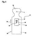
- FIG. 5 shows a top view of the hand-held jigsaw.
- FIG. 1 is a perspective side view of a hand-held jigsaw 9 according to the invention, embodied in the form of a scrolling jigsaw.
- the hand-held jigsaw 9 includes a machine housing 44 , a main handle 46 integrated into the machine housing 44 , and a tool socket 48 containing a tool in the form of a rotatably supported saw blade 12 .
- a glide element or glide shoe 8 in the form of a base plate is situated on a side 50 oriented toward the work piece 18 to be machined. This glide shoe 8 permits the hand-held jigsaw 9 to advantageously glide on the work piece 18 .
- a guide knob is provided, which is used for an at least manual guidance of the hand-held jigsaw 9 .
- the machine housing 44 also contains a motor that is not shown in detail.
- an actuation switch 56 is provided, which can be used to switch the hand-held jigsaw 9 on and off.
- an adjusting switch 60 is also provided, which can be used to adjust the glide shoe 8 in relation to a main span 62 of the saw blade 12 .
- the hand-held jigsaw 9 includes control means 10 , 100 that enable an automation of a tracking of the saw blade 12 along the layout line 14 .
- the control means 10 is situated in a part 66 of the machine housing 44 spaced apart from the main handle 46 in the axial direction 64 .
- the control means 10 includes a sensor 16 for detecting or optically scanning a marking or layout line 14 in the form of a normal pencil line 3 provided on the work piece 18 .
- the sensor 16 is composed of a camera unit 7 that preferably includes a low-cost camera and that is associated with a processor unit 28 .
- the sensor 16 could also be a contrast sensor unit 20 and/or eddy current sensor unit 22 associated with a respective processor unit 28 .
- the eddy current sensor 22 to be situated in the glide shoe 8 .
- a monitoring region 68 of the sensor 16 and of the camera unit 7 extends toward the work piece 18 in the same direction as the main span 62 of the saw blade 12 and covers a 360° angular range around the saw blade 12 .
- the monitoring region 68 of the camera unit 7 represents the region in which the saw blade 12 functions in an operating mode, preferably a sawing procedure of a work piece 18 .
- the glide shoe 8 Around the saw blade 12 , the glide shoe 8 has a semicircular opening 70 in which the saw blade 12 is centrally situated. In the direction of an advancing direction 38 and in the direction of the monitoring region 68 , the opening 70 has a rectangular viewing window 102 .
- the glide shoe 8 also has a reference mark 74 that represents the intersecting point of an edge 76 of the glide shoe 8 with a longitudinal axis 78 of the glide shoe 8 (see FIG. 2 ).
- FIG. 3 shows an alternative embodiment of the glide shoe 8 .
- the central opening 70 widens out in a V-shape to form a viewing region 72 .
- FIG. 4 shows another alternative embodiment of the glide shoe 8 with a circular opening 70 .
- the glide shoe 8 is closed in the monitoring region 68 and is embodied as transparent, e.g. is composed of Plexiglas, in order to make it possible to monitor the layout line 14 on the work piece 18 (see FIG. 4 ).
- the machine housing 44 of the handheld jigsaw 9 contains a compact actuator system 2 that is able to adjust the saw blade 12 around a rotation axis 1 in an automated fashion.
- the control means 100 is provided for this purpose.
- the control means 100 represents an actuator unit 30 , embodied in the form of an actuator with a regulator 34 in the form of a step motor by means of which it is possible to adjust a saw blade angle 26 of a saw blade 12 .
- the control means 100 and the step motor can also be situated in a space-saving fashion as an alternative to the guide knob 54 .
- the saw blade angle 26 is an angle ⁇ from the angular range of a pivot angle 80 that is actually set between the width span 82 of the saw blade 12 and the longitudinal axis 78 of the glide shoe 8 .
- the pivot angle 80 represents the angle ⁇ max by which the saw blade 12 can be moved around its longitudinal axis, which extends parallel to the main span direction 62 of the saw blade 12 , in relation to a longitudinal axis 78 of the glide shoe 8 (see FIG. 2 ).
- control means 10 , 100 With the aid of the control means 10 , 100 , namely the sensor 16 and the actuator unit 30 , it is possible to implement a control loop in order to achieve the most exact possible tracking of the predetermined line or layout line 14 .
- the exceptional feature in this case lies on the one hand in the fact that an analog image processing is used to detect the layout line 14 and on the other hand, lies in the automation of the system. It is consequently possible to execute clean, precise cuts by hand and to actively prevent a deviation of the saw blade 12 .
- the sensor 16 in the form of a camera unit 7 detects individual points 4 of the previously drawn line or layout line 14 .
- the sensor 16 uses an analog image processing that uses a division of the monitoring region 68 into individual search lines 6 without digital image processing.
- the use of the camera unit 7 is particularly advantageous since it does not require calculation-intensive digital image processing.
- the collected sensor information and the data associated with the detected points 4 are then transmitted by the sensor 16 to the processor unit 28 , which processes the detected points 4 further and based on them, interpolates and adapts an actual path curve 24 (spline).
- the processor unit 28 can be a microcontroller or another processing unit deemed suitable by a person skilled in the art.
- the processing unit 28 calculates and generates control signals and transmits control signals to the actuator unit 30 for an adjustment of the saw blade angle 26 .
- the actuator unit 30 By means of an actuating element with a regulator 34 in the form of a step motor, the actuator unit 30 then correspondingly adapts the saw blade angle 26 , i.e. the angle ⁇ around the longitudinal axis parallel to the main span direction 62 of the saw blade 12 , as a function of the overlaid user guidance by means of the guide knob 54 of the hand-held jigsaw 9 .
- the use of the sensor 16 and the camera unit 7 also offers the possibility of measuring additional reference marks 74 by means of the glide shoe 8 .
- the sensor 16 can be used for detecting the set saw blade angle 26 and for determining the rotation angle of the saw blade 12 . This makes it possible to eliminate additional cost-intensive sensors that unnecessarily take up space.
- optical mouse sensors 5 are situated in the glide shoe 8 on a side 84 oriented toward the work piece 18 and determine the speed and a movement direction, preferably in the x and/or y direction (see FIG. 3 ).
- FIG. 4 shows another possibility for detecting the advancing speed.
- a simple running wheel with an angular displacement transducer 32 is provided, e.g. a rolling element 86 with corresponding photoelectric beam detectors 88 .
- other approaches are also conceivable, for example the comparison of individual camera images by means of the processor unit 28 .
- the system can also be implemented without a speed measurement.
- the system composed of the control means 10 , 100 i.e. of the sensor 16 and actuator unit 30 , is conceived only for the fine regulation that compensates for irregularities in the saw blade path and/or user guidance.
- This system is understood solely as an assisting system, i.e. if no layout line 14 can be detected (end of a line, multiple lines), the system gives a warning by means of an acoustic and/or optical unit 90 , stabilizes the current saw blade angle 26 , and leaves the control up to the operator, as in conventional jigsaws. No active intervention occurs. If so desired, the system, which can be associated with one or more means and which permits automation of a tracking of the saw blade 12 and/or the hand-held jigsaw 9 along layout lines 14 , can be switched off at any time, even preferably manually by the operator.
- the system advantageously includes the actuator system 2 , at least one or speed-detecting sensor such as the optical mouse sensor 5 , the control means 10 in the form of the sensor 16 and the camera unit 7 , the control means 100 in the form of the actuating unit 30 , and the actuator with a regulator 34 .
- a switch 92 is provided in the region of the main handle 46 on the machine housing 40 .
- a display element 36 e.g. in the form of LEDs 40 and/or a display 42 , is situated on a side 94 of the machine housing 44 or main handle 46 oriented toward the operator, in the operator's field of view.
- This display element 36 is provided to display a recommended advancing direction 38 , for example symbolized by means of an arrow symbol 96 composed of light-emitting diodes or LEDs 40 .
- the operator is thus shown the direction in which the saw movement must be corrected. Consequently, the display element 36 makes it possible for the operator to stay within an optimum working region that represents an angular range of the possible saw blade angle 26 .
- a blower 98 is provided, which is able to remove or suck away machining residue generated by the sawing process.
Landscapes
- Engineering & Computer Science (AREA)
- Mechanical Engineering (AREA)
- Sawing (AREA)
Applications Claiming Priority (4)
| Application Number | Priority Date | Filing Date | Title |
|---|---|---|---|
| DE102006052808.5 | 2006-11-09 | ||
| DE200610052808 DE102006052808A1 (de) | 2006-11-09 | 2006-11-09 | Handhubsägemaschine |
| DE102006052808 | 2006-11-09 | ||
| PCT/EP2007/059965 WO2008055738A1 (de) | 2006-11-09 | 2007-09-20 | Handhubsägemaschine |
Publications (2)
| Publication Number | Publication Date |
|---|---|
| US20090025233A1 US20090025233A1 (en) | 2009-01-29 |
| US8826548B2 true US8826548B2 (en) | 2014-09-09 |
Family
ID=38829606
Family Applications (2)
| Application Number | Title | Priority Date | Filing Date |
|---|---|---|---|
| US12/281,442 Expired - Fee Related US8826548B2 (en) | 2006-11-09 | 2007-09-20 | Hand-held jigsaw |
| US13/231,139 Abandoned US20120000080A1 (en) | 2006-11-09 | 2011-09-13 | Hand-held power jigsaw |
Family Applications After (1)
| Application Number | Title | Priority Date | Filing Date |
|---|---|---|---|
| US13/231,139 Abandoned US20120000080A1 (en) | 2006-11-09 | 2011-09-13 | Hand-held power jigsaw |
Country Status (6)
| Country | Link |
|---|---|
| US (2) | US8826548B2 (de) |
| EP (1) | EP2089178A1 (de) |
| CN (2) | CN102717152B (de) |
| DE (1) | DE102006052808A1 (de) |
| RU (1) | RU2465988C2 (de) |
| WO (1) | WO2008055738A1 (de) |
Cited By (13)
| Publication number | Priority date | Publication date | Assignee | Title |
|---|---|---|---|---|
| US20130062087A1 (en) * | 2009-12-18 | 2013-03-14 | Robert Bosch Gmbh | Machine Tool System, Especially a Jigsaw System |
| US20150113815A1 (en) * | 2013-10-25 | 2015-04-30 | Black & Decker Inc. | Compact Power Tool Handle |
| US20150277421A1 (en) * | 2011-05-19 | 2015-10-01 | Taktia Llc | Automatically guided tools |
| US20160311041A1 (en) * | 2015-04-22 | 2016-10-27 | Wesley Harold Hutchcraft | Blade fan |
| US9925684B2 (en) * | 2012-07-04 | 2018-03-27 | Robert Bosch Gmbh | Cut length indicating device |
| US10456883B2 (en) | 2015-05-13 | 2019-10-29 | Shaper Tools, Inc. | Systems, methods and apparatus for guided tools |
| US10556356B2 (en) | 2012-04-26 | 2020-02-11 | Sharper Tools, Inc. | Systems and methods for performing a task on a material, or locating the position of a device relative to the surface of the material |
| US10562116B2 (en) | 2016-02-03 | 2020-02-18 | Milwaukee Electric Tool Corporation | System and methods for configuring a reciprocating saw |
| USD887806S1 (en) | 2018-04-03 | 2020-06-23 | Milwaukee Electric Tool Corporation | Jigsaw |
| US10835972B2 (en) | 2018-03-16 | 2020-11-17 | Milwaukee Electric Tool Corporation | Blade clamp for power tool |
| US11014224B2 (en) | 2016-01-05 | 2021-05-25 | Milwaukee Electric Tool Corporation | Vibration reduction system and method for power tools |
| US11014176B2 (en) | 2018-04-03 | 2021-05-25 | Milwaukee Electric Tool Corporation | Jigsaw |
| US11537099B2 (en) | 2016-08-19 | 2022-12-27 | Sharper Tools, Inc. | Systems, methods and apparatus for sharing tool fabrication and design data |
Families Citing this family (37)
| Publication number | Priority date | Publication date | Assignee | Title |
|---|---|---|---|---|
| DE102008001757A1 (de) | 2008-05-14 | 2009-11-19 | Robert Bosch Gmbh | Werkzeugmaschine, insbesondere handgehaltene Werkzeugmaschine |
| DE102008001809A1 (de) * | 2008-05-15 | 2009-11-19 | Robert Bosch Gmbh | Arbeitsverfahren für eine Werkzeugmaschine, insbesondere eine handgehaltene Werkzeugmaschine |
| DE102008002066A1 (de) * | 2008-05-29 | 2009-12-03 | Robert Bosch Gmbh | Werkzeugmaschine, insbesondere handgeführte Werkzeugmaschine |
| DE102008040071A1 (de) | 2008-07-02 | 2010-01-07 | Robert Bosch Gmbh | Werkzeugmaschine, insbesondere handgehaltene Werkzeugmaschine |
| DE102008040064A1 (de) * | 2008-07-02 | 2010-01-07 | Robert Bosch Gmbh | Motorisch betriebene Arbeitsvorrichtung |
| DE102008041088A1 (de) * | 2008-08-07 | 2010-02-11 | Robert Bosch Gmbh | Verfahren zum Betreiben einer Werkzeugmaschine, und Werkzeugmaschine hierfür |
| DE102008055062A1 (de) * | 2008-12-22 | 2010-06-24 | Robert Bosch Gmbh | Eingriffs-Schutzsystem für Maschinen |
| DE102008055058A1 (de) * | 2008-12-22 | 2010-06-24 | Robert Bosch Gmbh | Werkzeugmaschine, insbesondere Handwerkzeugmaschine |
| DE102008055061A1 (de) * | 2008-12-22 | 2010-06-24 | Robert Bosch Gmbh | Führungssystem für Werkzeugmaschinen |
| DE102008055067A1 (de) | 2008-12-22 | 2010-07-01 | Robert Bosch Gmbh | Werkzeugmaschine, insbesondere handgehaltene Werkzeugmaschine |
| DE102008055059A1 (de) * | 2008-12-22 | 2010-06-24 | Robert Bosch Gmbh | Werkzeugmaschine, insbesondere Handwerkzeugmaschine |
| DE102008055057A1 (de) | 2008-12-22 | 2010-06-24 | Robert Bosch Gmbh | Werkzeugmaschine, insbesondere handgehaltene Werkzeugmaschine |
| DE102008055066A1 (de) | 2008-12-22 | 2010-07-01 | Robert Bosch Gmbh | Werkzeugmaschine, insbesondere handgehaltene Werkzeugmaschine |
| JP5444736B2 (ja) * | 2009-01-29 | 2014-03-19 | 日立工機株式会社 | エンジンカッタ、車輪付きエンジンカッタ及び切削方法 |
| DE102009027310A1 (de) | 2009-06-30 | 2011-01-05 | Robert Bosch Gmbh | Werkzeugmaschine, insbesondere Handwerkzeugmaschine |
| DE102009028556A1 (de) * | 2009-08-14 | 2011-02-17 | Robert Bosch Gmbh | Sägevorrichtung, insbesondere Stichsägevorrichtung |
| DE102009029104A1 (de) * | 2009-09-02 | 2011-03-03 | Robert Bosch Gmbh | Werkzeugvorrichtung |
| DE102009044916A1 (de) | 2009-09-23 | 2011-04-07 | Robert Bosch Gmbh | Werkzeugmaschine, insbesondere handgehaltene Werkzeugmaschine |
| DE102009045235A1 (de) * | 2009-10-01 | 2011-04-28 | Robert Bosch Gmbh | Werkzeugmaschine, insbesondere handgehaltene Werkzeugmaschine |
| DE102009054709A1 (de) * | 2009-12-16 | 2011-06-22 | Robert Bosch GmbH, 70469 | Werkzeugmaschine, insbesondere handgehaltene Werkzeugmaschine |
| DE102009054977A1 (de) | 2009-12-18 | 2011-06-22 | Robert Bosch GmbH, 70469 | Werkzeugmaschinensystem, insbesondere für handgehaltene Werkzeugmaschinen |
| US8763720B2 (en) * | 2010-05-18 | 2014-07-01 | Jason Lee Moore | Interactive tools |
| DE102010041726A1 (de) * | 2010-09-30 | 2012-04-05 | Robert Bosch Gmbh | Handwerkzeugmaschinenvorrichtung |
| DE102011086419A1 (de) | 2011-11-15 | 2013-05-16 | Robert Bosch Gmbh | Verfahren zur sensorischen Bilderfassung sowie Verwendung eines solchen Verfahrens in einem Elektrowerkzeug |
| DE102012213013A1 (de) | 2012-07-25 | 2014-01-30 | Robert Bosch Gmbh | Halbautonome Stichsäge |
| CN107680918B (zh) | 2012-09-19 | 2021-02-23 | 应用材料公司 | 接合基板的方法 |
| DE102013208132A1 (de) * | 2013-05-03 | 2014-11-06 | Robert Bosch Gmbh | Handwerkzeugmaschine |
| DE102013221092A1 (de) * | 2013-10-17 | 2015-04-23 | Robert Bosch Gmbh | Handgeführte Stichsäge |
| DE102014209011A1 (de) * | 2014-05-13 | 2015-11-19 | Robert Bosch Gmbh | Handgeführte semiautonome Stichsäge |
| US9643290B1 (en) * | 2014-06-25 | 2017-05-09 | Andrew Leighner | Line following power tool |
| JP6678314B2 (ja) * | 2015-03-12 | 2020-04-08 | パナソニックIpマネジメント株式会社 | 切断工具 |
| DE102016216782A1 (de) | 2016-09-06 | 2018-03-08 | Robert Bosch Gmbh | Messvorrichtung für eine Sägemaschine |
| US10136655B2 (en) * | 2016-10-19 | 2018-11-27 | William M Haack | Saw blade illuminating safety device |
| DE102017129813A1 (de) | 2017-09-29 | 2019-04-04 | Festool Gmbh | Mobile Werkzeugmaschine |
| DE102017129809A1 (de) * | 2017-09-29 | 2019-04-04 | Festool Gmbh | Mobile Werkzeugmaschine |
| DE102017126486B4 (de) * | 2017-11-02 | 2019-10-24 | Festool Gmbh | Hand-Werkzeugmaschine mit unter Beibehaltung ihrer Schwenkstellung verstellbarer Werkzeugaufnahme |
| DE102019108793A1 (de) * | 2018-06-12 | 2019-12-12 | Festool Gmbh | Hand-Werkzeugmaschine |
Citations (30)
| Publication number | Priority date | Publication date | Assignee | Title |
|---|---|---|---|---|
| US3456698A (en) | 1966-03-25 | 1969-07-22 | Ackermanu U Schmitt Kg | Motor-driven manually operable compass saw |
| US3504716A (en) * | 1966-12-28 | 1970-04-07 | Stanley Works | Power tool and guide therefor |
| US3610081A (en) * | 1970-02-09 | 1971-10-05 | Gerber Garment Technology Inc | Automatic sheet material cutter with cutting tool angle checking means |
| US4380944A (en) * | 1979-09-10 | 1983-04-26 | Gerber Garment Technology, Inc. | Method for cutting sheet material with variable gain closed loop |
| SU1083117A1 (ru) | 1982-10-04 | 1984-03-30 | Вильнюсский Ордена Трудового Красного Знамени И Ордена Дружбы Народов Государственный Университет Им.В.Капсукаса | Устройство дл измерени скорости и направлени движени |
| US4630109A (en) * | 1985-02-28 | 1986-12-16 | Standard Telephones & Cables Public Limited Company | Vehicle tracking system |
| SU1483255A1 (ru) | 1987-12-28 | 1989-05-30 | Предприятие П/Я А-1891 | Фотоэлектрический датчик перемещений |
| US5010652A (en) * | 1990-03-19 | 1991-04-30 | Miletich David J | Optically guided power sabre saw |
| DE3942901A1 (de) | 1989-12-23 | 1991-06-27 | Licentia Gmbh | Handgefuehrte elektrowerkzeugmaschine |
| EP0588057A2 (de) | 1992-09-16 | 1994-03-23 | Robert Bosch Gmbh | Verfahren zur Optimierung des Arbeitsvorgangs eines Elektrohandwerkzeugs |
| US5928137A (en) * | 1996-05-03 | 1999-07-27 | Green; Philip S. | System and method for endoscopic imaging and endosurgery |
| US6142047A (en) * | 1994-04-26 | 2000-11-07 | Investronica, S.A. | Pilot device for a suspended knife of a cutting machine for cutting sheet material |
| US20020054250A1 (en) * | 2000-10-17 | 2002-05-09 | Erik Heden | Liquid-crystal display (LCD) |
| US6424272B1 (en) * | 2001-03-30 | 2002-07-23 | Koninklijke Philips Electronics, N.V. | Vehicular blind spot vision system |
| US6462811B1 (en) * | 1999-07-27 | 2002-10-08 | California Cedar Products Company | Automatic circular saw tooth inspection system and method |
| US20030000355A1 (en) * | 2001-02-22 | 2003-01-02 | Butler Andrew G. | Tools with orientation detection |
| US20030005588A1 (en) * | 2001-07-03 | 2003-01-09 | Gass Stephen F. | Actuators for use in fast-acting safety systems |
| US6614601B2 (en) * | 1998-08-17 | 2003-09-02 | Newport Corporation | Gimballed optical mount |
| US6640682B2 (en) * | 2000-01-07 | 2003-11-04 | Schott Spezialglas Gmbh | Apparatus for continuously cutting away pieces from a continuously moving endless material |
| RU2230354C2 (ru) | 2001-11-13 | 2004-06-10 | Савин Вадим Георгиевич | Устройство для ввода информации |
| DE202004005478U1 (de) | 2004-04-02 | 2004-07-15 | Atlas Copco Electric Tools Gmbh | Stichsäge mit einem geführten Sägeblatt |
| US6825445B2 (en) * | 2001-07-23 | 2004-11-30 | Radiancy Inc. | Real electric shaver |
| US20050060896A1 (en) | 2003-09-19 | 2005-03-24 | Gmca Pty Ltd | Clamping apparatus for a tool component and an improved scrolling mechanism |
| US20050248593A1 (en) * | 2004-05-04 | 2005-11-10 | Sharp Laboratories Of America, Inc. | Liquid crystal display with modulated black point |
| US20050257985A1 (en) | 2004-05-21 | 2005-11-24 | Alps Electric Co., Ltd. | Vehicle steering device |
| WO2006032551A1 (de) | 2004-09-21 | 2006-03-30 | Robert Bosch Gmbh | FUßPLATTE FÜR EINE HANDHUBSÄGEMASCHINE |
| US20060179668A1 (en) | 2005-02-01 | 2006-08-17 | Shuming Wu | Device for adjusting foot plate of a jigsaw |
| US20080229589A1 (en) * | 2007-03-23 | 2008-09-25 | Danny Bone | Power tool having improved visibility of the cutting area |
| US20080302226A1 (en) * | 2007-06-07 | 2008-12-11 | Credo Technology Corporation | Power tool having imaging device and display device |
| US7492351B2 (en) * | 2003-12-18 | 2009-02-17 | Avago Technologies Ecbu Ip (Singapore) Pte. Ltd. | Optical navigation based on laser feedback or laser interferometry |
Family Cites Families (3)
| Publication number | Priority date | Publication date | Assignee | Title |
|---|---|---|---|---|
| US6647840B2 (en) * | 2000-04-25 | 2003-11-18 | Ilmar Luik | Combined video camera and toolholder |
| US20030226438A1 (en) * | 2002-06-11 | 2003-12-11 | Adams Steven L. | Automatic workpiece cutting apparatus |
| CN2717591Y (zh) * | 2004-02-05 | 2005-08-17 | 南京德朔实业有限公司 | 具有抬刀及锯片旋转功能的曲线锯 |
-
2006
- 2006-11-09 DE DE200610052808 patent/DE102006052808A1/de not_active Ceased
-
2007
- 2007-09-20 EP EP07820404A patent/EP2089178A1/de not_active Withdrawn
- 2007-09-20 CN CN201210236708.8A patent/CN102717152B/zh not_active Expired - Fee Related
- 2007-09-20 RU RU2009121647/02A patent/RU2465988C2/ru not_active IP Right Cessation
- 2007-09-20 CN CN2007800415968A patent/CN101534987B/zh not_active Expired - Fee Related
- 2007-09-20 WO PCT/EP2007/059965 patent/WO2008055738A1/de not_active Ceased
- 2007-09-20 US US12/281,442 patent/US8826548B2/en not_active Expired - Fee Related
-
2011
- 2011-09-13 US US13/231,139 patent/US20120000080A1/en not_active Abandoned
Patent Citations (33)
| Publication number | Priority date | Publication date | Assignee | Title |
|---|---|---|---|---|
| US3456698A (en) | 1966-03-25 | 1969-07-22 | Ackermanu U Schmitt Kg | Motor-driven manually operable compass saw |
| US3504716A (en) * | 1966-12-28 | 1970-04-07 | Stanley Works | Power tool and guide therefor |
| US3610081A (en) * | 1970-02-09 | 1971-10-05 | Gerber Garment Technology Inc | Automatic sheet material cutter with cutting tool angle checking means |
| US4380944A (en) * | 1979-09-10 | 1983-04-26 | Gerber Garment Technology, Inc. | Method for cutting sheet material with variable gain closed loop |
| SU1083117A1 (ru) | 1982-10-04 | 1984-03-30 | Вильнюсский Ордена Трудового Красного Знамени И Ордена Дружбы Народов Государственный Университет Им.В.Капсукаса | Устройство дл измерени скорости и направлени движени |
| US4630109A (en) * | 1985-02-28 | 1986-12-16 | Standard Telephones & Cables Public Limited Company | Vehicle tracking system |
| SU1483255A1 (ru) | 1987-12-28 | 1989-05-30 | Предприятие П/Я А-1891 | Фотоэлектрический датчик перемещений |
| DE3942901A1 (de) | 1989-12-23 | 1991-06-27 | Licentia Gmbh | Handgefuehrte elektrowerkzeugmaschine |
| US5010652A (en) * | 1990-03-19 | 1991-04-30 | Miletich David J | Optically guided power sabre saw |
| EP0588057A2 (de) | 1992-09-16 | 1994-03-23 | Robert Bosch Gmbh | Verfahren zur Optimierung des Arbeitsvorgangs eines Elektrohandwerkzeugs |
| US6142047A (en) * | 1994-04-26 | 2000-11-07 | Investronica, S.A. | Pilot device for a suspended knife of a cutting machine for cutting sheet material |
| US5928137A (en) * | 1996-05-03 | 1999-07-27 | Green; Philip S. | System and method for endoscopic imaging and endosurgery |
| US6614601B2 (en) * | 1998-08-17 | 2003-09-02 | Newport Corporation | Gimballed optical mount |
| US6462811B1 (en) * | 1999-07-27 | 2002-10-08 | California Cedar Products Company | Automatic circular saw tooth inspection system and method |
| US6640682B2 (en) * | 2000-01-07 | 2003-11-04 | Schott Spezialglas Gmbh | Apparatus for continuously cutting away pieces from a continuously moving endless material |
| US6722250B2 (en) * | 2000-01-07 | 2004-04-20 | Schott Spezialglas Gmbh | Method for continuously cutting away pieces from a continuously moving endless material |
| US20020054250A1 (en) * | 2000-10-17 | 2002-05-09 | Erik Heden | Liquid-crystal display (LCD) |
| US20030000355A1 (en) * | 2001-02-22 | 2003-01-02 | Butler Andrew G. | Tools with orientation detection |
| US7170076B2 (en) * | 2001-02-22 | 2007-01-30 | Robotoolz Limited | Tools with orientation detection |
| US6424272B1 (en) * | 2001-03-30 | 2002-07-23 | Koninklijke Philips Electronics, N.V. | Vehicular blind spot vision system |
| US20030005588A1 (en) * | 2001-07-03 | 2003-01-09 | Gass Stephen F. | Actuators for use in fast-acting safety systems |
| US6825445B2 (en) * | 2001-07-23 | 2004-11-30 | Radiancy Inc. | Real electric shaver |
| RU2230354C2 (ru) | 2001-11-13 | 2004-06-10 | Савин Вадим Георгиевич | Устройство для ввода информации |
| US20050060896A1 (en) | 2003-09-19 | 2005-03-24 | Gmca Pty Ltd | Clamping apparatus for a tool component and an improved scrolling mechanism |
| US7492351B2 (en) * | 2003-12-18 | 2009-02-17 | Avago Technologies Ecbu Ip (Singapore) Pte. Ltd. | Optical navigation based on laser feedback or laser interferometry |
| DE202004005478U1 (de) | 2004-04-02 | 2004-07-15 | Atlas Copco Electric Tools Gmbh | Stichsäge mit einem geführten Sägeblatt |
| US20050248593A1 (en) * | 2004-05-04 | 2005-11-10 | Sharp Laboratories Of America, Inc. | Liquid crystal display with modulated black point |
| US20050257985A1 (en) | 2004-05-21 | 2005-11-24 | Alps Electric Co., Ltd. | Vehicle steering device |
| WO2006032551A1 (de) | 2004-09-21 | 2006-03-30 | Robert Bosch Gmbh | FUßPLATTE FÜR EINE HANDHUBSÄGEMASCHINE |
| US20080052921A1 (en) | 2004-09-21 | 2008-03-06 | Stefano Delfini | Base Plate for Power Scroll Saw |
| US20060179668A1 (en) | 2005-02-01 | 2006-08-17 | Shuming Wu | Device for adjusting foot plate of a jigsaw |
| US20080229589A1 (en) * | 2007-03-23 | 2008-09-25 | Danny Bone | Power tool having improved visibility of the cutting area |
| US20080302226A1 (en) * | 2007-06-07 | 2008-12-11 | Credo Technology Corporation | Power tool having imaging device and display device |
Cited By (22)
| Publication number | Priority date | Publication date | Assignee | Title |
|---|---|---|---|---|
| US20130062087A1 (en) * | 2009-12-18 | 2013-03-14 | Robert Bosch Gmbh | Machine Tool System, Especially a Jigsaw System |
| US10788804B2 (en) | 2011-05-19 | 2020-09-29 | Shaper Tools, Inc. | Automatically guided tools |
| US20150277421A1 (en) * | 2011-05-19 | 2015-10-01 | Taktia Llc | Automatically guided tools |
| US10067495B2 (en) | 2011-05-19 | 2018-09-04 | Shaper Tools, Inc. | Automatically guided tools |
| US10078320B2 (en) * | 2011-05-19 | 2018-09-18 | Shaper Tools, Inc. | Automatically guided tools |
| US10795333B2 (en) | 2011-05-19 | 2020-10-06 | Shaper Tools, Inc. | Automatically guided tools |
| US10556356B2 (en) | 2012-04-26 | 2020-02-11 | Sharper Tools, Inc. | Systems and methods for performing a task on a material, or locating the position of a device relative to the surface of the material |
| US9925684B2 (en) * | 2012-07-04 | 2018-03-27 | Robert Bosch Gmbh | Cut length indicating device |
| US20150113815A1 (en) * | 2013-10-25 | 2015-04-30 | Black & Decker Inc. | Compact Power Tool Handle |
| US20160311041A1 (en) * | 2015-04-22 | 2016-10-27 | Wesley Harold Hutchcraft | Blade fan |
| US9937572B2 (en) * | 2015-04-22 | 2018-04-10 | Wesley Harold Hutchcraft | Blade fan |
| US10456883B2 (en) | 2015-05-13 | 2019-10-29 | Shaper Tools, Inc. | Systems, methods and apparatus for guided tools |
| US11014224B2 (en) | 2016-01-05 | 2021-05-25 | Milwaukee Electric Tool Corporation | Vibration reduction system and method for power tools |
| US12179332B2 (en) | 2016-01-05 | 2024-12-31 | Milwaukee Electric Tool Corporation | Vibration reduction system and method for power tools |
| US10562116B2 (en) | 2016-02-03 | 2020-02-18 | Milwaukee Electric Tool Corporation | System and methods for configuring a reciprocating saw |
| US11433466B2 (en) | 2016-02-03 | 2022-09-06 | Milwaukee Electric Tool Corporation | System and methods for configuring a reciprocating saw |
| US12440907B2 (en) | 2016-02-03 | 2025-10-14 | Milwaukee Electric Tool Corporation | Systems and methods for configuring a reciprocating saw |
| US11537099B2 (en) | 2016-08-19 | 2022-12-27 | Sharper Tools, Inc. | Systems, methods and apparatus for sharing tool fabrication and design data |
| US10835972B2 (en) | 2018-03-16 | 2020-11-17 | Milwaukee Electric Tool Corporation | Blade clamp for power tool |
| USD887806S1 (en) | 2018-04-03 | 2020-06-23 | Milwaukee Electric Tool Corporation | Jigsaw |
| US11014176B2 (en) | 2018-04-03 | 2021-05-25 | Milwaukee Electric Tool Corporation | Jigsaw |
| US11813682B2 (en) | 2018-04-03 | 2023-11-14 | Milwaukee Electric Tool Corporation | Jigsaw |
Also Published As
| Publication number | Publication date |
|---|---|
| WO2008055738A1 (de) | 2008-05-15 |
| US20120000080A1 (en) | 2012-01-05 |
| CN101534987B (zh) | 2013-06-19 |
| CN101534987A (zh) | 2009-09-16 |
| CN102717152A (zh) | 2012-10-10 |
| RU2009121647A (ru) | 2010-12-20 |
| RU2465988C2 (ru) | 2012-11-10 |
| EP2089178A1 (de) | 2009-08-19 |
| US20090025233A1 (en) | 2009-01-29 |
| DE102006052808A1 (de) | 2008-05-15 |
| CN102717152B (zh) | 2015-08-05 |
Similar Documents
| Publication | Publication Date | Title |
|---|---|---|
| US8826548B2 (en) | Hand-held jigsaw | |
| US9073134B2 (en) | Power tool, particularly a hand-held power tool | |
| US20150059186A1 (en) | Hand-held power tool information device | |
| GB2488703A (en) | Power tool with adaptively matched working speed and forward feed speed | |
| EP2000243A2 (de) | Elektrisches Werkzeug mit Bildgebungsvorrichtung und Anzeigevorrichtung | |
| US20110251727A1 (en) | Motor-driven working device | |
| EP3984675B1 (de) | Kompaktes abstechwerkzeug für mehrere materialien | |
| GB2466383A (en) | Power tool with means for determining the type of material of the workpiece | |
| CN102741016A (zh) | 工具机、特别是手持式工具机 | |
| CN112533743A (zh) | 手持式工具机器 | |
| CN111511513A (zh) | 具有支承组件的手持式工具机器 | |
| JP5436545B2 (ja) | 工作機械、特に手持ち式の工作機械 | |
| EP3067137B1 (de) | Schneidwerkzeug | |
| US8714064B2 (en) | Machine tool, particularly a hand-held power tool | |
| CN105081455A (zh) | 手控半自动孔锯 | |
| CN102510786A (zh) | 工具机、尤其是手操持式工具机 | |
| CN102256730A (zh) | 工具机的导向系统 | |
| CN102026764A (zh) | 运行工具机、尤其是手持式工具机的方法 | |
| US20120227271A1 (en) | Tool Device | |
| JPH09141604A (ja) | 回しびきのこ | |
| US20130062087A1 (en) | Machine Tool System, Especially a Jigsaw System | |
| US20120327216A1 (en) | Machine Tool System, especially for Hand-Held Machine Tools | |
| US20140293041A1 (en) | Method for Sensor Image Detection and Use of Such a Method in an Electrical Tool | |
| JPH11300702A (ja) | 電気丸のこ |
Legal Events
| Date | Code | Title | Description |
|---|---|---|---|
| AS | Assignment |
Owner name: ROBERT BOSCH GMBH, GERMANY Free format text: ASSIGNMENT OF ASSIGNORS INTEREST;ASSIGNORS:KAISER, HANS;MARX, KLAUS;DELFINI, STEFANO;AND OTHERS;REEL/FRAME:021480/0520;SIGNING DATES FROM 20080715 TO 20080821 Owner name: ROBERT BOSCH GMBH, GERMANY Free format text: ASSIGNMENT OF ASSIGNORS INTEREST;ASSIGNORS:KAISER, HANS;MARX, KLAUS;DELFINI, STEFANO;AND OTHERS;SIGNING DATES FROM 20080715 TO 20080821;REEL/FRAME:021480/0520 |
|
| FEPP | Fee payment procedure |
Free format text: MAINTENANCE FEE REMINDER MAILED (ORIGINAL EVENT CODE: REM.) |
|
| LAPS | Lapse for failure to pay maintenance fees |
Free format text: PATENT EXPIRED FOR FAILURE TO PAY MAINTENANCE FEES (ORIGINAL EVENT CODE: EXP.); ENTITY STATUS OF PATENT OWNER: LARGE ENTITY |
|
| STCH | Information on status: patent discontinuation |
Free format text: PATENT EXPIRED DUE TO NONPAYMENT OF MAINTENANCE FEES UNDER 37 CFR 1.362 |
|
| FP | Lapsed due to failure to pay maintenance fee |
Effective date: 20180909 |