US8666097B2 - Electrostatic speaker - Google Patents
Electrostatic speaker Download PDFInfo
- Publication number
- US8666097B2 US8666097B2 US12/891,692 US89169210A US8666097B2 US 8666097 B2 US8666097 B2 US 8666097B2 US 89169210 A US89169210 A US 89169210A US 8666097 B2 US8666097 B2 US 8666097B2
- Authority
- US
- United States
- Prior art keywords
- electrode
- diaphragm
- electrostatic speaker
- window
- conductive layer
- Prior art date
- Legal status (The legal status is an assumption and is not a legal conclusion. Google has not performed a legal analysis and makes no representation as to the accuracy of the status listed.)
- Expired - Fee Related, expires
Links
Images




Classifications
-
- H—ELECTRICITY
- H04—ELECTRIC COMMUNICATION TECHNIQUE
- H04R—LOUDSPEAKERS, MICROPHONES, GRAMOPHONE PICK-UPS OR LIKE ACOUSTIC ELECTROMECHANICAL TRANSDUCERS; ELECTRIC HEARING AIDS; PUBLIC ADDRESS SYSTEMS
- H04R19/00—Electrostatic transducers
- H04R19/02—Loudspeakers
-
- H—ELECTRICITY
- H04—ELECTRIC COMMUNICATION TECHNIQUE
- H04R—LOUDSPEAKERS, MICROPHONES, GRAMOPHONE PICK-UPS OR LIKE ACOUSTIC ELECTROMECHANICAL TRANSDUCERS; ELECTRIC HEARING AIDS; PUBLIC ADDRESS SYSTEMS
- H04R1/00—Details of transducers, loudspeakers or microphones
- H04R1/06—Arranging circuit leads; Relieving strain on circuit leads
Definitions
- the present invention relates to electrostatic speakers (or capacitor speakers) constituted of parallel planar electrodes and diaphragms.
- Patent Document 1 i.e. Japanese Patent Application Publication No, 2007-318554 discloses an electrostatic speaker in which a film-shaped diaphragm having conductivity is interposed between two planar electrodes which are disposed in parallel with a gap therebetween. A bias voltage is applied to a diaphragm while a voltage is applied to electrodes, thus causing an electrostatic force on the diaphragm. When an applied voltage of electrodes varies, an electrostatic force of a diaphragm varies so as to cause a displacement in the diaphragm. When an applied voltage of electrodes varies in response to an audio signal, displacements repeatedly occur on a diaphragm to vibrate, thus producing sound waves in response to an audio signal. That is, an electrostatic speaker emits sound waves to the external space via electrodes.
- Patent Document 1 adopts a power-supply method in which an electric power is supplied to a diaphragm via a conducting wire soldered to the diaphragm. It discloses another power-supply method in which a crimp terminal (or a solder-less terminal) connected with a conducting wire is fixed with screws to a pair of metal plates sandwiching a diaphragm.
- Diaphragms are produced by depositing metals on synthetic-resin films, the thickness of which ranges from several micrometers to several tens of micrometers. For this reason, diaphragms having a small thickness are easily affected by heat, which occurs during soldering of conductive wires; hence, a high technique for soldering conductive wires onto diaphragms is needed.
- the power-supply method in which a conducting wire is fixed to a diaphragm with a screw, does not cause heat to affect the diaphragm; however, this requires a time-consuming job for attaching and detaching conducting wires with diaphragms by use of drivers.
- An electrostatic speaker of the present invention is constituted of a first electrode, a second electrode disposed opposite to and distanced from the first electrode, a diaphragm interposed between the first electrode and the second electrode and distanced from the first electrode and the second electrode, a first elastic member interposed between the first electrode and the diaphragm, and a second elastic member interposed between the diaphragm and the second electrode.
- the first and second elastic members have elasticity and sound permeability as well as insulating properties. Windows (e.g. cutouts or holes) are formed in each of the first electrode, the first and second elastic members, and the diaphragm.
- the window of the first electrode overlaps the window of the first elastic member in plan view so that a part of the diaphragm is exposed and seen through the window of the first electrode.
- the windows of the first electrode and the first elastic member partially overlap the windows of the diaphragm and the second elastic member in plan view so that a part of the second electrode is exposed and seen through the window of the first electrode.
- the exposed part of the diaphragm and the exposed part of the second electrode horizontally adjoin.
- the exposed part of the diaphragm and the exposed part of the second electrode horizontally adjoin along an edge line of the electrostatic speaker.
- windows are formed in the first electrode, the diaphragm, and the second electrode respectively.
- a part of the diaphragm is disposed in a region in which the window of the first electrode overlaps the window of the second electrode in plan view.
- a part of the first electrode is disposed in a region in which the window of the diaphragm overlaps the window of the second electrode.
- a part of the second electrode is disposed in a region in which the window of the first electrode overlaps the window of the diaphragm.
- the first electrode is constituted of a first base material and a first conductive layer which are laminated together;
- the second electrode is constituted of a second base material and a second conductive layer which are laminated together;
- the diaphragm is constituted of a third base material and a third conductive layer which are laminated together.
- the windows of the first electrode, the second electrode, and the diaphragm are formed in the first conductive layer, the second conductive layer, and the third conductive layer, respectively.
- FIG. 1 is a perspective view showing an exterior appearance of an electrostatic speaker according to an embodiment of the present invention.
- FIG. 2 is a cross-sectional view taken along line A-A in FIG. 1 .
- FIG. 3 is an exploded perspective view of the electrostatic speaker.
- FIG. 4 is a plan view of the electrostatic speaker seeing through cutouts of constituent elements.
- FIG. 5 is a cross-sectional view of the electrostatic speaker coupled with electronic components, showing an electronic configuration of the electrostatic speaker.
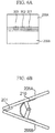
- FIG. 6A is a front view of a clip which holds the electrostatic speaker.
- FIG. 6B is a side view of the clip including plastic plates and electrodes.
- FIG. 7 is a plan view partly in section, showing the clip holding the electrostatic speaker with electrodes.
- FIG. 8 is an exploded perspective view showing a second variation of the electrostatic speaker equipped with conductive clips holding conductive layers.
- FIG. 9 is a front view showing a modification of the clip adapted to the conductive clips incorporated into the electrostatic speaker.
- FIG. 10 is a plan view showing a third variation of the electrostatic speaker.
- FIG. 11 is an exploded perspective view showing a fourth variation of the electrostatic speaker.
- FIG. 12 is a perspective view showing a fifth variation of the electrostatic speaker.
- FIG. 13 is a plan view showing a sixth variation of the electrostatic speaker.
- FIG. 14 is an exploded perspective view showing a seventh variation of the electrostatic speaker.
- FIG. 15 is a side view showing a basic configuration of an electrostatic speaker according to the present invention.
- FIG. 16 is a perspective view showing an eighth variation of the electrostatic speaker having the basic configuration.
- FIG. 17 is an exploded perspective view showing a further modification of the electrostatic speaker having the basic configuration.
- FIG. 1 is a perspective view showing an exterior appearance of an electrostatic speaker 1 according to an embodiment of the present invention.
- FIG. 2 is a cross-sectional view taken along line A-A in FIG. 1 , showing an interior structure of the electrostatic speaker 1 .
- FIG. 3 is an exploded perspective view of the electrostatic speaker 1 .
- the drawings employ a three-dimensional coordinate system consisting of an X-axis, a Y-axis, and a Z-axis which are perpendicular to each other.
- the X-axis direction is a right-left direction (or a width direction) of the electrostatic speaker 1 viewed in its front side; the Y-axis direction is a length direction (or a depth direction) of the electrostatic speaker 1 ; and the Z-axis direction is a height direction (or a vertical direction) of the electrostatic speaker 1 .
- the drawings are not necessarily illustrated with precise measurements; hence, dimensions of illustrations are modified for readers to easily grasp shapes of constituent elements.
- the electrostatic speaker 1 is constituted of a diaphragm 10 , electrodes 20 U and 20 L, and cushion materials 40 U and 40 L, wherein symbols “U” and “L” represent “upper” and “lower” respectively; hence, these symbols are omitted as being unnecessary.
- the diaphragm 10 includes a film (or a base material) 11 composed of PET (i.e. polyethylene terephthalate) or PP (i.e. polypropylene) and a conductive layer 12 .
- a conductive metal is deposited on one surface of the film 11 or a conductive coating is applied to one surface of the film 11 , thus forming the conductive layer 12 on the film 11 .
- the thickness of the diaphragm 10 ranges from several micrometers to several tens of micrometers.
- the diaphragm 1 has a rectangular shape in plan view, wherein a part of one side in the width direction (or the X-axis direction) is recessed to form a cutout having a predetermined width, which is cut into the diaphragm 1 in the length direction (or the Y-axis direction).
- the diaphragm 10 of the present embodiment is designed such that one surface of the film 11 is deposited with a conductive metal or applied with a conductive coating.
- a conductive metal or applied with a conductive coating.
- conductive metals on or apply conductive coating to both surfaces of the film 11 .
- the material of the film 11 of the diaphragm 1 is not necessarily limited to PET and PP; hence, it is possible to deposit a conductive metal on or apply a conductive coating to a film composed of another synthetic resin.
- the electrode 20 U includes a film (or a base material) 22 U composed of PET and a conductive layer 23 U.
- a conductive metal e.g. aluminum
- a plurality of through-holes is formed to run through the electrode 20 U from its surface to the backside.
- the drawings do not illustrate through-holes for the sake of simplicity.
- the electrode 20 U has a rectangular shape in plan view, wherein a part of one side in the width direction is recessed to form a cutout having a predetermined width, which is cut into the electrode 20 U in the length direction.
- the width of the cutout of the electrode 20 U is longer than the width of the cutout of the diaphragm 10 , while the length of the cutout of the electrode 20 U is identical to the length of the cutout of the diaphragm 10 .
- the electrode 20 U has bendability because it is constituted of a PET sheet having flexibility.
- the electrode 20 L includes a film (or a base material) 22 L composed of PET and a conductive layer 23 L.
- a conductive metal is deposited on or a conductive coating is applied to one surface of the film 22 L, thus forming the conductive layer 23 L.
- a plurality of through-holes (not shown) is formed to run through the electrode 20 L from its surface to the backside. Unlike the electrode 20 U, the electrode 20 L has no cutout.
- the electrodes 20 U and 20 L are each designed such that a conductive metal is deposited on or a conductive coating is applied to one surface of a base material; but this is not a restriction. It is possible to deposit conductive metals on or apply a conductive coating to both surfaces of a base material.
- the material used for the films 22 U and 22 L of the electrodes 20 U and 20 L is not limited to PET; hence, it is possible to use other synthetic resins, so that conductive metals are deposited on or a conductive coating is applied to films composed of other synthetic resins.
- the cushion materials 40 U and 40 L are each composed with cottons which are compressed under heating, so that they have permeability of air and sound therethrough.
- the cushion materials 40 U and 40 L having electrical insulating property and elasticity can be deformed due to an external force but easily restored in shape when an external force is removed.
- the cushion material 40 U has a rectangular shape in plan view, wherein a part of one side in the width direction is recessed to form a cutout which is cut into the cushion material 40 U in the length direction.
- the cushion material 40 L has a rectangular shape in plan view, wherein a part of one side in the width direction is recessed to form a cutout which is cut into the cushion material 40 L in the length direction.
- the position of the cutout of the cushion material 40 U precisely matches the position of the cutout of the electrode 20 U.
- the width and length of the cutout of the cushion material 40 U are equal to the width and length of the cutout of the electrode 20 U.
- the position of the cutout of the cushion material 40 L precisely matches the position of the cutout of the diaphragm 10 .
- the width and length of the cutout of the cushion material 40 L are equal to the width and length of the cutout of the diaphragm 10 .
- the diaphragm 10 is interposed between the cushion materials 40 U and 40 L such that the conductive layer 12 of the diaphragm 10 is attached to the lower surface of the cushion material 40 U while the lower surface of the diaphragm 10 is attached to the upper surface of the cushion material 40 L.
- the diaphragm 10 is bonded onto the cushion materials 40 U and 40 L via bonds applied to left/right edges (along the width direction) and front/rear edges (along the length direction) of the diaphragm 10 with bond margins of several millimeters measured inwardly from the corresponding edge. That is, the internal area of the diaphragm 10 inwardly of bond margins is not fixed to the cushion materials 40 U and 40 L.
- the conductive layer 23 L of the electrode 20 L is directed toward the diaphragm 10 and attached to the lower surface of the cushion material 40 L, while the film 22 U of the electrode 20 U is directed toward the diaphragm 10 and attached to the upper surface of the cushion material 40 U.
- the electrode 20 U and the cushion material 40 U are bonded together via bonds applied to left/right edges (along the width direction) and front/rear edges (along the length direction) of the electrode 20 U with bond margins of several millimeters measured inwardly from the corresponding edge, so that the internal area of the electrode 20 U inwardly of bond margins is not fixed to the cushion material 40 U.
- the electrode 20 L and the cushion material 40 L are bonded together via bonds applied to left/right edges (along the width direction) and front/rear edges (along the length direction) of the electrode 20 L with bond margins of several millimeters, so that the internal area of the electrode 20 L inwardly of bond margins is not fixed to the cushion material 40 L.
- FIG. 4 is a plan view of the electrostatic speaker 1 seeing through cutouts. Both the width of the cutout of the diaphragm 10 and the width of the cutout of the cushion material 40 L are smaller than the width of the cutout of the electrode 20 U and the width of the cutout of the cushion material 40 U; hence, the cutout of the diaphragm 10 and the cutout of the cushion material 40 L fall within the cutout of the electrode 20 U and the cutout of the cushion material 40 U in plan view.
- a part of the conductive layer 1 of the diaphragm 10 is exposed through the cutout of the cushion material 40 U and the cutout of the electrode 20 U, while a part of the conductive layer 23 L of the electrode 20 L is exposed through the cutout of the cushion material 40 L, the cutout of the diaphragm 10 , the cutout of the cushion material 40 U, and the cutout of the electrode 20 U.
- the electrostatic speaker 1 is coupled with a transformer 50 , an input unit 60 for inputting audio signals from an external device (not shown), and a drive unit 100 having a bias power source 70 for applying a DC bias voltage to the diaphragm 10 .
- the bias power source 70 is connected to the conductive layer 12 of the diaphragm 10 and a neutral point of the output side of the transformer 50 .
- An upper terminal of the output side of the transformer 50 is connected to the conductive layer 23 U of the electrode 20 U, while a lower terminal of the output side of the transformer 50 is connected to the conductive layer 23 L of the electrode 20 L.
- the input side of the transformer 50 is connected with the input unit 60 . In this configuration, when the input unit 60 receives an audio signal, the transformer 50 produces a voltage based on the audio signal, so that the voltage is applied to the conductive layers 23 U and 23 L of the electrodes 20 U and 20 L; hence, the electrostatic speaker 1 functions as a push-pull electrostatic speaker.
- the electrostatic speaker 1 is connected to the drive unit 100 via a clip 200 .
- FIG. 6A is a front view of the clip 200
- FIG. 6B is a side view of the clip 200 .
- the clip 200 includes rectangular electrodes 201 through 203 and a spring 210 .
- the clip 200 further includes plastic plates 205 A and 205 B which are assembled together and positioned opposite to each other. The electrodes 201 through 203 are fixed to the plastic plate 205 A.
- the electrode 201 is connected with a conducting wire (not shown) which is connected to one terminal of the output side of the transformer 50 whilst the electrode 203 is connected with a conducting wire (not shown) which is connected to another terminal of the output side of the transformer 50 .
- the electrode 202 is connected with a conducting wire (not shown) which is connected to the bias power source 70 .
- the clip 200 tightly holds the electrostatic speaker 1 at the cutouts as shown in FIG. 7 , the electrode 201 comes in contact with the conductive layer 23 U. Since the conductive layer 12 of the diaphragm 10 and the conductive layer 23 L of the electrode 20 L are exposed through the cutouts, the electrode 202 comes in contact with the conductive layer 12 whilst the electrode 203 comes in contact with the conductive layer 23 L.
- the transformer 50 correspondingly produces a voltage (corresponding to the audio signal), which is applied to the conductive layers 23 U and 23 L of the electrodes 20 U and 20 L via the electrodes 201 and 203 of the clip 200 .
- a potential difference occurs between the conductive layers 23 U and 23 L, an electrostatic force is induced so that the diaphragm 10 is attracted toward either the electrode 20 U or the electrode 20 L.
- the diaphragm 10 When the transformer 50 applies a positive voltage to the conductive layer 23 U while applying a negative voltage to the conductive layer 23 L in response to an audio signal input to the input unit 60 , the diaphragm 10 , whose conductive layer is already applied with a “positive” bias voltage from the bias power source 70 , is repelled by the “positively charged” conductive layer 23 U while being attracted toward the “negatively charged” conductive layer 23 L; hence, the diaphragm 10 is displaced toward the electrode 20 L.
- the diaphragm 10 is attracted toward the “negatively charged” conductive layer 23 U while being repelled by the “positively charged” conductive layer 23 L; hence, the diaphragm 10 is displaced toward the electrode 20 U.
- the diaphragm 10 is displaced (or bent) toward either the electrode 20 U or the electrode 20 L in response to audio signals, wherein the displacement direction is alternately changed to cause vibration.
- the diaphragm 10 produces sound based on vibration conditions (e.g. frequency, amplitude, and phase). Sound permeates through the cushion material 40 and the electrodes 20 U, 20 L, so that the electrostatic speaker 1 emits sound in the external space.
- the present embodiment is advantageous in that the electrostatic speaker 1 can be easily connected with the drive unit 100 by use of the clip 200 simply holding the electrostatic speaker 1 , thus easily transmitting signals from the drive unit 100 to the conductive layers 12 , 23 U, and 23 L.
- the present embodiment allows users to easily disconnect the drive unit 100 from the electrostatic speaker 1 by simply detaching the clip 200 from the electrostatic speaker 1 . This realizes portability of the electrostatic speaker 1 .
- the electrostatic speaker 1 of the present embodiment does not need conductive wires; hence, when the electrostatic speaker 1 is not used, it can be folded without problem and kept in a safe place.
- a thin plate composed of a synthetic resin can be attached to a clipped region of the electrostatic speaker 1 being tightly held by the clip 200 , thus reinforcing the cutouts.
- a conductive tape can be attached to a contact region of the electrostatic speaker 1 which is brought into contact with the electrodes 201 through 203 , thus reinforcing the contact region of the electrostatic speaker 1 .
- FIG. 9 is a front view of the plastic plate 205 A of the clip 200 which is modified in connection with the clip 300 .
- the plastic plate 205 A has recesses 206 A through 206 C whose depths are larger than the thicknesses of the electrodes 201 through 203 . That is, the electrodes 201 through 203 are disposed inside the recesses 206 A through 206 C of the plastic plate 205 A.
- the clip 300 holding the conductive layer 23 U enters into the recess 206 A in contact with the electrode 201 ; the clip 300 holding the conductive layer 12 enters into the recess 206 B in contact with the electrode 202 ; and the clip 300 holding the conductive layer 23 L enters into the recess 206 C in contact with the electrode 203 . Since the clips 300 are engaged with the recesses 206 A through 206 C, the clips 300 are hardly dislocated from the electrostatic speaker 1 .
- the conductive layers 12 , 23 U and 23 L are partially exposed in plan view and positioned adjacently; but the exposed portions of the conductive layers 12 , 23 U and 23 L do not need to be positioned adjacently.
- FIG. 10 is a plan view of the electrostatic speaker 1 according to a third variation, in which the exposed portion of the conductive layer 12 is separated from the exposed portion of the conductive layer 23 L.
- the clip 200 needs to be divided into three pieces, i.e. a first clip having the electrode 201 disposed in contact with the conductive layer 23 U, a second clip having the electrode 202 disposed in contact with the conductive layer 12 , and a third clip having the electrode 203 disposed in contact with the conductive layer 23 L.
- the electrostatic speaker 1 is connected with the drive unit 100 via the clip 200 having the electrodes 201 through 203 ; but this is not a restriction.
- FIG. 11 is an exploded perspective view showing a fourth variation of the electrostatic speaker 1 constituted of an electrode 20 UA, a diaphragm 10 A, and an electrode 20 LA, in which the cushion materials 40 U and 40 L are not illustrated.
- the electrode 20 UA has two cutouts which are formed along the width direction in the conductive layer 23 U.
- the diaphragm 10 A has two cutouts which are formed along the width direction in the conductive layer 12 .
- the electrode 20 LA has two cutouts which are formed along the width direction in the conductive layer 23 L. All the cutouts have the same width (along the width direction) and the same length (along the length direction) although they are formed at different positions.
- the cutouts are formed in only the conductive layers 12 , 23 U and 23 L, whilst no cutouts are formed in the films 11 , 22 U and 22 L.
- two cutouts of the conductive layer 23 U are horizontally disposed and isolated with half the width of cutout therebetween.
- the two cutouts of the conductive layer 12 are horizontally disposed and isolated with a half the width of each cutout.
- two cutouts of the conductive layer 12 are positionally shifted half the width of cutout rightwards from the two cutouts of the conductive layer 23 U.
- two cutouts of the conductive layer 23 L are positionally shifted half the width of cutout rightwards from the two cutouts of the conductive layer 12 .
- the clip 200 needs to be adapted to the electrostatic speaker 1 including the diaphragm 10 A, the electrodes 20 UA and 20 LA shown in FIG. 11 by way of electrodes 201 A to 203 A having needle shapes.
- the electrode 201 A is put into a point P 1 ; the electrode 202 A pierces into a point P 2 ; and the electrode 203 A is put into a point P 3 .
- the electrode 201 A runs through points P 1 , P 1 ′, and P 1 ′′, wherein the point P 1 has the conductive layer 23 U whilst the points P 1 ′ and P 1 ′′ do not have the conductive layers 12 and 23 L due to the cutouts; hence, the electrode 201 A comes in contact with the conductive layer 23 U but does not come in contact with the conductive layers 12 and 23 L. That is, a voltage of the electrode 201 A is selectively applied to the conductive layer 23 U.
- the electrode 202 A runs through points P 2 , P 2 ′ and P 2 ′′, wherein the point P 2 does not have the conductive layer 23 U due to the cutout, the point P 2 ′ has the conductive layer 12 , and the point P 2 ′′ does not have the conductive layer 23 L due to the cutout; hence, the electrode 202 A comes in contact with the conductive layer 12 but does not come in contact with the conductive layers 23 U and 23 L. That is, a voltage of the electrode 202 A is selectively applied to the conductive layer 12 .
- the electrode 203 A pierces through points P 3 , P 3 ′, and P 3 ′′, wherein the point P 3 does not have the conductive layer 23 U due to the cutout, the point P 3 ′ does not have the conductive layer 12 due to the cutout, and the point P 3 ′′ has the conductive layer 23 L; hence, the electrode 203 A does not come in contact with the conductive layers 23 U and 12 but comes in contact with the conductive layer 23 L. That is, a voltage of the electrode 203 A is selectively applied to the conductive layer 23 L.
- the fourth variation is able to transmit signals of the drive unit 100 to the electrostatic speaker 1 by using the clip 200 simply holding the electrostatic speaker 1 .
- FIG. 12 is a perspective view showing a fifth variation of the electrostatic speaker 1 , in particular focusing on an electrode 20 UB.
- the electrode 20 UB has a single cutout and two islands disposed in connection with the points P 2 and P 3 , wherein two islands are isolated parts of the conductive layer 23 U whose surrounding areas (having predetermined widths) are cut out.
- the diaphragm 10 and the electrode 20 L can be modified such that the conductive layers 12 and 23 L are removed in cutting margins surrounding selected points.
- FIG. 13 is a plan view showing a sixth variation of the electrostatic speaker 1 , in particular focusing on the conductive layer 23 U of the electrode 20 U. As shown in FIG. 13 , rectangular holes are formed to run through the electrode 20 U, the diaphragm 10 , and the cushion materials 40 U and 40 L, wherein the conductive layers 12 and 23 L are exposed in the internal area inwardly of an edge of the electrostatic speaker 1 .
- the electrodes 20 U and 20 L can be composed of conductive cloths or nonwoven fabrics having conductivity.
- the electrodes 20 U and 20 L can be composed of punching metals.
- FIG. 14 shows a seventh variation of the electrostatic speaker 1 constituted of electrodes 20 UC, 20 LC, a diaphragm 10 C, and cushion materials 40 UC, 40 LC.
- the electrode 20 UC has a single cutout
- the cushion material 40 UC has a single cutout
- the diaphragm 10 C has two cutouts which are separated from each other
- the cushion material 40 LC has two cutouts which are separated from each other
- the electrode 20 LC has a single cutout.
- the electrode 201 comes in contact with a region Al proximate to a cutout on the conductive layer of the electrode 20 UC; the electrode 202 comes in contact with a region A 2 disposed between two cutouts on the conductive layer of the diaphragm 10 C; and the electrode 203 comes in contact with a region A 3 proximate to a cutout on the conductive layer of the electrode 20 LC. Due to the cutouts of the diaphragm 10 C and the electrode 20 LC just below the region A 1 of the electrode 20 UC, the electrode 201 of the clip 200 selectively comes in contact with the conductive layer of the electrode 20 UC.
- the electrode 202 of the clip 200 selectively comes in contact with the conductive layer of the diaphragm 10 C. Due to the cutouts of the electrode 20 UC and the diaphragm 10 C just above the region A 3 of the electrode 20 LC, the electrode 203 of the clip 200 selectively comes in contact with the conductive layer of the electrode 20 LC.
- the present invention has a basic configuration of an electrostatic speaker including a first conductive film 101 , a first insulating layer 102 , and a second conductive film 103 which are sequentially laminated in a vertical direction as shown in FIG. 15 .
- One of the first conductive film 101 and the second conductive film 103 serves as a diaphragm whilst the other serves as an electrode.
- FIG. 16 shows that a hole or cutout for supplying power to the second conductive film 103 is formed in the first conductive film 101 and the first insulating 102 so as to partially expose the second conductive film 103 .
- FIG. 17 shows that holes or cutout are formed in the first conductive film 101 and the second conductive film 103 , thus supplying power to the second conductive film 103 .
- a hole or cutout of the first conductive film 101 is positionally shifted from a hole or cutout of the second conductive film 103 in the width direction in plan view.
- the electrode 301 pricks on a point P 11 whilst the electrode 302 pierces between points P 12 and P 12 ′.
- the electrode 301 comes in contact with the first conductive film 101 but does not come in contact with the second conductive film 103 due to its hole or cutout, thus selectively supplying power to the first conductive film 101 .
- the electrode 302 does not come in contact with the first conductive film 101 due to its hole or cutout but comes in contact with the second conductive film 103 , thus selectively supplying power to the second conductive film 103 .
Landscapes
- Physics & Mathematics (AREA)
- Engineering & Computer Science (AREA)
- Acoustics & Sound (AREA)
- Signal Processing (AREA)
- Electrostatic, Electromagnetic, Magneto- Strictive, And Variable-Resistance Transducers (AREA)
Applications Claiming Priority (2)
| Application Number | Priority Date | Filing Date | Title |
|---|---|---|---|
| JP2009-226383 | 2009-09-30 | ||
| JP2009226383 | 2009-09-30 |
Publications (2)
| Publication Number | Publication Date |
|---|---|
| US20110075869A1 US20110075869A1 (en) | 2011-03-31 |
| US8666097B2 true US8666097B2 (en) | 2014-03-04 |
Family
ID=43333013
Family Applications (1)
| Application Number | Title | Priority Date | Filing Date |
|---|---|---|---|
| US12/891,692 Expired - Fee Related US8666097B2 (en) | 2009-09-30 | 2010-09-27 | Electrostatic speaker |
Country Status (4)
| Country | Link |
|---|---|
| US (1) | US8666097B2 (de) |
| EP (1) | EP2312868A3 (de) |
| JP (1) | JP2011097580A (de) |
| CN (1) | CN102036154B (de) |
Cited By (2)
| Publication number | Priority date | Publication date | Assignee | Title |
|---|---|---|---|---|
| US20130108087A1 (en) * | 2010-07-12 | 2013-05-02 | Yamaha Corporation | Electrostatic loudspeaker |
| US12253391B2 (en) | 2018-05-24 | 2025-03-18 | The Research Foundation For The State University Of New York | Multielectrode capacitive sensor without pull-in risk |
Families Citing this family (4)
| Publication number | Priority date | Publication date | Assignee | Title |
|---|---|---|---|---|
| GB2522931A (en) | 2014-02-11 | 2015-08-12 | Warwick Audio Technologies Ltd | Improved electrostatic transducer |
| GB2522932A (en) | 2014-02-11 | 2015-08-12 | Warwick Audio Technologies Ltd | Improved electrostatic transducer |
| GB201906425D0 (en) | 2019-05-07 | 2019-06-19 | Warwick Acoustics Ltd | Electrostatic transducer and diaphragm |
| CN113747298B (zh) * | 2021-08-09 | 2023-09-08 | 昆山海菲曼科技集团股份有限公司 | 一种静电耳机 |
Citations (13)
| Publication number | Priority date | Publication date | Assignee | Title |
|---|---|---|---|---|
| US3935397A (en) | 1974-01-28 | 1976-01-27 | Electronic Industries, Inc. | Electrostatic loudspeaker element |
| US5392358A (en) | 1993-04-05 | 1995-02-21 | Driver; Michael L. | Electrolytic loudspeaker assembly |
| US5889873A (en) * | 1996-03-11 | 1999-03-30 | Tdk Corporation | Piezoelectric acoustic transducer |
| US6434245B1 (en) | 1999-01-25 | 2002-08-13 | Claus Zimmermann | Compound electrolytic loudspeaker assembly |
| US6825593B2 (en) * | 2000-04-19 | 2004-11-30 | Murata Manufacturing Co., Ltd. | Piezoelectric type electric acoustic converter |
| CN1757261A (zh) | 2003-03-04 | 2006-04-05 | 美商楼氏电子有限公司 | 驻极体电容式传声器 |
| EP1860913A2 (de) | 2006-05-24 | 2007-11-28 | Yamaha Corporation | Elektrostatischer Lautsprecher |
| JP2007318554A (ja) | 2006-05-26 | 2007-12-06 | Yamaha Corp | 静電型スピーカ |
| JP2008227832A (ja) | 2007-03-12 | 2008-09-25 | Yamaha Corp | 静電型スピーカ |
| US20090016552A1 (en) * | 2006-01-03 | 2009-01-15 | Warwick Audio Technologies Limited | Electrostatic Loudspeakers |
| US20090034761A1 (en) * | 2007-08-02 | 2009-02-05 | Takao Nakaya | Electrostatic speaker |
| US8000483B2 (en) * | 2006-01-03 | 2011-08-16 | Transparent Sound Technology B.V. | Electrostatic loudspeaker systems and methods |
| US8243966B2 (en) * | 2008-12-18 | 2012-08-14 | Industrial Technology Research Institute | Assembly structure of a flat speaker |
Family Cites Families (9)
| Publication number | Priority date | Publication date | Assignee | Title |
|---|---|---|---|---|
| JPS5341409Y2 (de) * | 1973-04-23 | 1978-10-05 | ||
| JPS5962679U (ja) * | 1982-10-20 | 1984-04-24 | 株式会社リコー | 電気機器接続具 |
| JPH01236708A (ja) * | 1988-03-16 | 1989-09-21 | Sharp Corp | マイクロ波コンバータ |
| JP2562036Y2 (ja) * | 1992-10-27 | 1998-02-04 | 日本メクトロン株式会社 | 給配電母線の接続端子構造 |
| JP2973896B2 (ja) * | 1995-10-18 | 1999-11-08 | 住友電装株式会社 | 平型導体配線板の回路導体の接続部材 |
| JP2002010393A (ja) * | 2000-04-19 | 2002-01-11 | Murata Mfg Co Ltd | 圧電型電気音響変換器 |
| JP2008054154A (ja) * | 2006-08-28 | 2008-03-06 | Univ Waseda | 平面スピーカ |
| JP4830933B2 (ja) * | 2007-03-19 | 2011-12-07 | ヤマハ株式会社 | 静電型スピーカ |
| JP5205097B2 (ja) | 2007-06-18 | 2013-06-05 | 旭サナック株式会社 | 多液混合装置 |
-
2010
- 2010-09-27 US US12/891,692 patent/US8666097B2/en not_active Expired - Fee Related
- 2010-09-27 EP EP10010909.9A patent/EP2312868A3/de not_active Withdrawn
- 2010-09-28 CN CN201010502360.3A patent/CN102036154B/zh not_active Expired - Fee Related
- 2010-09-29 JP JP2010219461A patent/JP2011097580A/ja active Pending
Patent Citations (14)
| Publication number | Priority date | Publication date | Assignee | Title |
|---|---|---|---|---|
| US3935397A (en) | 1974-01-28 | 1976-01-27 | Electronic Industries, Inc. | Electrostatic loudspeaker element |
| US5392358A (en) | 1993-04-05 | 1995-02-21 | Driver; Michael L. | Electrolytic loudspeaker assembly |
| US5889873A (en) * | 1996-03-11 | 1999-03-30 | Tdk Corporation | Piezoelectric acoustic transducer |
| US6434245B1 (en) | 1999-01-25 | 2002-08-13 | Claus Zimmermann | Compound electrolytic loudspeaker assembly |
| US6825593B2 (en) * | 2000-04-19 | 2004-11-30 | Murata Manufacturing Co., Ltd. | Piezoelectric type electric acoustic converter |
| US7184563B2 (en) | 2003-03-04 | 2007-02-27 | Knowles Electronics Llc. | Electret condenser microphone |
| CN1757261A (zh) | 2003-03-04 | 2006-04-05 | 美商楼氏电子有限公司 | 驻极体电容式传声器 |
| US20090016552A1 (en) * | 2006-01-03 | 2009-01-15 | Warwick Audio Technologies Limited | Electrostatic Loudspeakers |
| US8000483B2 (en) * | 2006-01-03 | 2011-08-16 | Transparent Sound Technology B.V. | Electrostatic loudspeaker systems and methods |
| EP1860913A2 (de) | 2006-05-24 | 2007-11-28 | Yamaha Corporation | Elektrostatischer Lautsprecher |
| JP2007318554A (ja) | 2006-05-26 | 2007-12-06 | Yamaha Corp | 静電型スピーカ |
| JP2008227832A (ja) | 2007-03-12 | 2008-09-25 | Yamaha Corp | 静電型スピーカ |
| US20090034761A1 (en) * | 2007-08-02 | 2009-02-05 | Takao Nakaya | Electrostatic speaker |
| US8243966B2 (en) * | 2008-12-18 | 2012-08-14 | Industrial Technology Research Institute | Assembly structure of a flat speaker |
Non-Patent Citations (2)
| Title |
|---|
| Chinese Office Action issued for corresponding application CN 201010502360.3, mailing date Jan. 23, 2013. (with attached English translation). |
| European Search Report issued for corresponding application EP 10 01 0909, mailing date Dec. 3, 2013. |
Cited By (3)
| Publication number | Priority date | Publication date | Assignee | Title |
|---|---|---|---|---|
| US20130108087A1 (en) * | 2010-07-12 | 2013-05-02 | Yamaha Corporation | Electrostatic loudspeaker |
| US8983099B2 (en) * | 2010-07-12 | 2015-03-17 | Yamaha Corporation | Electrostatic loudspeaker |
| US12253391B2 (en) | 2018-05-24 | 2025-03-18 | The Research Foundation For The State University Of New York | Multielectrode capacitive sensor without pull-in risk |
Also Published As
| Publication number | Publication date |
|---|---|
| US20110075869A1 (en) | 2011-03-31 |
| EP2312868A2 (de) | 2011-04-20 |
| JP2011097580A (ja) | 2011-05-12 |
| EP2312868A3 (de) | 2014-01-01 |
| CN102036154A (zh) | 2011-04-27 |
| CN102036154B (zh) | 2014-06-25 |
Similar Documents
| Publication | Publication Date | Title |
|---|---|---|
| US20110075869A1 (en) | Electrostatic speaker | |
| US20130129121A1 (en) | Electrostatic loudspeaker and method of producing electrostatic loudspeaker | |
| KR101445503B1 (ko) | 정전형 스피커 | |
| US20110255721A1 (en) | Flat speaker unit and speaker device therewith | |
| KR20080049639A (ko) | 컨덴서 마이크로폰의 제조 방법 및 컨덴서 마이크로폰 | |
| JP2017050709A (ja) | 静電型スピーカ | |
| EP1173043A2 (de) | Piezoelektrischer Lautsprecher | |
| CN107564505B (zh) | 一种压电振动发声模块 | |
| US20110110542A1 (en) | Piezoelectric exciter and piezoelectric exciter unit | |
| CN104205387A (zh) | 压电振动元件、使用其的压电振动装置以及便携终端 | |
| US10860109B2 (en) | Tactile presentation device | |
| JP5545091B2 (ja) | 静電型スピーカ | |
| JP2009038637A (ja) | 静電型スピーカ | |
| JP2010062622A (ja) | 静電型スピーカ | |
| JP5760878B2 (ja) | 静電型の電気音響変換器 | |
| JP5423289B2 (ja) | 静電型スピーカ | |
| WO2016060148A1 (ja) | 固定極及び電気音響変換器 | |
| US20140321676A1 (en) | Electrostatic speaker | |
| JP6379984B2 (ja) | 固定極及び電気音響変換器 | |
| JP6040545B2 (ja) | 静電型トランスデューサ | |
| JP5760879B2 (ja) | 静電型の電気音響変換器 | |
| JP5056604B2 (ja) | 静電型スピーカ | |
| JP2012080531A (ja) | 静電型の電気音響変換器 | |
| JP5304575B2 (ja) | 静電型スピーカ | |
| CN103959820B (zh) | 静电扬声器 |
Legal Events
| Date | Code | Title | Description |
|---|---|---|---|
| AS | Assignment |
Owner name: YAMAHA CORPORATION, JAPAN Free format text: ASSIGNMENT OF ASSIGNORS INTEREST;ASSIGNORS:ICHIKAWA, HIROMI;MATSUBARA, YOSHIKATSU;REEL/FRAME:025048/0455 Effective date: 20100910 |
|
| FEPP | Fee payment procedure |
Free format text: PAYOR NUMBER ASSIGNED (ORIGINAL EVENT CODE: ASPN); ENTITY STATUS OF PATENT OWNER: LARGE ENTITY Free format text: PAYER NUMBER DE-ASSIGNED (ORIGINAL EVENT CODE: RMPN); ENTITY STATUS OF PATENT OWNER: LARGE ENTITY |
|
| FEPP | Fee payment procedure |
Free format text: MAINTENANCE FEE REMINDER MAILED (ORIGINAL EVENT CODE: REM.) |
|
| LAPS | Lapse for failure to pay maintenance fees |
Free format text: PATENT EXPIRED FOR FAILURE TO PAY MAINTENANCE FEES (ORIGINAL EVENT CODE: EXP.) |
|
| STCH | Information on status: patent discontinuation |
Free format text: PATENT EXPIRED DUE TO NONPAYMENT OF MAINTENANCE FEES UNDER 37 CFR 1.362 |
|
| FP | Lapsed due to failure to pay maintenance fee |
Effective date: 20180304 |