US8638065B2 - Battery pack and battery pack system - Google Patents
Battery pack and battery pack system Download PDFInfo
- Publication number
- US8638065B2 US8638065B2 US13/084,227 US201113084227A US8638065B2 US 8638065 B2 US8638065 B2 US 8638065B2 US 201113084227 A US201113084227 A US 201113084227A US 8638065 B2 US8638065 B2 US 8638065B2
- Authority
- US
- United States
- Prior art keywords
- battery
- voltage
- battery module
- battery pack
- module
- Prior art date
- Legal status (The legal status is an assumption and is not a legal conclusion. Google has not performed a legal analysis and makes no representation as to the accuracy of the status listed.)
- Expired - Fee Related, expires
Links
Images


Classifications
-
- H—ELECTRICITY
- H01—ELECTRIC ELEMENTS
- H01M—PROCESSES OR MEANS, e.g. BATTERIES, FOR THE DIRECT CONVERSION OF CHEMICAL ENERGY INTO ELECTRICAL ENERGY
- H01M10/00—Secondary cells; Manufacture thereof
- H01M10/42—Methods or arrangements for servicing or maintenance of secondary cells or secondary half-cells
- H01M10/44—Methods for charging or discharging
- H01M10/441—Methods for charging or discharging for several batteries or cells simultaneously or sequentially
-
- H—ELECTRICITY
- H01—ELECTRIC ELEMENTS
- H01M—PROCESSES OR MEANS, e.g. BATTERIES, FOR THE DIRECT CONVERSION OF CHEMICAL ENERGY INTO ELECTRICAL ENERGY
- H01M10/00—Secondary cells; Manufacture thereof
- H01M10/42—Methods or arrangements for servicing or maintenance of secondary cells or secondary half-cells
- H01M10/44—Methods for charging or discharging
- H01M10/443—Methods for charging or discharging in response to temperature
-
- H—ELECTRICITY
- H01—ELECTRIC ELEMENTS
- H01M—PROCESSES OR MEANS, e.g. BATTERIES, FOR THE DIRECT CONVERSION OF CHEMICAL ENERGY INTO ELECTRICAL ENERGY
- H01M10/00—Secondary cells; Manufacture thereof
- H01M10/42—Methods or arrangements for servicing or maintenance of secondary cells or secondary half-cells
- H01M10/46—Accumulators structurally combined with charging apparatus
-
- H—ELECTRICITY
- H02—GENERATION; CONVERSION OR DISTRIBUTION OF ELECTRIC POWER
- H02J—CIRCUIT ARRANGEMENTS OR SYSTEMS FOR SUPPLYING OR DISTRIBUTING ELECTRIC POWER; SYSTEMS FOR STORING ELECTRIC ENERGY
- H02J7/00—Circuit arrangements for charging or depolarising batteries or for supplying loads from batteries
- H02J7/0013—Circuit arrangements for charging or depolarising batteries or for supplying loads from batteries acting upon several batteries simultaneously or sequentially
- H02J7/0014—Circuits for equalisation of charge between batteries
-
- H—ELECTRICITY
- H01—ELECTRIC ELEMENTS
- H01M—PROCESSES OR MEANS, e.g. BATTERIES, FOR THE DIRECT CONVERSION OF CHEMICAL ENERGY INTO ELECTRICAL ENERGY
- H01M10/00—Secondary cells; Manufacture thereof
- H01M10/05—Accumulators with non-aqueous electrolyte
- H01M10/052—Li-accumulators
- H01M10/0525—Rocking-chair batteries, i.e. batteries with lithium insertion or intercalation in both electrodes; Lithium-ion batteries
-
- H—ELECTRICITY
- H02—GENERATION; CONVERSION OR DISTRIBUTION OF ELECTRIC POWER
- H02J—CIRCUIT ARRANGEMENTS OR SYSTEMS FOR SUPPLYING OR DISTRIBUTING ELECTRIC POWER; SYSTEMS FOR STORING ELECTRIC ENERGY
- H02J7/00—Circuit arrangements for charging or depolarising batteries or for supplying loads from batteries
- H02J7/0029—Circuit arrangements for charging or depolarising batteries or for supplying loads from batteries with safety or protection devices or circuits
- H02J7/00302—Overcharge protection
-
- Y—GENERAL TAGGING OF NEW TECHNOLOGICAL DEVELOPMENTS; GENERAL TAGGING OF CROSS-SECTIONAL TECHNOLOGIES SPANNING OVER SEVERAL SECTIONS OF THE IPC; TECHNICAL SUBJECTS COVERED BY FORMER USPC CROSS-REFERENCE ART COLLECTIONS [XRACs] AND DIGESTS
- Y02—TECHNOLOGIES OR APPLICATIONS FOR MITIGATION OR ADAPTATION AGAINST CLIMATE CHANGE
- Y02E—REDUCTION OF GREENHOUSE GAS [GHG] EMISSIONS, RELATED TO ENERGY GENERATION, TRANSMISSION OR DISTRIBUTION
- Y02E60/00—Enabling technologies; Technologies with a potential or indirect contribution to GHG emissions mitigation
- Y02E60/10—Energy storage using batteries
Definitions
- the present invention relates to a battery pack usable as a power source of an electric device, and a battery pack system configured to include therein the battery pack and the electric device, and more particularly to such a battery pack and such a battery pack system each of which includes therein a battery cell group of a plurality of serially-interconnected battery cells or a serial array of battery cells, wherein each battery cell is in the form of a rechargeable battery such as a Li-ion battery.
- An electric device is primarily powered by an AC voltage supplied from a commercial power source, or a DC voltage supplied from battery cells. As one of performance characteristics required for an electric device, a high output is focused on. To drive the high-output electric device with energy stored in a battery pack, the battery pack is required to output a high voltage.
- An example of such a conventional battery pack or such a battery pack system is disclosed in Japanese Patent Nos. 4104648 and 4216898.
- the 108V Li-ion battery pack for use in the battery pack system is constructed with thirty (30) Li-ion battery cells interconnected in series, each of which has 3.6 volts.
- the conventional battery pack has a drawback that a high voltage of 108 volts at a maximum can frequently apply to inner segments within the battery pack, such as locations between the battery cells having mutually different voltages, locations between voltage monitor wires, space between the voltage monitor wires and the battery cells, and locations between discharging terminals having opposite polarities.
- the present inventor has proposed the following approach:
- a battery pack 200 is constructed to include: a battery module group of three (3) battery modules 100 interconnected in series, which generate a total voltage of 108 volts; and a discharge output terminal 201 for supplying a total voltage of 108 volts to an electric device 300 , with these components housed within a casing, wherein each battery module 100 generating 36 volts is a serial array of ten (10) Li-ion battery cells generating 36 volts.
- the electric device 300 houses a load controller 305 which acts as a discharge controller controls the state (i.e., active and/or inactive) of a load device 304 within the electric device 300 , based on a detection result of at least one of a voltage, a temperature and a current, of at least one of the battery cells within the battery pack 200 .
- a load controller 305 acts as a discharge controller controls the state (i.e., active and/or inactive) of a load device 304 within the electric device 300 , based on a detection result of at least one of a voltage, a temperature and a current, of at least one of the battery cells within the battery pack 200 .
- the load controller 305 shifts the state of each battery module 100 from an output state (i.e., an active state) to a stop state (i.e., an inactive state).
- an output state i.e., an active state
- a stop state i.e., an inactive state
- the battery cells within the battery pack 200 are electrically isolated or disconnected from each other. Therefore, the number of battery cells which are serially interconnected, has reduced to ten (10), which is smaller than the total number (thirty (30)) of the battery cells belonging to the battery cell group or the battery pack 200 .
- the load controller 305 must be prepared for upcoming possible restart of power supply to the electric device 300 , during the above-described stop state in which the battery cells within the battery pack 200 are electrically isolated or disconnected from each other.
- a backup power supply 309 with an electricity storage device is disposed within the electric device 300 , to thereby allow the load controller 305 to keep working by electricity supplied from the electricity storage.
- the backup power supply 309 operates, such that, in an active state of the electric device 300 , that is, a state in which the battery cells within the battery pack 200 are electrically connected to each other for electric conduction, the backup power supply 309 receives electricity from the battery cell group, and, using the received electricity, the backup power supply 309 charges the electricity storage device.
- the backup power supply 309 operates, such that, in an inactive state of the electric device 300 , that is, a state in which the battery cells within the battery pack 200 are electrically disconnected from each other for electric isolation, the backup power supply 309 allows the electricity storage device to discharge electric energy that has been stored in the electricity storage device.
- the electric energy discharged from the electricity storage device is consumed by the load controller 305 to detect the state of the battery cells within the battery pack 200 and, on demand in the future, to bring the battery cells of the battery cell group into a conduction state in which the battery cells are electrically connected to each other for electric conduction.
- the designated battery cell has a reduced residual amount of charge relative to that of each of the rest of the battery cells within the battery pack 200 , resulting in capacity (or charge) imbalance among the battery cells.
- the capacity imbalance can easily cause a reduction in the life time of the battery cells, a reduction in the run time of the electric device, and so on. Notably, the longer the electric device 300 is kept inactive, the larger the capacity imbalance.
- the invention has been created to provide a battery pack including a discharge controller, or a battery pack system including an electric device, a battery pack usable as a power source of the electric device, and a discharge controller controlling the discharge function of the battery pack, which prevents high voltages from being frequently impressed onto inner segments of the battery pack, and which allows the discharge controller to successfully restart even after the battery pack has kept stopping power supply to the discharge controller for a long term, while limiting a cost increase.
- each one of the selected modes of the invention in such a dependent form as to depend from the other mode or modes does not exclude a possibility of the technological features in a dependent-form mode to become independent of those in the corresponding depended mode or modes and to be removed therefrom. It should be interpreted that the technological features in a dependent-form mode is allowed to become independent according to the nature of the corresponding technological features where appropriate:
- a battery pack usable as a power source of an electric device comprising:
- a battery module group in which a plurality of battery modules are interconnected in series;
- each battery module is configured to include a battery cell group in which a plurality of battery cells are interconnected in series,
- the battery pack further comprising:
- a discharge controller configured to control the discharge power which is supplied from the battery module group to the electric device
- an output voltage modulator configured to modulate a module output voltage of each battery module between a high voltage and a low voltage which is higher than zero and lower than the high voltage, depending on an instruction signal from the discharge controller
- the electric device is configured to include a load device
- the load device operates by the discharge power of the battery module group when each battery module outputs the high voltage, and does not operate by the discharge power of the battery module group when each battery module outputs the low voltage, and
- the discharge controller operates by the battery module group, irrespective of whether each battery module outputs the high voltage or the low voltage.
- the “output voltage modulator” may be implemented in an exemplary arrangement in which the modulator modulates the output voltage of the battery module to not only the high voltage and the low voltage, but also an additional voltage whose level is different from those of the high voltage and the low voltage.
- the “discharge controller” may be disposed within the battery pack, within the electric device, or so as to span both of them. This is applicable to the “output voltage modulator.”
- an example of the “discharge controller” is constructed to include at least the function of shifting the battery pack, between a conduction state in which the discharge output terminal of the battery pack is electrically connected with the electric device for electric conduction, and an isolation state in which the discharge output terminal is electrically disconnected from the electrical device. Still further, the “discharge controller” is constructed such that, the output power of the battery module group (i.e., the output power of the battery pack), after conversion, is supplied to the discharge controller, and the discharge controller is activated by the supplied power.
- the output power of the battery module group i.e., the output power of the battery pack
- a switching device which is connected with a current path allowing a current to flow to the battery module group and the discharge output terminal, and which varies between an ON state and an OFF state, in response to a control signal;
- switching-control circuitry configured to perform switching control for the switching device, by supplying the control signal with a variable duty ratio, to the switching device, and to control the control signal such that the duty ratio varies between when the module output voltage is equal to the high voltage and when the module output voltage is equal to the low voltage.
- a switching device which is connected with a current path allowing a current to flow to the battery module group and the discharge output terminal, and which varies between an ON state and an OFF state, in response to a control signal;
- a voltage divider connected to the battery cell group in parallel, per each battery module, and configured to selectively divide a total voltage of the battery cells that belong to the battery cell group, to produce a fractional voltage of the total voltage, such that, when the switching device is in the ON state, the module output voltage is equal to the total voltage, and when the switching device is in the OFF state, the module output voltage is equal to the fractional voltage.
- a battery pack system having an electric device and a battery pack usable as a power source of the electric device comprising:
- a battery module group in which a plurality of battery modules are interconnected in series;
- each battery module is configured to include a battery cell group in which a plurality of battery cells are interconnected in series,
- the battery pack system further comprising:
- a discharge controller configured to control the discharge power is supplied from the battery module group to the electric device
- an output voltage modulator configured to modulate a module output voltage of each battery module between a high voltage and a low voltage which is higher than zero and lower than the high voltage, depending on an instruction signal from the discharge controller, wherein
- the high voltage and the low voltage are set to allow a load device of the electric device to operate by the discharge power of the battery module group when each battery module outputs the high voltage, and to allow the load device not to operate by the discharge power of the battery module group when each battery module outputs the low voltage, and
- the discharge controller operates by the battery module group, irrespective of whether each battery module outputs the high voltage or the low voltage.
- a switching device which is connected with a current path allowing a current to flow to the battery module group and the discharge output terminal, and which varies between an ON state and an OFF state, in response to a control signal;
- switching-control circuitry configured to perform switching control for the switching device, by supplying the control signal with a variable duty ratio, to the switching device, and to control the control signal such that the duty ratio varies between when the module output voltage is equal to the high voltage and when the module output voltage is equal to the low voltage.
- a switching device which is connected with a current path allowing a current to flow to the battery module group and the discharge output terminal, and which varies between an ON state and an OFF state, in response to a control signal;
- a voltage divider connected to the battery cell group in parallel, per each battery module, and configured to selectively divide a total voltage of the battery cells that belong to the battery cell group, to produce a fractional voltage of the total voltage, such that, when the switching device is in the ON state, the module output voltage is equal to the total voltage, and when the switching device is in the OFF state, the module output voltage is equal to the fractional voltage.
- the above-described battery pack or battery pack system would allow, when the discharge controller within the battery pack system or the battery pack stops supply of electricity from the battery pack to the load device of the electric device, an actual output voltage of the battery cell group, in which the battery cells are interconnected in series for electric conduction, to have a lower voltage than that of the battery cell group when the electricity is supplied from the battery pack to the load device of the electric device. Therefore, the above-described battery pack or battery pack system would reduce how often a high voltage is impressed onto inner segments within the battery pack system or the battery pack, and prevents electric breakdown within the battery pack and electrical leakage to outside of the battery pack due to introduction of foreign matters from outside of the battery pack, resulting in improved electric-isolation reliability of the battery pack system or the battery pack.
- the above-described battery pack or battery pack system would allow voltage modulation or transformation to be performed not directly for the total output voltage of the battery module group, but separately for the individual output voltages of the battery modules which together constitute the battery module group. Therefore, the above-described battery pack or battery pack system would reduce how often a high voltage is impressed onto inner segments within the battery pack system or the battery pack, so as to be fewer than when the voltage modulation is performed directly for the total output voltage of the battery module group.
- the above-described battery pack or battery pack system would allow the discharge controller to be prepared for upcoming possible restart of power supply to the electric device, during a stop state of the discharge controller within the battery pack system or the battery pack to supply power to the electric device, owing to direct utilization of the voltage of the battery cell group, which is enabled by keeping the battery cells within the battery pack in an electric conduction state in which the battery cells are not electrically isolated or disconnected from each other. That is, the above-described battery pack or battery pack system would ensure restart of the discharge controller, without requiring adding a backup power supply having an electricity storage device to the battery pack system or the battery pack, with the effects of design simplification and cost reduction.
- FIG. 1 is a functional block diagram illustrating a representative one of a plurality of battery modules interconnected in series, in a battery pack system according to a first illustrative embodiment of the present invention
- FIG. 2 is a functional block diagram illustrating the battery pack system including the battery modules depicted in FIG. 1 ;
- FIG. 3 is a flowchart conceptually illustrating the sequence of discharge control of the battery pack system depicted in FIG. 2 ;
- FIG. 4( a ) is a graph illustrating an example of the temporal change of an output voltage of the battery module in the battery pack system depicted in FIG. 2
- FIG. 4( b ) is a graph illustrating another example of the temporal change of the output voltage
- FIG. 5 is a functional block diagram illustrating a representative one of a plurality of battery modules interconnected in series, in a battery pack system according to a second illustrative embodiment of the present invention
- FIG. 6 is a functional block diagram illustrating the battery pack including the battery modules each which is depicted in FIG. 5 ;
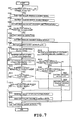
- FIG. 7 is a flowchart conceptually illustrating the sequence of discharge control of the battery pack system according to the second embodiment.
- FIG. 8 is a functional block diagram illustrating an example of a conventional battery pack system.
- FIG. 1 is a functional block diagram illustrating a representative one of a plurality of battery modules 100 - 1 interconnected in series (or in a serial array), in a battery pack system according to a first illustrative embodiment of the present invention.
- the battery pack system includes an electric device (e.g., a power tool) and a battery pack usable as a power source of the electric device.
- the battery module 100 - 1 includes ten (10) Li-ion battery cells 101 each of which has a nominal voltage of 3.6 volts and which are interconnected in series, and the serial array of the ten (10) battery cells 101 (hereinafter, referred to as a “battery cell group”) is electrically connected with a terminal (including a plurality of terminal ends) 107 through an FET (Field-Effect Transistor) 105 for charge and an FET 106 for discharge.
- FET Field-Effect Transistor
- a specific type of the battery cells 101 is, not limited to, Li-ion batteries, but may cover a wide range of types of rechargeable batteries which can generate electric power within the battery pack 200 - 1 .
- a module controller 110 - 1 is electrically connected with a voltage detector 102 for detecting a voltage of each battery cell 101 , a temperature detector 103 for detecting the temperature of the battery cells 101 , and a current detector 104 for detecting a current flowing through the battery cell group, and performs predetermined control (elaborated below by reference to FIG. 3 ) using the FETs 105 and 106 , based on signals received from the detectors 102 , 103 and 104 .
- the module controller 110 - 1 includes a receiver 108 and a transmitter 109 , and, through the receiver 108 and the transmitter 109 , the module controller 110 - 1 receives a signal from and transmits a signal to a load controller 305 disposed in an electric device 300 - 1 depicted in FIG. 2 .
- the battery pack 200 - 1 is constructed by serially interconnecting the three (3) battery modules 100 - 1 , and therefore, the receivers 108 and the transmitters 109 of the battery modules 100 - 1 have respective levels of ground potential which are different between the battery modules 100 - 1 .
- the receivers 108 may be preferably in the form of a device such as a photocoupler (see FIG. 1 ), which can transmit/receive an electrical signal while ensuring electrical isolation.
- a photocoupler see FIG. 1
- the signal communication is of a wired type or a wireless type, as long as the signal communication can allow the discharge control at the module controller 110 - 1 and the discharge control at the load controller 305 , to be performed in association or synchronization with each other, and in addition, it does not matter whether a type of a signal used for the signal communication is analog or digital.
- the terminals used for the signal communication are exclusive, but alternatively, the terminals may be intended also for one or more additional purposes.
- the module controller 110 - 1 is configured to modulate a battery module voltage outputted from the terminal 107 , such that the battery module voltage is a selected one of a plurality of voltages including a first voltage V 1 and a second voltage V 2 which is higher than zero and lower than V 1 (0 ⁇ V 2 ⁇ V 1 ), based on a detection result from at least one of the voltage detector 102 , the temperature detector 103 and the current detector 104 , and/or, based on the signal which the receiver 108 receives from the load controller 305 .
- the first voltage V 1 is one example of the above-described high voltage
- the second voltage V 2 is one example of the above-described low voltage.
- the load controller 305 constitutes one example of the above-described “discharge controller,” and that the module controller 110 - 1 constitutes another example of the “discharge controller.”
- the module controller 110 - 1 when modulating the battery module voltage from V 1 to V 2 , the module controller 110 - 1 transmits from the transmitter 109 to the load controller 305 a signal indicating that the battery module voltage V 1 is permitted to occur. On the other hand, when the battery module voltage V 1 is permitted to occur, the module controller 110 - 1 transmits from the transmitter 109 to the load controller 305 , a signal indicating that V 1 is permitted to occur.
- the battery module voltage V 1 is a voltage required to activate the load controller 305 and the load device 304 of the electric device 300 - 1 , and is approximately equal to the total voltage of the battery cell group within the battery module 110 - 1 .
- the battery module voltage V 2 is lower than V 1 , and may be low enough to keep the load device 304 of the electric device 300 - 1 inactive, or equal to a minimum voltage over which the battery module 100 - 1 can activate the load controller 305 , but at which the battery module 100 - 1 cannot substantially cause the load device 304 to function.
- the battery module voltage V 1 is produced by turning on the FET 106 , so that V 1 can be approximately 36 volts which is equal to the total voltage of the battery cell group of a serial array of battery cells, while the battery module voltage V 2 is produced by performing switching control (i.e., on-off control or duty cycle control) for the FET 106 , so that V 2 can be approximately 5 volts.
- switching control i.e., on-off control or duty cycle control
- a control signal is inputted to the gate of the FET 106 , which has a duty ratio or cycle of, for example, 100%, and, on the other hand, during an output period B in which the battery module voltage V 2 is generated, the control signal has a duty ratio which is lower than that for V 1 , and which is, for example, approximately 10-30%.
- the FET 106 i.e., one example of a switching device connected with a current path
- both the battery module voltages V 1 and V 2 are generated by on-off control or duty cycle control for the FET 106 with respective duty ratios both lower than 100%, so that V 1 and V 2 can be two different voltages which are optimum for the electric device 300 - 1 .
- any one of a variety of different manners may be selected, which include (a) changing the battery module voltage between V 1 and V 2 instantaneously, as illustrated in FIG. 4( a ), (b) changing the battery module voltage in steps, among V 1 , V 2 and at least one intermediate voltage, (c) changing the battery module voltage between V 1 and V 2 substantially gradually and continuously, as illustrated in FIG. 4( b ) (e.g., changing the above-described duty ratio substantially continuously), and the like.
- the module controller 110 - 1 may be configured to turn off the FET 106 , in a case in which, while the battery module voltage V 2 is being generated, the voltage of at least one of the battery cells 101 , which has been detected by the voltage detector 102 , has reduced to a voltage lower than a predetermined value, or in a case in which a predetermined time having a length, for example, equal to or longer than the length of one day, has passed after the output of the battery module voltage V 2 began, to thereby prevent overcharge of the battery cells 101 .
- the FET 106 is controlled by the module controller 110 - 1 , but in an alternative, the FET 106 may be controlled by the load controller 305 , by inputting a signal from the receiver 108 directly to the gate of the FET 106 .
- the FET 106 is disposed within the battery module 100 - 1 , but, in an alternative, the FET 106 may be disposed either in a portion of the battery pack 200 - 1 which is located outside of the battery module 100 - 1 , or in the electric device 300 - 1 .
- FIG. 2 is a functional block diagram illustrating the battery pack system according to the present embodiment.
- Three (3) battery modules 100 - 1 are interconnected in series, via the terminal 107 , to form the battery module group, which is housed within the battery pack 200 - 1 .
- the battery module group is electrically connected with a discharge output terminal 201 via which the battery module group can supply electricity to the electric device 300 - 1 .
- Three (3) receivers 108 of the three (3) battery modules 100 - 1 are interconnected in parallel, and are connected with a transmitter 311 of the electric device 300 - 1 via a receiver 202 of the battery pack 200 - 1 . All of the three (3) battery modules 100 - 1 can simultaneously receive an enable signal or a disable signal, once disable signal a load controller 305 of the electric device 300 - 1 has transmitted the enable signal or the disable signal to the battery pack 200 - 1 through the transmitter 311 .
- three (3) transmitters 109 of the three (3) battery modules 100 - 1 are interconnected in series, and are connected with a receiver 310 of the electric device 300 - 1 through a transmitter 203 of the battery pack 200 - 1 . That is, the load controller 305 of the electric device 300 - 1 can recognize from the status of the receiver 310 , the fact that at least one of the three (3) battery modules 100 - 1 has transmitted the disable signal to the receiver 310 , if any.
- the load controller 305 of the electric device 300 - 1 turns the load device 304 inactive, and transmits the disable signal to the battery pack 200 - 1 .
- the battery module voltages of all of the three (3) battery modules 100 - 1 within the battery pack 200 - 1 become equal to V 2 .
- the electric device 300 - 1 which is connected with the battery pack 200 - 1 , houses the load device 304 and the load controller 305 which controls the load device 304 using electricity supplied from the battery pack 200 - 1 .
- the load device 304 receives electricity from the battery pack 200 - 1 through a power input terminal 301 , via a switch 303 operated by an operator and an FET 302 for load control controlled by the load controller 305 .
- the load controller 305 brings the FET 302 into an electrical conduction state, to thereby electrically connect the battery pack 200 - 1 with the load device 304 .
- the load controller 305 brings the FET 302 into an electrical isolation state, to thereby electrically disconnect the battery pack 200 - 1 from the load device 304 .
- the load controller 305 converts a voltage ( ⁇ V 1 or ⁇ V 2 , as described later) inputted from the battery pack 200 - 1 to a voltage required for keeping the load controller 305 itself active, which is, for example, 5 volts, and receives the resulting voltage.
- the load controller 305 is electrically connected with a voltage detector 306 , a current detector 307 , a switch detector 308 , the receiver 310 and the transmitter 311 . If at least one of conditions is met, which includes, for example, (a) a condition in which a voltage supplied from and through the discharge output terminal 201 of the battery pack 200 - 1 falls outside an allowable range, (b) a condition in which the value of a load current flowing through the load device 304 is larger than a predetermined value, (c) a condition in which the value of the load current has been kept lower than a predetermined value for a predetermined length of time, (d) a condition in which a predetermined time has passed after the switch 303 turned off, (e) a condition in which the load controller 305 cannot control the voltage or the current stably at a target value, and (f) a condition in which the receiver 310 receives a disable signal indicating that at least one of the battery modules 100 - 1 within the battery pack 200 - 1 is
- each battery module 100 - 1 outputs the battery module voltage V 1 .
- a voltage outputted from and through the discharge output terminal 201 of the battery pack 200 - 1 becomes equal to the sum of the battery module voltages V 1 of the battery modules 100 - 1 interconnected in series, which is denoted as ⁇ V 1 .
- the electric device 300 - 1 receives 108 volts from the battery pack 200 - 1 , and operates.
- each battery module 100 - 1 outputs the battery module voltage V 2 .
- a voltage outputted from and through the discharge output terminal 201 of the battery pack 200 - 1 becomes equal to the sum of the battery module voltages V 2 of the battery modules 100 - 1 interconnected in series, which is denoted as ⁇ V 2 .
- the battery module voltage V 2 is 5 volts, then ⁇ V 2 becomes 15 volts.
- the electric device 300 - 1 receives 15 volts from the battery pack 200 - 1 , and the load controller 305 operates using the received voltage of 15 volts. At this time, the voltage is too low to activate the load device 304 , and the load device 304 is inactive.
- the load controller 305 of the electric device 300 - 1 is required to do in an inactive state of the load device 304 is, to enable the switch detector 308 to detect an event that the switch 303 is turned on by the operator, to enable the receiver 310 to detect an event that the battery pack 200 - 1 is permitted to output power, and to be prepared for enabling the electric device 300 - 1 to restart immediately after those two events are detected.
- the load controller 305 while the load device 304 is inactive, requires electrical power for maintaining itself active.
- each of a plurality of battery modules in a serial array is inhibited to output power, while a load device of an electric device is inactive, in order to prevent impression of a high voltage onto every segment within a battery pack.
- the load controller of the electric device cannot receive electricity from the battery pack, and therefore, the electric device is required to include therein an electricity storage device which can store electrical power supplied from the battery pack.
- each battery module 100 - 1 outputs a battery module voltage of V 2
- the battery pack having the battery modules 100 - 1 in a serial array outputs a voltage of ⁇ V 2 .
- this makes it unnecessary to dispose a backup power supply having an electricity storage device which is required for a conventional battery pack.
- the battery module voltage V 2 is preferably selected, so that ⁇ V 2 can fall within a range between an upper voltage and a lower voltage, wherein the upper voltage is 42V at which the electrical-insulation reliability of the battery pack 200 - 1 can be easily ensured, and the lower voltage is a minimum voltage over which the load controller 305 can be kept active even when the load device 304 is inactive.
- each battery module 100 - 1 may have the battery module voltage V 2 which is the same as, or different from that of any one of the other battery modules 100 - 1 .
- V 2 the battery module voltage V 2 which is the same as, or different from that of any one of the other battery modules 100 - 1 .
- the FETs 106 of all of the battery modules 100 - 1 are controlled, for allowing each battery module 100 - 1 to generate the battery module voltage V 2 , at the respective switching duty ratios or cycles which are shared between the FETs 106 , then each battery module 100 - 1 outputs the battery module voltage V 2 having a level depending on the total voltage of the serially-arrayed battery cells in the battery cell group of each battery module 100 - 1 . That is, V 2 varies between the battery modules 100 - 1 , and, each time the battery module voltage of each battery module 100 - 1 alternately changes between V 1 and V 2 , the value of V 2 varies as the remaining charge in the battery cell group decreases.
- step S 101 the load controller 305 of the electric device 300 - 1 waits for the operator to turn on the switch 303 , with the electric device 300 - 1 electrically connected with the battery pack 200 - 1 . If the switch 303 is turned ON, then the process proceeds to step S 102 , and if not so, the waiting mode continues.
- step S 102 the load controller 305 of the electric device 300 - 1 transmits to the battery pack 200 - 1 an enable signal indicating that the load device 304 is permitted to run.
- step S 103 each battery module 100 - 1 of the battery pack 200 - 1 receives the enable signal described above.
- the module controller 110 - 1 detects the voltage and the temperature of at least one of the battery cells 101 of the battery cell group within each battery module 100 - 1 .
- the module controller 110 - 1 determines if the voltage or the temperature of at least one of the battery cells 101 of the battery cell group, falls outside an allowable range pre-selected not to adversely affect the cycle life or the safety of the battery cells 101 , that is, if the voltage or the temperature is in a state that does not permit the discharge. If so, then the module controller 110 - 1 determines that the discharge is inhibited (the branch is “No”). Thereafter, the module controller 110 - 1 performs processing for terminating the control. If not so, then the module controller 110 - 1 determines that the discharge is permitted (the branch is “Yes”). Thereafter, the process proceeds to step S 106 .
- each of ones of the module controllers 110 - 1 which have determined that the discharge is permitted turns on the corresponding FET 106 , with the above-described duty ratio set to, for example, 100%.
- the battery module voltage outputted from the corresponding battery module 100 - 1 is equal to V 1 .
- the current module controller 110 - 1 transmits to the load controller 305 of the electric device 300 - 1 an enable signal indicating that the corresponding battery modules 100 - 1 are permitted to output power. If all of the battery modules 100 - 1 within the battery pack 200 - 1 are permitted to output power, then, at step S 108 , the battery pack 200 - 1 outputs ⁇ V 1 to the electric device 300 - 1 .
- step S 109 the load controller 305 receives the enable signal transmitted from the module controller 100 - 1 at step S 107 , and the process subsequently proceeds to step S 110 .
- step S 110 the load controller 305 determines that it can receive power from the battery pack 200 - 1 , and begins running the load device 304 .
- step S 111 the load controller 305 detects the voltage and the current of the battery pack 200 - 1 , and the position of the switch 303 of the battery pack 200 - 1 . Subsequently, at step S 112 , the load controller 305 determines if the detected voltage or current falls within a predetermined range for allowing the electric device 200 - 1 to be active. If so, then the process proceeds to step S 113 , and if not so, the process proceeds to step S 115 . At step S 113 , the load controller 305 determines whether the switch 303 has been turned off, and, if so, then the process proceeds to step S 115 , and if not so, the process proceeds to step S 114 .
- step S 113 after a predetermined length of time, such as 0.1 seconds at a minimum, or the length of one day at a maximum, has passed since it was determined, in the step S 113 , that the switch 303 was turned off, the process may proceed to step S 115 .
- a predetermined length of time such as 0.1 seconds at a minimum, or the length of one day at a maximum
- the load controller 305 determines if it has received at step S 122 described below, the disable signal transmitted from the module controller 110 - 1 of at least one of the battery modules 100 - 1 of the battery module group. If so, then the process proceeds to step S 115 , and if not so, the process returns to step S 108 to maintain the load device 304 active.
- the load controller 305 stops the load device 304 . Subsequently, at step S 116 , the load controller 305 transmits to the module controllers 110 - 1 of all of the battery modules 100 - 1 , a disable signal indicating that power supply to the load device 304 is inhibited. The disable signal is processed at step S 120 described below.
- each of the module controllers 110 - 1 of all of the battery modules 100 - 1 detects the voltage, the temperature and the current, of at least one of the battery cells 101 of the battery cell group housed within a corresponding one of the battery modules 100 - 1 .
- each module controller 110 - 1 determines if the voltage, the temperature or the current, of at least one of the battery cells 101 of the battery cell group, falls outside a range pre-selected not to adversely affect the cycle life or the safety of the battery cells 101 , that is, if the voltage, the temperature or the current is in a state that does not permit the discharge. If so (the branch is “No”), then the process proceeds to step S 121 , and if not so (the branch is “Yes”), the process proceeds to step S 120 .
- the corresponding module controller 110 - 1 determines if it has received from the load controller 305 , a disable signal indicating that power supply to the load device 304 is inhibited. If so, then the process proceeds to step S 121 , and if not so, then the process returns to step S 108 to keep the load device 304 running.
- step S 116 the load controller 305 transmits the disable signals, then all of the battery modules 100 - 1 , after simultaneous reception of the disable signals, each implement step S 121 .
- each module controller 110 - 1 shifts the operation state of the FET 106 from a continuous ON state in which the FET 106 is held in an ON state, to a switching state in which the FET 106 alternately experiences an ON state and an OFF state. That is, the battery module voltage of the battery module 100 - 1 is modulated from V 1 to V 2 .
- the load controller 305 may execute step S 111 and step S 112 in the description order, and, upon detection of a drop of the output voltage of the battery pack 200 - 1 constructed with a group of a serially-interconnected battery modules to below a predetermined value (e.g., an operational voltage at startup), the load controller 305 may perform processing for stopping the load device 304 .
- a predetermined value e.g., an operational voltage at startup
- each module controller 110 - 1 transmit to the load controller 305 of the electric device 300 - 1 a disable signal indicating that power output of the battery modules 100 - 1 is inhibited, and the process proceeds to step S 117 .
- the disable signal is processed at step S 114 .
- step S 117 because the previous execution of step S 121 results in modulation of the battery module voltage of each battery module 100 - 1 from V 1 to V 2 , the output voltage of the battery pack 200 - 1 is modulated from ⁇ V 1 to ⁇ V 2 .
- the load device 304 Because of reception of a voltage of ⁇ V 2 from the battery pack 200 - 1 , the load device 304 becomes inactive, while the load controller 305 is kept active, and, as the processes in step S 101 -S 110 show, the load controller 305 waits until it detects a condition in which there is the need for restarting the load device 304 .
- the FET 106 constitutes an example of the “switching device” set forth in the above mode (2), and a portion of each module controller 110 - 2 which implements step S 106 and step S 121 in FIG. 3 , constitutes an example of the “switching-control circuitry” set forth in the same mode.
- step S 108 the battery module voltage of each battery module 100 - 1 is equal to V 1
- the resulting output voltage of the battery pack 200 - 1 is equal to ⁇ V 1
- step S 117 the battery module voltage of each battery module 100 - 1 is equal to V 2 lower than V 1
- the resulting output voltage of the battery pack 200 - 1 is equal to ⁇ V 2 far lower than ⁇ V 1 .
- the battery pack 200 - 1 supplies electricity featured by ⁇ V 1 or ⁇ V 2 to the load controller 305 .
- This configuration minimizes how often a maximum voltage impressed onto inter segments within the battery pack system becomes equal to ⁇ V 1 , and, on the other hand, while the electric device 300 - 1 is not used, this configuration reduces the maximum voltage impressed onto the inner segments within the battery pack system, to ⁇ V 2 . Therefore, this configuration can keep the load controller 305 active, without using a backup power supply having an electricity storage device, while improving the electrical-insulation reliability (e.g., an ability of protecting a human body from suffering electric shock despite of intrusion of rainwater into the battery pack 200 - 1 ), and this configuration further provides an additional effect of ensuring the load controller 305 to successfully restart even after a long-term inactive stop phase of the electric device 300 - 1 , in addition to a cost reduction effect.
- the electric device 300 - 1 if the electric device 300 - 1 turns inactive due to the circumstance on the side of the electric device 300 - 1 , then all of the battery modules 100 - 1 simultaneously receive disable signals from the electric device 300 - 1 , resulting in a simultaneous reduction of the output voltages of all of the battery modules 100 - 1 from V 1 to V 2 .
- the output voltage of the at least one battery module 100 - 1 is reduced from V 1 to V 2 , while the output voltages of the remaining battery modules 100 - 1 each experience a transition phase in which each output voltage is kept constant.
- each battery module 100 - 1 if has experienced a voltage drop, transmits the disable signal to the electric device 300 - 1 , and as a result, the electric device 300 - 1 , in turn, irrespective of its own status, transmits the disable signals to all of the battery modules 100 - 1 . Consequently, for all of the battery modules 100 - 1 , each output voltage eventually reduces from V 1 to V 2 . Therefore, the present embodiment would prevent any one of the battery modules 100 - 1 from continuously outputting V 1 after the concurrent output-voltage reduction, to thereby lose the electrical-insulation reliability.
- FIG. 5 is a functional block diagram illustrating a representative one of serially-arrayed battery modules 100 - 2 in a battery pack 200 - 2 (see FIG. 6 ) of the battery pack system according to the present embodiment.
- the battery module 100 - 2 is similar in the underlying configuration with the battery module 100 - 1 of the battery pack system according to the first embodiment, except for a second output section 111 which is added to the same as the battery module 100 - 1 according to the first embodiment.
- the second output section 111 is constructed with resistances 112 , 113 and a diode 114 .
- the second output section 111 may be preferably connected with the circuit of the battery module 100 - 2 , so that a voltage of the battery cell group of the battery cells 101 can be inputted into the second output section 111 from between the battery cell group and the FET 106 .
- a module controller 110 - 2 of the battery module 100 - 2 modulates the battery module voltage outputted from the terminal 107 of a battery pack 200 - 2 to a selected one of V 1 and V 2 , based on a detection result from at least one of the voltage detector 102 , the temperature detector 103 and the current detector 104 , and/or, based on a signal received by the receiver 108 from a main controller 209 (see FIG. 6 ).
- the battery module voltage V 1 is generated, after turning on the FET 106 , by outputting the total voltage of the battery cell group through the terminal 107 .
- the battery module voltage V 2 is generated, after turning off the FET 106 , by dividing the total voltage of the battery cell group using the resistances 112 and 113 , to produce a fractional voltage of the total voltage, and by outputting the fractional voltage from the terminal 107 through the diode 114 .
- the resistances 112 , 113 and the diode 114 together constitute an example of the “voltage divider” set forth in the above mode (3).
- the battery module voltage is made equal to V 2 , and if not so, the battery module voltage is made equal to V 1 .
- the module controller 110 - 2 when modulating the battery module voltage from V 1 to V 2 , transmits from the transmitter 109 a disable signal indicating that the battery module 100 - 2 is not permitted to output the battery module voltage V 1 . On the other hand, if the battery module voltage V 1 is permitted to occur, then the module controller 110 - 2 transmits an enable signal indicating the permission from the transmitter 109 .
- the battery module voltage V 1 is a voltage required to operate the inverter circuit 204 and the main controller 209 , which is approximately equal to the total voltage of the battery cell group in which the battery cells are interconnected in series within the battery module 100 - 2 .
- values of the resistances 112 and 113 are preferably selected such that the battery module voltage V 2 is lower than V 1 , and is equal to a minimum voltage over which the main controller 209 can be active, and at which the inverter circuit 204 cannot be active, or can be active but cannot output power large enough to allow the electric device to operate and substantially achieve its intended purpose.
- the battery module voltage V 1 is produced by turning on the FET 106 , so that V 1 can be approximately 36 volts which is equal to the total voltage of the battery cell group, while the battery module voltage V 2 is produced by turning off the FET 106 and by dividing the total voltage of the battery cell group to produce a fractional voltage, so that V 2 can be approximately 5 volts.
- both of the battery module voltages V 1 and V 2 may be preferably produced by duty cycle control for the FET 106 , so that V 1 and V 2 can be two different voltages which are optimum for the battery pack system.
- any one of a variety of different manners may be preferably selected, which include (a) changing the battery module voltage between V 1 and V 2 instantaneously, (b) changing the battery module voltage in steps, among V 1 , V 2 and at least one intermediate voltage, (c) changing the battery module voltage between V 1 and V 2 substantially gradually and continuously, and the like.
- gradually changing the battery module voltage from V 1 to V 2 and/or from V 2 to V 1 would provide an additional effect of suppressing surge voltage caused by the reactance of the relevant circuit, to thereby reduce burden on components in the circuit.
- the module controller 110 - 2 may be configured to further include therein a device for blocking a current to be consumed by the second output section 111 , in a case in which, while the battery module voltage V 2 is being generated, the voltage of at least one of the battery cells 101 , which has been detected by the voltage detector 102 , has reduced to a voltage lower than a predetermined value, or in a case in which a predetermined time having a length, for example, equal to or longer than the length of one day, has passed after the output of the battery module voltage V 2 began, to thereby prevent overcharge of the battery cells 101 .
- the FET 106 is controlled by the module controller 110 - 2 , but in an alternative, the FET 106 may be controlled by the main controller 209 , by inputting a signal from the receiver 108 directly to the gate of the FET 106 .
- the FET 106 and the second output section 111 are disposed within the battery module 100 - 2 , but, in an alternative, the FET 106 and the second output section 111 may be disposed either in a portion of the battery pack 200 - 2 which is located outside the battery module 100 - 2 .
- FIG. 6 is a function block diagram illustrating the battery pack system according to the present embodiment.
- five (5) battery modules 100 - 2 are serially interconnected via the terminals 107 of the battery modules 100 - 2 , forming a battery module group, which is housed within the battery pack 200 - 2 .
- the battery module group is electrically connected with an inverter circuit 204 .
- the inverter circuit 204 converts an output voltage of the battery module group into an output voltage having a level which is comparable to that of the commercial power source, which enables power supply to an electric device (not shown) which is electrically connected with an output terminal 206 .
- the main controller 209 converts a voltage inputted from the battery module group ( ⁇ V 1 or ⁇ V 2 ) into a voltage, for example, 5 volts, which is required to continuously keep the main controller 209 providing its own function in order for the main controller 209 to receive the resulting voltage.
- the battery pack 200 - 2 includes therein a charging circuit 208 configured to receive a voltage of the commercial power source from an input terminal 207 , and convert the voltage into a DC voltage, which allows the battery cells of the battery module 100 - 2 to be charged.
- a charging circuit 208 configured to receive a voltage of the commercial power source from an input terminal 207 , and convert the voltage into a DC voltage, which allows the battery cells of the battery module 100 - 2 to be charged.
- the battery pack 200 - 2 further includes therein a switch 205 which operates such that, if the voltage of the commercial power source is supplied into the input terminal 207 , then the switch 205 connects an A side to the output terminal 206 , which allows the voltage of the commercial power source to be directly supplied to the electric device which is electrically connected with the output terminal 206 , but, if the voltage of the commercial power source is not supplied to the input terminal 207 , then the switch 205 connects a B side to the output terminal 206 , which allows the voltage outputted from the inverter circuit 204 , to be supplied to the electric device which is electrically connected with the output terminal 206 .
- the main controller 209 Five (5) receivers 108 of the five (5) battery modules 100 - 2 are electrically connected with the main controller 209 via respective receivers 202 and respective transmitters 203 . It is added that the receivers 202 and the transmitters 203 can use any one of possible wirings, as long as it allows bi-directional communication between the main controller 209 and the module controllers 110 - 2 of the battery modules 100 - 2 . This allows the main controller 209 to send an instruction to the each battery module 100 - 2 , and also allows each battery module 100 - 2 to send an instruction to the main controller 209 , wherein the instruction is for modulation of the battery module voltage from V 2 to V 1 , or from V 1 to V 2 .
- the main controller 209 constitutes an example of the above-described “discharge controller” (i.e., a type of a discharge controller in common to the battery modules 100 - 2 ), while the module controller 110 - 2 within each battery module 100 - 2 constitutes another example of the “discharge controller” (i.e., a type of a discharge controller disposed on a per-battery-module basis).
- the output-terminal insertion indicator 210 includes therein a switch 211 for mechanically detecting a connecting action of a terminal of the electric device to the output terminal 206 , and for converting the detection result into an electric signal.
- the output-terminal insertion detector 210 detects the connecting action is not limited to the above-mentioned method, but it may alternatively employ a method of electrically detecting the connecting action, or a method of movement of a terminal cover (not shown) which is disposed at the output terminal 206 so that it moves between an open position and a closed position relative to the output terminal 206 , to thereby indirectly detect the connecting action.
- the main controller 209 operates such that, if at least one of conditions is met, which includes, for example, (a) a condition in which the terminal of the electric device has not been connected with the output terminal 206 , (b) a condition in which a predetermined length of time has passed since the inverter circuit 204 entered a non-load state, (c) a condition in which the inverter circuit 204 cannot control the voltage or the current stably at a target value, and (d) a condition in which the receiver 202 receives a disable signal indicating that at least one of the battery modules 100 - 2 within the battery pack 200 - 2 is not permitted to output power, then the main controller 209 , after stopping the inverter circuit 204 to perform output control, transmits from the transmitter 203 to the five (5) battery modules 100 - 2 a disable signal indicating that the inverter circuit 204 is not permitted to operate.
- each battery module 100 - 2 outputs the battery module voltage V 1 .
- a voltage inputted into the inverter circuit 204 becomes equal to the sum of the battery module voltages V 1 of the battery modules 100 - 2 interconnected in series, which is denoted as ⁇ V 1 .
- the inverter circuit 204 receives a direct current voltage of 180 volts from the battery module group, converts it into an alternate current voltage of 100 volts, and outputs it.
- each battery module 100 - 2 outputs the battery module voltage V 2 .
- a voltage inputted into the inverter circuit 204 becomes equal to the sum of the battery module voltages V 2 of the five battery modules 100 - 2 interconnected in series, which is denoted as ⁇ V 2 .
- ⁇ V 2 the battery module voltage V 2 is 5 volts, then ⁇ V 2 becomes 25 volts.
- the main controller 209 receives 25 volts from the battery module group, and the main controller 209 operates using the received voltage of 25 volts. At this time, the voltage is too low to be converted into an alternate current voltage of 100 volts, the inverter circuit 204 is inactive.
- What the main controller 209 is required to do in an inactive state of the inverter circuit 204 is, to enable the output-terminal insertion detector 210 to detect a first event that the terminal of the electric device is connected to the output terminal 206 , to enable the receiver 202 to detect a second event that all of the five (5) battery modules 100 - 2 are permitted to output power, and to be prepared for enabling the inverter circuit 204 to restart in response to concurrent detection of the first and second events.
- What the main controller 209 is further required is to activate the state-of-charge indicator 212 , if needed. As a result, the main controller 209 , while the inverter circuit 204 is inactive, requires electrical power for maintaining itself active.
- each of a plurality of battery modules in a serial array is inhibited to output power, while a discharge controller of a battery pack is inactive, in order to prevent impression of a high voltage onto every segment within the battery pack.
- the discharge controller cannot receive electricity from a group of the battery modules, and therefore, the battery pack is required to include therein an electricity storage device which can store electrical power supplied from the battery module group.
- each battery module 100 - 2 outputs a battery module voltage of V 2
- a group of the battery modules 100 - 2 in a serial array outputs a voltage of ⁇ V 2 .
- this makes it unnecessary to dispose a backup power supply having an electricity storage device which is required for a conventional battery pack.
- a current flowing through the diode 114 of each battery module 100 - 2 is equal to that of the diode 114 of any other battery module 100 - 2 , and is approximately equal to a current consumed by the main controller 209 .
- a current flowing through the resistance 113 of each battery module 100 - 2 depends on the voltage of the battery cell group within each battery module 100 - 2 . If the voltage of the battery cell group within one of the battery modules 100 - 2 is higher than that of the battery cell group within any other battery module 100 - 2 , then the current flowing through the resistance 113 of the one battery module 100 - 2 is larger than a current flowing through the resistance 113 of any other battery module 100 - 2 .
- a voltage difference between the battery cell groups of the battery modules 110 - 2 becomes larger, as the battery modules 100 - 2 is used longer, due to the differences in the various properties between the battery cells 101 - 2 .
- the present embodiment would provide of an additional effect of autonomously eliminating the above-described voltage difference, that is, a capacity imbalance between the battery modules 100 - 2 , with improved system reliability of the battery pack system.
- the battery module voltage V 2 is preferably selected, so that ⁇ V 2 can fall within a range between an upper voltage and a lower voltage, wherein the upper voltage is 42V at which the electrical-insulation reliability of the battery pack 200 - 2 can be easily ensured, and the lower voltage is a minimum voltage over which the main controller 209 can be kept active even when the inverter circuit 204 is inactive.
- each battery module 100 - 2 may have the battery module voltage V 2 which depends on the voltage of the battery cell group of each battery module 100 - 2 , V 2 varies between the battery modules 100 - 2 , and, each time the battery module voltage of each battery module 100 - 2 alternately changes between V 1 and V 2 , the value of V 2 varies as the remaining charge in the battery cell group decreases.
- FIG. 7 is a flowchart conceptually illustrating the sequence of the discharge control of the battery pack system according to the present embodiment.
- the main controller 209 waits for the output-terminal insertion detector 210 to detect a plug-in event that the terminal of the electric device is plugged in the output terminal 206 of the battery pack 200 - 2 . If the plug-in event is detected, then the process proceeds to step S 202 , and if not so, the main controller 209 further waits.
- the main controller 209 transmits to each battery module 100 - 2 an enable signal indicating that the inverter circuit 204 is permitted to run. Thereafter, at step S 203 , each battery module 100 - 2 receives the enable signal.
- the module controller 110 - 2 of each battery module 100 - 2 detects the voltage and the temperature of at least one of the battery cells 101 of the battery cell group within each battery module 100 - 2 . Thereafter, at step S 205 , on a per-battery-module basis, the module controller 110 - 2 determines if the voltage or the temperature of at least one of the battery cells 101 of the battery cell group, falls outside an allowable range pre-selected not to adversely affect the cycle life or the safety of the battery cells 101 , that is, if the voltage or the temperature is in a state that does not permit the discharge. If so, then the module controller 110 - 2 determines that the discharge is inhibited (the branch is “No”). Thereafter, the module controller 110 - 2 performs processing for terminating the control. If not so, then the module controller 110 - 2 determines that the discharge is permitted (the branch is “Yes”). Thereafter, the process proceeds to step S 206 .
- each of ones of the module controllers 110 - 2 which have determined that the discharge is permitted, turns on the corresponding FET 106 .
- the battery module voltage outputted from the corresponding battery module 100 - 2 is equal to V 1 .
- the current module controller 110 - 2 transmits to the main controller 209 an enable signal indicating that the corresponding battery modules 100 - 2 are permitted to output power. If all of the battery modules 100 - 2 within the battery pack 200 - 2 are permitted to output power, then, at step S 208 , the battery module group of the battery packs 200 - 2 outputs ⁇ V 1 to the inverter circuit 204 .
- step S 209 the main controller 209 receives the enable signal transmitted from the module controller 100 - 2 at step S 207 , and the process subsequently proceeds to step S 210 .
- step S 210 the main controller 209 determines that the battery module group can output power to the inverter circuit 204 , and begins running the inverter circuit 204 . It is added that, for the inverter circuit 204 to run, it is necessary for all the battery modules 100 - 2 transmit the enable signal.
- step S 211 the main controller 209 detects the voltage and the current of the battery module group, and an event that the terminal of the electric device has been plugged in the output terminal 206 . Subsequently, at step S 212 , the main controller 209 determines if the detected voltage or current falls within a predetermined range for allowing the inverter circuit 204 to become active. If so, then the process proceeds to step S 213 , and if not so, the process proceeds to step S 215 .
- step S 213 the main controller 209 determines whether the terminal of the electric device has been removed from the output terminal 206 , and, if so, then the process proceeds to step S 215 , and if not so, the process proceeds to step S 214 .
- step S 213 After a predetermined length of time, such as 0.1 seconds at a minimum, or the length of one day at a maximum, has passed since it was determined, in the step S 213 , that the terminal of the electric device was removed from the output terminal 206 , the process may proceed to step S 215 .
- a predetermined length of time such as 0.1 seconds at a minimum, or the length of one day at a maximum
- step S 214 the main controller 209 determines if it has received at step S 222 described below, the disable signal transmitted from the module controller 110 - 2 of at least one of the battery modules 100 - 2 of the battery module group. If so, then the process proceeds to step S 215 , and if not so, the process returns to step S 208 to maintain the inverter circuit 204 active.
- the main controller 209 stops the inverter circuit 204 . Subsequently, at step S 216 , the main controller 209 transmits to the module controllers 110 - 2 of all of the battery modules 100 - 2 , a disable signal indicating that power supply to the inverter circuit 204 is inhibited. The disable signal is processed at step S 220 described below.
- step S 208 Upon completion of the above-described step S 208 , the process proceeds to step S 218 , and also to step S 209 for parallel execution.
- step S 218 each of the module controllers 110 - 2 of all of the battery modules 100 - 2 detects the voltage, the temperature or the current, of at least one of the battery cells 101 of the battery cell group housed within a corresponding one of the battery modules 100 - 2 .
- each module controller 110 - 2 determines if the voltage, the temperature or the current, of at least one of the battery cells 101 of the battery cell group, falls outside a range pre-selected not to adversely affect the cycle life or the safety of the battery cells 101 , that is, if the voltage, the temperature or the current is in a state that does not permit the discharge. If so (the branch is “No”), then the process proceeds to step S 221 , and if not so (the branch is “Yes”), the process proceeds to step S 220 .
- the corresponding module controller 110 - 2 determines if it has received from the main controller 209 , a disable signal indicating that power supply to the inverter circuit 204 is inhibited. If so, then the process proceeds to step S 221 , and if not so, then the process returns to step S 208 to keep the inverter circuit 204 running. It is added that, if, at step S 216 , the main controller 209 transmits the disable signals, then all of the battery modules 100 - 2 , after simultaneous reception of the disable signals, each implement step S 221 .
- each module controller 110 - 2 shifts the operation state of the FET 106 from an ON state to an OFF state, thereby modulate the battery module voltage of the battery module 100 - 2 from V 1 to V 2 which is produced as a result of the voltage division using the resistances 112 and 113 .
- the main controller 209 may execute step S 211 and step S 212 in the description order, and, upon detection of a drop of the output voltage of the battery module group to below a predetermined value, the main controller 209 may perform processing for stopping the inverter circuit 204 .
- each module controller 110 - 2 transmit to the main controller 209 a disable signal indicating that power output of the battery modules 100 - 2 is inhibited, and the process proceeds to step S 217 .
- the disable signal is processed at step S 214 .
- step S 217 because the previous execution of step S 221 results in modulation of the battery module voltage of each battery module 100 - 2 from V 1 to V 2 , the output voltage of the battery pack 200 - 2 is modulated from ⁇ V 1 to ⁇ V 2 . Because of reception of a voltage of ⁇ V 2 from the battery module group, the inverter circuit 204 becomes inactive, while the main controller 209 is kept active, and, as the processes in step S 201 -S 210 show, the main controller 209 waits until it detects a condition in which there is the need for restarting the inverter circuit 204 .
- the FET 106 constitutes an example of the “switching device” set forth in the above mode (3)
- the resistances 112 and 113 and the diode 114 together constitute an example of the “voltage divider” set forth in the same mode
- these components, and a portion of each module controller 110 - 2 which implements step S 206 and step S 221 in FIG. 7 together constitute an example of the “output voltage modulator” set forth in the same mode.
- step S 208 the battery module voltage of each battery module 100 - 2 is equal to V 1
- the resulting output voltage of the battery pack 200 - 2 is equal to ⁇ V 1
- step S 217 the battery module voltage of each battery module 100 - 2 is equal to V 2 lower than V 1
- the resulting output voltage of the battery pack 200 - 2 is equal to ⁇ V 2 far lower than ⁇ V 1 .
- the battery module group supplies electricity featured by ⁇ V 1 or ⁇ V 2 to the main controller 209 .
- This configuration minimizes how often a maximum voltage impressed onto inter segments within the battery pack system becomes equal to ⁇ V 1 , and, on the other hand, while the electric device is not connected with the output terminal 206 , or while the electric device is not used, this configuration reduces the maximum voltage impressed onto the inner segments within the battery pack system, to ⁇ V 2 .
- this configuration can keep the main controller 209 active, without using a backup power supply having an electricity storage device, while improving the electrical-insulation reliability (e.g., an ability of protecting a human body from suffering electric shock despite of intrusion of rainwater into the battery pack 200 - 2 ), and this configuration further provides an additional effect of ensuring the inverter circuit 204 to successfully restart even after a long-term inactive stop phase of he electric device 3 , in addition to a cost reduction effect.
- the electrical-insulation reliability e.g., an ability of protecting a human body from suffering electric shock despite of intrusion of rainwater into the battery pack 200 - 2
- this configuration further provides an additional effect of ensuring the inverter circuit 204 to successfully restart even after a long-term inactive stop phase of he electric device 3 , in addition to a cost reduction effect.
Landscapes
- Engineering & Computer Science (AREA)
- Manufacturing & Machinery (AREA)
- Chemical & Material Sciences (AREA)
- Chemical Kinetics & Catalysis (AREA)
- Electrochemistry (AREA)
- General Chemical & Material Sciences (AREA)
- Power Engineering (AREA)
- Charge And Discharge Circuits For Batteries Or The Like (AREA)
- Secondary Cells (AREA)
- Battery Mounting, Suspending (AREA)
Applications Claiming Priority (3)
| Application Number | Priority Date | Filing Date | Title |
|---|---|---|---|
| JP2010-092789 | 2010-04-14 | ||
| JP2010092789A JP4602471B1 (ja) | 2010-04-14 | 2010-04-14 | 電池パックおよび電池パックシステム |
| JP2010163549A JP5475581B2 (ja) | 2010-04-14 | 2010-07-21 | 電池パックおよび電池パックシステム |
Publications (2)
| Publication Number | Publication Date |
|---|---|
| US20110254508A1 US20110254508A1 (en) | 2011-10-20 |
| US8638065B2 true US8638065B2 (en) | 2014-01-28 |
Family
ID=61617278
Family Applications (1)
| Application Number | Title | Priority Date | Filing Date |
|---|---|---|---|
| US13/084,227 Expired - Fee Related US8638065B2 (en) | 2010-04-14 | 2011-04-11 | Battery pack and battery pack system |
Country Status (3)
| Country | Link |
|---|---|
| US (1) | US8638065B2 (ko) |
| EP (1) | EP2378603B1 (ko) |
| JP (2) | JP4602471B1 (ko) |
Cited By (4)
| Publication number | Priority date | Publication date | Assignee | Title |
|---|---|---|---|---|
| US20140025323A1 (en) * | 2012-07-17 | 2014-01-23 | Po Yin CHAO | Cell voltage monitoring and self-calibrating device |
| US20150214755A1 (en) * | 2014-01-27 | 2015-07-30 | Fairchild Semiconductor Corporation | Control and current measurement function for battery charging, protection and fuel gauge coulomb counting |
| US20160172871A1 (en) * | 2011-10-14 | 2016-06-16 | Lg Innotek Co., Ltd. | Wireless power transmitter |
| US10742054B2 (en) | 2014-09-30 | 2020-08-11 | International Business Machines Corporation | Intelligent composable multi-function battery pack |
Families Citing this family (19)
| Publication number | Priority date | Publication date | Assignee | Title |
|---|---|---|---|---|
| JP4104648B1 (ja) * | 2007-09-13 | 2008-06-18 | 和征 榊原 | 電池パック |
| JP4216898B1 (ja) * | 2008-03-28 | 2009-01-28 | 和征 榊原 | 電池パック |
| US8766596B2 (en) * | 2011-09-06 | 2014-07-01 | Energy Pass Incorporation | Battery management system and battery management method |
| WO2013042474A1 (ja) * | 2011-09-21 | 2013-03-28 | 日本電気株式会社 | 電池制御システム、電池制御装置、電池制御方法、および記録媒体 |
| JP5971680B2 (ja) * | 2012-01-11 | 2016-08-17 | 株式会社東芝 | 電池寿命事前検知方法、電池システム、及び電池コントローラ |
| WO2013145913A1 (ja) * | 2012-03-26 | 2013-10-03 | ソニー株式会社 | 正極活物質、正極、二次電池、電池パック、電動車両、電力貯蔵システム、電動工具および電子機器 |
| RU2561826C2 (ru) * | 2012-06-29 | 2015-09-10 | Общество с ограниченной ответственностью "Системы управления хранением энергии" (ООО "СУХЭ") | Батарея электрических накопителей энергии с распределенной аналитической системой управления |
| JP6207127B2 (ja) * | 2012-07-12 | 2017-10-04 | 株式会社マキタ | 測定システム |
| US9300326B2 (en) * | 2012-11-01 | 2016-03-29 | Qualcomm Incorporated | Prevention of output supply boosting upon removal of input adapter |
| JP6193573B2 (ja) * | 2013-01-10 | 2017-09-06 | ラピスセミコンダクタ株式会社 | 電池監視システム、電池監視装置、及び電池監視システムの起動方法 |
| US8970134B2 (en) * | 2013-03-11 | 2015-03-03 | Osram Sylvania Inc. | Systems and methods of preventing strobing light output |
| US9236749B2 (en) * | 2013-04-08 | 2016-01-12 | GM Global Technology Operations LLC | Vehicle battery system balancing systems and methods |
| JP6378003B2 (ja) * | 2014-08-27 | 2018-08-22 | ラピスセミコンダクタ株式会社 | 半導体装置、電池監視システム、及び半導体装置の起動方法 |
| KR102246632B1 (ko) * | 2017-07-11 | 2021-04-30 | 주식회사 엘지화학 | 리튬 금속을 음극으로 하는 이차전지의 제조방법 |
| DE102017124153B4 (de) * | 2017-10-17 | 2019-07-18 | Einhell Germany Ag | Verfahren und System zum Betreiben von mehreren in einem Elektrogerät eingesetzten Akkupacks |
| RU182710U1 (ru) * | 2018-01-30 | 2018-08-29 | Сергей Александрович Иванов | Батарейный аккумуляторный модуль |
| US11228190B2 (en) | 2018-12-04 | 2022-01-18 | Cohelios, Llc | Mobile power system with bidirectional AC-DC converter and related platforms and methods |
| CN110967649B (zh) * | 2019-12-09 | 2022-06-03 | 南京瑞控电气有限公司 | 一种在线式电池组单体加载巡检系统及方法 |
| DE102020209397A1 (de) * | 2020-07-24 | 2022-01-27 | Robert Bosch Gesellschaft mit beschränkter Haftung | Verfahren zur Erfassung von elektrischen Fehlerzuständen eines Wechselakkupacks sowie System zur Durchführung des Verfahrens |
Citations (46)
| Publication number | Priority date | Publication date | Assignee | Title |
|---|---|---|---|---|
| JPH02162662A (ja) | 1988-12-15 | 1990-06-22 | Sanyo Electric Co Ltd | 充電器 |
| JPH09154236A (ja) | 1995-11-28 | 1997-06-10 | Isuzu Motors Ltd | 電気自動車用電源装置 |
| US5721481A (en) | 1995-03-08 | 1998-02-24 | International Business Machines Corp. | Battery charger for an electronic device and a spare battery |
| JP2000312443A (ja) | 1999-04-27 | 2000-11-07 | Shin Kobe Electric Mach Co Ltd | モジュール電池制御装置、モジュール電池ユニット及びモジュール電池制御方法 |
| JP2001023589A (ja) | 1999-07-13 | 2001-01-26 | Hitachi Ltd | バッテリパック |
| JP2001116776A (ja) | 1999-10-19 | 2001-04-27 | Honda Motor Co Ltd | 電池電圧測定装置 |
| JP2001231178A (ja) | 2000-02-15 | 2001-08-24 | Shin Kobe Electric Mach Co Ltd | 組電池制御装置、モジュール電池ユニット、モジュール電池及び組電池制御方法 |
| JP2001333547A (ja) | 2000-05-22 | 2001-11-30 | Japan Storage Battery Co Ltd | 無停電電源装置 |
| JP2002010517A (ja) | 2000-06-27 | 2002-01-11 | Toshitaka Takei | インバーター装置システム |
| JP2002254355A (ja) | 2001-03-02 | 2002-09-10 | Hitachi Koki Co Ltd | コードレス工具 |
| US6486635B1 (en) | 2000-03-02 | 2002-11-26 | Fujitsu Limited | Monitor signal output circuit, battery pack, battery voltage monitor circuit, battery system, apparatus, battery voltage monitor method, and battery voltage monitor program storage medium |
| JP2004048964A (ja) | 2002-07-15 | 2004-02-12 | Toshiba Corp | 無停電電源装置及び無瞬断系統切換装置 |
| JP2004064977A (ja) | 2002-07-31 | 2004-02-26 | Densei Lambda Kk | 無停電電源装置 |
| US20040066172A1 (en) | 2001-05-25 | 2004-04-08 | Hitachi Koki Co., Ltd. | DC power source unit with battery charging function |
| JP2004112954A (ja) | 2002-09-20 | 2004-04-08 | Hitachi Home & Life Solutions Inc | 蓄電装置 |
| JP2004147022A (ja) | 2002-10-23 | 2004-05-20 | Sony Corp | 電源装置及びテレビジョン受像機 |
| JP2005117780A (ja) | 2003-10-07 | 2005-04-28 | Matsushita Electric Ind Co Ltd | 電池用保護icおよびそれを利用した電池パック |
| US20050194931A1 (en) | 2004-03-05 | 2005-09-08 | Denso Corporation | Circuit system for a battery electronic control unit |
| US20060012337A1 (en) | 2004-07-14 | 2006-01-19 | Renesas Technology Corp. | Battery-voltage monitoring integrated-circuit and battery-voltage monitoring system |
| US20060012342A1 (en) * | 2002-07-17 | 2006-01-19 | Mathews Associates, Inc. | Self-heating battery that automatically adjusts its heat setting |
| JP2006067782A (ja) | 2004-08-27 | 2006-03-09 | Taida Electronic Ind Co Ltd | ステーター構造 |
| JP2006109540A (ja) | 2004-09-30 | 2006-04-20 | Sony Corp | バッテリーパック |
| US20060103350A1 (en) * | 2004-11-12 | 2006-05-18 | Akku Power Electronic Co., Ltd. | [an equalizing-charge charger] |
| US20070024237A1 (en) | 2003-10-14 | 2007-02-01 | Credo Technology Corporation And Robert Bosch Gmbh | Battery charging jobsite lunchbox |
| JP2007110820A (ja) | 2005-10-12 | 2007-04-26 | Sanyo Electric Co Ltd | パック電池 |
| US20070108942A1 (en) | 2002-11-22 | 2007-05-17 | Johnson Todd W | Method and system for protection of a lithium-based multicell battery pack including a heat sink |
| US20070188130A1 (en) | 2006-02-09 | 2007-08-16 | Scheucher Karl F | Scalable intelligent power supply system and method |
| JP2007229827A (ja) | 2006-02-28 | 2007-09-13 | Hitachi Koki Co Ltd | コードレス電動工具及びこれに用いられるバッテリ装置 |
| JP4104648B1 (ja) | 2007-09-13 | 2008-06-18 | 和征 榊原 | 電池パック |
| US20080224661A1 (en) | 2006-11-20 | 2008-09-18 | Onose Katsuya | Charging device for portable electronic device battery and portable phone battery |
| US20080224667A1 (en) | 2007-03-14 | 2008-09-18 | Koji Tanaka | Method for charging battery pack |
| US20080238370A1 (en) | 2005-10-28 | 2008-10-02 | Carrier David A | Battery pack for cordless power tools |
| JP4216898B1 (ja) | 2008-03-28 | 2009-01-28 | 和征 榊原 | 電池パック |
| US7511451B2 (en) | 2005-07-07 | 2009-03-31 | Gerald Pierce | Electrical energy source |
| US20090102421A1 (en) | 2007-10-23 | 2009-04-23 | Iks Co., Ltd. | Apparatus and method for charging and discharging serially-connected batteries |
| US20090108806A1 (en) | 2006-09-19 | 2009-04-30 | Nobuhiro Takano | Adaptor, assembly of battery pack and adaptor, and electric tool with the same |
| US20090146824A1 (en) * | 2004-10-28 | 2009-06-11 | Astrium Sas | Methods for Controlling a Rechargeable Battery and Rechargeable Battery for Carrying Out Said Method |
| US7567116B2 (en) | 2006-10-06 | 2009-07-28 | Texas Instruments Incorporated | Voltage converting circuit and battery device |
| US20090208821A1 (en) | 2005-07-07 | 2009-08-20 | Kabushi Kaisha Toshiba | Battery system |
| US20090212738A1 (en) | 2008-02-25 | 2009-08-27 | Gary Coonan | Battery charging system and method of reducing variation in battery charging cycle count |
| US20090224725A1 (en) | 2007-03-28 | 2009-09-10 | Yoshinao Tatebayashi | Protection device for assembled cell, and battery pack unit |
| US20090251100A1 (en) * | 2008-04-02 | 2009-10-08 | Pratt & Whitney Rocketdyne, Inc. | Stackable battery module |
| US7638979B2 (en) | 2005-12-29 | 2009-12-29 | Semiconductor Components Industries, L.L.C. | Method and system for monitoring battery stacks comprising a controller for calculating a correction factor used to correct battery voltage measurements |
| WO2010047255A1 (ja) | 2008-10-21 | 2010-04-29 | Sakakibara Kazuyuki | 電池パックシステム |
| US20100244769A1 (en) | 2007-12-17 | 2010-09-30 | Kazuyuki Sakakibara | Battery pack |
| US7859223B2 (en) * | 2007-01-31 | 2010-12-28 | Analog Devices, Inc. | Battery montoring apparatus and daisy chain interface suitable for use in a battery monitoring apparatus |
-
2010
- 2010-04-14 JP JP2010092789A patent/JP4602471B1/ja not_active Expired - Fee Related
- 2010-07-21 JP JP2010163549A patent/JP5475581B2/ja not_active Expired - Fee Related
-
2011
- 2011-04-11 US US13/084,227 patent/US8638065B2/en not_active Expired - Fee Related
- 2011-04-12 EP EP20110162064 patent/EP2378603B1/en not_active Not-in-force
Patent Citations (52)
| Publication number | Priority date | Publication date | Assignee | Title |
|---|---|---|---|---|
| JPH02162662A (ja) | 1988-12-15 | 1990-06-22 | Sanyo Electric Co Ltd | 充電器 |
| US5721481A (en) | 1995-03-08 | 1998-02-24 | International Business Machines Corp. | Battery charger for an electronic device and a spare battery |
| JPH09154236A (ja) | 1995-11-28 | 1997-06-10 | Isuzu Motors Ltd | 電気自動車用電源装置 |
| JP2000312443A (ja) | 1999-04-27 | 2000-11-07 | Shin Kobe Electric Mach Co Ltd | モジュール電池制御装置、モジュール電池ユニット及びモジュール電池制御方法 |
| JP2001023589A (ja) | 1999-07-13 | 2001-01-26 | Hitachi Ltd | バッテリパック |
| US6255826B1 (en) | 1999-10-19 | 2001-07-03 | Honda Giken Kogyo Kabushiki Kaisha | Battery voltage measuring device |
| JP2001116776A (ja) | 1999-10-19 | 2001-04-27 | Honda Motor Co Ltd | 電池電圧測定装置 |
| JP2001231178A (ja) | 2000-02-15 | 2001-08-24 | Shin Kobe Electric Mach Co Ltd | 組電池制御装置、モジュール電池ユニット、モジュール電池及び組電池制御方法 |
| US6486635B1 (en) | 2000-03-02 | 2002-11-26 | Fujitsu Limited | Monitor signal output circuit, battery pack, battery voltage monitor circuit, battery system, apparatus, battery voltage monitor method, and battery voltage monitor program storage medium |
| JP2001333547A (ja) | 2000-05-22 | 2001-11-30 | Japan Storage Battery Co Ltd | 無停電電源装置 |
| JP2002010517A (ja) | 2000-06-27 | 2002-01-11 | Toshitaka Takei | インバーター装置システム |
| JP2002254355A (ja) | 2001-03-02 | 2002-09-10 | Hitachi Koki Co Ltd | コードレス工具 |
| US20040066172A1 (en) | 2001-05-25 | 2004-04-08 | Hitachi Koki Co., Ltd. | DC power source unit with battery charging function |
| JP2004048964A (ja) | 2002-07-15 | 2004-02-12 | Toshiba Corp | 無停電電源装置及び無瞬断系統切換装置 |
| US20060012342A1 (en) * | 2002-07-17 | 2006-01-19 | Mathews Associates, Inc. | Self-heating battery that automatically adjusts its heat setting |
| JP2004064977A (ja) | 2002-07-31 | 2004-02-26 | Densei Lambda Kk | 無停電電源装置 |
| JP2004112954A (ja) | 2002-09-20 | 2004-04-08 | Hitachi Home & Life Solutions Inc | 蓄電装置 |
| JP2004147022A (ja) | 2002-10-23 | 2004-05-20 | Sony Corp | 電源装置及びテレビジョン受像機 |
| US20070108942A1 (en) | 2002-11-22 | 2007-05-17 | Johnson Todd W | Method and system for protection of a lithium-based multicell battery pack including a heat sink |
| JP2005117780A (ja) | 2003-10-07 | 2005-04-28 | Matsushita Electric Ind Co Ltd | 電池用保護icおよびそれを利用した電池パック |
| US20070024237A1 (en) | 2003-10-14 | 2007-02-01 | Credo Technology Corporation And Robert Bosch Gmbh | Battery charging jobsite lunchbox |
| US20050194931A1 (en) | 2004-03-05 | 2005-09-08 | Denso Corporation | Circuit system for a battery electronic control unit |
| US20060012337A1 (en) | 2004-07-14 | 2006-01-19 | Renesas Technology Corp. | Battery-voltage monitoring integrated-circuit and battery-voltage monitoring system |
| JP2006067782A (ja) | 2004-08-27 | 2006-03-09 | Taida Electronic Ind Co Ltd | ステーター構造 |
| JP2006109540A (ja) | 2004-09-30 | 2006-04-20 | Sony Corp | バッテリーパック |
| US20090146824A1 (en) * | 2004-10-28 | 2009-06-11 | Astrium Sas | Methods for Controlling a Rechargeable Battery and Rechargeable Battery for Carrying Out Said Method |
| US20060103350A1 (en) * | 2004-11-12 | 2006-05-18 | Akku Power Electronic Co., Ltd. | [an equalizing-charge charger] |
| US20090208821A1 (en) | 2005-07-07 | 2009-08-20 | Kabushi Kaisha Toshiba | Battery system |
| US7511451B2 (en) | 2005-07-07 | 2009-03-31 | Gerald Pierce | Electrical energy source |
| JP2007110820A (ja) | 2005-10-12 | 2007-04-26 | Sanyo Electric Co Ltd | パック電池 |
| US20080238370A1 (en) | 2005-10-28 | 2008-10-02 | Carrier David A | Battery pack for cordless power tools |
| US7638979B2 (en) | 2005-12-29 | 2009-12-29 | Semiconductor Components Industries, L.L.C. | Method and system for monitoring battery stacks comprising a controller for calculating a correction factor used to correct battery voltage measurements |
| US20070188130A1 (en) | 2006-02-09 | 2007-08-16 | Scheucher Karl F | Scalable intelligent power supply system and method |
| JP2007229827A (ja) | 2006-02-28 | 2007-09-13 | Hitachi Koki Co Ltd | コードレス電動工具及びこれに用いられるバッテリ装置 |
| US20090108806A1 (en) | 2006-09-19 | 2009-04-30 | Nobuhiro Takano | Adaptor, assembly of battery pack and adaptor, and electric tool with the same |
| US7567116B2 (en) | 2006-10-06 | 2009-07-28 | Texas Instruments Incorporated | Voltage converting circuit and battery device |
| US20080224661A1 (en) | 2006-11-20 | 2008-09-18 | Onose Katsuya | Charging device for portable electronic device battery and portable phone battery |
| US7859223B2 (en) * | 2007-01-31 | 2010-12-28 | Analog Devices, Inc. | Battery montoring apparatus and daisy chain interface suitable for use in a battery monitoring apparatus |
| US20080224667A1 (en) | 2007-03-14 | 2008-09-18 | Koji Tanaka | Method for charging battery pack |
| US20090224725A1 (en) | 2007-03-28 | 2009-09-10 | Yoshinao Tatebayashi | Protection device for assembled cell, and battery pack unit |
| JP2009071976A (ja) | 2007-09-13 | 2009-04-02 | Kazumasa Sakakibara | 電池パック |
| US20100181966A1 (en) | 2007-09-13 | 2010-07-22 | Kazuyuki Sakakibara | Battery pack |
| JP4104648B1 (ja) | 2007-09-13 | 2008-06-18 | 和征 榊原 | 電池パック |
| US20090102421A1 (en) | 2007-10-23 | 2009-04-23 | Iks Co., Ltd. | Apparatus and method for charging and discharging serially-connected batteries |
| US8222863B2 (en) | 2007-12-17 | 2012-07-17 | Kazuyuki Sakakibara | Battery pack |
| US20100244769A1 (en) | 2007-12-17 | 2010-09-30 | Kazuyuki Sakakibara | Battery pack |
| US20090212738A1 (en) | 2008-02-25 | 2009-08-27 | Gary Coonan | Battery charging system and method of reducing variation in battery charging cycle count |
| WO2009118963A1 (ja) | 2008-03-28 | 2009-10-01 | Sakakibara Kazuyuki | 電池パック |
| US20110012560A1 (en) | 2008-03-28 | 2011-01-20 | Kazuyuki Sakakibara | Battery pack |
| JP4216898B1 (ja) | 2008-03-28 | 2009-01-28 | 和征 榊原 | 電池パック |
| US20090251100A1 (en) * | 2008-04-02 | 2009-10-08 | Pratt & Whitney Rocketdyne, Inc. | Stackable battery module |
| WO2010047255A1 (ja) | 2008-10-21 | 2010-04-29 | Sakakibara Kazuyuki | 電池パックシステム |
Non-Patent Citations (12)
Cited By (7)
| Publication number | Priority date | Publication date | Assignee | Title |
|---|---|---|---|---|
| US20160172871A1 (en) * | 2011-10-14 | 2016-06-16 | Lg Innotek Co., Ltd. | Wireless power transmitter |
| US9923388B2 (en) * | 2011-10-14 | 2018-03-20 | Lg Innotek Co., Ltd. | Wireless power transmitter |
| US20140025323A1 (en) * | 2012-07-17 | 2014-01-23 | Po Yin CHAO | Cell voltage monitoring and self-calibrating device |
| US9069027B2 (en) * | 2012-07-17 | 2015-06-30 | Hycon Technology Corp. | Cell voltage monitoring and self-calibrating device |
| US20150214755A1 (en) * | 2014-01-27 | 2015-07-30 | Fairchild Semiconductor Corporation | Control and current measurement function for battery charging, protection and fuel gauge coulomb counting |
| US10014695B2 (en) * | 2014-01-27 | 2018-07-03 | Fairchild Semiconductor Corporation | Control and current measurement function for battery charging, protection and fuel gauge coulomb counting |
| US10742054B2 (en) | 2014-09-30 | 2020-08-11 | International Business Machines Corporation | Intelligent composable multi-function battery pack |
Also Published As
| Publication number | Publication date |
|---|---|
| EP2378603B1 (en) | 2013-06-05 |
| US20110254508A1 (en) | 2011-10-20 |
| JP5475581B2 (ja) | 2014-04-16 |
| JP4602471B1 (ja) | 2010-12-22 |
| EP2378603A1 (en) | 2011-10-19 |
| JP2011223818A (ja) | 2011-11-04 |
| JP2011223854A (ja) | 2011-11-04 |
Similar Documents
| Publication | Publication Date | Title |
|---|---|---|
| US8638065B2 (en) | Battery pack and battery pack system | |
| US9768612B2 (en) | Power supply system | |
| US9564763B2 (en) | High-efficiency battery equalization for charging and discharging | |
| EP2432068B1 (en) | Energy storage system | |
| US20130181526A1 (en) | Power supply system | |
| US9214833B1 (en) | Redundant charging and discharging MOSFET driving in battery backup system | |
| US10090698B2 (en) | Battery module and method performed therein | |
| US20050194937A1 (en) | Battery controller and method for controlling a battery | |
| US20140117756A1 (en) | Power storage system and power source system | |
| US20120038323A1 (en) | Systems and methods for balancing battery cells | |
| US20150077040A1 (en) | Power output distribution and control system for multi-output battery charger | |
| US10008861B2 (en) | Charge balancing in a battery | |
| US20130020998A1 (en) | Intelligent Battery With Off-Line Spare Battery Charging and Output Regulation System | |
| JP5916429B2 (ja) | 組電池制御システムおよび組電池制御方法 | |
| CN103329390A (zh) | 可充电电池系统及可充电电池系统操作方法 | |
| KR101587333B1 (ko) | 고신뢰성 배터리 에너지 저장 장치 | |
| JP2013162597A (ja) | 組電池放電制御システムおよび組電池放電制御方法 | |
| US20170310126A1 (en) | Voltage regulation for battery strings | |
| JP2010110156A (ja) | パック電池 | |
| CN113783265A (zh) | 电池阵列的管理系统和管理方法 | |
| US20150162831A1 (en) | Integrated circuit adapted to perform power path control in a mobile equipment | |
| RU173905U1 (ru) | Комплекс автоматики и стабилизации электропитания космического аппарата | |
| JP4440717B2 (ja) | 直流電圧供給装置 | |
| US20160276850A1 (en) | Charging Bus | |
| EP3772153B1 (en) | Battery protection system |
Legal Events
| Date | Code | Title | Description |
|---|---|---|---|
| FEPP | Fee payment procedure |
Free format text: PAYOR NUMBER ASSIGNED (ORIGINAL EVENT CODE: ASPN); ENTITY STATUS OF PATENT OWNER: SMALL ENTITY |
|
| FEPP | Fee payment procedure |
Free format text: MAINTENANCE FEE REMINDER MAILED (ORIGINAL EVENT CODE: REM.) |
|
| LAPS | Lapse for failure to pay maintenance fees |
Free format text: PATENT EXPIRED FOR FAILURE TO PAY MAINTENANCE FEES (ORIGINAL EVENT CODE: EXP.) |
|
| STCH | Information on status: patent discontinuation |
Free format text: PATENT EXPIRED DUE TO NONPAYMENT OF MAINTENANCE FEES UNDER 37 CFR 1.362 |
|
| FP | Lapsed due to failure to pay maintenance fee |
Effective date: 20180128 |