US8563939B2 - Radiation detecting apparatus and radiation detecting system - Google Patents
Radiation detecting apparatus and radiation detecting system Download PDFInfo
- Publication number
- US8563939B2 US8563939B2 US12/988,803 US98880309A US8563939B2 US 8563939 B2 US8563939 B2 US 8563939B2 US 98880309 A US98880309 A US 98880309A US 8563939 B2 US8563939 B2 US 8563939B2
- Authority
- US
- United States
- Prior art keywords
- detecting apparatus
- radiation detecting
- radiation
- unit
- state
- Prior art date
- Legal status (The legal status is an assumption and is not a legal conclusion. Google has not performed a legal analysis and makes no representation as to the accuracy of the status listed.)
- Expired - Fee Related, expires
Links
- 230000005855 radiation Effects 0.000 title claims abstract description 178
- 230000001133 acceleration Effects 0.000 claims abstract description 38
- 230000035939 shock Effects 0.000 claims abstract description 32
- 238000012545 processing Methods 0.000 claims description 12
- 239000004918 carbon fiber reinforced polymer Substances 0.000 claims description 10
- 239000000463 material Substances 0.000 claims description 10
- 239000006096 absorbing agent Substances 0.000 claims description 9
- 239000002184 metal Substances 0.000 claims description 5
- 229910052751 metal Inorganic materials 0.000 claims description 5
- 229920002994 synthetic fiber Polymers 0.000 claims description 5
- 239000012209 synthetic fiber Substances 0.000 claims description 5
- 229920001971 elastomer Polymers 0.000 claims description 4
- 239000004033 plastic Substances 0.000 claims description 4
- 229920003023 plastic Polymers 0.000 claims description 4
- 238000000034 method Methods 0.000 description 6
- 230000008569 process Effects 0.000 description 6
- 238000006243 chemical reaction Methods 0.000 description 4
- 238000004891 communication Methods 0.000 description 4
- 239000011521 glass Substances 0.000 description 3
- 229920006306 polyurethane fiber Polymers 0.000 description 3
- 238000012360 testing method Methods 0.000 description 3
- 239000004677 Nylon Substances 0.000 description 2
- 239000004760 aramid Substances 0.000 description 2
- 229920003235 aromatic polyamide Polymers 0.000 description 2
- 230000008901 benefit Effects 0.000 description 2
- 238000010586 diagram Methods 0.000 description 2
- 230000000694 effects Effects 0.000 description 2
- 230000006870 function Effects 0.000 description 2
- 230000007246 mechanism Effects 0.000 description 2
- 230000005486 microgravity Effects 0.000 description 2
- 229920001778 nylon Polymers 0.000 description 2
- 229920002635 polyurethane Polymers 0.000 description 2
- 239000004814 polyurethane Substances 0.000 description 2
- 230000000452 restraining effect Effects 0.000 description 2
- 239000000758 substrate Substances 0.000 description 2
- 238000010521 absorption reaction Methods 0.000 description 1
- 230000005260 alpha ray Effects 0.000 description 1
- 229910052782 aluminium Inorganic materials 0.000 description 1
- XAGFODPZIPBFFR-UHFFFAOYSA-N aluminium Chemical compound [Al] XAGFODPZIPBFFR-UHFFFAOYSA-N 0.000 description 1
- 230000005250 beta ray Effects 0.000 description 1
- 230000005540 biological transmission Effects 0.000 description 1
- 230000001066 destructive effect Effects 0.000 description 1
- 238000001514 detection method Methods 0.000 description 1
- 238000003745 diagnosis Methods 0.000 description 1
- 230000005251 gamma ray Effects 0.000 description 1
- 230000005484 gravity Effects 0.000 description 1
- 238000007689 inspection Methods 0.000 description 1
- 239000004973 liquid crystal related substance Substances 0.000 description 1
- 238000012986 modification Methods 0.000 description 1
- 230000004048 modification Effects 0.000 description 1
- 230000003287 optical effect Effects 0.000 description 1
- 230000004044 response Effects 0.000 description 1
- 238000002834 transmittance Methods 0.000 description 1
Images


Classifications
-
- G—PHYSICS
- G03—PHOTOGRAPHY; CINEMATOGRAPHY; ANALOGOUS TECHNIQUES USING WAVES OTHER THAN OPTICAL WAVES; ELECTROGRAPHY; HOLOGRAPHY
- G03B—APPARATUS OR ARRANGEMENTS FOR TAKING PHOTOGRAPHS OR FOR PROJECTING OR VIEWING THEM; APPARATUS OR ARRANGEMENTS EMPLOYING ANALOGOUS TECHNIQUES USING WAVES OTHER THAN OPTICAL WAVES; ACCESSORIES THEREFOR
- G03B42/00—Obtaining records using waves other than optical waves; Visualisation of such records by using optical means
- G03B42/02—Obtaining records using waves other than optical waves; Visualisation of such records by using optical means using X-rays
- G03B42/04—Holders for X-ray films
Definitions
- the present invention relates to a radiation detecting apparatus and a radiation detecting system.
- the cassette type radiation detecting apparatus uses a sensor panel of glass for detecting incident radiation and may break due to a shock such as falling.
- a radiation detecting apparatus resistant to shock and with high safety To solve the above problem, various cassette type radiation detecting apparatuses have been studied and developed.
- U.S. Patent Application Publication No. 2004/0252613 proposes an image information detecting cassette that stops supply of electric power when the image information detecting cassette falls and breaks due to a shock to increase safety of an operator.
- U.S. Patent Application Publication No. 2005/0017188 proposes a radiation detecting cassette in which a casing holding a solid-state radiation detector is constituted by an outer shell, an inner shell, and a restraining member for restraining a movement of the inner shell with respect to the outer shell to increase resistance to shock.
- the radiation detecting apparatus described in U.S. Patent Application Publication No. 2004/0252613 can detect breakage of the radiation detecting apparatus, but cannot reduce the possibility of breakage at a time of falling of the radiation detecting apparatus.
- the radiation detecting apparatus described in U.S. Patent Application Publication No. 2005/0017188 includes the outer shell, the inner shell, and a shock absorber provided between the outer shell and the inner shell, and this inevitably increases the size of the radiation detecting apparatus.
- the present invention has an object to provide a radiation detecting apparatus that can prevent an increase in the size of the radiation detecting apparatus, and can reduce the possibility of breakage when a shock such as falling is exerted on the radiation detecting apparatus.
- a first aspect of the present invention relates to a radiation detecting apparatus comprising:
- a sensor panel for converting radiation of light into an electric charge
- an acceleration detecting unit for detecting an acceleration relating to a movement of the radiation detecting, and for transmitting a signal based on a value of the acceleration
- a determining unit for determining, based on a comparing, with a reference value, the signal transmitted from the acceleration detecting unit, as to whether the radiation detecting apparatus is in a normal state or not;
- a buffer unit arranged out side of the casing, for operating to absorb a shock exerted on the radiation detecting apparatus, responsive to determination by the determining unit such that the signal transmitted from the acceleration detecting unit exceeds the reference value.
- a second aspect of the present invention relates to a radiation detecting system including at least: a radiation detecting apparatus; a signal processing unit for processing a signal derived from the radiation detecting apparatus; and a radiation source generating the radiation.
- the present invention it is possible to suppress an undesirable increasing a size of the radiation detecting apparatus, and to reduce a risk of damaging the radiation detecting apparatus due to a shock at a time of a falling the radiation detecting apparatus.
- FIG. 1 is an appearance view of an embodiment of a radiation detecting apparatus according to the present invention.
- FIG. 2 is a circuit block diagram of the embodiment of the radiation detecting apparatus according to the present invention.
- FIG. 3 is a flowchart illustrating an operation of the radiation detecting apparatus in FIGS. 1 and 2 .
- FIGS. 4A and 4B are schematic views of a radiation detecting apparatus using an air bag as a buffer unit.
- FIGS. 5A and 5B are schematic views of a radiation detecting apparatus using, as a buffer unit, a surface member formed from CFRP and a coil spring.
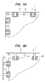
- FIGS. 6A and 6B are schematic views of a radiation detecting apparatus using, as a buffer unit, a surface member formed from CFRP and a shock absorber using a gas pressure.
- FIGS. 7A and 7B are schematic views of a radiation detecting apparatus using, as a buffer unit, a surface member formed from sheet shaped polyurethane fiber and a plate spring.
- FIG. 8 is a schematic view of an embodiment of a radiation detecting system including a radiation detecting apparatus according to the present invention.
- FIG. 1 is an appearance view of an embodiment of a radiation detecting apparatus according to the present invention.
- FIG. 2 is a circuit block diagram of the embodiment of the radiation detecting apparatus according to the present invention.
- the radiation detecting apparatus 1 of the embodiment includes a casing 2 having a handle 5 .
- the casing 2 includes at least a sensor panel 10 , a control circuit portion 11 , and a battery 18 for supplying electric power to the control circuit portion 11 .
- the control circuit portion 11 includes a drive circuit 12 of the sensor panel 10 , a read out circuit 13 of a signal derived from the sensor panel 10 , and a control portion connected to the drive circuit 12 and the read out circuit 13 .
- control circuit portion 11 includes a determining unit 19 for determining a state of the radiation detecting apparatus 1 .
- the determining unit 19 determines, based on a signal transmitted from an acceleration detecting unit described later, whether the radiation detecting apparatus 1 in moving is in an excessively accelerated state, a free falling state or a normal state.
- the determining unit 19 includes a circuit such as a comparator. The comparator compares a preset signal with a signal transmitted by an acceleration detecting means, and outputs a different value by a result of the comparing.
- an acceleration detecting unit (acceleration sensor 14 ), a memory 15 , and a buffer unit 16 for operating according to a signal from the determining unit 19 are connected.
- the acceleration sensor 14 has a function of detecting an acceleration relating to the movement of the radiation detecting apparatus 1 , and transmitting a signal based on a value of the acceleration to the determining unit 19 .
- the memory 15 stores a value of a criterion used when the determining unit 19 determines the state of the radiation detecting apparatus 1 , and the determining unit 19 compares the criterion value with the obtained value of the acceleration for determination.
- the buffer unit 16 is a member for protecting the radiation apparatus 1 from a shock such as falling. The buffer unit 16 will be described later in more detail.
- a state display unit 3 for displaying that the buffer unit 16 operates according to the signal from the determining unit 19 , and a holding switch 4 for holding the operating buffer unit 16 in the radiation detecting apparatus 1 are connected.
- the state display unit 3 and the holding switch 4 can be provided, for example, on the handle 5 as in FIG. 1 so as to be externally checked and operated.
- an LED or a liquid crystal display apparatus can be used.
- a communication unit 17 for transmitting and receiving data to and from an external device is connected.
- an external connection terminal is placed in the casing 2 with wires, and a transmitting and receiving circuit including an antenna is placed in the casing 2 without wires.
- the battery 18 supplies electric power to the control circuit portion 11 and the components connected to the control circuit portion 11 .
- an indirect conversion type sensor panel can be used in which a plurality of pixels having photoelectric conversion elements and TFTs is placed on a glass substrate, and that detects light converted from radiation into visible light by a scintillator.
- a direct conversion type sensor panel can be used in which a TFT array is placed on a glass substrate, and that coverts radiation into an electric charge with a-Se of the TFT array.
- the radiation refers to X-ray, ⁇ -ray, ⁇ -ray, and ⁇ -ray.
- acceleration detecting unit As the acceleration detecting unit (acceleration sensor 14 ), a general MEMS acceleration sensor of a piezoresistance type, capacitance type, or heat detection type can be used.
- the buffer unit 16 is provided on an outer surface of the casing 2 of the radiation detecting apparatus 1 , and is a member for expanding outward to absorb a shock.
- An example is an air bag.
- Another example is a buffer unit including a surface member that first comes into contact with a floor at a time of falling, and an elastic member such as an oil or gas pressure or a spring for lessening a shock.
- the surface member can be formed from plastic or metal, and desirably formed from light and strong CFRP or KFRP.
- the surface member can be also formed from a sheet shaped stretch material of synthetic fiber such as nylon, aramid and polyurethane.
- the elastic member is used for further lessening a shock at a time of falling, and selected from a shock absorber using a gas or oil pressure, an air bag, a rubber, a coil spring, and a plate spring.
- the buffer unit 16 When the buffer unit 16 is placed on a radiation incident side of the radiation detecting apparatus 1 , the buffer unit 16 can be adjusted in its material and thickness so as to easily transmit radiation.
- a surface member formed from aluminum having a thickness of 100 ⁇ m transmits 90% of X-ray of 50 keV.
- the buffer unit can be formed from a material with little effect on an image such as an artifact.
- the buffer unit can be formed from CFRP, KFRP, and a sheet shaped stretch material of synthetic fiber such as nylon, aramid and polyurethane.
- the buffer unit can have a structure with small surface distribution such as a uniform thickness.
- FIG. 3 is a flowchart illustrating an operation of the radiation detecting apparatus in FIGS. 1 and 2 .
- Step 101 it is determined whether the radiation detecting apparatus 1 is connected (mounted) to the other device such as a C arm or a frame for an standing or recumbent position.
- the C arm is an apparatus having a C-shaped rotatable holder mainly for radiographing of X-ray moving images, and an X-ray source is fixed to one end of the C-shaped holder and the detecting apparatus is fixed to the other end.
- the determining unit 19 in the control circuit portion 11 determines the connection via the communication unit 17 in the radiation detecting apparatus, for example, from a signal transmitted from an external PC and indicating a connection state.
- the radiation detecting apparatus 1 has a low possibility of breakage due to falling, and thus it is determined that the radiation detecting apparatus 1 is in a preset normal state, and the process proceeds to Step 106 . Without the connection, the process proceeds to Step 102 .
- Step 102 it is determined whether the radiation detecting apparatus 1 is in an excessively accelerated state.
- the determining unit 19 determines whether a value of an acceleration of the radiation detecting apparatus 1 obtained from the acceleration detecting unit (acceleration sensor 14 ) is in an excessively accelerated state (state with an acceleration higher than 1 G).
- the determining unit 19 determines that the value is in the excessively accelerated state, the process proceeds to Step 103 , and the buffer unit 16 operates.
- the acceleration is 1 G or lower, the process proceeds to Step 104 .
- Step 104 it is determined whether the radiation detecting apparatus 1 is in a free falling state. Whether the radiation detecting apparatus 1 is in the free falling state is determined based on a gravity acceleration and a time thereof. For example, a case where a microgravity state lasts for 0.26 seconds is regarded as free falling. This is because when a falling height of the radiation detecting apparatus 1 provided on a bed in a recumbent position is about 35 cm, a falling time of the radiation detecting apparatus 1 is 0.27 seconds. In this case, the determining unit 19 determines that the radiation detecting apparatus 1 is in the free falling state when the microgravity state lasts for 0.26, the process proceeds to Step 105 , and the buffer unit 16 operates.
- the values of the criterion height and falling time are not limited to the above described values but can be selected by a user because a placement position of the radiation detecting apparatus may differ according to the state of use of the apparatus.
- the values for determination criteria in Steps 102 and 104 are stored in a memory of the determining unit 19 itself, or used by the determining unit 19 reading data stored in the memory 15 connected to the control circuit portion 11 .
- the control circuit portion 11 When it is determined by the above described determination flow that the radiation detecting apparatus 1 is in the excessively accelerated state or the free falling state, the control circuit portion 11 sends a signal for operating the buffer unit 16 . Thus, the buffer unit 16 operates so as to protect the radiation apparatus 1 . When it is determined by the above described determination flow that the radiation detecting apparatus 1 is in the normal state, the control circuit portion 11 does not send a signal to the buffer unit 16 .
- FIGS. 4A and 4B illustrate a radiation detecting apparatus including an air bag module as a buffer unit.
- the air bag module includes an air bag 20 and an inflator 30 .
- the inflator 30 provides a gas into the air bag 20 , and the air bag 20 is inflated by the gas provided by the inflator 30 .
- FIG. 4A illustrates the radiation detecting apparatus in a normal state.
- the control circuit portion sends a signal to the air bag module as the buffer unit, the inflator 30 provides a gas into the air bag 20 to inflate the air bag 20 as illustrated in FIG. 4B to absorb a shock.
- FIG. 4A and 4B illustrate an example where the air bag 20 is placed on one surface of the radiation detecting apparatus, but providing air bags 20 on all surfaces increases safety.
- An air bag 20 inflated so as to have a thickness larger than a thickness of the apparatus can be desirably provided at a corner of the radiation detecting apparatus in FIG. 1 because of little effect on radiation use efficiency and images.
- FIGS. 5A and 5B illustrate a radiation detecting apparatus using, as a buffer unit, a surface member 21 formed from CFRP (carbon fiber reinforced plastic) and an elastic member formed of a coil spring 22 .
- FIG. 5A illustrates a corner of the radiation detecting apparatus in a normal state with a metal spring being contracted and fixed by a fixing unit 23 .
- a fixing unit 23 a mechanical unit such as a hook combined with a cam or a magnetic unit such as a magnet is used.
- An electromagnetic unit such as a solenoid for holding with an attracting force of a permanent magnet can be used, and the solenoid when used can also serve as an elastic member.
- the control circuit portion When it is determined whether the radiation detecting apparatus is in an excessively accelerated state or a free falling state, the control circuit portion sends a signal to the buffer unit, the fixing unit is opened as in FIG. 5B , and the coil spring 22 extends to absorb a shock.
- FIGS. 6A and 6B illustrate a radiation detecting apparatus using, as a buffer unit, a surface member 21 formed from CFRP and an elastic member formed of a shock absorber 24 using a gas pressure.
- FIG. 6A illustrates a corner of the radiation detecting apparatus in a normal state with the gas pressure being reduced and the shock absorber 24 being contracted and fixed by a fixing unit 23 .
- the control circuit portion sends a signal to the buffer unit, the fixing unit is opened as illustrated in FIG. 6B , and the gas pressure is applied to the shock absorber to absorb a shock at a time of falling.
- FIGS. 7A and 7B illustrate a radiation detecting apparatus using, as a buffer unit, a surface member 25 formed from sheet shaped polyurethane fiber and an elastic member formed of a plate spring 26 .
- FIG. 6A illustrates a cross section of the radiation detecting apparatus in a normal state with the plate spring 26 being deformed and fixed by a fixing unit (not shown).
- the control circuit portion sends a signal to the buffer unit, the fixing unit is opened as illustrated in FIG. 7B , and the plate spring 26 expands the surface member 25 formed from the sheet shaped polyurethane fiber to absorb a shock.
- the buffer unit can be provided in any portions beside the corner and the radiation incident side of the radiation detecting apparatus.
- the buffer unit can be restored in conjunction with the holding switch 4 in FIG. 1 .
- a solenoid as a lock mechanism allows the buffer unit to be restored by controlling a current flowing through a coil of the solenoid.
- the present invention is not limited to the detailed examples in FIGS. 4A to 7B , and configurations can be combined that can prevent an increase in the size of the radiation detecting apparatus and reduce the possibility of breakage when a shock such as falling is exerted on the radiation detecting apparatus.
- X-ray 6060 generated by a radiation source 6050 passes through the chest 6062 to be observed of a patient or a human subject 6061 , and enters a radiation detecting apparatus 6040 including a sensor panel having a scintillator and a photoelectric conversion element.
- the entering X-ray includes information on the inside of the body of the human subject 6061 .
- the scintillator emits light in response to the entry of the X-ray, and photoelectrically converts the light to obtain electrical information.
- the information is converted into digital form, subjected to an image processing by an image processor 6070 as a signal processing unit, and can be observed on a display 6080 as a display unit in a control room.
- the information can be transferred to a remote place by a transmission processing unit such as a telephone line 6090 , and be displayed on a display 6081 as a display unit in a doctor room in a different place or stored in a recording unit such as an optical disk. This allows diagnosis by a doctor in a remote place.
- a film processor 6100 as a recording unit can record the information in a film 6110 as a recording medium.
- the communication unit 17 sends a signal to a signal processing unit or a radiation source with or without wires to control so that the radiation source does not emit X-ray. This can prevent emission of the X-ray when there is a problem in the radiation detecting apparatus and increases safety.
- the present invention can be applied to a medical digital X-ray detecting apparatus, and can be also effectively applied to a digital radiation detecting apparatus for non-destructive inspection or other uses with radiation.
Landscapes
- Physics & Mathematics (AREA)
- General Physics & Mathematics (AREA)
- Measurement Of Radiation (AREA)
- Radiography Using Non-Light Waves (AREA)
- Apparatus For Radiation Diagnosis (AREA)
Applications Claiming Priority (3)
| Application Number | Priority Date | Filing Date | Title |
|---|---|---|---|
| JP2008144448A JP4847492B2 (ja) | 2008-06-02 | 2008-06-02 | 放射線検出装置及び放射線検出システム並びにそれらの制御方法 |
| JP2008-144448 | 2008-06-02 | ||
| PCT/JP2009/060296 WO2009148143A1 (en) | 2008-06-02 | 2009-05-29 | Radiation detecting apparatus and radiation detecting system |
Publications (2)
| Publication Number | Publication Date |
|---|---|
| US20110038111A1 US20110038111A1 (en) | 2011-02-17 |
| US8563939B2 true US8563939B2 (en) | 2013-10-22 |
Family
ID=41066504
Family Applications (1)
| Application Number | Title | Priority Date | Filing Date |
|---|---|---|---|
| US12/988,803 Expired - Fee Related US8563939B2 (en) | 2008-06-02 | 2009-05-29 | Radiation detecting apparatus and radiation detecting system |
Country Status (3)
| Country | Link |
|---|---|
| US (1) | US8563939B2 (https=) |
| JP (1) | JP4847492B2 (https=) |
| WO (1) | WO2009148143A1 (https=) |
Cited By (2)
| Publication number | Priority date | Publication date | Assignee | Title |
|---|---|---|---|---|
| US20210048543A1 (en) * | 2019-08-13 | 2021-02-18 | Vieworks Co., Ltd. | X-ray detector cover and x-ray detector having same |
| US11333777B2 (en) * | 2019-04-19 | 2022-05-17 | Canon Kabushiki Kaisha | Radiation imaging apparatus with improved impact resistance |
Families Citing this family (9)
| Publication number | Priority date | Publication date | Assignee | Title |
|---|---|---|---|---|
| JP2010156598A (ja) * | 2008-12-26 | 2010-07-15 | Fujifilm Corp | 可搬型放射線画像撮影装置 |
| JP5536527B2 (ja) * | 2010-04-30 | 2014-07-02 | 富士フイルム株式会社 | 放射線画像撮影装置及び放射線画像撮影システム |
| CN102870008A (zh) * | 2010-04-30 | 2013-01-09 | 富士胶片株式会社 | 辐射成像装置、辐射成像系统和用于将辐射转换板固定在辐射成像装置中的方法 |
| JP5466082B2 (ja) * | 2010-05-25 | 2014-04-09 | 富士フイルム株式会社 | 放射線画像撮影装置、放射線画像撮影システム、及び、放射線画像撮影装置における放射線変換パネルの固定方法 |
| JP2012050596A (ja) * | 2010-08-31 | 2012-03-15 | Fujifilm Corp | 放射線撮影装置 |
| JP2012154696A (ja) | 2011-01-24 | 2012-08-16 | Canon Inc | シンチレータパネル、放射線検出装置およびそれらの製造方法 |
| JP2014163904A (ja) * | 2013-02-27 | 2014-09-08 | Nok Corp | 電子カセッテ用緩衝材 |
| KR102544251B1 (ko) * | 2018-07-24 | 2023-06-16 | 삼성전자주식회사 | 충격 감지 센서를 포함하는 엑스선 디텍터, 엑스선 디텍터를 포함하는 엑스선 시스템 및 그 동작 방법 |
| CN111526239B (zh) * | 2020-06-10 | 2021-02-02 | 广东冠迪生物科技有限公司 | 一种可防摔的手机壳 |
Citations (13)
| Publication number | Priority date | Publication date | Assignee | Title |
|---|---|---|---|---|
| US6600157B2 (en) | 2000-06-27 | 2003-07-29 | Canon Kabushiki Kaisha | Semiconductor device, and radiation detection device and radiation detection system having same |
| US6608312B1 (en) | 1999-09-03 | 2003-08-19 | Canon Kabushiki Kaisha | Information reading apparatus, method of producing same, and radiation imaging system having same |
| JP2004361879A (ja) | 2003-06-09 | 2004-12-24 | Fuji Photo Film Co Ltd | 放射線検出用カセッテ |
| JP2005003755A (ja) | 2003-06-10 | 2005-01-06 | Fuji Photo Film Co Ltd | 画像情報検出用カセッテ |
| JP2005006806A (ja) | 2003-06-18 | 2005-01-13 | Canon Inc | X線撮影装置 |
| US6940078B2 (en) | 2002-02-25 | 2005-09-06 | Fuji Photo Film Co., Ltd. | State detecting device for sheet-like image recording medium |
| JP2006113053A (ja) | 2004-10-04 | 2006-04-27 | General Electric Co <Ge> | 衝撃吸収性カバーを設けたx線検出器 |
| JP2006251196A (ja) | 2005-03-09 | 2006-09-21 | Fuji Photo Film Co Ltd | 撮像装置 |
| US20060212986A1 (en) | 2005-03-23 | 2006-09-28 | Ivoice, Inc. | Pedestrian air bag device |
| US20070085015A1 (en) | 2005-10-14 | 2007-04-19 | Castleberry Donald E | Lightweight and rugged digital x-ray detector |
| WO2008054717A2 (en) | 2006-11-02 | 2008-05-08 | Carestream Health, Inc. | Position sensing apparatus for radiation imaging system |
| US7514703B2 (en) | 2003-06-10 | 2009-04-07 | Fujifilm Corporation | Image information detecting cassette |
| US7548168B2 (en) | 2005-05-24 | 2009-06-16 | Searete Llc | Wearable/portable protection for a body |
-
2008
- 2008-06-02 JP JP2008144448A patent/JP4847492B2/ja not_active Expired - Fee Related
-
2009
- 2009-05-29 WO PCT/JP2009/060296 patent/WO2009148143A1/en not_active Ceased
- 2009-05-29 US US12/988,803 patent/US8563939B2/en not_active Expired - Fee Related
Patent Citations (14)
| Publication number | Priority date | Publication date | Assignee | Title |
|---|---|---|---|---|
| US6608312B1 (en) | 1999-09-03 | 2003-08-19 | Canon Kabushiki Kaisha | Information reading apparatus, method of producing same, and radiation imaging system having same |
| US6600157B2 (en) | 2000-06-27 | 2003-07-29 | Canon Kabushiki Kaisha | Semiconductor device, and radiation detection device and radiation detection system having same |
| US6940078B2 (en) | 2002-02-25 | 2005-09-06 | Fuji Photo Film Co., Ltd. | State detecting device for sheet-like image recording medium |
| JP2004361879A (ja) | 2003-06-09 | 2004-12-24 | Fuji Photo Film Co Ltd | 放射線検出用カセッテ |
| US7183556B2 (en) | 2003-06-09 | 2007-02-27 | Fuji Photo Film Co., Ltd. | Radiation detecting cassette |
| JP2005003755A (ja) | 2003-06-10 | 2005-01-06 | Fuji Photo Film Co Ltd | 画像情報検出用カセッテ |
| US7514703B2 (en) | 2003-06-10 | 2009-04-07 | Fujifilm Corporation | Image information detecting cassette |
| JP2005006806A (ja) | 2003-06-18 | 2005-01-13 | Canon Inc | X線撮影装置 |
| JP2006113053A (ja) | 2004-10-04 | 2006-04-27 | General Electric Co <Ge> | 衝撃吸収性カバーを設けたx線検出器 |
| JP2006251196A (ja) | 2005-03-09 | 2006-09-21 | Fuji Photo Film Co Ltd | 撮像装置 |
| US20060212986A1 (en) | 2005-03-23 | 2006-09-28 | Ivoice, Inc. | Pedestrian air bag device |
| US7548168B2 (en) | 2005-05-24 | 2009-06-16 | Searete Llc | Wearable/portable protection for a body |
| US20070085015A1 (en) | 2005-10-14 | 2007-04-19 | Castleberry Donald E | Lightweight and rugged digital x-ray detector |
| WO2008054717A2 (en) | 2006-11-02 | 2008-05-08 | Carestream Health, Inc. | Position sensing apparatus for radiation imaging system |
Non-Patent Citations (1)
| Title |
|---|
| PCT International Search Report and Written Opinion of the International Searching Authority, International Application No. PCT/JP2009/060296, Mailing Date Sep. 30, 2009. |
Cited By (2)
| Publication number | Priority date | Publication date | Assignee | Title |
|---|---|---|---|---|
| US11333777B2 (en) * | 2019-04-19 | 2022-05-17 | Canon Kabushiki Kaisha | Radiation imaging apparatus with improved impact resistance |
| US20210048543A1 (en) * | 2019-08-13 | 2021-02-18 | Vieworks Co., Ltd. | X-ray detector cover and x-ray detector having same |
Also Published As
| Publication number | Publication date |
|---|---|
| JP4847492B2 (ja) | 2011-12-28 |
| JP2009293921A (ja) | 2009-12-17 |
| WO2009148143A1 (en) | 2009-12-10 |
| US20110038111A1 (en) | 2011-02-17 |
Similar Documents
| Publication | Publication Date | Title |
|---|---|---|
| US8563939B2 (en) | Radiation detecting apparatus and radiation detecting system | |
| US7127032B1 (en) | X-ray detector having an accelerometer | |
| EP2040621B1 (en) | Radiographic apparatus | |
| JP5110784B2 (ja) | 衝撃吸収性カバーを設けたx線検出器 | |
| US20120250826A1 (en) | Radiographic imaging apparatus | |
| US7581885B2 (en) | Method and system of aligning x-ray detector for data acquisition | |
| JP4831566B2 (ja) | 動的環境制御を設けた放射線撮像用検出器ドッキング・ステーション | |
| US7696484B2 (en) | Electronic cassette type of radiation detection apparatus | |
| EP2883086B1 (en) | Digital x-ray detector assembly with elastomeric backscatter shield | |
| JP2009034428A (ja) | X線撮影システム | |
| CN102551752A (zh) | 辐射图像检测设备和用于控制辐射图像检测设备的方法 | |
| JP4715844B2 (ja) | 放射線画像撮影システム | |
| US20070085015A1 (en) | Lightweight and rugged digital x-ray detector | |
| JP2012132703A (ja) | 電子カセッテ | |
| JP2012150320A (ja) | 放射線画像検出カセッテ | |
| JP5509558B2 (ja) | 放射線画像撮影システム | |
| JP2006250728A (ja) | 放射線画像検出器及び放射線画像撮影システム | |
| JP2010156598A (ja) | 可搬型放射線画像撮影装置 | |
| JP2008212343A (ja) | 軽量で頑丈なディジタルx線検出器 | |
| US7377172B2 (en) | Method and system for impact detection of an imaging system | |
| JP2012205850A (ja) | 電子カセッテの輸送情報取得方法およびシステム | |
| JP5300453B2 (ja) | 放射線画像撮影システムおよびプログラム | |
| JP2005177379A (ja) | 放射線画像撮影装置 | |
| US12419594B2 (en) | Radiographing apparatus | |
| JP2018205242A (ja) | 放射線撮影装置 |
Legal Events
| Date | Code | Title | Description |
|---|---|---|---|
| AS | Assignment |
Owner name: CANON KABUSHIKI KAISHA, JAPAN Free format text: ASSIGNMENT OF ASSIGNORS INTEREST;ASSIGNORS:OKADA, SATOSHI;INOUE, MASATO;NAGANO, KAZUMI;AND OTHERS;REEL/FRAME:025424/0643 Effective date: 20100910 |
|
| STCF | Information on status: patent grant |
Free format text: PATENTED CASE |
|
| FEPP | Fee payment procedure |
Free format text: PAYOR NUMBER ASSIGNED (ORIGINAL EVENT CODE: ASPN); ENTITY STATUS OF PATENT OWNER: LARGE ENTITY |
|
| FPAY | Fee payment |
Year of fee payment: 4 |
|
| FEPP | Fee payment procedure |
Free format text: MAINTENANCE FEE REMINDER MAILED (ORIGINAL EVENT CODE: REM.); ENTITY STATUS OF PATENT OWNER: LARGE ENTITY |
|
| LAPS | Lapse for failure to pay maintenance fees |
Free format text: PATENT EXPIRED FOR FAILURE TO PAY MAINTENANCE FEES (ORIGINAL EVENT CODE: EXP.); ENTITY STATUS OF PATENT OWNER: LARGE ENTITY |
|
| STCH | Information on status: patent discontinuation |
Free format text: PATENT EXPIRED DUE TO NONPAYMENT OF MAINTENANCE FEES UNDER 37 CFR 1.362 |
|
| FP | Lapsed due to failure to pay maintenance fee |
Effective date: 20211022 |