US8544829B2 - Adjustment safeguard - Google Patents
Adjustment safeguard Download PDFInfo
- Publication number
- US8544829B2 US8544829B2 US13/074,038 US201113074038A US8544829B2 US 8544829 B2 US8544829 B2 US 8544829B2 US 201113074038 A US201113074038 A US 201113074038A US 8544829 B2 US8544829 B2 US 8544829B2
- Authority
- US
- United States
- Prior art keywords
- top part
- cap
- sleeve
- bottom part
- adjustment safeguard
- Prior art date
- Legal status (The legal status is an assumption and is not a legal conclusion. Google has not performed a legal analysis and makes no representation as to the accuracy of the status listed.)
- Active, expires
Links
Images


Classifications
-
- F—MECHANICAL ENGINEERING; LIGHTING; HEATING; WEAPONS; BLASTING
- F02—COMBUSTION ENGINES; HOT-GAS OR COMBUSTION-PRODUCT ENGINE PLANTS
- F02M—SUPPLYING COMBUSTION ENGINES IN GENERAL WITH COMBUSTIBLE MIXTURES OR CONSTITUENTS THEREOF
- F02M19/00—Details, component parts, or accessories of carburettors, not provided for in, or of interest apart from, the apparatus of groups F02M1/00 - F02M17/00
- F02M19/04—Fuel-metering pins or needles
-
- F—MECHANICAL ENGINEERING; LIGHTING; HEATING; WEAPONS; BLASTING
- F02—COMBUSTION ENGINES; HOT-GAS OR COMBUSTION-PRODUCT ENGINE PLANTS
- F02M—SUPPLYING COMBUSTION ENGINES IN GENERAL WITH COMBUSTIBLE MIXTURES OR CONSTITUENTS THEREOF
- F02M3/00—Idling devices for carburettors
- F02M3/02—Preventing flow of idling fuel
-
- F—MECHANICAL ENGINEERING; LIGHTING; HEATING; WEAPONS; BLASTING
- F02—COMBUSTION ENGINES; HOT-GAS OR COMBUSTION-PRODUCT ENGINE PLANTS
- F02M—SUPPLYING COMBUSTION ENGINES IN GENERAL WITH COMBUSTIBLE MIXTURES OR CONSTITUENTS THEREOF
- F02M3/00—Idling devices for carburettors
- F02M3/08—Other details of idling devices
- F02M3/10—Fuel metering pins; Nozzles
-
- Y—GENERAL TAGGING OF NEW TECHNOLOGICAL DEVELOPMENTS; GENERAL TAGGING OF CROSS-SECTIONAL TECHNOLOGIES SPANNING OVER SEVERAL SECTIONS OF THE IPC; TECHNICAL SUBJECTS COVERED BY FORMER USPC CROSS-REFERENCE ART COLLECTIONS [XRACs] AND DIGESTS
- Y10—TECHNICAL SUBJECTS COVERED BY FORMER USPC
- Y10T—TECHNICAL SUBJECTS COVERED BY FORMER US CLASSIFICATION
- Y10T137/00—Fluid handling
- Y10T137/6851—With casing, support, protector or static constructional installations
- Y10T137/7043—Guards and shields
- Y10T137/7062—Valve guards
- Y10T137/7065—With means for accommodating a detachable actuator
Definitions
- the invention relates to an adjustment safeguard for a set screw that is rotatably supported in a housing, in particular for a set screw of a carburetor such as a diaphragm carburetor or the like of a hand-guided power tool such as a motor chainsaw or the like.
- the adjustment safeguard comprises a cap that is non-rotatably secured on the head of the set screw, wherein the cap is surrounded with minimal radial play by an approximately coaxially positioned sleeve, fast with the carburetor housing, and is received in the sleeve across its axial length.
- the cap has a projection that has correlated therewith a stop disposed in the rotational direction of the set screw inside the sleeve and fast with the carburetor housing.
- U.S. Pat. No. 5,252,261 discloses an adjustment safeguard for the adjusting needle (set screw) of a carburetor that is comprised of a cap fixedly secured on the head of the set screw and surrounded with minimal radial play by a coaxially positioned sleeve fast with the carburetor housing.
- the cap has in rotational direction of the set screw a stop that is fast with the carburetor housing so that after positioning of the cap the user can adjust the set screw only by a limited rotational angle.
- the cap is pushed onto a knurled section of the set screw and is fixedly (non-rotatably) connected to the set screw, i.e., does not rotate relative to the set screw. Axially, the cap is secured only by friction so that it can be easily removed by the user by a lever action and the rotational limitation of the set screw can thus be canceled easily.
- the cap is comprised of a top part and a bottom part that is separate from the top part, wherein the bottom part is secured axially and non-rotatably on the head of the set screw and the bottom part engages with form fit the top part in rotational direction and is axially connected to the top part.
- the stop pin has correlated therewith an L-shaped or T-shaped guide provided on the outer circumference of the top part, wherein an axial longitudinal groove extends approximately across the length of the top part and passes into a circumferential groove of the top part.
- the grooves are matched with respect to their width approximately to the dimension (diameter, width) of the stop pin engaging the grooves.
- the position of the circumferential groove is selected such that a rotation of the cap, together with the adjusting needle, is possible when, and only when, the cap has been pushed completely into the sleeve and the bottom part is locked axially captively on the set screw. Only when this is accomplished, the stop pin is properly positioned in the circumferential groove so that only then rotation of the cap over a limited rotation angle is possible.
- the longitudinal groove opens at one end of the circumferential groove into the circumferential groove wherein the circumferential groove is positioned below a terminal collar on the external end face of the top part. In this way, it is ensured that the cap is always pushed completely into the sleeve so that its proper function is possible.
- the circumferential groove extends about a circumferential angle of approximately 270 degrees.
- the bottom part of the cap is made of plastic material while the top part of cap is comprised of metal, in particular light metal, expediently zinc.
- the bottom part is axially captively locked on the top part.
- the bottom part engages with inner radial locking elements a circumferential groove on the head of the set screw and with outer radial locking elements the locking cutouts of the top part. In this way, the bottom part is locked axially on the set screw as well as axially on the top part.
- a central opening is provided on the top part that has positioned opposite thereto a tool support surface provided on the head of the set screw.
- FIG. 4 is a view of the adjustment safeguard according to FIG. 3 looking onto the bottom part.
- FIG. 5 is a view of the adjustment safeguard according to the invention with joined top part and bottom part.
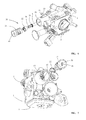
- FIG. 7 is a view onto the carburetor according to FIG. 6 with the adjustment safeguard illustrated in an exploded view.
- FIG. 8 is a section view of the carburetor according to FIG. 6 .
- FIG. 10 shows the adjustment safeguard according to FIG. 9 in a view onto the bottom part.
- FIG. 11 shows the adjustment safeguard according to FIG. 10 with joined top and bottom parts.
- FIG. 12 is a view onto the guide provided in the top part of the adjustment safeguard according to FIG. 11 .
- FIG. 1 illustrates a carburetor 1 which is comprised of a carburetor body or housing with an intake passage 2 formed therein.
- a fuel nozzle 3 opens into the intake passage 2 that is supplied with fuel from a fuel passage 4 .
- the tip of an adjusting needle 5 projects into the fuel passage 4 ; the adjusting needle 5 is used for adjusting the fuel cross-section of the fuel passage 4 and is position-adjustable in the thread 6 by being screwed in or out.
- the adjusting needle 5 is thus embodied as a set screw.
- the illustrated carburetor 1 is a so-called diaphragm carburetor having on one housing side a fuel pump 7 for conveying the fuel and on its other housing side a control chamber 8 with a control valve 9 for providing a uniform pressure in the control chamber 8 .
- the control valve 9 is actuated by a control diaphragm 10 that delimits the control chamber 8 .
- the air pressure existing on the clean side of an air filter is acting on the side 11 of the diaphragm 10 that is facing away from the control chamber 8 .
- a connecting socket 12 is provided for this purpose.
- the under pressure in the intake passage 2 is determined based on the position of the throttle 13 secured on a shaft 14 supported within the carburetor housing.
- an adjusting lever 15 the throttle shaft 14 is adjusted by an actuating device, not illustrated in detail, in order to adjust the throttle 13 from an idle position ( FIG. 2 ) into a full throttle position.
- the maximum fuel quantity that enters at full load the intake passage 2 through the fuel nozzle 3 is determined by the adjusting needle (set screw) 5 .
- An internal combustion engine that is provided with such a carburetor 1 for example, a two-stroke engine that is installed in a hand-guided power tool such as a motor chain saw, a cut-off machine, a trimmer, a hedge trimmer or a similar portable hand-guided power tool, is adjusted by the manufacturer before being delivered to a permissible maximum fuel quantity in order to ensure that the user will not adjust the engine to a have a fuel/air mixture that is too rich.
- a hand-guided power tool such as a motor chain saw, a cut-off machine, a trimmer, a hedge trimmer or a similar portable hand-guided power tool
- a tool engaging area 17 for example, a polygon socket such as a hexagon socket for engagement by a polygon key or hexagon key (Allen key).
- a rotation of the adjusting needle (set screw) 5 by a user should be allowed only within narrow limits.
- an adjustment safeguard in the form of a cap 20 is attached that, with minimal radial play r, is received in a coaxial sleeve 18 so that it is safe from manipulation.
- the sleeve 18 is a component that is fast with the carburetor 1 .
- the sleeve 18 is embodied as a monolithic part of the main body or housing of the carburetor 1 .
- the axial height L of the sleeve 18 is designed such that the cap 20 across its axial length k is received in the sleeve 18 .
- the length L of the sleeve 18 is greater than the axial length k of the cap 20 wherein the sleeve 18 surrounds the cap 20 coaxially with tight fit so that manipulation by a user without destruction of the cap 20 is impossible.
- the cap 20 is comprised, as shown in FIGS. 1 to 5 , of a top part 21 and a bottom part 22 . Looking at FIGS. 4 and 5 , it is apparent that the bottom part 22 is an internal part and the top part 21 is an external part. The bottom part 22 is pushed or inserted into the top part 21 .
- the bottom part 22 is comprised of a knurled ring 24 that comprises an inner toothing 26 (for example, a knurling) that has correlated therewith an appropriate toothing 19 (for example, a complementary knurling) on the outer circumference of the adjusting needle 5 .
- an inner toothing 26 for example, a knurling
- an appropriate toothing 19 for example, a complementary knurling
- the top part 21 has the shape of a bushing having a bottom 23 that forms an outer end face.
- the bottom part 22 as shown in FIGS. 4 and 5 , is inserted into the top part 21 wherein a rotation pin 32 of the bottom part 22 engages a recess 25 of the top part 21 .
- the recess 25 is formed on the end that is facing the adjusting needle 5 and is open at the end 27 so that the rotation pin 32 can be pushed axially into the recess 25 .
- locking ribs 34 are formed wherein, relative to the longitudinal axis of the set screw 5 , two locking ribs 34 are positioned diametrically opposite each other.
- the locking ribs 34 engage looking cutouts 35 that are provided in the wall 29 of the top part 21 and effect an axial securing action of the bottom part 22 on the top part 21 .
- the bottom part 22 is axially captively connected to the top part 21 .
- the locking elements 30 and the locking ribs 34 are expediently provided on a common locking tongue 36 of the bottom part 22 .
- the top part 21 of the cap 20 has a section that is embodied about a circumferential angle 31 so as to have a smaller outer diameter than the wall section 33 .
- a stop in the form of a stop rib 40 projects that is provided on the inner circumference 41 of the sleeve 18 .
- the stop rib 40 projects axially parallel to the longitudinal axis 42 of the adjusting needle 5 to a point that is minimally spaced from the terminal collar 37 of the bottom 23 of the top part 21 .
- a marking 39 is provided on the collar 37 .
- the marking 39 is aligned approximately with the stop rib 40 and the cap 20 is pushed into the sleeve 18 .
- a positional securing element 43 is formed on the bottom part 22 . The positional securing element 43 , after the bottom part 22 has been inserted into the top part 21 , is resting in a cutout 44 at the end of the top part 21 .
- FIGS. 6 through 12 A further embodiment of an adjustment safeguard according to the invention is illustrated in FIGS. 6 through 12 .
- a stop in the form of a stop pin 61 is provided that is secured in a receptacle 60 of the sleeve 18 and projects radially into the interior of the sleeve 18 .
- the basic configuration of the carburetor and of the adjusting device corresponds to that of FIGS. 1 to 5 so that for same parts same reference numerals are employed.
- the stop pin 61 is positioned near the open end of the sleeve 18 immediately behind the terminal collar 37 of the top part 21 of the inserted cap 20 provided as an adjustment safeguard.
- the bottom part 22 is identical to that of FIGS. 3 to 5 .
- the bottom part 22 is inserted into the bushing-shaped top part 21 wherein a radial rotation pin 32 engages an axial recess 25 of the top part 21 so that the bottom part 22 is connected fixedly with the top part 21 for common rotation.
- the top part has at its open free end 27 an outer radius A that is greater than the spacing R ( FIG. 8 ) of the pin from the longitudinal axis 42 of the adjusting needle 5 . This corresponds approximately to the embodiment as it is illustrated in dashed lines in FIG. 5 .
- a mounting guide is provided that comprises a longitudinal groove 62 open at end 27 and, as shown in FIG. 12 , extending toward the terminal collar 37 across the length of the top part 21 .
- the longitudinal groove 62 in the area of the end 27 of the top part 21 is provided with a greater width B 1 than at the end that is facing the terminal collar 37 where it has a smaller width B 2 .
- the longitudinal groove 62 tapers uniformly from the end 27 of the top part 21 toward the terminal collar 37 of the top parts 21 .
- a circumferential groove 63 is formed that extends about a circumferential angle 31 of approximately 270 degrees.
- the longitudinal groove 62 opens at an end of the circumferential groove 63 so that an approximately L-shaped guide is provided on the outer circumference of the top part 21 .
- the cap 20 is inserted into the sleeve 18 wherein the rotational position upon insertion of the cap 20 must be aligned such that the stop pin 61 can enter the open end of the longitudinal groove 62 at the end of the top part 21 .
- the greater width B 1 serves for easier threading of the stop pin 61 into the sleeve 18 . Only at the time when the cap 20 has been axially pressed in fixedly, the stop pin 61 rests in the circumferential groove 63 , as indicated in dashed lines in FIG. 12 .
- the working section 53 of the removal tool 51 is embodied as a left-handed thread so that upon screwing in the working section 53 of the removal tool 51 into the central opening 50 the cap 20 is first entrained in rotation until the stop pin 61 hits the end of the circumferential groove 63 and a further rotation is prevented as a result of the pin's position according to FIG. 12 .
- the removal tool can be screwed in completely into the central opening and, as already described in connection with the embodiment of FIGS. 1 through 5 , a spreading force can be applied between the head 16 of the adjusting needle 5 and the top part 21 of the cap 20 until the locking ribs 34 break or deform to thus release the top part 21 from the bottom part 22 .
- the top part 21 of the cap 20 is made of metal, in particular light metal, and the bottom part 22 of the cap 20 is made of plastic material.
- the top part 21 is made of zinc.
Landscapes
- Engineering & Computer Science (AREA)
- Chemical & Material Sciences (AREA)
- Combustion & Propulsion (AREA)
- Mechanical Engineering (AREA)
- General Engineering & Computer Science (AREA)
- Connection Of Plates (AREA)
- Lift Valve (AREA)
- Protection Of Pipes Against Damage, Friction, And Corrosion (AREA)
- Mutual Connection Of Rods And Tubes (AREA)
Applications Claiming Priority (2)
| Application Number | Priority Date | Filing Date | Title |
|---|---|---|---|
| JP2010-274079 | 2010-12-08 | ||
| JP2010274079A JP5773631B2 (ja) | 2010-12-08 | 2010-12-08 | 針弁用リミットキャップ |
Publications (2)
| Publication Number | Publication Date |
|---|---|
| US20120146250A1 US20120146250A1 (en) | 2012-06-14 |
| US8544829B2 true US8544829B2 (en) | 2013-10-01 |
Family
ID=46144715
Family Applications (1)
| Application Number | Title | Priority Date | Filing Date |
|---|---|---|---|
| US13/074,038 Active 2032-04-02 US8544829B2 (en) | 2010-12-08 | 2011-03-29 | Adjustment safeguard |
Country Status (4)
| Country | Link |
|---|---|
| US (1) | US8544829B2 (ja) |
| JP (1) | JP5773631B2 (ja) |
| CN (1) | CN102536518B (ja) |
| DE (1) | DE102011012864B4 (ja) |
Cited By (3)
| Publication number | Priority date | Publication date | Assignee | Title |
|---|---|---|---|---|
| US20160097465A1 (en) * | 2014-10-01 | 2016-04-07 | Emerson Electric Co. | Closures Including Adjustment Tools for Adjustment Mechanisms |
| US20210164419A1 (en) * | 2019-11-28 | 2021-06-03 | Yamabiko Corporation | Limiting cap |
| US11187191B2 (en) * | 2016-06-23 | 2021-11-30 | Walbro Llc | Charge forming device with tamper resistant adjustable valve |
Families Citing this family (5)
| Publication number | Priority date | Publication date | Assignee | Title |
|---|---|---|---|---|
| DE102012019128A1 (de) * | 2012-09-28 | 2014-04-03 | Andreas Stihl Ag & Co. Kg | Verstellsicherung für eine Einstellschraube an einem Vergaser |
| JP6433768B2 (ja) * | 2014-11-25 | 2018-12-05 | ザマ・ジャパン株式会社 | 気化器 |
| US10082107B2 (en) * | 2015-11-06 | 2018-09-25 | Walbro Llc | Carburetor air-fuel mixture adjustment assembly and tools |
| US10738741B2 (en) * | 2016-06-16 | 2020-08-11 | Walbro Llc | Charge forming device with adjustable valve limiter |
| JP6766992B2 (ja) * | 2017-03-02 | 2020-10-14 | ザマ・ジャパン株式会社 | 気化器における調整弁の調整装置 |
Citations (14)
| Publication number | Priority date | Publication date | Assignee | Title |
|---|---|---|---|---|
| US2590217A (en) * | 1948-08-31 | 1952-03-25 | Lucile M Hursh | Combined air filter and needle valve |
| US3618906A (en) * | 1967-08-18 | 1971-11-09 | Ford Motor Co | Device and process for limiting idling fuel in carburetors |
| US3833171A (en) * | 1973-07-18 | 1974-09-03 | Vernay Laboratories | Temperature responsive valve assembly |
| JPS5388422A (en) * | 1977-01-14 | 1978-08-03 | Fuji Heavy Ind Ltd | Sealing device for internal cumbustion engine and so on |
| US4378321A (en) * | 1979-05-15 | 1983-03-29 | Colt Industries Operating Corp. | Tamper proof sealing plug |
| US4853160A (en) * | 1988-10-26 | 1989-08-01 | Outboard Marine Corporation | Apparatus for adjusting a variable length valve member for a needle valve |
| US5252261A (en) | 1992-03-31 | 1993-10-12 | Andreas Stihl | Adjustment safeguard for an adjusting screw |
| US5630965A (en) * | 1995-06-02 | 1997-05-20 | U.S.A. Zama, Inc. | Low force limit device |
| US5753148A (en) * | 1995-08-30 | 1998-05-19 | Walbro Corporation | Carburetor needle valve adjustment limiter cap apparatus and method of adjusting fuel flow |
| US5984281A (en) * | 1995-08-30 | 1999-11-16 | Walbro Corporation | Carburetor needle valve and limiter cap installation and adjustment apparatus |
| US6302384B1 (en) * | 2000-06-01 | 2001-10-16 | Walbro Corporation | Needle valve carburetor |
| US20040017014A1 (en) * | 2002-06-03 | 2004-01-29 | Teruhiko Tobinai | Rotary throttle valve carburetor |
| US7097165B1 (en) * | 2005-04-13 | 2006-08-29 | Walbro Engine Management, L.L.C. | Carburetor fuel adjustment and limiter assembly |
| US8286614B2 (en) * | 2007-12-07 | 2012-10-16 | Walbro Engine Management, L.L.C. | Carburetor limiter cap device |
Family Cites Families (6)
| Publication number | Priority date | Publication date | Assignee | Title |
|---|---|---|---|---|
| JPH0743844Y2 (ja) * | 1990-12-10 | 1995-10-09 | 市光工業株式会社 | 光軸調整スクリユ |
| IES950133A2 (en) * | 1995-02-17 | 1996-05-15 | Barcarole Ltd | An adjustment screw apparatus |
| JP2919305B2 (ja) * | 1995-05-19 | 1999-07-12 | 株式会社日本ウォルブロー | 気化器における燃料調整弁の作動制限装置 |
| IES70513B2 (en) | 1996-03-26 | 1996-11-27 | Barcarole Ltd | A carburetor adjustment screw apparatus |
| JP2001115896A (ja) * | 1999-10-20 | 2001-04-24 | Nippon Walbro:Kk | 気化器の燃料量制限装置 |
| CN2736553Y (zh) * | 2004-09-15 | 2005-10-26 | 陈俭敏 | 一种通用汽油机化油器排放调节装置 |
-
2010
- 2010-12-08 JP JP2010274079A patent/JP5773631B2/ja active Active
-
2011
- 2011-03-02 DE DE102011012864.6A patent/DE102011012864B4/de active Active
- 2011-03-29 US US13/074,038 patent/US8544829B2/en active Active
- 2011-12-08 CN CN201110426974.2A patent/CN102536518B/zh active Active
Patent Citations (14)
| Publication number | Priority date | Publication date | Assignee | Title |
|---|---|---|---|---|
| US2590217A (en) * | 1948-08-31 | 1952-03-25 | Lucile M Hursh | Combined air filter and needle valve |
| US3618906A (en) * | 1967-08-18 | 1971-11-09 | Ford Motor Co | Device and process for limiting idling fuel in carburetors |
| US3833171A (en) * | 1973-07-18 | 1974-09-03 | Vernay Laboratories | Temperature responsive valve assembly |
| JPS5388422A (en) * | 1977-01-14 | 1978-08-03 | Fuji Heavy Ind Ltd | Sealing device for internal cumbustion engine and so on |
| US4378321A (en) * | 1979-05-15 | 1983-03-29 | Colt Industries Operating Corp. | Tamper proof sealing plug |
| US4853160A (en) * | 1988-10-26 | 1989-08-01 | Outboard Marine Corporation | Apparatus for adjusting a variable length valve member for a needle valve |
| US5252261A (en) | 1992-03-31 | 1993-10-12 | Andreas Stihl | Adjustment safeguard for an adjusting screw |
| US5630965A (en) * | 1995-06-02 | 1997-05-20 | U.S.A. Zama, Inc. | Low force limit device |
| US5753148A (en) * | 1995-08-30 | 1998-05-19 | Walbro Corporation | Carburetor needle valve adjustment limiter cap apparatus and method of adjusting fuel flow |
| US5984281A (en) * | 1995-08-30 | 1999-11-16 | Walbro Corporation | Carburetor needle valve and limiter cap installation and adjustment apparatus |
| US6302384B1 (en) * | 2000-06-01 | 2001-10-16 | Walbro Corporation | Needle valve carburetor |
| US20040017014A1 (en) * | 2002-06-03 | 2004-01-29 | Teruhiko Tobinai | Rotary throttle valve carburetor |
| US7097165B1 (en) * | 2005-04-13 | 2006-08-29 | Walbro Engine Management, L.L.C. | Carburetor fuel adjustment and limiter assembly |
| US8286614B2 (en) * | 2007-12-07 | 2012-10-16 | Walbro Engine Management, L.L.C. | Carburetor limiter cap device |
Cited By (6)
| Publication number | Priority date | Publication date | Assignee | Title |
|---|---|---|---|---|
| US20160097465A1 (en) * | 2014-10-01 | 2016-04-07 | Emerson Electric Co. | Closures Including Adjustment Tools for Adjustment Mechanisms |
| US11187191B2 (en) * | 2016-06-23 | 2021-11-30 | Walbro Llc | Charge forming device with tamper resistant adjustable valve |
| US20220025838A1 (en) * | 2016-06-23 | 2022-01-27 | Walbro Llc | Charge forming device with tamper resistant adjustable valve |
| US11761403B2 (en) * | 2016-06-23 | 2023-09-19 | Walbro Llc | Charge forming device with tamper resistant adjustable valve |
| US20210164419A1 (en) * | 2019-11-28 | 2021-06-03 | Yamabiko Corporation | Limiting cap |
| US11719195B2 (en) * | 2019-11-28 | 2023-08-08 | Yamabiko Corporation | Limiting cap |
Also Published As
| Publication number | Publication date |
|---|---|
| CN102536518A (zh) | 2012-07-04 |
| US20120146250A1 (en) | 2012-06-14 |
| CN102536518B (zh) | 2015-11-25 |
| DE102011012864B4 (de) | 2020-06-04 |
| JP5773631B2 (ja) | 2015-09-02 |
| JP2012122417A (ja) | 2012-06-28 |
| DE102011012864A1 (de) | 2012-06-14 |
Similar Documents
| Publication | Publication Date | Title |
|---|---|---|
| US8544829B2 (en) | Adjustment safeguard | |
| EP0589149B1 (en) | Carburettor needle valve adjustment limiter cap | |
| US5707561A (en) | Tamper resistant carburetor needle valve adjustment limiter | |
| US7097165B1 (en) | Carburetor fuel adjustment and limiter assembly | |
| US9650950B2 (en) | Carburetor for a hand-guided power tool and hand-guided power tool | |
| CN110774231A (zh) | 手动引导的工作仪器和用于装配手动引导的工作仪器的抗振动元件的方法 | |
| JP4210599B2 (ja) | 燃料噴射装置 | |
| JP4993861B2 (ja) | キャブレターのための限定キャップ | |
| US11293380B2 (en) | Charge forming device with adjustable valve limiter | |
| US4239710A (en) | Device for checking random adjustment of adjustable parts of carburetor | |
| US5776379A (en) | Carburetor adjustment screw apparatus | |
| US6467757B1 (en) | Carburetor valve adjustment limiter cap assembly | |
| WO1996012884A1 (en) | Fuel mixture limitation device | |
| JP6317902B2 (ja) | 気化器の調整ねじ用調整固定装置 | |
| US6691988B1 (en) | Tamper resistant carburetor mixture needles | |
| JP2002276467A (ja) | キャブレータニードルバルブの回転設定リテーナアセンブリ | |
| US6808100B2 (en) | Portable, combustion-engined setting tool for fastening elements | |
| JP2578571B2 (ja) | キャブレータニードル弁調整リミッタキャップ | |
| JP4018606B2 (ja) | キャブレータ | |
| US9447737B2 (en) | Throttle cable retainer | |
| JP2005069196A (ja) | キャブレータ | |
| JPH07286560A (ja) | 気化器における燃料調整針弁の作動制限装置 | |
| JP2015059449A (ja) | 気化器における燃料調整弁の不正調整防止構造 |
Legal Events
| Date | Code | Title | Description |
|---|---|---|---|
| AS | Assignment |
Owner name: ANDREAS STIHL AG & CO. KG, GERMANY Free format text: ASSIGNMENT OF ASSIGNORS INTEREST;ASSIGNORS:BAUMHAUER, JOACHIM, DR.;KRAUS, ALEXANDER;IWASA, YOSHIHARU;AND OTHERS;SIGNING DATES FROM 20110331 TO 20110401;REEL/FRAME:026096/0887 |
|
| STCF | Information on status: patent grant |
Free format text: PATENTED CASE |
|
| FEPP | Fee payment procedure |
Free format text: PAYOR NUMBER ASSIGNED (ORIGINAL EVENT CODE: ASPN); ENTITY STATUS OF PATENT OWNER: LARGE ENTITY |
|
| FPAY | Fee payment |
Year of fee payment: 4 |
|
| MAFP | Maintenance fee payment |
Free format text: PAYMENT OF MAINTENANCE FEE, 8TH YEAR, LARGE ENTITY (ORIGINAL EVENT CODE: M1552); ENTITY STATUS OF PATENT OWNER: LARGE ENTITY Year of fee payment: 8 |