US8534935B2 - Device for synchronizing shutter blades - Google Patents
Device for synchronizing shutter blades Download PDFInfo
- Publication number
- US8534935B2 US8534935B2 US13/574,691 US201113574691A US8534935B2 US 8534935 B2 US8534935 B2 US 8534935B2 US 201113574691 A US201113574691 A US 201113574691A US 8534935 B2 US8534935 B2 US 8534935B2
- Authority
- US
- United States
- Prior art keywords
- swivel
- shutter blades
- pin
- synchronizing
- elongated hole
- Prior art date
- Legal status (The legal status is an assumption and is not a legal conclusion. Google has not performed a legal analysis and makes no representation as to the accuracy of the status listed.)
- Expired - Fee Related
Links
- 230000008878 coupling Effects 0.000 description 2
- 238000010168 coupling process Methods 0.000 description 2
- 238000005859 coupling reaction Methods 0.000 description 2
- 238000013016 damping Methods 0.000 description 1
- 230000001934 delay Effects 0.000 description 1
- 238000009434 installation Methods 0.000 description 1
- 230000001788 irregular Effects 0.000 description 1
- 238000003754 machining Methods 0.000 description 1
- 238000000034 method Methods 0.000 description 1
- 238000010008 shearing Methods 0.000 description 1
Images


Classifications
-
- G—PHYSICS
- G03—PHOTOGRAPHY; CINEMATOGRAPHY; ANALOGOUS TECHNIQUES USING WAVES OTHER THAN OPTICAL WAVES; ELECTROGRAPHY; HOLOGRAPHY
- G03B—APPARATUS OR ARRANGEMENTS FOR TAKING PHOTOGRAPHS OR FOR PROJECTING OR VIEWING THEM; APPARATUS OR ARRANGEMENTS EMPLOYING ANALOGOUS TECHNIQUES USING WAVES OTHER THAN OPTICAL WAVES; ACCESSORIES THEREFOR
- G03B9/00—Exposure-making shutters; Diaphragms
- G03B9/08—Shutters
- G03B9/10—Blade or disc rotating or pivoting about axis normal to its plane
- G03B9/18—More than two members
- G03B9/22—More than two members each moving in one direction to open and then in opposite direction to close, e.g. iris type
Definitions
- the invention relates to a device for synchronizing shutter blades which are each fastened to a swivel arm which is mounted rotatably on a swivel pin on a circular-ring-shaped blade carrier.
- the applicant's earlier patent application 10 2009 020 287.0 discloses a central photographic shutter, in which a plurality of shutter blades are mounted in a swiveling manner on an annular blade carrier.
- the shutter blades are fastened to an outer base of a cup-shaped swivel arm.
- the swivel pin of the shutter blades is inserted into the cup-shaped opening in the swivel arm.
- An actuating device for triggering the swiveling movement acts on the outer cup edge of each swivel arm.
- a spiral spring is inserted into the swivel arm around the swivel pin of the swivel arm, one arm of which spiral spring is fixed to the swivel arm and the other, free arm of which is fastened to the blade carrier.
- An annular open cam disk is provided as the actuating device for the swiveling movement.
- the respective flanks of the cams elevate the individual swivel arm to rotate about the swivel pin thereof.
- the complete opening of the central shutter is achieved when the swivel arms of the shutter blades each rest on a cam head under the tensioning force of the spiral spring. In this position, the rotation of the cam disk may be stopped or carried on continuously.
- the swivel arm drops, owing to the tensioning force of the spiral spring, from the cam head down into a cam trough, i.e. back into the closed position of the central shutter.
- the swivel arms strike against a stop at which they come to rest only after brief overshooting, depending on the damping. Temporally different falling-back movements of the different shutter blades may therefore result in the shutter opening being covered nonuniformly.
- a synchronizing disk is arranged concentrically with respect to the blade carrier within a circle connecting the swivel pins and is coupled to each of the swivel arms.
- the coupling takes place via an elongated hole facing radially outward and being integrally formed in the form of a lug on the synchronizing disk.
- a pin which engages in each case in a form-fitting manner in an associated elongated hole is fitted onto the swivel arms at a suitable location.
- the position of the pins and the length of the elongated holes are dimensioned in such a manner that, in the closed position of the shutter blades, the pin is located at the radially inner end of the elongated hole and, in the open position, the pin is located at the radially outer end of the elongated hole.
- the synchronizing ring disk is firstly placed onto the cam disk driving the swivel arms and is secondly covered by ring disks.
- the synchronizing ring disk is subjected exclusively to tensile and shearing stresses and cannot be elevated in the surface.
- the synchronizing ring disk can be designed to be very thin and light, and therefore no particular additional forces need to be applied to carry the synchronizing ring disk along during the movement of the shutter blades.
- the synchronizing ring disk does not carry out any initial actuating function itself but rather, by means of the mechanical coupling thereof of all of the swivel arms, merely compensates for irregular delays in the movement of the individual shutter blades.
- the removal of an actuating function can be assisted by, in the open position, the swivel arms running against a freely swinging spring leaf which additionally initiates the return of the swivel arms.
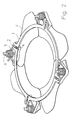
- FIGS. 1 and 2 illustrate the synchronizing ring disk 1 in engagement with a pin 2 on a swivel arm 3 in the closed position and in the open position of the shutter blades 4 .
- the swivel arms 3 are mounted rotatably about swivel pins 5 which are fastened to a circular ring-shaped blade carrier (not illustrated).
- the pins 2 engage in a form-fitting manner in elongated holes 6 which are integrally formed facing radially outwards in the form of a lug on the outer circumference of the synchronizing ring disk 1 .
- the distance between the lugs with the elongated holes 6 corresponds to the distance between the swivel pins 5 on the blade carrier.
- the pins 2 are positioned on the swivel arms 3 in such a manner that the lugs which are integrally formed on the synchronizing ring disk 1 and have the elongated holes 6 are rotated away from the swivel pins 5 by means of the pins 2 during the swiveling of the swivel arms 3 .
- the pins 2 run to and fro in the radial direction in the elongated holes 9 while the synchronizing ring disk 1 is rotated in a reciprocating manner in the bearing surfaces (not illustrated).
Landscapes
- Physics & Mathematics (AREA)
- General Physics & Mathematics (AREA)
- Shutters For Cameras (AREA)
- Operating, Guiding And Securing Of Roll- Type Closing Members (AREA)
Applications Claiming Priority (7)
| Application Number | Priority Date | Filing Date | Title |
|---|---|---|---|
| DE102010005432 | 2010-01-24 | ||
| DE102010005432 | 2010-01-24 | ||
| DE102010005432.1 | 2010-01-24 | ||
| DE102010020638.5A DE102010020638B4 (de) | 2010-01-24 | 2010-05-15 | Vorrichtung zur Synchronisierung von Verschlußlamellen |
| DE102010020638 | 2010-05-15 | ||
| DE102010020638.5 | 2010-05-15 | ||
| PCT/EP2011/000187 WO2011088984A1 (de) | 2010-01-24 | 2011-01-18 | Vorrichtung zur synchronisierung von verschlusslamellen |
Publications (2)
| Publication Number | Publication Date |
|---|---|
| US20120288270A1 US20120288270A1 (en) | 2012-11-15 |
| US8534935B2 true US8534935B2 (en) | 2013-09-17 |
Family
ID=43754682
Family Applications (1)
| Application Number | Title | Priority Date | Filing Date |
|---|---|---|---|
| US13/574,691 Expired - Fee Related US8534935B2 (en) | 2010-01-24 | 2011-01-18 | Device for synchronizing shutter blades |
Country Status (5)
| Country | Link |
|---|---|
| US (1) | US8534935B2 (enExample) |
| EP (1) | EP2526460B1 (enExample) |
| JP (1) | JP2013518293A (enExample) |
| DE (1) | DE102010020638B4 (enExample) |
| WO (1) | WO2011088984A1 (enExample) |
Cited By (1)
| Publication number | Priority date | Publication date | Assignee | Title |
|---|---|---|---|---|
| WO2022046164A1 (en) * | 2020-08-25 | 2022-03-03 | Tao Clean, Llc | Articulating body brush |
Families Citing this family (4)
| Publication number | Priority date | Publication date | Assignee | Title |
|---|---|---|---|---|
| EP2828574B1 (en) * | 2012-03-18 | 2016-12-14 | Robe Lighting, Inc | Beam framing system for an automated luminaire |
| CN104155828B (zh) * | 2014-08-26 | 2017-04-05 | 中国科学院光电技术研究所 | 一种改进型的旋转快门机构 |
| WO2020237578A1 (zh) * | 2019-05-30 | 2020-12-03 | 深圳市大疆创新科技有限公司 | 快门装置及摄影装置 |
| JP7645656B2 (ja) | 2021-02-19 | 2025-03-14 | ニデックプレシジョン株式会社 | 羽根駆動装置及びこれを備えた撮像装置 |
Citations (13)
| Publication number | Priority date | Publication date | Assignee | Title |
|---|---|---|---|---|
| US2269400A (en) | 1940-11-30 | 1942-01-06 | Folmer Graflex Corp | High-speed between-the-lens photographic shutter |
| US2354168A (en) | 1942-05-23 | 1944-07-18 | Aiken Thomas Mcg | Camera |
| DE969694C (de) | 1947-07-12 | 1958-07-03 | Junghans Geb Ag | Objektivverschluss |
| US3075445A (en) | 1958-04-11 | 1963-01-29 | Agfa Ag | Camera shutter assembly |
| US3257921A (en) | 1950-03-03 | 1966-06-28 | Graflex Inc | Between-the-lens shutter |
| US5287140A (en) | 1991-04-30 | 1994-02-15 | Copal Company Limited | Control unit for a program shutter |
| US5953550A (en) * | 1993-08-10 | 1999-09-14 | Canon Kabushiki Kaisha | Shutter device of camera |
| US5970268A (en) * | 1995-07-03 | 1999-10-19 | Canon Kabushiki Kaisha | Shutter device of camera having a light blocking member with a variable starting position |
| US6867932B2 (en) * | 2001-06-25 | 2005-03-15 | Canon Kabushiki Kaisha | Iris type light quantity adjusting device, lens device, and image-taking apparatus |
| US7338221B2 (en) * | 2003-09-12 | 2008-03-04 | Seiko Precision Inc. | Sector drive mechanism |
| US7441966B2 (en) * | 2003-07-30 | 2008-10-28 | Seiko Precision Inc. | Shutter and optical apparatus having the same |
| DE102009020596A1 (de) | 2009-02-05 | 2010-08-19 | Prontor Gmbh | Zentralverschluss für eine fotografische Kamera |
| DE102009020287A1 (de) | 2009-05-07 | 2010-11-18 | Leica Camera Ag | Zentralverschluß |
Family Cites Families (4)
| Publication number | Priority date | Publication date | Assignee | Title |
|---|---|---|---|---|
| JP2002365769A (ja) * | 2001-06-05 | 2002-12-18 | Fuji Photo Film Co Ltd | レンズ付きフイルムユニット |
| JP2007309976A (ja) * | 2006-05-16 | 2007-11-29 | Nikon Corp | 変倍装置及び変倍装置を備える顕微鏡 |
| JP4436850B2 (ja) * | 2007-05-01 | 2010-03-24 | オリンパス株式会社 | 絞り装置 |
| JP2010014814A (ja) * | 2008-07-01 | 2010-01-21 | Panasonic Corp | 絞り装置および撮像装置 |
-
2010
- 2010-05-15 DE DE102010020638.5A patent/DE102010020638B4/de not_active Expired - Fee Related
-
2011
- 2011-01-18 EP EP11701747.5A patent/EP2526460B1/de not_active Not-in-force
- 2011-01-18 JP JP2012549285A patent/JP2013518293A/ja active Pending
- 2011-01-18 WO PCT/EP2011/000187 patent/WO2011088984A1/de not_active Ceased
- 2011-01-18 US US13/574,691 patent/US8534935B2/en not_active Expired - Fee Related
Patent Citations (13)
| Publication number | Priority date | Publication date | Assignee | Title |
|---|---|---|---|---|
| US2269400A (en) | 1940-11-30 | 1942-01-06 | Folmer Graflex Corp | High-speed between-the-lens photographic shutter |
| US2354168A (en) | 1942-05-23 | 1944-07-18 | Aiken Thomas Mcg | Camera |
| DE969694C (de) | 1947-07-12 | 1958-07-03 | Junghans Geb Ag | Objektivverschluss |
| US3257921A (en) | 1950-03-03 | 1966-06-28 | Graflex Inc | Between-the-lens shutter |
| US3075445A (en) | 1958-04-11 | 1963-01-29 | Agfa Ag | Camera shutter assembly |
| US5287140A (en) | 1991-04-30 | 1994-02-15 | Copal Company Limited | Control unit for a program shutter |
| US5953550A (en) * | 1993-08-10 | 1999-09-14 | Canon Kabushiki Kaisha | Shutter device of camera |
| US5970268A (en) * | 1995-07-03 | 1999-10-19 | Canon Kabushiki Kaisha | Shutter device of camera having a light blocking member with a variable starting position |
| US6867932B2 (en) * | 2001-06-25 | 2005-03-15 | Canon Kabushiki Kaisha | Iris type light quantity adjusting device, lens device, and image-taking apparatus |
| US7441966B2 (en) * | 2003-07-30 | 2008-10-28 | Seiko Precision Inc. | Shutter and optical apparatus having the same |
| US7338221B2 (en) * | 2003-09-12 | 2008-03-04 | Seiko Precision Inc. | Sector drive mechanism |
| DE102009020596A1 (de) | 2009-02-05 | 2010-08-19 | Prontor Gmbh | Zentralverschluss für eine fotografische Kamera |
| DE102009020287A1 (de) | 2009-05-07 | 2010-11-18 | Leica Camera Ag | Zentralverschluß |
Cited By (2)
| Publication number | Priority date | Publication date | Assignee | Title |
|---|---|---|---|---|
| WO2022046164A1 (en) * | 2020-08-25 | 2022-03-03 | Tao Clean, Llc | Articulating body brush |
| US11672327B1 (en) | 2020-08-25 | 2023-06-13 | Tao Clean, Llc | Articulating body brush |
Also Published As
| Publication number | Publication date |
|---|---|
| WO2011088984A1 (de) | 2011-07-28 |
| JP2013518293A (ja) | 2013-05-20 |
| DE102010020638A1 (de) | 2011-07-28 |
| EP2526460A1 (de) | 2012-11-28 |
| US20120288270A1 (en) | 2012-11-15 |
| DE102010020638B4 (de) | 2014-05-08 |
| EP2526460B1 (de) | 2014-07-02 |
Similar Documents
| Publication | Publication Date | Title |
|---|---|---|
| US8534935B2 (en) | Device for synchronizing shutter blades | |
| JP5474948B2 (ja) | 被加工物搬送台 | |
| EP3868195A3 (en) | Trimmer head assembly for a trimmer | |
| RU2014110929A (ru) | Ведущий шкив бесступенчатой трансмиссии | |
| CN111571803B (zh) | 用于唇缘的涂层的改进的工具装置 | |
| MX2010007472A (es) | Sistemas de cabo salvavidas, auto-retractil y sistemas de freno para los mismos. | |
| RU2016136981A (ru) | Сиденье транспортного средства (варианты) | |
| WO2009028065A1 (ja) | イオン注入装置、基板クランプ機構、及びイオン注入方法 | |
| KR20160001463U (ko) | 행거 자동 회전 장치 | |
| US20150250093A1 (en) | Scraping device, seed meter and single grain sowing machine | |
| AU2015334473A1 (en) | Fixed line pivoting trimmer heads pivoting concepts | |
| FI3023540T3 (fi) | Segmentoitu roottorin kansikokoonpano | |
| RU2015105267A (ru) | Закрывающее устройство для фиксатора замка транспортного средства | |
| CA2639205A1 (en) | Gage enclosure with cover removal mechanism | |
| JP2013518293A5 (enExample) | ||
| JP2015112699A (ja) | 多軸ねじ締付け装置 | |
| RU2017136107A (ru) | Забойные двигатели с ударным приводом | |
| RU2014146293A (ru) | Устройство изготовления бортового кольца | |
| EP3092436B1 (en) | Stop mechanism for a rotary device | |
| CN105312890B (zh) | 螺母装配工具 | |
| JP5474144B2 (ja) | シートベルト引き込みデバイス | |
| JP2013256707A5 (enExample) | ||
| JP2007309381A5 (enExample) | ||
| CH710993A2 (fr) | Support pour assemblage de mouvements horlogers. | |
| JP7388980B2 (ja) | ブレード取付治具 |
Legal Events
| Date | Code | Title | Description |
|---|---|---|---|
| AS | Assignment |
Owner name: LEICA CAMERA AG, GERMANY Free format text: ASSIGNMENT OF ASSIGNORS INTEREST;ASSIGNOR:AAB, KONSTANTIN;REEL/FRAME:028623/0693 Effective date: 20120710 |
|
| STCF | Information on status: patent grant |
Free format text: PATENTED CASE |
|
| FEPP | Fee payment procedure |
Free format text: PAYOR NUMBER ASSIGNED (ORIGINAL EVENT CODE: ASPN); ENTITY STATUS OF PATENT OWNER: LARGE ENTITY |
|
| FPAY | Fee payment |
Year of fee payment: 4 |
|
| FEPP | Fee payment procedure |
Free format text: MAINTENANCE FEE REMINDER MAILED (ORIGINAL EVENT CODE: REM.); ENTITY STATUS OF PATENT OWNER: LARGE ENTITY |
|
| LAPS | Lapse for failure to pay maintenance fees |
Free format text: PATENT EXPIRED FOR FAILURE TO PAY MAINTENANCE FEES (ORIGINAL EVENT CODE: EXP.); ENTITY STATUS OF PATENT OWNER: LARGE ENTITY |
|
| STCH | Information on status: patent discontinuation |
Free format text: PATENT EXPIRED DUE TO NONPAYMENT OF MAINTENANCE FEES UNDER 37 CFR 1.362 |
|
| FP | Lapsed due to failure to pay maintenance fee |
Effective date: 20210917 |