US8345323B2 - Image reading lens system and image reading apparatus - Google Patents
Image reading lens system and image reading apparatus Download PDFInfo
- Publication number
- US8345323B2 US8345323B2 US12/822,787 US82278710A US8345323B2 US 8345323 B2 US8345323 B2 US 8345323B2 US 82278710 A US82278710 A US 82278710A US 8345323 B2 US8345323 B2 US 8345323B2
- Authority
- US
- United States
- Prior art keywords
- lens
- image reading
- lens system
- image
- object side
- Prior art date
- Legal status (The legal status is an assumption and is not a legal conclusion. Google has not performed a legal analysis and makes no representation as to the accuracy of the status listed.)
- Expired - Fee Related, expires
Links
Images


Classifications
-
- G—PHYSICS
- G02—OPTICS
- G02B—OPTICAL ELEMENTS, SYSTEMS OR APPARATUS
- G02B9/00—Optical objectives characterised both by the number of the components and their arrangements according to their sign, i.e. + or -
- G02B9/60—Optical objectives characterised both by the number of the components and their arrangements according to their sign, i.e. + or - having five components only
-
- G—PHYSICS
- G02—OPTICS
- G02B—OPTICAL ELEMENTS, SYSTEMS OR APPARATUS
- G02B13/00—Optical objectives specially designed for the purposes specified below
- G02B13/24—Optical objectives specially designed for the purposes specified below for reproducing or copying at short object distances
Definitions
- the present invention relates to an image reading apparatus such as an image scanner and an image reading lens system mounted on the image reading apparatus.
- image reading apparatuses such as copiers, facsimiles, and image scanners for reading an original image such as a document or an image and converting the image into digital image data have come into widespread use.
- image reading apparatuses by using an imaging lens system (hereinafter referred to as an image reading lens system), the original image is formed on, for example, a CCD image sensor.
- an imaging lens system hereinafter referred to as an image reading lens system
- various aberrations are suppressed with good balance, and thus a high resolving power is demanded.
- high aperture efficiency is demanded even in the corner of the screen.
- the image reading lens system has been further demanded to be reduced in size and cost. Further, in accordance with an increase in the image reading speed of the image reading apparatus, a faster (smaller F number) image reading lens system is demanded.
- JP-A-9-101452 As the compact image reading lens system, there has been known a telephoto type lens system having four groups and four elements (for example, refer to JP-A-9-101452). Further, as the faster image reading lens system, there has been known a Gauss type lens system having four groups and six elements (for example, refer to JP-A-9-113802). Furthermore, as disclosed in JP-A-2000-241701, there has been an image reading lens system capable of achieving both of an increase in speed and reduction in size by adopting a configuration having five groups and five elements.
- the image reading lens system which has four groups and four elements in JP-A-9-101452 is not able to correct chromatic aberrations sufficiently, and is inappropriate for reading of a color original image. Further, the image reading lens system having this configuration has a problem in that it is difficult to obtain a sufficient resolving power when the lens system is formed as a faster lens system. Further, the image reading lens system which has six groups and four elements in JP-A-9-113802 is formed as a fast lens system, in which it is difficult to make the diameter of the lens small, and thus the system is disadvantageous for compactness. For this reason, configurations for reducing the height of the lens by cutting the upper and lower ends of the lens respectively have also been contrived.
- the invention has been made in view of the above-mentioned problems, and its object is to provide a low-cost, compact, and fast image reading lens system capable of maintaining high aperture efficiency up to the corner of a screen, correcting various aberrations with excellent balance, and having a high resolving power, and to provide an image reading apparatus having the image reading lens system.
- an image reading lens system includes, in order from an object side: a positive first lens of which a convex surface faces toward the object side; a second lens formed as a biconcave lens; a third lens formed as a biconvex lens; a positive fourth lens of which a convex surface faces toward an image side; and a negative fifth lens of which a convex surface faces toward the image side.
- the lens system satisfies the following conditional expressions (1) and (2): 0.06 ⁇ D 8/ f ⁇ 0.16 (1), and 0.77 ⁇ f 4/ f ⁇ 1.81 (2).
- the positive fourth lens of which a convex surface faces toward the image side may be a biconvex lens of which a convex surface faces toward the object side, or may be a lens of which the concave surface or the flat surface faces toward the object side.
- the fourth lens is formed as a biconvex lens, it is more preferable to satisfy the following conditional expressions: “0.06 ⁇ D 8 /f ⁇ 0.14”, and “0.77 ⁇ f 4 /f ⁇ 1.59”.
- the fourth lens is formed as a lens of a concave or flat surface and faces toward the object side, it is further more preferable to satisfy the following conditional expressions: “0.10 ⁇ D 8 /f ⁇ 0.16”, and “1.06 ⁇ f 4 /f ⁇ 1.81”.
- the image reading lens system according to the aspect should satisfy the following conditional expression (3): 1.55 ⁇ ( N 1+ N 3+ N 4)/3 ⁇ 1.74 (3).
- the average of refractive indices of the first, third, and fourth lenses which are positive lenses, that is, “(N 1 +N 3 +N 4 )/3” should satisfy the condition of the expression (3).
- the image reading lens system according to the aspect should satisfy the following conditional expression (4): 13.5 ⁇ ( ⁇ 1+ ⁇ 3+ ⁇ 4)/3 ⁇ ( ⁇ 2+ ⁇ 5)/2 (4).
- the difference between the average of the Abbe numbers of the positive lenses and the average of the Abbe numbers of the negative lenses should satisfy the condition of the expression (4).
- conditional expressions (3) and (4) may be satisfied, but it is more preferable that both of them should be satisfied.
- an image reading apparatus includes the above-mentioned image reading lens system.
- the image reading lens system is able to maintain high aperture efficiency up to the corner of screen, sufficiently correct various aberrations with excellent balance, and thereby obtain a high resolving power while having a low-cost and compact configuration. Further, by using the image reading lens system, it is possible to embody an image reading apparatus capable of increasing the reading speed thereof without lowering the optical performance thereof while achieving compactness.
- FIG. 1 is a sectional view illustrating a configuration of an image reading lens system according to Example 1;
- FIGS. 2A to 2D are aberration diagrams illustrating spherical aberration, astigmatism, distortion, and lateral chromatic aberration of the image reading lens system according to Example 1;
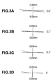
- FIGS. 3A to 3D are aberration diagrams illustrating lateral aberrations of the image reading lens system according to Example 1;
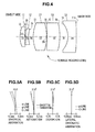
- FIG. 4 is a sectional view illustrating a configuration of an image reading lens system according to Example 2.
- FIGS. 5A to 5D are aberration diagrams illustrating spherical aberration, astigmatism, distortion, and lateral chromatic aberration of the image reading lens system according to Example 2;
- FIGS. 6A to 6D are aberration diagrams illustrating lateral aberrations of the image reading lens system according to Example 2;
- FIG. 7 is a sectional view illustrating a configuration of an image reading lens system according to Example 3.
- FIGS. 8A to 8D are aberration diagrams illustrating spherical aberration, astigmatism, distortion, and lateral chromatic aberration of the image reading lens system according to Example 3;
- FIGS. 9A to 9D are aberration diagrams illustrating lateral aberrations of the image reading lens system according to Example 3.
- FIG. 10 is a sectional view illustrating a configuration of an image reading lens system according to Example 4.
- FIGS. 11A to 11D are aberration diagrams illustrating spherical aberration, astigmatism, distortion, and lateral chromatic aberration of the image reading lens system according to Example 4;
- FIGS. 12A to 12D are aberration diagrams illustrating lateral aberrations of the image reading lens system according to Example 4.
- FIG. 13 is a sectional view illustrating a configuration of an image reading lens system according to Example 5.
- FIGS. 14A to 14D are aberration diagrams illustrating spherical aberration, astigmatism, distortion, and lateral chromatic aberration of the image reading lens system according to Example 5;
- FIGS. 15A to 15D are aberration diagrams illustrating lateral aberrations of the image reading lens system according to Example 5;
- FIG. 16 is a sectional view illustrating a configuration of an image reading lens system according to Example 6;
- FIGS. 17A to 17D are aberration diagrams illustrating spherical aberration, astigmatism, distortion, and lateral chromatic aberration of the image reading lens system according to Example 6;
- FIG. 1 shows an image reading lens system 11 used in an image reading apparatuses.
- the image reading lens system 11 forms images of original documents, which are placed at a predetermined interval so as to be close to the object side, on image sensors which are arranged at a predetermined interval so as to be close to the image side.
- the image reading lens system 11 has a five-group five-element configuration in which first lens L 1 to fifth lens L 5 are arranged in order from the object side.
- the first lens L 1 is a lens which has a positive refractive power and of which a convex surface faces toward the object side.
- the second lens L 2 is formed as a biconcave lens, and the third lens L 3 is formed as a biconvex lens.
- the fourth lens L 4 is formed as a lens which has a positive refractive power and of which a convex surface faces toward the image side.
- the fifth lens L 5 is a lens which has a negative refractive power and of which a convex surface faces toward the image side.
- the fourth lens L 4 When the fourth lens L 4 has a positive refractive power and of which a convex surface faces toward the image side, it may be a biconvex lens of which a convex surface faces toward the object side, may be a plano-convex lens of which the flat surface faces toward the object side, or may be a meniscus lens of which a concave surface faces toward the object side. Furthermore, in the lens configuration of FIG. 1 , the fourth lens L 4 is formed as a biconvex lens.
- the Conditional Expression (1) defines a ratio “D 8 /f” of the space D 8 between the fourth lens L 4 and the fifth lens L 5 to the focal length f of the whole system of the image reading lens system 11 .
- the value of “D 8 /f” is set to be large, this is advantageous for correction of image field curvature and coma aberration.
- the value is more than the upper limit of the Conditional Expression (1), the total length of the image reading lens system 11 increases, and thus it is difficult to achieve compactness.
- the value of “D 8 /f” is set to be small, this is advantageous for compactness of the image reading lens system 11 .
- the value is less than the lower limit of the Conditional Expression (1), it is difficult to correct image field curvature and coma aberration satisfactorily.
- the Conditional Expression (2) is a condition relating to distortion, and defines a ratio “f 4 /f” of the focal length f 4 of the fourth lens L 4 to the focal length f of the whole system of the image reading lens system 11 .
- f 4 /f the value of “f 4 /f” is more than the upper limit of the Conditional Expression (2), distortion increases in the direction of “+”.
- the value is less than the lower limit, the distortion increases in the direction of “ ⁇ ”. Thus, these are not preferable.
- the fourth lens L 4 may be formed as a biconvex lens. In this case, it is more preferable to satisfy the following Conditional Expressions (1a) and (2a). 0.06 ⁇ D 8/ f ⁇ 0.14 (1a) 0.77 ⁇ f 4/ f ⁇ 1.59 (2a)
- the fourth lens L 4 may be formed as a piano-convex lens or a meniscus lens of which a flat surface or a concave surface faces toward the object side. In this case, it is more preferable to satisfy the following Conditional Expressions (1b) and (2b). 0.10 ⁇ D 8/ f ⁇ 0.16 (1b) 1.06 ⁇ f 4/ f ⁇ 1.81 (2b)
- a refractive index of a j-th lens at the e-line (a wavelength of 546.07 nm) is defined as Nj
- an Abbe number of the j-th lens at the d-line (a wavelength of 587.56 nm) is defined as ⁇ j.
- the system may be configured so as to satisfy any one of the Conditional Expressions (3) and (4). However, it is more preferable that the system should be configured to satisfy both of them simultaneously. 1.55 ⁇ ( N 1+ N 3+ N 4)/3 ⁇ 1.74 (3) 13.5 ⁇ ( ⁇ 1+ ⁇ 3+ ⁇ 4)/3 ⁇ ( ⁇ 2+ ⁇ 5)/2 (4)
- the Conditional Expression (4) is a condition relating to longitudinal chromatic aberration, and defines a difference “( ⁇ 1 + ⁇ 3 + ⁇ 4 )/3 ⁇ ( ⁇ 2 + ⁇ 5 )/2” between the average value of the Abbe numbers ⁇ 1 , ⁇ 3 , and ⁇ 4 of the first lens L 1 , the third lens L 3 , and the fourth lens L 4 which are positive lenses and the average value of the Abbe numbers ⁇ 2 and ⁇ 5 of the second lens L 2 and the fifth lens L 5 which are negative lenses.
- the value of “( ⁇ 1 + ⁇ 3 + ⁇ 4 )/3 ⁇ ( ⁇ 2 + ⁇ 5 )/2” is less than the lower limit of the Conditional Expression (4), it is difficult to correct longitudinal chromatic aberration satisfactorily.
- the image side and the object side of the image reading lens system 11 may be reversed.
- the first lens L 1 , the second lens L 2 , the third lens L 3 , the fourth lens L 4 , and the fifth lens L 5 may be arranged.
- the lens system can be used as an image magnification lens.
- the lens surfaces of the lenses L 1 to L 5 may be formed to be aspheric. In this case, by employing the aspheric surface, it is possible to perform more favorable correction.
- Example 1 to 6 of the image reading lens system according to the embodiment of the invention will be described in detail.
- the elements and spaces will be referenced by common reference numerals and signs.
- each surface of the lenses is represented by Si
- the radius of curvature of the lens surface Si is represented by Ri (mm).
- the space between the lens surface Si and the lens surface S(i+1), which are adjacent to each other, on the optical axis, that is, the on-axis surface spacing is represented by Di (mm).
- the refractive index of each lens at the e-line is represented by N
- the Abbe number at the d-line is represented by ⁇ .
- Example 1 is the image reading lens system 11 shown in FIG. 1 .
- the lens system has a five-group five-element configuration in which the first to fifth lenses L 1 to L 5 are arranged.
- the first lens L 1 is formed as a lens which has a positive refractive power and of which a convex surface faces toward the object side.
- the second lens L 2 is formed as a biconcave lens, the third lens L 3 and the fourth lens L 4 are formed as biconvex lenses, and the fifth lens L 5 is formed as a negative lens of which a convex surface faces toward the image side.
- Table 1 shows lens data in Example 1. Further, Table 2 shows the focal length f (mm) of the whole system, the F number, the angle of view 2 ⁇ (°), and the imaging magnification ⁇ of the image reading lens system 11 .
- the focal length f 4 of the fourth lens L 4 according to Example 1 is “40.38 (mm)”.
- the numerical values corresponding to the Conditional Expressions (1) to (4) in Example 1 are set to satisfy the Conditional Expressions (1) to (4) and the Conditional Expressions (1a) and (2a) as shown in Table 3.
- FIGS. 2A to 2D and 3 A to 3 D show various aberrations of the image reading lens system 11 .
- FIG. 2A shows spherical aberration
- FIG. 2B shows astigmatism
- FIG. 2C shows distortion (distortion aberration)
- FIG. 2D shows lateral chromatic aberration.
- the spherical aberration diagram of FIG. 2A the spherical aberration at the e-line is indicated by the solid line
- the aberration at the g-line (a wavelength of 435.84 nm) is indicated by the chain line
- the aberration at the C-line (a wavelength of 656.28 nm) is indicated by the chain double-dashed line.
- the aberration on the sagittal image plane is indicated by the solid line
- the aberration on the tangential image plane is indicated by the dashed line.
- the lateral chromatic aberration diagram of FIG. 2D when the e-line is set as a reference, the aberration at the g-line is indicated by the chain line, and the aberration at the C-line is indicated by the chain double-dashed line.
- FIGS. 3A to 3D show lateral aberrations. Specifically, FIGS. 3A to 3D show lateral aberrations at the e-line when the angle of view is 23.8°, 17.1°, 12.4°, and 0° (on the axis).
- the image reading lens system 12 according to Example 2 shown in FIG. 4 has a five-group five-element configuration in which first lens L 1 to fifth lens L 5 are arranged in order from the object side.
- the first lens L 1 is a lens which has a positive refractive power and of which a convex surface faces toward the object side.
- the second lens L 2 is formed as a biconcave lens, and the third lens L 3 is formed as a biconvex lens.
- the fourth lens L 4 is formed as a positive meniscus lens of which a concave surface faces toward the object side and of which a convex surface faces toward the image side.
- the fifth lens L 5 is a negative lens of which a convex surface faces toward the image side.
- Table 4 shows lens data of the image reading lens system 12 .
- Table 5 shows the focal length f (mm) of the whole system, the F number, the angle of view 2 ⁇ (°), and the imaging magnification ⁇ of the image reading lens system 12 .
- the focal length f 4 of the fourth lens L 4 according to Example 2 is “52.70 (mm)”.
- the numerical values corresponding to the Conditional Expressions (1) to (4) are set to satisfy the Conditional Expressions (1) to (4) as shown in Table 6. Further, the values are also set to satisfy the Conditional Expressions (1b) and (2b).
- FIG. 5A shows spherical aberration of the image reading lens system 12
- FIG. 5B shows astigmatism thereof
- FIG. 5C shows distortion (distortion aberration) thereof
- FIG. 5D shows lateral chromatic aberration thereof
- FIGS. 6A to 6D show lateral aberrations at the e-line when the angle of view is 21.0°, 15.0°, 10.8°, and 0° (on the axis).
- the image reading lens system 13 according to Example 3 shown in FIG. 7 has a five-group five element configuration in which the first lens L 1 to fifth lens L 5 are arranged similarly to Example 2.
- the lens system is different in that the fourth lens L 4 is formed as a positive piano-convex lens of which a flat surface faces toward the object side and of which a convex surface faces toward the image side.
- Table 7 shows lens data of the image reading lens system 13 . Further, Table 8 shows the focal length f (mm) of the whole system, the F number, the angle of view 2 ⁇ (°), and the imaging magnification ⁇ of the image reading lens system 13 .
- the focal length f 4 of the fourth lens L 4 according to Example 3 is “70.42 (mm)”.
- the numerical values corresponding to the Conditional Expressions (1) to (4) are set to satisfy the Conditional Expressions (1) to (4) as shown in Table 9. Further, the values are also set to satisfy the Conditional Expressions (1b) and (2b).
- FIG. 8A shows spherical aberration of the image reading lens system 13
- FIG. 8B shows astigmatism thereof
- FIG. 8C shows distortion (distortion aberration) thereof
- FIG. 8D shows lateral chromatic aberration thereof
- FIGS. 9A to 9D show lateral aberrations at the e-line when the angle of view is 18.3°, 13.0°, 9.4°, and 0° (on the axis).
- the image reading lens system 14 according to Example 4 shown in FIG. 10 has a five-group five element configuration in which the first lens L 1 to fifth lens L 5 are arranged similarly to Example 1.
- the fourth lens L 4 is formed as a biconvex lens.
- Table 10 shows lens data of the image reading lens system 14 . Further, Table 11 shows the focal length f (mm) of the whole system, the F number, the angle of view 2 ⁇ (°), and the imaging magnification ⁇ of the image reading lens system 14 .
- the focal length f 4 of the fourth lens L 4 according to Example 4 is “45.15 (mm)”.
- the image reading lens system 15 according to Example 5 shown in FIG. 13 has a five-group five element configuration in which the first lens L 1 to fifth lens L 5 are arranged similarly to Example 1.
- the fourth lens L 4 is formed as a biconvex lens.
- Table 13 shows lens data of the image reading lens system 15 .
- Table 14 shows the focal length f (mm) of the whole system, the F number, the angle of view 2 ⁇ (°), and the imaging magnification ⁇ of the image reading lens system 15 .
- the focal length f 4 of the fourth lens L 4 according to Example 5 is “52.15 (mm)”.
- the numerical values corresponding to the Conditional Expressions (1) to (4) are set to satisfy the Conditional Expressions (1) to (4) and the Conditional Expressions (1a) and (2a) as shown in Table 15.
- the image reading lens system 16 according to Example 6 shown in FIG. 16 has a five-group five element configuration in which the first lens L 1 to fifth lens L 5 are arranged similarly to Example 1.
- the fourth lens L 4 is formed as a biconvex lens.
Landscapes
- Physics & Mathematics (AREA)
- General Physics & Mathematics (AREA)
- Optics & Photonics (AREA)
- Lenses (AREA)
Applications Claiming Priority (2)
| Application Number | Priority Date | Filing Date | Title |
|---|---|---|---|
| JPP2009-151148 | 2009-06-25 | ||
| JP2009151148A JP5283575B2 (ja) | 2009-06-25 | 2009-06-25 | 画像読取レンズ及び画像読取装置 |
Publications (2)
| Publication Number | Publication Date |
|---|---|
| US20100328730A1 US20100328730A1 (en) | 2010-12-30 |
| US8345323B2 true US8345323B2 (en) | 2013-01-01 |
Family
ID=43380399
Family Applications (1)
| Application Number | Title | Priority Date | Filing Date |
|---|---|---|---|
| US12/822,787 Expired - Fee Related US8345323B2 (en) | 2009-06-25 | 2010-06-24 | Image reading lens system and image reading apparatus |
Country Status (4)
| Country | Link |
|---|---|
| US (1) | US8345323B2 (enExample) |
| JP (1) | JP5283575B2 (enExample) |
| CN (1) | CN201754201U (enExample) |
| TW (1) | TWM399412U (enExample) |
Cited By (6)
| Publication number | Priority date | Publication date | Assignee | Title |
|---|---|---|---|---|
| US9164257B2 (en) | 2013-10-11 | 2015-10-20 | Genius Electronic Optical Co., Ltd. | Mobile device and optical imaging lens thereof |
| US9229193B2 (en) | 2013-09-30 | 2016-01-05 | Genius Electronic Optical Co., Ltd. | Imaging lens, and electronic apparatus including the same |
| US9264594B2 (en) | 2013-10-11 | 2016-02-16 | Genius Electronic Optical Co., Ltd. | Mobile device and optical imaging lens thereof |
| US9279956B2 (en) | 2013-07-10 | 2016-03-08 | Genius Electronic Optical Co., Ltd. | Optical imaging lens and electronic device comprising the same |
| US9316812B2 (en) | 2013-07-03 | 2016-04-19 | Genius Electronic Optical Co., Ltd. | Mobile device and optical imaging lens thereof |
| US9703073B2 (en) | 2014-01-27 | 2017-07-11 | Genius Electronic Optical Co., Ltd. | Imaging lens, and electronic apparatus including the same |
Families Citing this family (11)
| Publication number | Priority date | Publication date | Assignee | Title |
|---|---|---|---|---|
| CN103076665A (zh) | 2011-10-26 | 2013-05-01 | 鸿富锦精密工业(深圳)有限公司 | 取像镜头 |
| JP5910191B2 (ja) * | 2012-03-13 | 2016-04-27 | 株式会社リコー | 画像読取レンズ並びに画像読取装置及び画像形成装置 |
| KR101452084B1 (ko) * | 2013-01-22 | 2014-10-16 | 삼성전기주식회사 | 초소형 광학계 및 이를 구비하는 휴대용 기기 |
| CN103293638B (zh) | 2013-02-06 | 2016-03-23 | 玉晶光电(厦门)有限公司 | 光学成像镜头及应用此镜头的电子装置 |
| JP2015060172A (ja) * | 2013-09-20 | 2015-03-30 | 富士フイルム株式会社 | 撮像レンズおよび撮像レンズを備えた撮像装置 |
| EP3605180B1 (en) * | 2017-04-26 | 2021-11-17 | Kyocera Corporation | Imaging lens |
| CN107121755B (zh) * | 2017-06-19 | 2020-08-21 | 南京华捷艾米软件科技有限公司 | 一种用于3d测量的红外镜头 |
| KR102257745B1 (ko) * | 2017-09-26 | 2021-05-28 | 삼성전기주식회사 | 촬상 광학계 |
| CN111443469B (zh) * | 2020-05-20 | 2025-01-28 | 威海世高光电子有限公司 | 超短物距成像镜头及电子设备 |
| KR102238837B1 (ko) * | 2020-07-23 | 2021-04-09 | 엘지이노텍 주식회사 | 촬상 렌즈 |
| CN112485888B (zh) * | 2020-11-25 | 2022-07-05 | 江西联创电子有限公司 | 光学成像镜头及成像设备 |
Citations (5)
| Publication number | Priority date | Publication date | Assignee | Title |
|---|---|---|---|---|
| US4997265A (en) * | 1988-10-14 | 1991-03-05 | Ricoh Company, Ltd. | Zoom lens for variable power copying apparatus |
| JPH09101452A (ja) | 1995-10-05 | 1997-04-15 | Fuji Photo Optical Co Ltd | 読取用レンズ |
| JPH09113802A (ja) | 1995-10-16 | 1997-05-02 | Ricoh Co Ltd | 読取レンズ |
| JP2000241701A (ja) | 1999-02-23 | 2000-09-08 | Canon Inc | 画像読取用レンズ |
| US7450275B2 (en) * | 2003-06-24 | 2008-11-11 | Ricoh Company, Limited | Document reading lens, document reading lens unit, document reader, and image forming apparatus |
Family Cites Families (6)
| Publication number | Priority date | Publication date | Assignee | Title |
|---|---|---|---|---|
| JPS5695207A (en) * | 1979-12-28 | 1981-08-01 | Nippon Kogaku Kk <Nikon> | Compact wide angle lens |
| JPS61109012A (ja) * | 1984-11-01 | 1986-05-27 | Canon Inc | 小型のズ−ムレンズ |
| JPS61148414A (ja) * | 1984-12-21 | 1986-07-07 | Canon Inc | コンパクトなズ−ムレンズ |
| JPH03181901A (ja) * | 1989-12-12 | 1991-08-07 | Minolta Camera Co Ltd | ズーム光学系 |
| JP2000305015A (ja) * | 1999-04-20 | 2000-11-02 | Nikon Corp | ズームレンズ |
| JP2009086644A (ja) * | 2007-09-12 | 2009-04-23 | Fujinon Corp | 撮像レンズおよび撮像装置 |
-
2009
- 2009-06-25 JP JP2009151148A patent/JP5283575B2/ja not_active Expired - Fee Related
-
2010
- 2010-05-06 TW TW099208409U patent/TWM399412U/zh not_active IP Right Cessation
- 2010-06-08 CN CN2010202249586U patent/CN201754201U/zh not_active Expired - Lifetime
- 2010-06-24 US US12/822,787 patent/US8345323B2/en not_active Expired - Fee Related
Patent Citations (6)
| Publication number | Priority date | Publication date | Assignee | Title |
|---|---|---|---|---|
| US4997265A (en) * | 1988-10-14 | 1991-03-05 | Ricoh Company, Ltd. | Zoom lens for variable power copying apparatus |
| JPH09101452A (ja) | 1995-10-05 | 1997-04-15 | Fuji Photo Optical Co Ltd | 読取用レンズ |
| US5900994A (en) | 1995-10-05 | 1999-05-04 | Fuji Photo Optical Co., Ltd. | Readout lens |
| JPH09113802A (ja) | 1995-10-16 | 1997-05-02 | Ricoh Co Ltd | 読取レンズ |
| JP2000241701A (ja) | 1999-02-23 | 2000-09-08 | Canon Inc | 画像読取用レンズ |
| US7450275B2 (en) * | 2003-06-24 | 2008-11-11 | Ricoh Company, Limited | Document reading lens, document reading lens unit, document reader, and image forming apparatus |
Cited By (6)
| Publication number | Priority date | Publication date | Assignee | Title |
|---|---|---|---|---|
| US9316812B2 (en) | 2013-07-03 | 2016-04-19 | Genius Electronic Optical Co., Ltd. | Mobile device and optical imaging lens thereof |
| US9279956B2 (en) | 2013-07-10 | 2016-03-08 | Genius Electronic Optical Co., Ltd. | Optical imaging lens and electronic device comprising the same |
| US9229193B2 (en) | 2013-09-30 | 2016-01-05 | Genius Electronic Optical Co., Ltd. | Imaging lens, and electronic apparatus including the same |
| US9164257B2 (en) | 2013-10-11 | 2015-10-20 | Genius Electronic Optical Co., Ltd. | Mobile device and optical imaging lens thereof |
| US9264594B2 (en) | 2013-10-11 | 2016-02-16 | Genius Electronic Optical Co., Ltd. | Mobile device and optical imaging lens thereof |
| US9703073B2 (en) | 2014-01-27 | 2017-07-11 | Genius Electronic Optical Co., Ltd. | Imaging lens, and electronic apparatus including the same |
Also Published As
| Publication number | Publication date |
|---|---|
| TWM399412U (en) | 2011-03-01 |
| JP5283575B2 (ja) | 2013-09-04 |
| CN201754201U (zh) | 2011-03-02 |
| US20100328730A1 (en) | 2010-12-30 |
| JP2011008007A (ja) | 2011-01-13 |
Similar Documents
| Publication | Publication Date | Title |
|---|---|---|
| US8345323B2 (en) | Image reading lens system and image reading apparatus | |
| JP5698834B2 (ja) | 撮像レンズおよび撮像装置 | |
| US8767298B2 (en) | Imaging lens | |
| CN201903687U (zh) | 摄像透镜及摄像装置 | |
| JP5680741B2 (ja) | 撮像レンズおよび撮像装置 | |
| JP2006317916A (ja) | 撮像レンズ | |
| JP5571255B2 (ja) | 対物光学系およびこれを用いた内視鏡装置 | |
| US6747810B2 (en) | Single focus lens having short overall length | |
| US7599130B2 (en) | Image reading lens and image reading apparatus | |
| US20150160443A1 (en) | Imaging lens and imaging apparatus | |
| US20030161050A1 (en) | Sigle focus lens | |
| US5920436A (en) | Large-aperture lens for low-illuminance imaging | |
| JP2008116794A (ja) | 撮像レンズ | |
| JP2007218947A (ja) | 画像読取レンズ及び画像読取装置 | |
| JP3720187B2 (ja) | レンズ | |
| US6366412B1 (en) | Lens system for reading images and image reader | |
| JP4699032B2 (ja) | 画像読取用レンズおよび画像読取装置 | |
| JP2000249912A (ja) | 結像レンズおよびこれを用いた画像読取装置 | |
| JP2001100096A (ja) | 4枚画像読取レンズおよびこれを用いた画像読取装置 | |
| US6999246B2 (en) | Image scanning lens and image scanning device that uses same | |
| JP2005316015A (ja) | 撮像レンズ | |
| JP2000249916A (ja) | 結像レンズおよびこれを用いた画像読取装置 | |
| JP3556823B2 (ja) | レンズ | |
| JP2005234068A (ja) | 画像読取用レンズおよび画像読取装置 | |
| JP2002031753A (ja) | 4枚画像読取レンズおよびこれを用いた画像読取装置 |
Legal Events
| Date | Code | Title | Description |
|---|---|---|---|
| AS | Assignment |
Owner name: FUJINON CORPORATION, JAPAN Free format text: ASSIGNMENT OF ASSIGNORS INTEREST;ASSIGNOR:OTOMO, RYOKO;REEL/FRAME:024609/0237 Effective date: 20100616 |
|
| AS | Assignment |
Owner name: FUJIFILM CORPORATION, JAPAN Free format text: MERGER;ASSIGNOR:FUJINON CORPORATION;REEL/FRAME:029379/0245 Effective date: 20100701 |
|
| FEPP | Fee payment procedure |
Free format text: PAYOR NUMBER ASSIGNED (ORIGINAL EVENT CODE: ASPN); ENTITY STATUS OF PATENT OWNER: LARGE ENTITY |
|
| REMI | Maintenance fee reminder mailed | ||
| LAPS | Lapse for failure to pay maintenance fees | ||
| STCH | Information on status: patent discontinuation |
Free format text: PATENT EXPIRED DUE TO NONPAYMENT OF MAINTENANCE FEES UNDER 37 CFR 1.362 |
|
| STCH | Information on status: patent discontinuation |
Free format text: PATENT EXPIRED DUE TO NONPAYMENT OF MAINTENANCE FEES UNDER 37 CFR 1.362 |
|
| FP | Lapsed due to failure to pay maintenance fee |
Effective date: 20170101 |