US8311621B2 - Device for judging degree of awakening and method for judging degree of awakening - Google Patents
Device for judging degree of awakening and method for judging degree of awakening Download PDFInfo
- Publication number
- US8311621B2 US8311621B2 US12/514,692 US51469207A US8311621B2 US 8311621 B2 US8311621 B2 US 8311621B2 US 51469207 A US51469207 A US 51469207A US 8311621 B2 US8311621 B2 US 8311621B2
- Authority
- US
- United States
- Prior art keywords
- degree
- awakening
- judging
- frequency component
- heartbeat
- Prior art date
- Legal status (The legal status is an assumption and is not a legal conclusion. Google has not performed a legal analysis and makes no representation as to the accuracy of the status listed.)
- Expired - Fee Related, expires
Links
Images


Classifications
-
- G—PHYSICS
- G08—SIGNALLING
- G08B—SIGNALLING OR CALLING SYSTEMS; ORDER TELEGRAPHS; ALARM SYSTEMS
- G08B21/00—Alarms responsive to a single specified undesired or abnormal condition and not otherwise provided for
- G08B21/02—Alarms for ensuring the safety of persons
- G08B21/06—Alarms for ensuring the safety of persons indicating a condition of sleep, e.g. anti-dozing alarms
-
- A—HUMAN NECESSITIES
- A61—MEDICAL OR VETERINARY SCIENCE; HYGIENE
- A61B—DIAGNOSIS; SURGERY; IDENTIFICATION
- A61B5/00—Measuring for diagnostic purposes; Identification of persons
- A61B5/16—Devices for psychotechnics; Testing reaction times ; Devices for evaluating the psychological state
- A61B5/165—Evaluating the state of mind, e.g. depression, anxiety
-
- A—HUMAN NECESSITIES
- A61—MEDICAL OR VETERINARY SCIENCE; HYGIENE
- A61B—DIAGNOSIS; SURGERY; IDENTIFICATION
- A61B5/00—Measuring for diagnostic purposes; Identification of persons
- A61B5/16—Devices for psychotechnics; Testing reaction times ; Devices for evaluating the psychological state
- A61B5/18—Devices for psychotechnics; Testing reaction times ; Devices for evaluating the psychological state for vehicle drivers or machine operators
-
- A—HUMAN NECESSITIES
- A61—MEDICAL OR VETERINARY SCIENCE; HYGIENE
- A61B—DIAGNOSIS; SURGERY; IDENTIFICATION
- A61B5/00—Measuring for diagnostic purposes; Identification of persons
- A61B5/24—Detecting, measuring or recording bioelectric or biomagnetic signals of the body or parts thereof
- A61B5/316—Modalities, i.e. specific diagnostic methods
- A61B5/318—Heart-related electrical modalities, e.g. electrocardiography [ECG]
- A61B5/346—Analysis of electrocardiograms
- A61B5/347—Detecting the frequency distribution of signals
-
- A—HUMAN NECESSITIES
- A61—MEDICAL OR VETERINARY SCIENCE; HYGIENE
- A61B—DIAGNOSIS; SURGERY; IDENTIFICATION
- A61B5/00—Measuring for diagnostic purposes; Identification of persons
- A61B5/40—Detecting, measuring or recording for evaluating the nervous system
- A61B5/4029—Detecting, measuring or recording for evaluating the nervous system for evaluating the peripheral nervous systems
- A61B5/4035—Evaluating the autonomic nervous system
-
- A—HUMAN NECESSITIES
- A61—MEDICAL OR VETERINARY SCIENCE; HYGIENE
- A61B—DIAGNOSIS; SURGERY; IDENTIFICATION
- A61B5/00—Measuring for diagnostic purposes; Identification of persons
- A61B5/48—Other medical applications
- A61B5/4806—Sleep evaluation
- A61B5/4809—Sleep detection, i.e. determining whether a subject is asleep or not
-
- G—PHYSICS
- G08—SIGNALLING
- G08G—TRAFFIC CONTROL SYSTEMS
- G08G1/00—Traffic control systems for road vehicles
- G08G1/16—Anti-collision systems
-
- A—HUMAN NECESSITIES
- A61—MEDICAL OR VETERINARY SCIENCE; HYGIENE
- A61B—DIAGNOSIS; SURGERY; IDENTIFICATION
- A61B5/00—Measuring for diagnostic purposes; Identification of persons
- A61B5/02—Detecting, measuring or recording pulse, heart rate, blood pressure or blood flow; Combined pulse/heart-rate/blood pressure determination; Evaluating a cardiovascular condition not otherwise provided for, e.g. using combinations of techniques provided for in this group with electrocardiography or electroauscultation; Heart catheters for measuring blood pressure
- A61B5/024—Detecting, measuring or recording pulse rate or heart rate
-
- A—HUMAN NECESSITIES
- A61—MEDICAL OR VETERINARY SCIENCE; HYGIENE
- A61B—DIAGNOSIS; SURGERY; IDENTIFICATION
- A61B5/00—Measuring for diagnostic purposes; Identification of persons
- A61B5/24—Detecting, measuring or recording bioelectric or biomagnetic signals of the body or parts thereof
- A61B5/316—Modalities, i.e. specific diagnostic methods
- A61B5/318—Heart-related electrical modalities, e.g. electrocardiography [ECG]
- A61B5/346—Analysis of electrocardiograms
- A61B5/349—Detecting specific parameters of the electrocardiograph cycle
- A61B5/352—Detecting R peaks, e.g. for synchronising diagnostic apparatus; Estimating R-R interval
-
- A—HUMAN NECESSITIES
- A61—MEDICAL OR VETERINARY SCIENCE; HYGIENE
- A61B—DIAGNOSIS; SURGERY; IDENTIFICATION
- A61B5/00—Measuring for diagnostic purposes; Identification of persons
- A61B5/72—Signal processing specially adapted for physiological signals or for diagnostic purposes
- A61B5/7235—Details of waveform analysis
- A61B5/7253—Details of waveform analysis characterised by using transforms
- A61B5/7257—Details of waveform analysis characterised by using transforms using Fourier transforms
-
- B—PERFORMING OPERATIONS; TRANSPORTING
- B60—VEHICLES IN GENERAL
- B60K—ARRANGEMENT OR MOUNTING OF PROPULSION UNITS OR OF TRANSMISSIONS IN VEHICLES; ARRANGEMENT OR MOUNTING OF PLURAL DIVERSE PRIME-MOVERS IN VEHICLES; AUXILIARY DRIVES FOR VEHICLES; INSTRUMENTATION OR DASHBOARDS FOR VEHICLES; ARRANGEMENTS IN CONNECTION WITH COOLING, AIR INTAKE, GAS EXHAUST OR FUEL SUPPLY OF PROPULSION UNITS IN VEHICLES
- B60K28/00—Safety devices for propulsion-unit control, specially adapted for, or arranged in, vehicles, e.g. preventing fuel supply or ignition in the event of potentially dangerous conditions
- B60K28/02—Safety devices for propulsion-unit control, specially adapted for, or arranged in, vehicles, e.g. preventing fuel supply or ignition in the event of potentially dangerous conditions responsive to conditions relating to the driver
- B60K28/06—Safety devices for propulsion-unit control, specially adapted for, or arranged in, vehicles, e.g. preventing fuel supply or ignition in the event of potentially dangerous conditions responsive to conditions relating to the driver responsive to incapacity of driver
Definitions
- the present invention relates to a device for judging a degree of awakening and a method for judging a degree of awakening.
- Patent Document 1 discloses a technique which captures an image of an eyeball part of a person, extracts a pupil area of the eyeball part from the captured image, and judges that the degree of awakening is lowered when the time and frequency of blinks are found to be not less than predetermined values according to changes in the extracted shape of the pupil (Patent Document 1: Japanese Patent Application Laid-Open No. 6-270711).
- the device for judging a degree of awakening in accordance with the present invention comprises signal acquiring means for acquiring a biological signal of a person in action, index acquiring means for acquiring a physiological index indicating a strength of a state of acting against sleepiness from the biological signal acquired by the signal acquiring means, and judging means for judging the degree of awakening of the person according to the physiological index acquired by the index acquiring means.
- the method for judging a degree of awakening in accordance with the present invention comprises a signal acquiring step of acquiring a biological signal of a person in action, an index acquiring step of acquiring a physiological index indicating a strength of a state of acting against sleepiness from the biological signal acquired by the signal acquiring step, and a judging step of judging the degree of awakening of the person according to the physiological index acquired by the index acquiring step.
- the device or method for judging a degree of awakening in accordance with the present invention acquires a physiological index indicating a strength of a state of acting against sleepiness from a biological signal of a person in action and judges the degree of awakening according to the physiological index, thereby making it possible to detect weak sleepiness (lowering of the degree of awakening) of the person in action more reliably.
- the device and method for judging a degree of awakening in accordance with the present invention use one correlated with a sympathetic activity.
- the state of acting against sleepiness is a state where a stress acts on the person in action, thereby energizing the activity of the sympathetic nerve system.
- the physiological index for judging the degree of awakening one correlated with the sympathetic activity is used in the device or method for judging a degree of awakening in accordance with the present invention, whereby the state of the sympathetic nerve system, i.e., the state of acting against sleepiness, can be detected more reliably.
- a heartbeat signal is used as the biological signal, and an amplitude spectral power of a heartbeat fluctuation low frequency component acquired from the heartbeat signal is used as the physiological index.
- the amplitude spectral power of a heartbeat fluctuation low frequency component acquired from a heartbeat signal is correlated with the sympathetic activity
- using the amplitude spectral power of a heartbeat fluctuation low frequency component as a physiological index for judging the degree of awakening can appropriately detect the state of the sympathetic activity, i.e., the state of acting against sleepiness.
- the judging means judges that the degree of awakening is lowered when the amplitude spectral power of the heartbeat fluctuation low frequency component is greater than a predetermined value.
- the judging step judges that the degree of awakening is lowered when the amplitude spectral power of the heartbeat fluctuation low frequency component is greater than a predetermined value.
- the amplitude spectral power of the heartbeat fluctuation low frequency component is correlated with the sympathetic activity, and its magnitude is correlated with the briskness of the sympathetic activity, i.e., the degree of acting against sleepiness. Therefore, as the degree of awakening decreases, so that the degree of acting against sleepiness becomes greater, the sympathetic activity becomes brisker, thereby increasing the amplitude spectral power of the heartbeat fluctuation low frequency component.
- the device or method for judging a degree of awakening in accordance with the present invention judges that the degree of awakening is lowered when the amplitude spectral power of the heartbeat fluctuation low frequency component is greater than a predetermined value, thereby making it possible to reliably detect a state where the degree of awakening is lowered while preventing erroneous detections from occurring.
- the judging means judges that the degree of awakening is lowered more when the amplitude spectral power of the heartbeat fluctuation low frequency component is greater than when smaller.
- the judging step judges that the degree of awakening is lowered more when the amplitude spectral power of the heartbeat fluctuation low frequency component is greater than when smaller.
- the device or method for judging a degree of awakening in accordance with the present invention judges that the degree of awakening is lowered more when the amplitude spectral power of the heartbeat fluctuation low frequency component is greater than when smaller, and thus can judge the magnitude of lowering in the degree of awakening.
- the device for judging a degree of awakening in accordance with the present invention further comprises stimulus providing means for imparting a stimulus for raising the degree of awakening to the person and timing setting means for setting a timing for providing the stimulus, while the timing setting means sets the timing for providing the stimulus according to the physiological index indicating the strength of the state of acting against the sleepiness.
- the method for judging a degree of awakening in accordance with the present invention further comprises a stimulus providing step of imparting a stimulus for raising the degree of awakening to the person and a timing setting step of setting a timing for providing the stimulus, while the timing setting step sets the timing for providing the stimulus according to the physiological index indicating the strength of the state of acting against the sleepiness.
- an appropriate timing for providing the stimulus for raising the degree of awakening coincides with or is slightly earlier than a timing when the person acting against sleepiness wants a stimulus.
- the timing when the person acting against sleepiness wants a stimulus is correlated with the strength of the state of acting against sleepiness.
- the device or method for judging a degree of awakening in accordance with the present invention sets the timing for providing the stimulus for raising the degree of awakening according to the physiological index indicating the strength of the state of acting against sleepiness and thus can provide the stimulus at an appropriate timing.
- the device for judging a degree of awakening in accordance with the present invention further comprises stimulus providing means for imparting a stimulus for raising the degree of awakening to the person and timing setting means for setting a timing for providing the stimulus, while the timing setting means sets a timing for providing the stimulus before a predetermined time passes after the amplitude spectral power of the heartbeat fluctuation low frequency component exceeds a predetermined value.
- the method for judging a degree of awakening in accordance with the present invention further comprises a stimulus providing step of imparting a stimulus for raising the degree of awakening to the person and a timing setting step of setting a timing for providing the stimulus, while the timing setting step sets the timing for providing the stimulus before a predetermined time passes after the amplitude spectral power of the heartbeat fluctuation low frequency component exceeds a predetermined value.
- the stimulus is provided before a predetermined time passes after the amplitude spectral power of the heartbeat fluctuation low frequency component exceeds a predetermined value, i.e., when the degree of awakening is lowered so that the degree of acting against sleepiness becomes greater, whereby the stimulus can be provided at an appropriate timing.
- the device for judging a degree of awakening in accordance with the present invention further comprises stimulus providing means for imparting a stimulus for raising the degree of awakening to the person and timing setting means for setting a timing for providing the stimulus, while the timing setting means sets the timing for providing the stimulus before the amplitude spectral power of the heartbeat fluctuation low frequency component attains the nearest local minimum after exceeding a predetermined value.
- the method for judging a degree of awakening in accordance with the present invention further comprises a stimulus providing step of imparting a stimulus for raising the degree of awakening to the person and a timing setting step of setting a timing for providing the stimulus, while the timing setting step sets the timing for providing the stimulus before the amplitude spectral power of the heartbeat fluctuation low frequency component attains the nearest local minimum after exceeding a predetermined value.
- the stimulus is provided before the amplitude spectral power of the heartbeat fluctuation low frequency component attains the nearest local minimum after exceeding a predetermined value, i.e., during when the person in action acts against sleepiness, whereby the stimulus can be provided at an appropriate timing.
- the device and method for judging a degree of awakening in accordance with the present invention use one correlated with a sympathetic activity and one correlated with a parasympathetic activity.
- the activity of the sympathetic nerve system is energized in the state of acting against sleepiness.
- the activity of the parasympathetic nerve system usually decreases.
- the activity of the parasympathetic nerve system increases together with the activity of the sympathetic nerve system.
- the device or method for judging a degree of awakening in accordance with the present invention takes account of the physiological index correlated with the parasympathetic activity in addition to the physiological index correlated with the sympathetic activity, and thus can accurately detect the state of truly acting against sleepiness while excluding the above-mentioned exceptional case.
- a heartbeat signal is used as the biological signal, and respective amplitude spectral powers of heartbeat fluctuation high and low frequency components acquired from the heartbeat signal are used as the physiological index.
- the amplitude spectral power of the heartbeat fluctuation high frequency component acquired from the heartbeat signal is correlated with the parasympathetic activity, further using the heartbeat fluctuation high frequency component as the physiological index can exclude the above-mentioned exceptional case.
- the judging means judges whether the degree of awakening is lowered or not when the amplitude spectral power of the heartbeat fluctuation low frequency component is greater than the amplitude spectral power of the heartbeat fluctuation high frequency component.
- the judging step judges whether the degree of awakening is lowered or not when the amplitude spectral power of the heartbeat fluctuation low frequency component is greater than the amplitude spectral power of the heartbeat fluctuation high frequency component.
- the device for judging a degree of awakening in accordance with the present invention further comprises threshold setting means for setting a threshold for judging whether the degree of awakening of the person is lowered or not, and the judging means judges that the degree of awakening of the person is lowered when the amplitude spectral power of the heartbeat fluctuation low frequency component is greater than the threshold.
- the method for judging a degree of awakening in accordance with the present invention further comprises a threshold setting step of setting a threshold for judging whether the degree of awakening of the person is lowered or not, and the judging step judges that the degree of awakening of the person is lowered when the amplitude spectral power of the heartbeat fluctuation low frequency component is greater than the threshold.
- the threshold for judging whether the degree of awakening of the person is lowered or not is changed according to individual differences, changes in physical conditions in the day even in the case of the same person, or the like, for example.
- the threshold setting means or threshold setting step sets the threshold. Then, when the amplitude spectral power of the heartbeat fluctuation low frequency component is greater than the threshold, it is judged that the degree of awakening is lowered.
- sleepiness can be detected according to characteristics of each person, whereby the accuracy in sleepiness detection can be improved.
- the threshold setting means sets the threshold according to the heartbeat signal and the amplitude spectral power of the heartbeat fluctuation low frequency component.
- the threshold setting step sets the threshold according to the heartbeat signal and the amplitude spectral power of the heartbeat fluctuation low frequency component.
- the threshold can conform to physiological characteristics of each person.
- the present invention employs such a structure as to acquire a physiological index indicating a strength of a state of acting against sleepiness from a biological signal of a person in action and judge a degree of awakening according to the physiological index, whereby weak sleepiness of people in action can be detected more reliably.
- FIG. 1 is a block diagram showing an overall structure of the device for judging a degree of awakening in accordance with a first embodiment
- FIG. 2 is a flowchart showing a procedure of processing for detecting lowering of the degree of awakening by the device for judging a degree of awakening in accordance with the first embodiment
- FIG. 3 is a flowchart showing a procedure of heartbeat signal preprocessing in the processing for detecting lowering of the degree of awakening;
- FIG. 4 is a flowchart showing a procedure of feature amount extraction processing in the processing for detecting lowering of the degree of awakening
- FIG. 5 is a diagram showing an example of heartbeat signals
- FIG. 6 is a schematic diagram for explaining binarization processing of the heartbeat signal
- FIG. 7 is a schematic diagram showing a binary signal obtained by binarizing the heartbeat signal
- FIG. 8 is a schematic diagram for explaining processing for calculating a heartbeat period
- FIG. 9 is a schematic diagram for explaining interpolation processing for the heartbeat period
- FIG. 10 is a schematic diagram for explaining FFT processing for the heartbeat period
- FIG. 11 is a schematic diagram for explaining integration of a power spectrum
- FIG. 12 is a chart showing changes in an amplitude spectral power with time
- FIG. 13 is a diagram for explaining a method for detecting sleepiness (method for judging lowering of a degree of awakening);
- FIG. 14 is a diagram for explaining a method for setting a stimulus providing timing
- FIG. 15 is a table showing criteria for judging sensory evaluation levels (sleepiness levels).
- FIG. 16 is a diagram showing an example of sleepiness detection results
- FIG. 17 is a diagram showing another example of sleepiness detection results
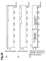
- FIG. 18 is a diagram showing an example of stimulus providing timings
- FIG. 19 is a diagram showing another example of stimulus providing timings
- FIG. 20 is a block diagram showing an overall structure of the device for judging a degree of awakening in accordance with a second embodiment
- FIG. 21 is a flowchart showing a procedure of processing for detecting lowering of the degree of awakening by the device for judging a degree of awakening in accordance with the second embodiment
- FIG. 22 is a flowchart showing a procedure of feature amount extraction processing in the processing for detecting lowering of the degree of awakening
- FIG. 23 is a table showing relationships among the heart rate, low frequency component of a heartbeat fluctuation, and set thresholds;
- FIG. 24 is a diagram showing a method for judging whether or not the heart rate and low frequency component of a heartbeat fluctuation increase/decrease;
- FIG. 25 is a diagram showing an example of sleepiness detection results in a case where a heartbeat fluctuation high frequency component power is not taken into consideration
- FIG. 26 is a diagram showing an example of sleepiness detection results in a case where the heartbeat fluctuation high frequency component power is taken into consideration
- FIG. 27 is a diagram showing sleepiness detection results obtained when a sleepiness judging threshold is fixed.
- FIG. 28 is a diagram showing sleepiness detection results obtained when the sleepiness judging threshold is made variable.
- FIG. 29 is a diagram showing an example of results of changing the sleepiness judging threshold.
- 1 , 2 . . . device for judging a degree of awakening 10 . . . heartbeat sensor; 20 , 20 D . . . ECU; 21 . . . heartbeat signal preprocessing section; 22 , 22 D . . . feature amount extracting section; 23 , 23 D . . . sleepiness detecting section; 24 . . . occurrence of sleepiness informing section; 25 . . . stimulus timing setting section; 26 . . . sleepiness removing stimulus output section; 27 . . . threshold setting section
- FIG. 1 is a block diagram showing the overall structure of the device 1 .
- the device 1 is mounted to a vehicle and detects lowering in the degree of awakening of a driver of the vehicle will be explained by way of example.
- the device 1 is one which detects whether the driver's degree of awakening is lowered or not according to a heartbeat signal obtained from the driver, and presents the result of detection to the driver or provides a stimulus for raising the degree of awakening.
- the device 1 comprises a heartbeat sensor 10 and an electronic control unit (hereinafter referred to as “ECU”) 20 , while a heartbeat signal preprocessing section 21 , a feature amount extracting section 22 , a sleepiness detecting section 23 , an occurrence of sleepiness informing section 24 , a stimulus timing setting section 25 , and a sleepiness removing stimulus output section 26 are constructed in the ECU 20 .
- the heartbeat sensor 10 which is a potentiometric heartbeat sensor for detecting a pulsed voltage (cardiac potential) occurring when cardiac muscle contracts, acquires a heartbeat signal of the driver.
- the heartbeat sensor 10 detects the cardiac potential from an electrode attached to a steering wheel of the vehicle or the like, for example.
- the heartbeat sensor 10 outputs the acquired heartbeat signal to the ECU 20 .
- the heartbeat sensor 10 functions as the biological signal acquiring means recited in the claims and executes the biological signal acquiring step.
- the ECU 20 is constituted by a microprocessor for performing arithmetic operations, a ROM storing programs and the like for causing the microprocessor to execute each processing, a RAM for storing various kinds of data such as results of the arithmetic operations, a backup RAM holding its stored contents with a battery, and the like.
- the heartbeat signal preprocessing section 21 reads the heartbeat signal from the heartbeat sensor 10 at predetermined time intervals, so as to acquire a heartbeat period (RR interval) time series from the heartbeat signal. More specifically, after subjecting the heartbeat signal to a bandpass filtering processing, time series data exceeding a threshold is cut out. Subsequently, thus out-out time series data is binarized, and an interval width (period) is determined by utilizing the binarized data. Then, the interval width is interpolated, so as to determine time series data of the heartbeat period.
- the heartbeat period time series acquired by the heartbeat signal preprocessing section 21 is outputted to the feature amount extracting section 22 .
- the feature amount extracting section 22 acquires an amplitude spectral power (time series) of a heartbeat fluctuation low frequency component which is a physiological index indicating a strength of a state of acting against sleepiness. More specifically, first, the heartbeat period time series data is subjected to FFT processing, so as to acquire an amplitude spectrum which is a heartbeat fluctuation frequency component. Subsequently, a frequency band of a low frequency component is designated for this amplitude spectrum, and the amplitude spectrum of this band is integrated. This processing is performed repeatedly, so as to acquire an amplitude spectral power time series of the heartbeat fluctuation low frequency component.
- the heartbeat signal preprocessing section 21 and the feature amount extracting section 22 function as the index acquiring means recited in the claims and execute the index acquiring step.
- the amplitude spectral power (time series) of the heartbeat fluctuation low frequency component acquired by the feature amount extracting section 22 is outputted to the sleepiness detecting section 23 .
- the sleepiness detecting section 23 judges whether or not sleepiness occurs in the driver (i.e., a degree of awakening of the driver). More specifically, when the amplitude spectral power of the heartbeat fluctuation low frequency component (hereinafter referred to as “heartbeat fluctuation low frequency component power”) is not greater than a first sleepiness judging threshold D 1 , it is judged to be a state without sleepiness.
- the sleepiness detecting section 23 functions as the judging means recited in the claims and executes the judging step.
- Methods for setting the first sleepiness judging threshold D 1 and second sleepiness judging threshold D 2 will now be explained.
- An example is a method which acquires a correlation between sleepiness, which is quantified by another method, and the heartbeat fluctuation low frequency component power.
- a method for quantifying sleepiness is one which evaluates a sleepiness level from a face image (see “Human Sensory Measurement Manual, Vol. 1”, p. 146, Research Institute of Human Engineering for Quality Life).
- the method for setting the first sleepiness judging threshold D 1 and second sleepiness judging threshold D 2 is not limited to this method; they may be set by learning in view of health conditions of the driver such as blood pressure and heart rate.
- a flag indicating a weak sleepiness state is outputted to the occurrence of sleepiness informing section 24 .
- this fact and the heartbeat fluctuation low frequency component power (time series) are outputted to the stimulus timing setting section 25 .
- the occurrence of sleepiness informing section 24 is one which presents awakening degree lowering information to the driver when the flag indicating the weak sleepiness state is fed from the sleepiness detecting section 23 .
- the occurrence of sleepiness informing section 24 presents the awakening degree lowering information by using a display for showing character information and visual information, a speaker for reproducing sound information, and the like.
- the stimulus timing setting section 25 sets a timing for imparting a stimulus for removing sleepiness to the driver. More specifically, as shown in FIG. 14 , the stimulus timing setting section 25 sets a timing for providing a stimulus before a predetermined time (e.g., 60 sec) passes from a time Ts when the heartbeat fluctuation low frequency component power exceeds a predetermined value Dx (the first sleepiness judging threshold D 1 or second sleepiness judging threshold D 2 ) or before the heartbeat fluctuation low frequency component power attains the nearest local minimum after exceeding the predetermined value (first sleepiness judging threshold D 1 or second sleepiness judging threshold D 2 ) (between times Ts and Tm).
- the stimulus timing setting section 25 functions as the timing setting means recited in the claims and executes the timing setting step. Also, the stimulus timing setting section 25 outputs a sleepiness removing stimulus signal to the sleepiness removing stimulus output section 26 at thus set timing.
- the stimulus providing timing is thus set according to the following reason. It will be preferred if the timing for providing the stimulus coincides with or is slightly earlier than a timing at which a person acting against sleepiness wants a stimulus. Providing the stimulus at the timing when the driver wants a stimulus responds to the driver's demand and thus seems to be highly effective in removing sleepiness.
- the inventor conducted tests and, as a result, has found that the timing Tu at which the driver wants the stimulus is around the time Tm at which the heartbeat fluctuation low frequency component power attains the first local minimum after exceeding the predetermined value (first sleepiness judging threshold D 1 or second sleepiness judging threshold D 2 ) or within about 60 sec after the heartbeat fluctuation low frequency component power exceeds the predetermined value.
- the stimulus providing timing is between the time Ts when the heartbeat fluctuation low frequency component power exceeds the predetermined value and the time Te when the low frequency component power becomes lower than the predetermined value (i.e., during when the driver battles against sleepiness), or at a time Tp when the low frequency component power attains the local minimum (i.e., the sleepiness of the driver is the strongest).
- the stimulus providing timing is set before the predetermined time (e.g., 60 sec) passes from the time Ts when the heartbeat fluctuation low frequency component power exceeds the predetermined value Dx (first sleepiness judging threshold D 1 or second sleepiness judging threshold D 2 ) or before the heartbeat fluctuation low frequency component power attains the nearest local minimum after exceeding the predetermined value (first sleepiness judging threshold D 1 or second sleepiness judging threshold D 2 ) (between the times Ts and Tm).
- the predetermined time e.g. 60 sec
- the sleepiness removing stimulus output section 26 imparts the stimulus for removing sleepiness to the driver.
- the stimulus imparted to the driver include the following stimuli: those by sounds using buzzers, audios, and horns; those by light using meter illumination and room illumination; those perceivable by tactile/thermal senses using vibrators embedded in the steering wheel or seat and air-conditioner winds; and those by scents using spraying of fragrances.
- the sleepiness removing stimulus output section 26 functions as the stimulus providing means recited in the claims and executes the stimulus providing step.
- FIG. 2 is a flowchart showing a procedure of processing for detecting lowering of the degree of awakening by the device for judging a degree of awakening 1 .
- FIGS. 3 and 4 are flowcharts showing procedures of heartbeat signal preprocessing and feature amount extraction processing in the processing for detecting lowering of the degree of awakening.
- a heartbeat signal is read from the heartbeat sensor 10 .
- the heartbeat signal read at step S 100 is preprocessed. The heartbeat signal preprocessing will now be explained with reference to FIG. 3 .
- heartbeat signal time series data is processed by a bandpass filter, whereby a passband component of 0.1 Hz to 30 Hz is extracted from the heartbeat signal time series data.
- FIG. 5 shows results of this processing.
- a wave portion not lower than a threshold TH 0 for detecting a heartbeat timing is cut out from the heartbeat signal time series data. Then, as shown in FIG. 6 , the data is binarized such that timings at which the cut-out wave portion is maximized become 1 while the other timings become 0. Consequently, a series of heartbeat timings are determined as shown in FIG. 7 .
- a time (sec) from each heartbeat timing t 1 to the next heartbeat timing t 2 is determined, and thus determined time (t 2 ⁇ t 1 ) is imparted to each heartbeat timing t 1 , whereby heartbeat period information is obtained.
- step S 206 the heartbeat period information is interpolated, so as to determine a heartbeat period curve C, thereby acquiring heartbeat period time series data. Thereafter, the processing shifts to step S 104 shown in FIG. 2 .
- step S 104 feature amount extraction processing for acquiring a heartbeat fluctuation low frequency component power (time series) from the heartbeat period time series data acquired at step S 206 is executed.
- the feature amount extraction processing will now be explained with reference to FIG. 4 .
- step S 300 the heartbeat period time series data in an analysis unit interval width Tterm (sec) prior to a reference time T which is a given timestamp is subjected to fast Fourier transform (FFT) processing as shown in FIG. 10 .
- FFT fast Fourier transform
- an amplitude spectrum is integrated in a frequency band of a low frequency component (around 0.1 Hz) in the power spectrum obtained for each analysis unit interval by the FET processing.
- step S 304 processing of subjecting the heartbeat period time series data in the analysis unit interval width Tterm to the FET processing and integrating the resulting power spectrum is repeated at each reference time after the lapse of a predetermined time. Consequently, as shown in FIG. 12 , time series data of the amplitude spectral power in the frequency band of the lower frequency component is acquired. This time series data of the amplitude spectral power is a heartbeat fluctuation low frequency component power (time series). Thereafter, the processing shifts to step S 106 shown in FIG. 2 .
- step S 106 it is judged whether or not the heartbeat fluctuation low frequency component power is greater than 0 and not greater than the first sleepiness judging threshold D 1 (see FIG. 13 ).
- the heartbeat fluctuation low frequency component power is not greater than the first sleepiness judging threshold D 1 here, it is judged to be a state without sleepiness, whereby this processing is once broken.
- the processing shifts to step S 108 .
- step S 108 it is judged whether the heartbeat fluctuation low frequency component power is greater than the second sleepiness judging threshold D 2 or not (see FIG. 13 ).
- the heartbeat fluctuation low frequency component power is not greater than the second sleepiness judging threshold D 2 here, it is judged to be a state with weak sleepiness (state where the degree of awakening is lowered slightly), whereby the processing shifts to step S 110 .
- the heartbeat fluctuation low frequency component power HRVL is greater than the second sleepiness judging threshold D 2 , on the other hand, it is judged to be a state with strong sleepiness (state where the degree of awakening is lowered greatly), whereby the processing shifts to step S 112 .
- the awakening degree lowering information is presented to the driver at step S 110 .
- the awakening degree lowering information is presented by showing character information or visual information indicating that the degree of awakening is lowered or outputting sound information indicating that the degree of awakening is lowered from a speaker, for example. Thereafter, this processing is once broken.
- a timing for imparting a stimulus for removing sleepiness to the driver is set at step S 112 according to the heartbeat fluctuation low frequency component power (time series). More specifically, the stimulus providing timing is set before a predetermined time (e.g., 60 sec) passes from a time Ts when the heartbeat fluctuation low frequency component power exceeds the second sleepiness judging threshold D 2 . Alternatively, the stimulus providing timing is set before the heartbeat fluctuation low frequency component power attains the nearest local minimum after exceeding the second sleepiness judging threshold D 2 (between times Ts and Tm) (see FIG. 14 ).
- a predetermined time e.g. 60 sec
- the stimulus providing timing is set before the heartbeat fluctuation low frequency component power attains the nearest local minimum after exceeding the second sleepiness judging threshold D 2 (between times Ts and Tm) (see FIG. 14 ).
- a sleepiness removing stimulus signal is outputted according to the timing set at step S 112 , whereby the stimulus for removing sleepiness is imparted to the driver.
- a stimulus by a sound using a buzzer, audio, or horn a stimulus by light using meter illumination or room illumination; a stimulus perceivable by tactile/thermal senses using a vibrator embedded in the steering wheel or seat or an air-conditioner wind; a stimulus by a scent using spraying of a fragrance; or the like is imparted to the driver, so as to remove sleepiness.
- This embodiment acquires a heartbeat fluctuation low frequency component power, which is a physiological index indicating a strength of a state of acting against sleepiness, from a heartbeat signal of the driver and judges the degree of awakening from the heartbeat fluctuation low frequency component power, thereby making it possible to more reliably detect weak sleepiness (lowering of the degree of awakening) of the driver during driving.
- the state of battling against sleepiness is a state where a stress acts on the driver. Therefore, the activity of the sympathetic nerve system of the driver is energized in such a state.
- the heartbeat fluctuation low frequency component power correlated with the sympathetic activity is used in this embodiment, whereby the state of the sympathetic activity, i.e., the state of battling against sleepiness, can be detected more reliably.
- the heartbeat fluctuation low frequency component power is correlated with the sympathetic activity, and its magnitude is correlated with the briskness of the sympathetic activity, i.e., the degree of acting against sleepiness. Therefore, as the degree of awakening decreases, so that the degree of acting against sleepiness becomes greater, the sympathetic nerve becomes brisker, thereby increasing the heartbeat fluctuation low frequency component power.
- This embodiment judges that the degree of awakening is lowered when the heartbeat fluctuation low frequency component power is greater than the first sleepiness judging threshold D 1 , thereby making it possible to reliably detect a state where the degree of awakening is lowered while preventing erroneous detections from occurring.
- This embodiment judges that the degree of awakening is lowered more (sleepiness is stronger) when the heartbeat fluctuation low frequency component power is greater than the second sleepiness judging threshold D 2 , thereby making it possible to judge the strength of sleepiness.
- This embodiment can detect lowering of the degree of awakening of the driver in an early stage, thereby making it possible to evade drowsy driving.
- an appropriate timing for providing the stimulus for removing sleepiness coincides with or is slightly earlier than a timing when the driver battling against sleepiness wants a stimulus.
- the timing when the driver battling against sleepiness wants a stimulus is correlated with the strength of the state of acting against sleepiness.
- This embodiment sets the timing for providing the stimulus according to the heartbeat fluctuation low frequency component power, which is a physiological index indicating the strength of the state of acting against sleepiness, and thus can provide the stimulus at an appropriate timing.
- This embodiment provides the stimulus before a predetermined time (e.g., 60 sec) passes after the heartbeat fluctuation low frequency component power exceeds the second sleepiness judging threshold D 2 , i.e., when the degree of awakening is lowered so that the degree of acting against sleepiness becomes greater, whereby the stimulus can be provided at an appropriate timing.
- a predetermined time e.g. 60 sec
- this embodiment provides the stimulus before the heartbeat fluctuation low frequency component power attains the nearest local minimum after exceeding the second sleepiness judging threshold D 2 , i.e., when the driver battles against sleepiness (acts against sleepiness), whereby the stimulus can be provided at an appropriate timing.
- FIG. 16 shows the results of the test for detecting lowering of the degree of awakening.
- the abscissa indicates the lapse of time (sec)
- the upper part (A) shows the sleepiness level by the sensory evaluation
- the lower part (B) shows the results of sleepiness detection by the device for judging a degree of awakening 1 according to the heartbeat fluctuation low frequency component power.
- areas I, II, and III in FIG. 16 are those judged by the sensory evaluation to be no sleepiness, somewhat sleepy, and sleepy, respectively.
- a degree of awakening 1 is areas judged by the device for judging a degree of awakening 1 to be those with no sleepiness (0 ⁇ heartbeat fluctuation low frequency component power ⁇ first sleepiness judging threshold D 1 ), weak sleepiness (first sleepiness judging threshold D 1 ⁇ heartbeat fluctuation low frequency component power ⁇ second sleepiness judging threshold D 2 ), and strong weakness (heartbeat fluctuation low frequency component power>second sleepiness judging threshold D 2 ), respectively.
- the sleepiness level by the sensory evaluation is level D 1 (somewhat sleepy), it is judged to be weak sleepiness by the device for judging a degree of awakening 1 .
- the sleepiness level by the sensory evaluation is level D 2 (sleepy), it is judged to be strong sleepiness by the device 1 .
- the device 1 succeeded in detecting sleepiness of the subject, whereby the effectiveness of the device 1 has been verified.
- Example 1 A test for detecting lowering of awakening was carried out for a subject different from that of Example 1.
- the test method is the same as that of Example 1 mentioned above and thus will not be explained here.
- FIG. 17 shows the results of the test for detecting lowering of the degree of awakening.
- the sleepiness level by the sensory evaluation is level D 1 (somewhat sleepy)
- the sleepiness level by the sensory evaluation is level D 2 (sleepy)
- the device 1 succeeded in detecting sleepiness of the subject, whereby the effectiveness of the device 1 has been verified.
- FIG. 18 shows the results of the stimulus providing timing test.
- the abscissa of FIG. 18 indicates the lapse of time (sec), while the ordinate indicates the heartbeat fluctuation low frequency component power.
- An arrow shows a timing at which the subject wants the stimulus.
- Example 3 A stimulus providing test was carried out for a subject different from that of Example 3.
- the test method is the same as that of Example 3 mentioned above and thus will not be explained here.
- FIG. 19 shows the results of the stimulus providing timing test.
- the timing at which the subject wanted the stimulus occurred before a predetermined time (60 sec) passed after the heartbeat fluctuation low frequency component power exceeded the second sleepiness judging threshold D 2 and before the heartbeat fluctuation low frequency component power attained the nearest local minimum value after exceeding the second sleepiness judging threshold D 2 , whereby it has been verified that the stimulus providing timing set by the device for judging a degree of awakening 1 is appropriate.
- FIG. 20 is a block diagram showing the overall structure of the device 2 .
- constituents identical or equivalent to those in the first embodiment will be referred to with the same numerals or letters.
- the device for judging a degree of awakening 2 differs from the first embodiment in that it is equipped with an ECU 20 D instead of the above-mentioned ECU 20 . More specifically, the ECU 20 D differs from the ECU 20 in that it includes a feature amount extracting section 22 D and a sleepiness detecting section 23 D instead of the feature amount extracting section 22 and sleepiness detecting section 23 constituting the ECU 20 . The ECU 20 D also differs from the ECU 20 in that it further comprises a threshold setting section 27 for setting a threshold for judging whether or not sleepiness occurs in the driver.
- the structures of the remaining constituents are identical or similar to those of the above-mentioned first embodiment and thus will not be explained here.
- the feature amount extracting section 22 D differs from the feature amount extracting section 22 in that it acquires a spectral power (time series) of a heartbeat fluctuation high frequency component in addition to the heartbeat fluctuation low frequency component power (time series) from the heartbeat period time series acquired by the heartbeat signal preprocessing section 21 . More specifically, first, the feature amount extracting section 22 D subjects the time series data of the heartbeat period to FFT processing, so as to acquire an amplitude spectrum which is a heartbeat fluctuation frequency component. Subsequently, a frequency band of a high frequency component is designated for this amplitude spectrum, and the amplitude spectrum of this band is integrated. This processing is performed repeatedly, so as to acquire an amplitude spectral power time series of the heartbeat fluctuation high frequency component. The method for acquiring the heartbeat fluctuation low frequency component power time series is the same as that mentioned above and thus will not be explained here.
- the heartbeat signal preprocessing section 21 and the feature amount extracting section 22 D also function as the index acquiring means recited in the claims and execute the index acquiring step.
- the heartbeat fluctuation low frequency component power acquired by the feature amount extracting section 22 D is outputted to the threshold setting section 27 .
- the heartbeat fluctuation low frequency component power (time series) and heartbeat fluctuation high frequency component power (time series) are outputted to the sleepiness detecting section 23 D.
- the threshold setting section 27 sets a threshold for judging whether or not sleepiness occurs in the driver.
- the threshold setting section 27 functions as the threshold setting means recited in the claims.
- the threshold set by the threshold setting section 27 is outputted to the sleepiness detecting section 23 D.
- a method for setting a threshold will now be explained with reference to a case of setting the second sleepiness judging threshold D 2 , by way of example.
- the method for setting the first sleepiness judging threshold D 1 is identical or similar to that for the second sleepiness judging threshold D 1 and thus will not be explained here.
- Examples of the method for setting the second sleepiness judging threshold D 2 include those switching a plurality of preset thresholds according to changing states of the heart rate (RR interval) and changing states of the heartbeat fluctuation low frequency component power, and those based on arithmetic operations.
- FIG. 23 is a table showing relationships among the heart rate, low frequency component of a heartbeat fluctuation, and set thresholds.
- four preset thresholds D 2 A, D 2 B, D 2 C, and D 2 D are switched according to changing states of the heart rate and changing states of the heartbeat fluctuation low frequency component power.
- the threshold D 2 A is selected in the state (1) where the heart rate increases or decreases while the heartbeat fluctuation low frequency component power increases.
- the threshold D 213 is selected in the state (2) where the heart rate increases or decreases while the heartbeat fluctuation low frequency component power is unchanged or decreases.
- the threshold D 2 C is selected in the state (3) where the heart rate is unchanged while the heartbeat fluctuation low frequency component power increases.
- the threshold D 2 D is selected in the state (4) where the heart rate does not change while the heartbeat fluctuation low frequency component power is unchanged or decreases.
- the four thresholds D 2 A, D 2 B, D 2 C, and D 2 D have relationships of D 2 A>D 2 C>D 2 B>D 2 D.
- a method for judging whether the heart rate and heartbeat fluctuation low frequency component power increase or decrease will now be explained. Examples of the method for judging whether the heart rate and heartbeat fluctuation low frequency component power increase or decrease include those based on statistical tests and those judging from the gradient of the interval data time series.
- the abscissa of FIG. 24 indicates the time t (sec) passed from a detection start time, while the ordinate indicates the heart rate or heartbeat fluctuation low frequency component power.
- t 0 is a sleepiness detection start time
- ts is a given time for defining an interval 1 .
- tn is the present time
- tb is a given time for defining intervals 2 and 3 .
- This method compares the intervals shown in FIG. 24 with each other by a statistical test, thereby judging whether or not the heart rate or heartbeat fluctuation low frequency component power increases/decreases.
- combinations of the intervals to be tested include the combination of intervals 1 and 3 , the combination of intervals 2 and 3 , and the like; the test is carried out between the intervals in each combination.
- null hypothesis H 0 A case where data included in both intervals are extracted from groups having the same distribution is taken as a null hypothesis H 0
- alternative hypothesis H 1 a case where data included in both intervals are extracted from groups having different distributions is taken as an alternative hypothesis H 1 .
- null hypothesis H 0 it can be determined that no significant difference exists between both intervals, whereby it is judged that the heart rate or heartbeat fluctuation low frequency component power has no change (no increase/decrease).
- alternative hypothesis H 1 it can be determined that a significant difference exists between both intervals, whereby it is judged that the heart rate or heartbeat fluctuation low frequency component power is increased or decreased.
- This method determines the gradient of the data time series in each interval shown in the above-mentioned FIG. 24 and judges whether or not the heart rate and heartbeat fluctuation low frequency component power increase or decrease from the gradient.
- a simple linear regression calculation or the like can be used, for example.
- a simple linear regression calculation is carried out for the interval 3 , so as to determine a gradient B, and it can be judged that there is an increase or decrease when the absolute value of the gradient B is greater than a gradient threshold ⁇ (
- the gradient threshold ⁇ is a constant which can be set arbitrarily.
- a difference amount judging threshold ⁇ is a constant which is set arbitrarily.
- the sleepiness detecting section 23 D judges whether or not sleepiness occurs in the driver (i.e., the degree of awakening of the driver) according to the heartbeat fluctuation low frequency component power (time series). More specifically, when the heartbeat fluctuation low frequency component power is not greater than the first sleepiness judging threshold D 1 set by the threshold setting section 27 , it is judged to be a state without sleepiness. When the heartbeat fluctuation low frequency component power is greater than the first sleepiness judging threshold D 1 but not greater than the second sleepiness judging threshold D 2 , it is judged to be a state with weak sleepiness (state where the degree of awakening is lowered slightly).
- the sleepiness detecting section 23 D also functions as the judging means recited in the claims and executes the judging step.
- FIG. 21 is a flowchart showing a procedure of processing for detecting lowering of the degree of awakening by the device for judging a degree of awakening 2 .
- This processing which is carried out by the ECU 20 D, is repeatedly executed at a predetermined timing before the power of the ECU 20 D is turned off after being turned on.
- steps S 400 and S 402 are identical to the above-mentioned steps S 100 and S 102 , respectively, their overlapping explanations will be omitted here.
- step S 404 feature amount extraction processing 2 for acquiring a heartbeat fluctuation low frequency component power (time series) and a heartbeat fluctuation high frequency component power (time series) from the heartbeat period time series data is executed.
- the feature amount extraction processing 2 will now be explained with reference to FIG. 22 .
- step S 500 the heartbeat period time series data in an analysis unit interval width Tterm (sec) prior to a reference time T which is a given timestamp is subjected to fast Fourier transform (FFT) processing as in the above-mentioned step S 300 .
- FFT fast Fourier transform
- an amplitude spectrum is integrated in a frequency band of a low frequency component (around 0.1 Hz), and an amplitude spectrum is integrated in a frequency band of a high frequency component (around 0.3 Hz).
- step S 504 processing of subjecting the heartbeat period time series data in the analysis unit interval width Tterm to the FET processing and integrating the resulting power spectrum is repeated at each reference time after the lapse of a predetermined time. Consequently, a heartbeat fluctuation low frequency component power (time series) and a heartbeat fluctuation high frequency component power (time series) are acquired. Thereafter, the processing shifts to step S 406 shown in FIG. 21 .
- a threshold for judging whether or not sleepiness occurs in the driver is set according to the heart rate (RR interval) and the heartbeat fluctuation low frequency component power (time series). Since the method for setting the threshold is as mentioned above, overlapping explanations will be omitted here.
- step S 408 it is judged whether the heartbeat fluctuation low frequency component power is greater than the heartbeat fluctuation high frequency component power or not.
- the processing shifts to step S 410 .
- the heartbeat fluctuation low frequency component power is not greater than the heartbeat fluctuation high frequency component power, on the other hand, it is judged to be an exceptional case, whereby the processing is once broken.
- step S 410 it is judged whether or not the heartbeat fluctuation low frequency component power is greater than 0 and not greater than the first sleepiness judging threshold D 1 set at step S 406 .
- the heartbeat fluctuation low frequency component power is not greater the first sleepiness judging threshold D 1 here, it is judged to be a state without sleepiness, whereby the processing is once broken.
- the processing shifts to step S 412 .
- step S 412 it is judged whether or not the heartbeat fluctuation low frequency component power is greater than the second sleepiness judging threshold D 2 set at step S 406 .
- the heartbeat fluctuation low frequency component power is not greater than the second sleepiness judging threshold D 2 here, it is judged to be a state with weak sleepiness (state where the degree of awakening is lowered slightly), whereby the processing shifts to step S 414 .
- the heartbeat fluctuation low frequency component power HRVL is greater than the second sleepiness judging threshold D 2 , on the other hand, it is judged to be a state with strong sleepiness (state where the degree of awakening is lowered greatly), whereby the processing shifts to step S 416 .
- Steps S 414 , S 416 , and S 418 are identical to steps S 110 , S 112 , and S 114 , respectively, and thus will not be explained here.
- the activity of the sympathetic nerve system is energized in the state of acting against sleepiness.
- the activity of the parasympathetic nerve system usually decreases.
- the activity of the parasympathetic nerve system increases together with the activity of the sympathetic nerve system.
- This embodiment judges whether the degree of awakening is lowered or not when the heartbeat fluctuation low frequency component power, which is a physiological index correlated with the sympathetic activity, is greater than the heartbeat fluctuation high frequency component power, which is a physiological index correlated with the parasympathetic activity, and thus can accurately detect the state of truly acting against sleepiness while excluding the above-mentioned exceptional case.
- the threshold for judging whether the degree of awakening of the person is lowered or not is changed according to individual differences, changes in physical conditions in the day even in the case of the same person, or the like, for example.
- This embodiment sets a threshold according to the heartbeat signal and heartbeat fluctuation low frequency component power, and judges that the degree of awakening is lowered when the heartbeat fluctuation low frequency component power is greater than the threshold. Therefore, the threshold can be set in conformity to physiological characteristics of each driver, whereby the accuracy in sleepiness detection can be improved.
- FIG. 25 is a diagram showing an example of sleepiness detection results in the case where the heartbeat fluctuation high frequency component power was not taken into consideration.
- FIG. 26 is a diagram showing an example of sleepiness detection results in the case where the heartbeat fluctuation high frequency component power was taken into consideration. In each of FIGS.
- the abscissa indicates the lapse of time (sec), while the ordinate indicates (A) sensory evaluation results, (B) sleepiness detection results (estimation results), and (C) heartbeat fluctuation low frequency component power/heartbeat fluctuation high frequency component power in order from the upper side.
- the heartbeat fluctuation high frequency component power is not taken into consideration, i.e., the case where it is judged to be a state with strong sleepiness simply when the heartbeat fluctuation low frequency component power exceeds the second sleepiness judging threshold D 2 , it is judged to be a state with strong sleepiness when the heartbeat fluctuation low frequency component power increases at a lapse of time of about 1500 sec as shown in the middle part of FIG. 25 .
- the heartbeat fluctuation high frequency component power also increases, so that this does not seem to be a state where the degree of awakening of the driver is truly lowered, but an exceptional case where the activity of the parasympathetic nerve system increases together with the activity of the sympathetic nerve system, such as a case where the driver is startled or a change occurs in an environment such as air-conditioning. Therefore, the sensory evaluation shown in the upper part (A) of FIG. 25 does not detect sleepiness. That is, such an exceptional case cannot be excluded when the heartbeat fluctuation high frequency component power is not taken into consideration.
- the heartbeat fluctuation high frequency component power is taken into consideration, i.e., the case where it is judged to be a state with strong sleepiness when the heartbeat fluctuation low frequency component power is greater than the heartbeat fluctuation high frequency component power while the heartbeat fluctuation low frequency component power exceeds the second sleepiness judging threshold D 2 , on the other hand, it is not judged to be a state with sleepiness when the heartbeat fluctuation low frequency component power increases after a lapse of about 1500 sec as shown in the middle part of FIG. 26 .
- the heartbeat fluctuation high frequency component power was able to exclude the exceptional case where the activity of the parasympathetic nerve system increased together with the activity of the sympathetic nerve system, whereby the effectiveness of the present invention has been verified.
- FIG. 27 is a diagram showing an example of sleepiness detection results in the case where the sleepiness judging threshold was fixed.
- FIG. 28 is a diagram showing an example of sleepiness detection results in the case where the sleepiness judging threshold was made variable.
- the abscissa indicates the lapse of time (see)
- the ordinate indicates (A) the degree of sleepiness by the sensory evaluation and (B) heartbeat fluctuation low frequency component in order from the upper side.
- the heartbeat fluctuation low frequency component power is less than the second sleepiness judging threshold D 2 in the case where the sleepiness judging threshold is fixed, whereby it is not judged to be a state with strong sleepiness.
- the sleepiness judging threshold is fixed is hard to flexibly respond to individual differences, changes in physical conditions, and the like in the drivers.
- the sleepiness judging threshold is made variable
- the heartbeat fluctuation low frequency component power exceeds the changed second sleepiness judging threshold D 2 when it is judged by the sensory evaluation that strong sleepiness exists at a lapse of time of about 1600 sec as shown in FIG. 28 (see an arrow in the diagram).
- FIG. 29 is a diagram showing an example of results of changing the sleepiness judging threshold.
- the abscissa indicates the lapse of time (sec)
- the ordinate indicates (A) the heartbeat fluctuation low frequency component power and (B) heart rate in order from the upper side.
- the threshold setting method the above-mentioned method based on the statistical test was used. As a result of testing for the heartbeat fluctuation low frequency component power and heart rate in the intervals 1 and 2 in FIG. 29 , it was judged that no significant difference was found in the heartbeat fluctuation low frequency component power, while a significant difference was found (P ⁇ 0.005) in the heart rate. According to these test results, it was decided to change the sleepiness judging threshold. As the method for setting the sleepiness judging thresholds, the above-mentioned method based on the arithmetic operation was used.
- the coefficient b 3.
- the second sleepiness judging threshold D 2 was changed from 10 ⁇ 10 4 to 4.05 ⁇ 10 4 at the time when the interval 2 ended.
- the sleepiness judging threshold is appropriately changed according to the heartbeat fluctuation low frequency component power and heart rate.
- the present invention can be modified in various ways without being restricted to the above-mentioned embodiments.
- the place for mounting the device for judging a degree of awakening is not limited to vehicles, while the subject for which the lowering of the degree of awakening is carried out is not limited to drivers of vehicles.
- the present invention is applicable to health appliances, medical appliances, and the like.
- the sensor for acquiring the heartbeat signal of the driver not only potentiometric heartbeat sensors, but also infrared heartbeat sensors which detect the infrared reflected light quantity periodically changing in response to heartbeats, sensors for detecting the blood pressure of the driver, and the like can be used.
- the levels of the degree of awakening detected by the device for judging a degree of awakening 1 is classified into three stages in the above-mentioned embodiments, they may be two stages or four or more stages.
- the device and method for judging a degree of awakening are constructed such as to acquire a physiological index indicating a strength of a state of acting against sleepiness from a biological signal of a person in action and judge the degree of awakening according to the physiological index, the present invention can more accurately detect weak sleepiness of the person in action.
Landscapes
- Health & Medical Sciences (AREA)
- Life Sciences & Earth Sciences (AREA)
- Engineering & Computer Science (AREA)
- Physics & Mathematics (AREA)
- Veterinary Medicine (AREA)
- Public Health (AREA)
- General Health & Medical Sciences (AREA)
- Animal Behavior & Ethology (AREA)
- Surgery (AREA)
- Biophysics (AREA)
- Pathology (AREA)
- Biomedical Technology (AREA)
- Heart & Thoracic Surgery (AREA)
- Medical Informatics (AREA)
- Molecular Biology (AREA)
- Psychiatry (AREA)
- Neurology (AREA)
- Social Psychology (AREA)
- Psychology (AREA)
- Hospice & Palliative Care (AREA)
- Educational Technology (AREA)
- Developmental Disabilities (AREA)
- Child & Adolescent Psychology (AREA)
- General Physics & Mathematics (AREA)
- Emergency Management (AREA)
- Business, Economics & Management (AREA)
- Anesthesiology (AREA)
- Neurosurgery (AREA)
- Physiology (AREA)
- Cardiology (AREA)
- Measuring Pulse, Heart Rate, Blood Pressure Or Blood Flow (AREA)
- Measurement Of The Respiration, Hearing Ability, Form, And Blood Characteristics Of Living Organisms (AREA)
- Measurement And Recording Of Electrical Phenomena And Electrical Characteristics Of The Living Body (AREA)
Applications Claiming Priority (5)
| Application Number | Priority Date | Filing Date | Title |
|---|---|---|---|
| JP2006-327379 | 2006-12-04 | ||
| JP2006327379 | 2006-12-04 | ||
| JP2007140975A JP4697185B2 (ja) | 2006-12-04 | 2007-05-28 | 覚醒度判定装置及び覚醒度判定方法 |
| JP2007-140975 | 2007-05-28 | ||
| PCT/JP2007/073742 WO2008069337A1 (ja) | 2006-12-04 | 2007-12-04 | 覚醒度判定装置及び覚醒度判定方法 |
Publications (2)
| Publication Number | Publication Date |
|---|---|
| US20100049066A1 US20100049066A1 (en) | 2010-02-25 |
| US8311621B2 true US8311621B2 (en) | 2012-11-13 |
Family
ID=39492209
Family Applications (1)
| Application Number | Title | Priority Date | Filing Date |
|---|---|---|---|
| US12/514,692 Expired - Fee Related US8311621B2 (en) | 2006-12-04 | 2007-12-04 | Device for judging degree of awakening and method for judging degree of awakening |
Country Status (6)
| Country | Link |
|---|---|
| US (1) | US8311621B2 (ko) |
| EP (1) | EP2092889B1 (ko) |
| JP (1) | JP4697185B2 (ko) |
| KR (1) | KR101384439B1 (ko) |
| CN (1) | CN101547643B (ko) |
| WO (1) | WO2008069337A1 (ko) |
Cited By (3)
| Publication number | Priority date | Publication date | Assignee | Title |
|---|---|---|---|---|
| US20120296226A1 (en) * | 2011-05-17 | 2012-11-22 | Industrial Technology Research Institute | Predictive drowsiness alarm method |
| US9129505B2 (en) | 1995-06-07 | 2015-09-08 | American Vehicular Sciences Llc | Driver fatigue monitoring system and method |
| US11023090B2 (en) | 2014-12-18 | 2021-06-01 | Samsung Electronics Co., Ltd. | Method and smart watch for displaying schedule tags |
Families Citing this family (40)
| Publication number | Priority date | Publication date | Assignee | Title |
|---|---|---|---|---|
| ATE488175T1 (de) * | 2006-09-07 | 2010-12-15 | Telozo Gmbh | Verfahren zur ableitung und auswertung von herz- kreislauf-informationen aus herzstromkurven, insbesondere für telemedizinische anwendungen |
| JP2009039167A (ja) * | 2007-08-06 | 2009-02-26 | Toyota Motor Corp | 眠気判定装置 |
| JP2010134533A (ja) * | 2008-12-02 | 2010-06-17 | Toyota Motor Corp | 眠気検出装置 |
| JP2010131061A (ja) * | 2008-12-02 | 2010-06-17 | Toyota Motor Corp | 眠気検出装置 |
| JP4609539B2 (ja) * | 2008-07-04 | 2011-01-12 | トヨタ自動車株式会社 | 眠気検出装置 |
| WO2010001962A1 (ja) | 2008-07-04 | 2010-01-07 | トヨタ自動車株式会社 | 眠気検出装置 |
| JP5387367B2 (ja) * | 2008-12-01 | 2014-01-15 | 富士通株式会社 | 覚醒度判定装置および覚醒度判定方法 |
| WO2010140241A1 (ja) * | 2009-06-04 | 2010-12-09 | 富士通株式会社 | 覚醒度判定装置、覚醒度判定方法および覚醒度判定プログラム |
| JP5704612B2 (ja) * | 2009-06-08 | 2015-04-22 | 公立大学法人名古屋市立大学 | 眠気判定装置 |
| JP5299915B2 (ja) * | 2009-07-22 | 2013-09-25 | 株式会社最新松本技研 | 覚醒度合検出装置 |
| WO2011046178A1 (ja) * | 2009-10-14 | 2011-04-21 | 株式会社デルタツーリング | 生体状態推定装置、生体状態推定システム及びコンピュータプログラム |
| KR101034886B1 (ko) * | 2009-12-30 | 2011-05-17 | 인제대학교 산학협력단 | 짧은 심장박동 주기의 변화를 이용한 졸음상태 판정 시스템 및 방법 |
| JP5585648B2 (ja) * | 2010-03-23 | 2014-09-10 | アイシン精機株式会社 | 覚醒度判定装置、覚醒度判定方法及びプログラム |
| JP5696501B2 (ja) * | 2011-01-27 | 2015-04-08 | 富士通株式会社 | 覚醒時データ生成装置、覚醒時データ生成方法、覚醒時データ生成プログラム及び覚醒度判定装置 |
| US8766819B2 (en) * | 2011-06-17 | 2014-07-01 | The Boeing Company | Crew allertness monitoring of biowaves |
| TWI478691B (zh) * | 2012-01-06 | 2015-04-01 | Wistron Corp | 睡意偵測方法及其裝置 |
| US9815384B2 (en) | 2012-07-09 | 2017-11-14 | Ts Tech Co., Ltd. | Wakefulness-maintenance apparatus |
| JP6209396B2 (ja) * | 2013-04-17 | 2017-10-04 | 株式会社デルタツーリング | 運転支援装置及びコンピュータプログラム |
| JP6312193B2 (ja) | 2013-10-21 | 2018-04-18 | テイ・エス テック株式会社 | 覚醒装置及びシート |
| JP2016182241A (ja) * | 2015-03-26 | 2016-10-20 | パイオニア株式会社 | 眠気算出装置 |
| US10328852B2 (en) * | 2015-05-12 | 2019-06-25 | University Of North Dakota | Systems and methods to provide feedback to pilot/operator by utilizing integration of navigation and physiological monitoring |
| CN106264449B (zh) * | 2015-06-29 | 2022-01-28 | 松下知识产权经营株式会社 | 人状态推定方法和人状态推定系统 |
| CN106361270B (zh) * | 2015-07-22 | 2021-05-07 | 松下电器(美国)知识产权公司 | 清醒度预测方法和清醒度预测装置 |
| JP6803679B2 (ja) | 2016-04-14 | 2020-12-23 | Joyson Safety Systems Japan株式会社 | バックル及び車載システム |
| JP6641642B2 (ja) * | 2016-08-03 | 2020-02-05 | オムロン株式会社 | 生命徴候検出装置 |
| US10473762B2 (en) * | 2016-08-15 | 2019-11-12 | Microsoft Technology Licensing, Llc | Wireless radio module |
| JP6791707B2 (ja) * | 2016-09-30 | 2020-11-25 | 東芝情報システム株式会社 | 眠気推定装置及び眠気推定プログラム |
| EP3579753A1 (en) | 2017-02-10 | 2019-12-18 | Nestlé Skin Health SA | Systems and methods for itch monitoring and measurement |
| KR102045569B1 (ko) * | 2017-06-08 | 2019-12-02 | 고려대학교 산학협력단 | 조종사 상태의 통합 감시 제어 장치 및 이를 이용한 조종사의 임무 수행 능력 유도 방법 |
| JP6937259B2 (ja) * | 2018-03-19 | 2021-09-22 | フォルシアクラリオン・エレクトロニクス株式会社 | 報知装置および報知方法 |
| CN108280242A (zh) * | 2018-03-27 | 2018-07-13 | 新日(无锡)发展有限公司 | 一种车内音响智能控制方法及装置 |
| WO2019188398A1 (ja) * | 2018-03-30 | 2019-10-03 | ソニーセミコンダクタソリューションズ株式会社 | 情報処理装置、移動装置、および方法、並びにプログラム |
| JP7099037B2 (ja) * | 2018-05-07 | 2022-07-12 | オムロン株式会社 | データ処理装置、モニタリングシステム、覚醒システム、データ処理方法、及びデータ処理プログラム |
| JP2019069207A (ja) * | 2018-12-26 | 2019-05-09 | パイオニア株式会社 | 眠気算出装置 |
| WO2020195168A1 (ja) * | 2019-03-28 | 2020-10-01 | パナソニックIpマネジメント株式会社 | 漫然状態判定装置および漫然状態判定方法 |
| TWI749323B (zh) * | 2019-04-30 | 2021-12-11 | 先進光電科技股份有限公司 | 行動載具輔助系統 |
| CN110135764A (zh) * | 2019-05-29 | 2019-08-16 | 中国人民解放军海军特色医学中心 | 一种船舶操纵人员作业能力测评系统及方法 |
| JP2019205894A (ja) * | 2019-08-08 | 2019-12-05 | パイオニア株式会社 | 眠気算出装置 |
| JP2020171734A (ja) * | 2020-07-01 | 2020-10-22 | パイオニア株式会社 | 眠気算出装置 |
| CN112128932A (zh) * | 2020-08-26 | 2020-12-25 | 青岛海尔空调器有限总公司 | 空调器及其控制方法 |
Citations (17)
| Publication number | Priority date | Publication date | Assignee | Title |
|---|---|---|---|---|
| JPH01131648A (ja) | 1987-11-18 | 1989-05-24 | Nippon Denso Co Ltd | 覚醒度判定装置 |
| JPH04348759A (ja) | 1991-05-28 | 1992-12-03 | Matsushita Electric Works Ltd | 覚醒度モニター装置 |
| JPH06270711A (ja) | 1993-03-17 | 1994-09-27 | Nissan Motor Co Ltd | 覚醒状態検知装置 |
| JPH07231880A (ja) | 1994-02-24 | 1995-09-05 | Sanyo Electric Co Ltd | ストレス評価方法及び装置 |
| JPH08299443A (ja) | 1995-05-12 | 1996-11-19 | Seiko Epson Corp | 居眠り防止装置 |
| JPH11314534A (ja) | 1998-05-06 | 1999-11-16 | Nissan Motor Co Ltd | 車両用注意能力低下防止装置 |
| US6070098A (en) | 1997-01-11 | 2000-05-30 | Circadian Technologies, Inc. | Method of and apparatus for evaluation and mitigation of microsleep events |
| JP2001198113A (ja) | 2000-01-18 | 2001-07-24 | Toyota Central Res & Dev Lab Inc | 疲労度演算装置 |
| US20040243013A1 (en) | 2003-05-27 | 2004-12-02 | Taiji Kawachi | Sleepiness level detection device |
| US20050148894A1 (en) | 2004-01-06 | 2005-07-07 | Misczynski Dale J. | Method and system for contactless evaluation of fatigue of an operator |
| JP2006130046A (ja) | 2004-11-05 | 2006-05-25 | Daikin Ind Ltd | 覚醒度判定装置 |
| JP2006158733A (ja) | 2004-12-08 | 2006-06-22 | Toyota Motor Corp | 覚醒度判定装置及び覚醒度判定方法 |
| JP2006247055A (ja) | 2005-03-09 | 2006-09-21 | Toyota Motor Corp | 覚醒度判定装置 |
| JP2007006970A (ja) | 2005-06-28 | 2007-01-18 | Toyota Motor Corp | 生理・心理状態判定装置、生理・心理状態判定方法、リファレンスデータ生成装置、及びリファレンスデータ生成方法。 |
| JP2007195886A (ja) | 2006-01-30 | 2007-08-09 | Toyota Motor Corp | 車両用シート装置 |
| JP2007229218A (ja) | 2006-03-01 | 2007-09-13 | Toyota Motor Corp | 覚醒度推定装置及びシステム並びに方法 |
| JP2007264785A (ja) | 2006-03-27 | 2007-10-11 | Toyota Motor Corp | 眠気検出装置 |
Family Cites Families (4)
| Publication number | Priority date | Publication date | Assignee | Title |
|---|---|---|---|---|
| LU75977A1 (ko) * | 1976-10-12 | 1978-05-16 | ||
| JPS5750097A (en) * | 1980-09-08 | 1982-03-24 | Nissan Motor | Automotive warning device |
| US5012226A (en) * | 1990-02-23 | 1991-04-30 | Love Samuel D | Safety alertness monitoring system |
| KR100646868B1 (ko) * | 2004-12-29 | 2006-11-23 | 삼성전자주식회사 | 피부전도도와 심박 정보를 이용한 홈 제어시스템 및 그 방법 |
-
2007
- 2007-05-28 JP JP2007140975A patent/JP4697185B2/ja not_active Expired - Fee Related
- 2007-12-04 CN CN2007800446557A patent/CN101547643B/zh not_active Expired - Fee Related
- 2007-12-04 WO PCT/JP2007/073742 patent/WO2008069337A1/ja active Application Filing
- 2007-12-04 US US12/514,692 patent/US8311621B2/en not_active Expired - Fee Related
- 2007-12-04 KR KR1020097005588A patent/KR101384439B1/ko active IP Right Grant
- 2007-12-04 EP EP07850316.6A patent/EP2092889B1/en not_active Not-in-force
Patent Citations (20)
| Publication number | Priority date | Publication date | Assignee | Title |
|---|---|---|---|---|
| JPH01131648A (ja) | 1987-11-18 | 1989-05-24 | Nippon Denso Co Ltd | 覚醒度判定装置 |
| JP2570329B2 (ja) | 1987-11-18 | 1997-01-08 | 日本電装株式会社 | 覚醒度判定装置 |
| JPH04348759A (ja) | 1991-05-28 | 1992-12-03 | Matsushita Electric Works Ltd | 覚醒度モニター装置 |
| JP2505072B2 (ja) | 1991-05-28 | 1996-06-05 | 松下電工株式会社 | 覚醒度モニタ―装置 |
| JPH06270711A (ja) | 1993-03-17 | 1994-09-27 | Nissan Motor Co Ltd | 覚醒状態検知装置 |
| JPH07231880A (ja) | 1994-02-24 | 1995-09-05 | Sanyo Electric Co Ltd | ストレス評価方法及び装置 |
| JPH08299443A (ja) | 1995-05-12 | 1996-11-19 | Seiko Epson Corp | 居眠り防止装置 |
| US6070098A (en) | 1997-01-11 | 2000-05-30 | Circadian Technologies, Inc. | Method of and apparatus for evaluation and mitigation of microsleep events |
| JPH11314534A (ja) | 1998-05-06 | 1999-11-16 | Nissan Motor Co Ltd | 車両用注意能力低下防止装置 |
| JP2001198113A (ja) | 2000-01-18 | 2001-07-24 | Toyota Central Res & Dev Lab Inc | 疲労度演算装置 |
| US20040243013A1 (en) | 2003-05-27 | 2004-12-02 | Taiji Kawachi | Sleepiness level detection device |
| US7206631B2 (en) * | 2003-05-27 | 2007-04-17 | Denso Corporation | Sleepiness level detection device |
| US20050148894A1 (en) | 2004-01-06 | 2005-07-07 | Misczynski Dale J. | Method and system for contactless evaluation of fatigue of an operator |
| JP2006130046A (ja) | 2004-11-05 | 2006-05-25 | Daikin Ind Ltd | 覚醒度判定装置 |
| JP2006158733A (ja) | 2004-12-08 | 2006-06-22 | Toyota Motor Corp | 覚醒度判定装置及び覚醒度判定方法 |
| JP2006247055A (ja) | 2005-03-09 | 2006-09-21 | Toyota Motor Corp | 覚醒度判定装置 |
| JP2007006970A (ja) | 2005-06-28 | 2007-01-18 | Toyota Motor Corp | 生理・心理状態判定装置、生理・心理状態判定方法、リファレンスデータ生成装置、及びリファレンスデータ生成方法。 |
| JP2007195886A (ja) | 2006-01-30 | 2007-08-09 | Toyota Motor Corp | 車両用シート装置 |
| JP2007229218A (ja) | 2006-03-01 | 2007-09-13 | Toyota Motor Corp | 覚醒度推定装置及びシステム並びに方法 |
| JP2007264785A (ja) | 2006-03-27 | 2007-10-11 | Toyota Motor Corp | 眠気検出装置 |
Non-Patent Citations (2)
| Title |
|---|
| International Preliminary Report on Patentability for corresponding international application No. PCT/JP2007/073742; Jun. 18, 2009. |
| Jul. 2, 2012 Search Report issued in European Patent Application No. 07850316.6. |
Cited By (4)
| Publication number | Priority date | Publication date | Assignee | Title |
|---|---|---|---|---|
| US9129505B2 (en) | 1995-06-07 | 2015-09-08 | American Vehicular Sciences Llc | Driver fatigue monitoring system and method |
| US20120296226A1 (en) * | 2011-05-17 | 2012-11-22 | Industrial Technology Research Institute | Predictive drowsiness alarm method |
| US9033892B2 (en) * | 2011-05-17 | 2015-05-19 | Industrial Technology Research Institute | Predictive drowsiness alarm method |
| US11023090B2 (en) | 2014-12-18 | 2021-06-01 | Samsung Electronics Co., Ltd. | Method and smart watch for displaying schedule tags |
Also Published As
| Publication number | Publication date |
|---|---|
| EP2092889A4 (en) | 2012-08-01 |
| CN101547643B (zh) | 2012-02-01 |
| US20100049066A1 (en) | 2010-02-25 |
| KR20090089841A (ko) | 2009-08-24 |
| KR101384439B1 (ko) | 2014-04-14 |
| CN101547643A (zh) | 2009-09-30 |
| JP2008161664A (ja) | 2008-07-17 |
| EP2092889A1 (en) | 2009-08-26 |
| EP2092889B1 (en) | 2019-02-27 |
| WO2008069337A1 (ja) | 2008-06-12 |
| JP4697185B2 (ja) | 2011-06-08 |
Similar Documents
| Publication | Publication Date | Title |
|---|---|---|
| US8311621B2 (en) | Device for judging degree of awakening and method for judging degree of awakening | |
| US8346352B2 (en) | Sleepiness judging device | |
| EP2497670B1 (en) | Method and apparatus for monitoring the alertness of the driver of a vehicle | |
| De Rosario et al. | Controlled inducement and measurement of drowsiness in a driving simulator | |
| KR101078466B1 (ko) | 각성 상태 판정 모델 생성 장치, 각성 상태 판정 장치, 경고 장치, 차량, 각성 상태 판정 모델 생성 방법, 각성 상태 판정 방법, 각성 상태 판정 모델 생성 프로그램을 기록한 컴퓨터 판독 가능 기록매체, 및 각성 상태 판정 프로그램을 기록한 컴퓨터 판독 가능 기록매체 | |
| US8098165B2 (en) | System, apparatus and associated methodology for interactively monitoring and reducing driver drowsiness | |
| KR101023512B1 (ko) | 사람의 상태 검출 장치 | |
| JP4867215B2 (ja) | 生理・心理状態判定装置、生理・心理状態判定方法、リファレンスデータ生成装置、及びリファレンスデータ生成方法。 | |
| JP5007975B2 (ja) | 居眠り検知装置 | |
| JP4910547B2 (ja) | 眠気判定装置及び眠気判定プログラム | |
| US7250029B2 (en) | Human condition evaluation system, computer program, and computer-readable record medium | |
| KR20110017883A (ko) | 졸음 이벤트의 검출을 위한 방법 및 장치 | |
| JP4701694B2 (ja) | 覚醒度判定装置及び覚醒度判定方法 | |
| JP2009022370A (ja) | 人の状態推定装置 | |
| US10596963B2 (en) | Fatigue alarm apparatus and method | |
| KR100718941B1 (ko) | 졸음 경고장치 및 졸음 경고방법 | |
| JP2008073450A (ja) | 人の状態推定装置及び人の状態推定方法 | |
| JP4822796B2 (ja) | 睡眠計及び睡眠状態判定方法 | |
| CN107007292B (zh) | 用于获知疲劳的方法 | |
| Deng et al. | Fatigue detection based on infrared video pupillography | |
| JP2009172292A (ja) | 人の状態推定装置 | |
| JP2006136556A (ja) | 居眠り検出装置及び検出方法 | |
| JPH09262216A (ja) | 集中度推定装置 | |
| KR101932147B1 (ko) | 심전도 신호를 이용한 운전자의 졸음운전 진단 방법 및 장치 | |
| JPH0779937A (ja) | 覚醒度判定装置 |
Legal Events
| Date | Code | Title | Description |
|---|---|---|---|
| AS | Assignment |
Owner name: TOYOTA JIDOSHA KABUSHIKI KAISHA,JAPAN Free format text: ASSIGNMENT OF ASSIGNORS INTEREST;ASSIGNOR:HATAKEYAMA, YOSHIYUKI;REEL/FRAME:022681/0296 Effective date: 20090101 Owner name: TOYOTA JIDOSHA KABUSHIKI KAISHA, JAPAN Free format text: ASSIGNMENT OF ASSIGNORS INTEREST;ASSIGNOR:HATAKEYAMA, YOSHIYUKI;REEL/FRAME:022681/0296 Effective date: 20090101 |
|
| STCF | Information on status: patent grant |
Free format text: PATENTED CASE |
|
| FEPP | Fee payment procedure |
Free format text: PAYOR NUMBER ASSIGNED (ORIGINAL EVENT CODE: ASPN); ENTITY STATUS OF PATENT OWNER: LARGE ENTITY |
|
| FPAY | Fee payment |
Year of fee payment: 4 |
|
| FEPP | Fee payment procedure |
Free format text: MAINTENANCE FEE REMINDER MAILED (ORIGINAL EVENT CODE: REM.); ENTITY STATUS OF PATENT OWNER: LARGE ENTITY |
|
| LAPS | Lapse for failure to pay maintenance fees |
Free format text: PATENT EXPIRED FOR FAILURE TO PAY MAINTENANCE FEES (ORIGINAL EVENT CODE: EXP.); ENTITY STATUS OF PATENT OWNER: LARGE ENTITY |
|
| STCH | Information on status: patent discontinuation |
Free format text: PATENT EXPIRED DUE TO NONPAYMENT OF MAINTENANCE FEES UNDER 37 CFR 1.362 |
|
| FP | Lapsed due to failure to pay maintenance fee |
Effective date: 20201113 |