US8256043B2 - Support element for a cushion cover for seating and lying areas - Google Patents
Support element for a cushion cover for seating and lying areas Download PDFInfo
- Publication number
- US8256043B2 US8256043B2 US12/594,346 US59434607A US8256043B2 US 8256043 B2 US8256043 B2 US 8256043B2 US 59434607 A US59434607 A US 59434607A US 8256043 B2 US8256043 B2 US 8256043B2
- Authority
- US
- United States
- Prior art keywords
- spring
- support
- support element
- bars
- legs
- Prior art date
- Legal status (The legal status is an assumption and is not a legal conclusion. Google has not performed a legal analysis and makes no representation as to the accuracy of the status listed.)
- Active, expires
Links
Images


Classifications
-
- A—HUMAN NECESSITIES
- A47—FURNITURE; DOMESTIC ARTICLES OR APPLIANCES; COFFEE MILLS; SPICE MILLS; SUCTION CLEANERS IN GENERAL
- A47C—CHAIRS; SOFAS; BEDS
- A47C7/00—Parts, details, or accessories of chairs or stools
- A47C7/02—Seat parts
- A47C7/025—Springs not otherwise provided for in A47C7/22 - A47C7/35
- A47C7/027—Springs not otherwise provided for in A47C7/22 - A47C7/35 with elastomeric springs
-
- A—HUMAN NECESSITIES
- A47—FURNITURE; DOMESTIC ARTICLES OR APPLIANCES; COFFEE MILLS; SPICE MILLS; SUCTION CLEANERS IN GENERAL
- A47C—CHAIRS; SOFAS; BEDS
- A47C23/00—Spring mattresses with rigid frame or forming part of the bedstead, e.g. box springs; Divan bases; Slatted bed bases
- A47C23/002—Spring mattresses with rigid frame or forming part of the bedstead, e.g. box springs; Divan bases; Slatted bed bases with separate resilient support elements, e.g. elastomeric springs arranged in a two-dimensional matrix pattern
Definitions
- the invention concerns a support element for a cushion cover for seating and lying areas, preferably for mattresses, comprising a base plate that can be fixed to a base, and at least one spring element formed by a plurality of spring arms and extending upward from the base plate in the direction of the cushion cover, wherein the spring arms each are provided with a substantially U-shaped corrugated spring element on the upper ends thereof, oriented away from the base plate, said corrugated spring element comprising at least two parallel spaced spring legs located on concentric ring tracks and disposed about the central axis of the support element and at least one connecting bar joining the spring legs, one end of the spring leg located on the inner ring track being connected to the corresponding spring arm, and one end of the spring leg located on the outer ring track being connected to the support plate provided for supporting the cushion element.
- the support elements usually also are called spring elements and are known as mattress sub-structures in combination with slatted bed frame sub-structures as well as rigid, plate-shaped sub-structures.
- the described support elements are fixed to these plate-shaped sub-structures or slatted frame sub-structures by way of screw connections or, to provide for easier replacement of the support elements, by way of easily loosening fastening techniques, such as quarter-turn fasteners with the base plate having suitable openings.
- the support elements are disposed in regular intervals so that a top view of such a design shows a substantially closed support face comprised of the individual support plates that are part of each support element.
- a top view of such a design shows a substantially closed support face comprised of the individual support plates that are part of each support element.
- the state of the art already includes support elements in which the spring effect of the spring elements is modified by using corresponding auxiliary components that are inserted into the support elements.
- the individual spring arms that are responsible for the spring effect of the spring elements can be limited by using auxiliary components with designs being known in which a plastic component with multiple support arms is disposed between the base plate and sub-structure.
- the plastic component is rotatable about the perpendicular support element central axis in relation to the support element so that the support arms may rest on the individual spring arms in order to stiffen the overall spring effect of the spring element.
- the contact overall results in a stiffening of the spring arm cross-section so that the deflection of the spring element comprised of the spring arms overall is lower with identical load.
- lumbar support adjustments are customary in which stiffening elements between the base plate and the support plate above it are placed on the inside of the support element, said stiffening elements affecting the spring effect of the original spring element.
- the structure of such auxiliary elements is largely determined by the design of the basic spring elements of the support element that provide the spring effect so that this will not be described in detail here.
- the support plate comprises a ring-shaped frame part that connects the upper ends of the spring legs of the corrugated spring elements and a support disc that is rotatable around the central axis of the support element in the frame part with the support disc having in the outer edge region thereof an adjusting device for limiting the movement of the spring legs of the corrugated spring elements.
- the newly developed support element now only is comprised of two components, each of which can be produced as a plastic injection molding part. Due to the fact that the support plate comprises the adjusting device for limiting the movement of the spring legs of the corrugated spring elements, it is possible to change the spring effect of individual support elements as required after removing the cushion cover by simply rotating the support disc that is part of the support plate.
- Such an adjusting device in the upper area of the support elements is especially effective in as much as the corrugated spring elements that are part of the support element especially influence the overall spring effect of the spring elements comprised of spring arms and corrugated spring elements.
- the design according to the invention and the resulting limitation of the movement of the spring legs of the corrugated spring elements result in an especially large adjusting range for the spring hardness of the support element.
- said adjusting device has a plurality of bars arranged in regular intervals on a concentric ring track and disposed about the central axis of the support element, said bars protruding on the lower flat side facing the base plate and being able to rest against a plurality of spring legs for limiting the movement of the spring legs of the corrugated spring elements when weight is applied to the support elements.
- This embodiment results in an integrated adjusting device disposed inside the support element in which no additional space is required when compared to customary spring elements without lumbar support adjustment.
- the adjustment possibilities with regard to the spring effect of the support element can be further increased when a plurality of bars that are side by side on the ring track are associated with one spring leg, with the bars having different degrees of stiffness. It can be useful for the bars to have different cross-sections, with the cross-section advantageously being rectangular. If the bars comprise at least one stiffening rib on at least one lateral face that is perpendicular to the ring track, it is possible to achieve different degrees of stiffness of the bars that are part of the adjusting device not only by way of the different cross-sections but also by way of the number of stiffening ribs and their respective sizes.
- the adjustability with regard to the spring constant of the support element is achieved easily due to the different bar structures in that by rotating the support disc, bars with different degrees of stiffness, i.e. with different cross-sections and/or different bar shapes and different numbers of bars are aligned with the respective spring arms or spring legs, respectively, of the corrugated spring elements so that they overlap.
- the spring legs of the corrugated spring element will attempt to change their position. Depending on the degree of stiffness of the bars, this position change will be prevented more or less strongly.
- the limitation may be so strong that the spring legs of the corrugated spring element cannot move at all. In this case the only spring effect is the elasticity of the spring arms, which results in a support element with especially stiff spring characteristics.
- Different degrees of stiffness of the bars can also be achieved by disposing the stiffening ribs on the lateral faces of the bars oriented towards the middle as well as on the opposite lateral faces extending outward.
- the design structure of the stiffening ribs is determined by the existing space conditions on the support element as well as the required spring constants that can be calculated based on structural adjustments of the stiffening ribs.
- the snap-in locking device may comprise at least one latch on the frame part or on the support disc, which is used to fix the rotation position of the support disc in a corresponding latch recess that is part of the snap-in locking device on the support disc or can be locked on the frame part.
- the adjustment can additionally be simplified by the upper side of the support disc that is oriented towards the cushion cover having a display device for the respective rotation position of the support disc in relation to the frame part. For example, by marking the four different degrees of stiffness of the support element with the respective alphanumeric numbers 1 through 4 in connection with the respectively designed snap-in locking device, it is easy to visually check the adjustment of the spring constant.
- the support disc having at least one support face that extends upward at an acute angle from the support plane that is defined by the frame part when a cushion cover to which no weight is applied, is placed on the support element.
- this design also provides the support disc with a so-called airlift function.
- This airlift function is used to provide sufficient back ventilation for the cushion cover.
- the described design is especially characterized in that the support faces that slant upward and of which there usually is a plurality, provide for a considerably smaller support face when there is no weight on the mattress. This allows for a removal of the body moisture in the short run so that even when the cushion cover is used extensively by a user, there is no sensation of moisture and no odor due to the moisture that is not removed.
- the state of the art provides for solutions that suggest specially formed and separate lift elements comprised of injection molded parts and a spring acting together with them so that the cushion cover is lifted when the weight is removed across the actual support plane defined by the upper side of the support plate.
- the spring that acts with the lift element is designed such that it provides spring forces due to its spring stiffness that are larger than the weight forces that act on the support element due to the cushion cover weight when no weight is applied.
- the already known solution for improving the back ventilation of cushion covers which in principle has proven itself, can be further improved because the so-called airlift function, i.e. the lifting of the cushion cover when no weight is applied, can be fully integrated into the existing elements of the support element according to the invention.
- the support faces that slant upward cause a point or line-shaped support zone for the cushion cover on the free ends of said upward extending support faces.
- the mattress rests only on individual points or lines of its bottom side so that the remaining free area can be used for an advantageous back ventilation of the cushion cover.
- the design of the support element according to the invention that is supplemented in this manner does not require any additional components so that there are no additional costs as compared to the known, customary support elements known in the state of the art.
- the angle of the unloaded support faces ranges between 5 to 40° in relation to the support plane of the cushion cover to which weight is applied. These given angles provide for sufficient back ventilation of the mattress on one hand and on the other hand the lift of the mattress when no weight is applied is small enough due to the support faces extending upward so that any undesired optical appearances are avoided.
- the support faces substantially have a plate-shaped, triangular outline with one long side of the triangular outline being fixed on the support disc in the outer edge region. This design ensures that the support faces on the side that is oriented away from the outer edge region of the support disc provide individual, point-shaped support zones for the mattress or the cushion cover, respectively, due to the design of the outline.
- the embodiment of the support faces can be such that they have at least one or preferably a plurality of openings. These openings increase the back ventilation when weight is applied to the mattress and additionally support the removal of the body moisture of a person lying on the mattress.
- the support faces advantageously are arranged symmetrically on the support disc.
- FIG. 1 shows a perspective overall view of the support element according to the invention
- FIG. 2 shows a half section presentation of the support element from FIG. 1 ;
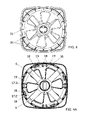
- FIG. 3 shows a top view of the support element from FIG. 1 with spring stage 0 with the lowest spring stiffness being shown;
- FIG. 3 a shows a bottom view of the spring element from FIGS. 1 through 3 in stage 0 of the spring stiffness
- FIG. 3 b shows a schematic partial view of the corrugated spring element that is part of the support element according to the invention in stage 0 of the spring stiffness;
- FIG. 4 shows a top view of the spring element according to the invention in stage 1 with somewhat higher spring stiffness
- FIG. 4 a shows a bottom view of the support element in stage 1 of spring stiffness
- FIG. 4 b shows a schematic partial view according to FIG. 3 b of the corrugated spring element in stage 1 of spring stiffness
- FIG. 5 shows a top view of the support element according to the invention in stage 2 of spring stiffness, an increase over stage 1 ;
- FIG. 5 a shows a bottom view of the support element from FIG. 5 ;
- FIG. 5 b shows a schematic partial view of the corrugated spring element in stage 2 of spring stiffness
- FIG. 6 shows a top view of the support element according to the invention in stage 3 with the highest degree of spring stiffness
- FIG. 6 a shows a bottom view of the support element from FIG. 6 ;
- FIG. 6 b shows a schematic partial view of the corrugated spring area of the support element in stage 3 with the highest degree of spring stiffness of the spring element
- FIG. 7 shows a perspective view of the support element according to the invention without mounted support disc
- FIG. 8 shows a lateral view of the support element without support disc according to FIG. 7 ;
- FIG. 9 shows a top view of the support element without support disc according to FIGS. 7 and 8 ;
- FIG. 10 shows a perspective view from the bottom of a single support disk that is part of the support element
- FIG. 11 shows a top view from the top onto the support disc of FIG. 10 ;
- FIG. 12 shows a lateral view of the support disk of FIGS. 10 and 11 ;
- FIG. 13 shows a stiffness diagram of the support element according to the invention as a function of the forces acting on the support element for the different adjusting stages 0 through 3 .
- the support element marked with reference number 1 in all Figures comprises a base plate 2 in its lower area to which a fastening device 3 , which is not shown in detail, for fixing the support element 1 is arranged on a slatted bed frame or a plate-shaped sub-bed structure.
- the fastening device 3 can have different designs and can be a customary screw connection, for example. To ensure that the support elements can be easily replaced, however, it also is possible to use easily loosening fastening techniques such as quarter-turn fasteners that can be loosened without any tools.
- quarter-turn fasteners it is possible to place a quarter-turn hook with a customary design through the opening 4 in the base plate 2 of the support element 1 . Rotating the support element 1 then causes the long-shaped quarter-turn hook to rest against the upper side of the base plate, causing the support element to be fixed on the corresponding sub-structure in the form of a slatted bed frame or a different sub-bed structure. Releasing it requires the reverse order by rotating the support element and then lifting the base plate from the quarter-turn hook.
- the support element 1 has a plurality of spring arms 6 that slant upward.
- four spring arms are distributed symmetrically across the circumference of the support element:
- the spring arms 6 have corrugated spring elements 7 on their upper end that faces away from the base plate 2 , said corrugated spring elements substantially determining the spring properties of the support element.
- Each corrugated spring element 7 is comprised of two spring legs 11 and 12 located on concentric ring tracks 9 and 10 disposed about the central axis 8 .
- the upper free end of the spring leg 11 is connected to the end of the spring arm 6 , its lower free end is connected to the lower end of the spring leg 12 by means of a connecting bar 13 .
- the upper free end of the spring leg 12 is connected to a frame part 15 that is part of a support plate 14 .
- the frame part 15 has a substantially rectangular outer shape and comprises a center recess into which a support disc 16 is inserted.
- the support disc 16 is rotatable about the central axis 8 of the support element 1 and placed on retaining shoulders 23 that prevent the support disc 16 from falling through into the direction of the base plate 2 .
- the retaining shoulders 23 as can especially be seen in FIGS. 7 , 8 , and 9 , are disposed on both sides of the spring arms 6 with the corrugated spring elements 7 disposed thereon.
- a plurality of bars 17 . 1 , 17 . 2 , and preferably 17 . 3 are arranged concentrically on a mutual ring track with a bar-free area between the adjacent bars 17 . 3 and 17 . 1 .
- the disposition of the bars 17 . 1 , 17 . 2 , and 17 . 3 can be taken from the bottom views of the support element according to FIGS. 3 a , 4 a , 5 a , and 6 a .
- the bars 17 . 1 , 17 . 2 , and 17 . 3 as well as the bar-free position next to the bar 17 . 1 or 17 . 3 , respectively, are associated with a corrugated spring element 7 and form an assembly each so that there are a total of twelve bars in four groups on the ring track.
- the support disc 16 is rotatable within the frame part 15 , it is possible to push one bar 17 . 1 , 17 . 2 , or 17 . 3 of an assembly into the U-shaped intermediate space of the two spring legs 11 and 12 of a corrugated spring element 7 .
- the movement of spring legs 11 and 12 is limited to a different degree after a bar is pushed into the intermediate space of the spring legs 11 and 12 when weight is applied to the support element 1 .
- the restriction or limitation of the movement of the spring legs 11 and 12 results in an increase in stiffness of the support element so that it is possible to set different degrees of spring hardness by rotating the support disc 16 .
- FIG. 3 shows that the alphanumeric identification of stage 0 in the lower bottom corner of the support element in the drawing indicates the softest spring constant.
- the bottom view of the support element 1 in FIG. 3 a shows that in this stage 0 none of the bars is pushed into the intermediate space between the spring legs 11 and 12 of a corrugated spring element 7 .
- the spring legs 11 and 12 thus can carry out an unrestricted movement according to FIG. 3 b and thus an unlimited spring effect.
- FIG. 3 a also shows that the bars 17 . 1 , 17 . 2 , and 17 . 3 have outer stiffening ribs 18 and inner stiffening ribs 19 along their perpendicular lateral faces.
- the number of stiffening ribs in this exemplary embodiment is two each on each of the bars 17 . 2 and 17 . 3 for the outer stiffening ribs 18 as well as for the inner stiffening ribs 19 .
- FIG. 3 a also shows that the bar 17 . 2 has two outer stiffening ribs 18 and bar 17 . 3 has outer stiffening ribs 18 as well as inner stiffening ribs 19 .
- the design of the stiffening ribs varies, as is shown in the presentation of FIGS.
- stiffening ribs 18 and 19 in connection with the cross-section design in the shape of a rectangle of the bars 17 . 1 , 17 . 2 , and 17 . 3 , must provide the bars with different degrees of yield.
- FIGS. 5 and 5 a show that on one hand the top view shows stage 2 as rotating position, which simultaneously causes bar 17 . 2 to be placed in the intermediate space between the spring legs 11 and 12 of the corrugated spring element 7 .
- FIGS. 6 and 6 a finally show the support element 1 according to the invention in stage 3 , in which the bar 17 . 3 , on which outer stiffening ribs 18 as well as inner stiffening ribs 19 are disposed, is placed in the intermediate space between the spring legs 11 and 12 by rotating the support disc 16 .
- stage 3 of the support element provides the highest degree of spring stiffness since now the spring deflection occurs only as a consequence of the elastic properties of the spring arms 6 .
- the support disc 16 In order to fix the individual stages 0 to 3 of the spring stiffness of the support element 1 , there is a snap-in locking device on the support disc 16 and the frame part 15 that is comprised of a plurality of latches 20 that are disposed in the middle between the spring arms 6 on the bottom of the frame part 15 oriented towards the base plate, which can especially be seen in FIG. 9 .
- the latches 20 are functionally connected with latch recesses 21 disposed on the top of the support disc 16 , into which the latches 20 engage and thus fix the respective spring stiffness stages 0 to 3 .
- the support disc 16 furthermore has a display device 22 , as already mentioned, that is comprised of alphanumeric characters.
- FIG. 13 shows a path/force/stiffness diagram. This diagram clearly shows that in stage 0 there is a higher degree of yield in relation to the forces that act on the support element, i.e. there is a longer spring path of the support element. This spring path is restricted by approx. two millimeters in stage 1 , provided the same force of four kilograms is applied for the deflection.
- stage 2 the spring stiffness is even higher so that there is an additional restriction of the spring path.
- stage 3 the diagram in FIG. 13 shows stage 3 in which the corrugated spring elements in principle are blocked due to the special design of the bars 17 . 3 .
- the support element can optimally be equipped with a so-called airlift function.
- the airlift function is integrated into the support disc 16 and substantially is comprised of the support disc 16 having a plurality of, in the present case, six support faces 24 . 1 , 24 . 2 , 24 . 3 , 24 . 4 , 24 . 5 , and 24 . 6 that, in the present case, have a triangular design and whose one lateral region is fixed in the outer edge region of the support disc 16 .
- the embodiment of the support faces 24 . 1 through 24 . 6 is such that when weight is applied to the support element with the cushion cover only lying on the support disc 16 in the form of a mattress, for example, the cushion cover only lies on the front edge regions of the support faces 24 . 1 through 24 . 6 oriented towards the central axis 8 .
- This results in a point-shaped support so that there is better back ventilation of the cushion cover or the mattress, respectively, compared to customary support elements.
- the support faces that slant upwards together with the frame part form an overall uniform support plane 25 so that the cushion cover is supported contiguously.
- the support faces are arranged symmetrically in relation to the central axis on the support disc 16 whereby the number of support faces 24 . 1 through 24 . 6 of course can be different than shown in the exemplary embodiment. Furthermore, the shape of the support faces 24 . 1 through 24 . 6 can be different as well.
- the angle of the support faces 24 . 1 through 24 . 6 in relation to the support plane 25 can range between 5 and 40 degrees according to an advantageous design. The selection of the angle depends on the elastic properties of the plastic material of the support disc 16 as well as on the weight of the cushion elements resting on the individual support elements.
Landscapes
- Mattresses And Other Support Structures For Chairs And Beds (AREA)
Applications Claiming Priority (4)
| Application Number | Priority Date | Filing Date | Title |
|---|---|---|---|
| DE202007000005.7 | 2007-04-02 | ||
| DE202007000005U DE202007000005U1 (de) | 2007-04-02 | 2007-04-02 | Lagerelement für eine Polsterauflage von Sitz- und Liegeflächen |
| DE202007000005U | 2007-04-02 | ||
| PCT/EP2007/064156 WO2008119400A1 (de) | 2007-04-02 | 2007-12-19 | Lagerelement für eine polsterauflage von sitz- und liegeflächen |
Publications (2)
| Publication Number | Publication Date |
|---|---|
| US20100058536A1 US20100058536A1 (en) | 2010-03-11 |
| US8256043B2 true US8256043B2 (en) | 2012-09-04 |
Family
ID=39276184
Family Applications (1)
| Application Number | Title | Priority Date | Filing Date |
|---|---|---|---|
| US12/594,346 Active 2028-09-21 US8256043B2 (en) | 2007-04-02 | 2007-12-19 | Support element for a cushion cover for seating and lying areas |
Country Status (8)
| Country | Link |
|---|---|
| US (1) | US8256043B2 (da) |
| EP (1) | EP2139366B1 (da) |
| CN (1) | CN101652086B (da) |
| DE (1) | DE202007000005U1 (da) |
| DK (1) | DK2139366T3 (da) |
| ES (1) | ES2386208T3 (da) |
| PL (1) | PL2139366T3 (da) |
| WO (1) | WO2008119400A1 (da) |
Cited By (15)
| Publication number | Priority date | Publication date | Assignee | Title |
|---|---|---|---|---|
| US20190150621A1 (en) * | 2016-09-29 | 2019-05-23 | Steelcase Inc. | Compliant seating structure |
| EP3892156A1 (en) | 2020-04-07 | 2021-10-13 | LG Electronics Inc. | Bed |
| EP3892155A1 (en) | 2020-04-07 | 2021-10-13 | LG Electronics Inc. | Bed |
| EP3892159A1 (en) | 2020-04-07 | 2021-10-13 | LG Electronics Inc. | Bed |
| EP3892160A1 (en) | 2020-04-07 | 2021-10-13 | LG Electronics Inc. | Bed |
| EP3892158A1 (en) | 2020-04-07 | 2021-10-13 | LG Electronics Inc. | Bed |
| EP3892161A1 (en) | 2020-04-07 | 2021-10-13 | LG Electronics Inc. | Bed |
| EP3892157A1 (en) | 2020-04-07 | 2021-10-13 | LG Electronics Inc. | Bed |
| KR20210124676A (ko) | 2020-04-07 | 2021-10-15 | 엘지전자 주식회사 | 쿠션 강도 제어 유닛 및 이를 구비한 침대 |
| KR20210124674A (ko) | 2020-04-07 | 2021-10-15 | 엘지전자 주식회사 | 쿠션 부재 및 이를 구비하는 침대 |
| KR20210124678A (ko) | 2020-04-07 | 2021-10-15 | 엘지전자 주식회사 | 쿠션 부재 및 이를 구비하는 침대 |
| EP3895582A1 (en) | 2020-04-07 | 2021-10-20 | LG Electronics Inc. | Bed |
| EP3903645A1 (en) | 2020-04-07 | 2021-11-03 | LG Electronics Inc. | Bed |
| US11324323B2 (en) | 2019-09-18 | 2022-05-10 | Steelcase Inc. | Body support member with lattice structure |
| US11464344B2 (en) | 2020-04-07 | 2022-10-11 | Lg Electronics Inc. | Bed |
Families Citing this family (9)
| Publication number | Priority date | Publication date | Assignee | Title |
|---|---|---|---|---|
| DE202009004803U1 (de) * | 2009-05-12 | 2010-07-15 | Froli Kunststoffwerk Heinrich Fromme Ohg | Federkernelement für den Einsatz in eine Matratze, beispielsweise Taschenfederkernmatratze |
| DE102010045733A1 (de) * | 2010-07-30 | 2012-02-02 | Siegbert Hartmann | Auflagerelement einer Sitz- oder Liegemöbelunterfederung |
| DE202010015380U1 (de) * | 2010-11-11 | 2012-02-17 | Hermann Bock Gmbh | Federelement |
| DE202011050741U1 (de) | 2011-07-15 | 2012-07-16 | Froli Kunststoffwerk Heinrich Fromme Ohg | Auflagevorrichtung für eine Polsterunterlage einer Liege- oder Sitzfläche |
| DE202014104824U1 (de) * | 2014-10-08 | 2015-10-09 | Froli Kunststoffwerk Heinrich Fromme, Inh. Margret Fromme-Ruthmann E.Kfr. | Anordnung mit mehreren Federelementen für eine Polsterunterlage |
| FR3035579B1 (fr) * | 2015-04-30 | 2017-12-08 | Tournadre Sa Standard Gum | Dispositif monobloc de suspension de matelas |
| EP3403538A1 (en) * | 2017-05-16 | 2018-11-21 | Bekina Indurub | Adaptable mattress support element |
| CN110397701A (zh) * | 2019-06-17 | 2019-11-01 | 华为技术有限公司 | 一种隔振装置、隔振系统及交通工具 |
| DE202023104680U1 (de) * | 2023-08-17 | 2023-09-07 | Froli Kunststoffwerk e.Kfr. | Federelement für eine Polsterunterlage und Anordnung mit mehreren Federelementen |
Citations (3)
| Publication number | Priority date | Publication date | Assignee | Title |
|---|---|---|---|---|
| DE20108407U1 (de) | 2000-05-18 | 2001-08-02 | Diemer, Gregor, 85456 Wartenberg | Stützelement |
| EP1386564A1 (de) | 2002-07-31 | 2004-02-04 | Froli Kunststoffwerk Heinrich Fromme OHG | Federelement für Sitz- und Liegemöbel |
| DE20318252U1 (de) | 2003-11-24 | 2004-12-30 | Froli Kunststoffwerk Heinrich Fromme Ohg | Polsterung für Sitze und Rückenlehnen |
Family Cites Families (3)
| Publication number | Priority date | Publication date | Assignee | Title |
|---|---|---|---|---|
| DE29712720U1 (de) * | 1997-07-18 | 1998-09-10 | Froli Kunststoffe Heinrich Fromme, 33758 Schloß Holte-Stukenbrock | Lagerelement für Sitz- oder Liegeflächen sowie Unterbau dafür |
| DE29916753U1 (de) * | 1999-09-23 | 2000-11-23 | FROLI Kunststoffwerk Heinrich Fromme oHG, 33758 Schloß Holte-Stukenbrock | Federelement für Sitz- oder Liegeflächen |
| DE202005010441U1 (de) * | 2005-06-30 | 2006-08-10 | Froli Kunststoffwerk Heinrich Fromme Ohg | Federelement für Polsterungen mit Oberfeder und Unterfeder |
-
2007
- 2007-04-02 DE DE202007000005U patent/DE202007000005U1/de not_active Expired - Lifetime
- 2007-12-19 US US12/594,346 patent/US8256043B2/en active Active
- 2007-12-19 DK DK07857780.6T patent/DK2139366T3/da active
- 2007-12-19 PL PL07857780T patent/PL2139366T3/pl unknown
- 2007-12-19 ES ES07857780T patent/ES2386208T3/es active Active
- 2007-12-19 CN CN200780052446.7A patent/CN101652086B/zh active Active
- 2007-12-19 WO PCT/EP2007/064156 patent/WO2008119400A1/de not_active Ceased
- 2007-12-19 EP EP07857780A patent/EP2139366B1/de active Active
Patent Citations (4)
| Publication number | Priority date | Publication date | Assignee | Title |
|---|---|---|---|---|
| DE20108407U1 (de) | 2000-05-18 | 2001-08-02 | Diemer, Gregor, 85456 Wartenberg | Stützelement |
| EP1386564A1 (de) | 2002-07-31 | 2004-02-04 | Froli Kunststoffwerk Heinrich Fromme OHG | Federelement für Sitz- und Liegemöbel |
| US6826791B2 (en) * | 2002-07-31 | 2004-12-07 | Froli Kunststoffwerk Heinrich Fromme Ohg | Spring element for beds or chairs |
| DE20318252U1 (de) | 2003-11-24 | 2004-12-30 | Froli Kunststoffwerk Heinrich Fromme Ohg | Polsterung für Sitze und Rückenlehnen |
Non-Patent Citations (1)
| Title |
|---|
| International Search Report for corresponding International Application PCT/EP2007/064156. |
Cited By (26)
| Publication number | Priority date | Publication date | Assignee | Title |
|---|---|---|---|---|
| US20190150621A1 (en) * | 2016-09-29 | 2019-05-23 | Steelcase Inc. | Compliant seating structure |
| US10820705B2 (en) * | 2016-09-29 | 2020-11-03 | Steelcase Inc. | Compliant seating structure |
| US12150556B2 (en) | 2016-09-29 | 2024-11-26 | Steelcase Inc. | Compliant seating structure |
| US11771227B2 (en) | 2016-09-29 | 2023-10-03 | Steelcase Inc. | Compliant seating structure |
| US11324322B2 (en) * | 2016-09-29 | 2022-05-10 | Steelcase Inc. | Compliant seating structure |
| US12329290B2 (en) | 2019-09-18 | 2025-06-17 | Steelcase Inc. | Body support member with lattice structure |
| US11974676B2 (en) | 2019-09-18 | 2024-05-07 | Steelcase Inc. | Body support member with lattice structure |
| US11324323B2 (en) | 2019-09-18 | 2022-05-10 | Steelcase Inc. | Body support member with lattice structure |
| EP3895582A1 (en) | 2020-04-07 | 2021-10-20 | LG Electronics Inc. | Bed |
| EP3892160A1 (en) | 2020-04-07 | 2021-10-13 | LG Electronics Inc. | Bed |
| KR20210124674A (ko) | 2020-04-07 | 2021-10-15 | 엘지전자 주식회사 | 쿠션 부재 및 이를 구비하는 침대 |
| KR20210124678A (ko) | 2020-04-07 | 2021-10-15 | 엘지전자 주식회사 | 쿠션 부재 및 이를 구비하는 침대 |
| EP3892157A1 (en) | 2020-04-07 | 2021-10-13 | LG Electronics Inc. | Bed |
| EP3903645A1 (en) | 2020-04-07 | 2021-11-03 | LG Electronics Inc. | Bed |
| EP3892161A1 (en) | 2020-04-07 | 2021-10-13 | LG Electronics Inc. | Bed |
| EP3892158A1 (en) | 2020-04-07 | 2021-10-13 | LG Electronics Inc. | Bed |
| US11464344B2 (en) | 2020-04-07 | 2022-10-11 | Lg Electronics Inc. | Bed |
| KR20210124676A (ko) | 2020-04-07 | 2021-10-15 | 엘지전자 주식회사 | 쿠션 강도 제어 유닛 및 이를 구비한 침대 |
| US11779126B2 (en) | 2020-04-07 | 2023-10-10 | Lg Electronics Inc. | Bed |
| US11779125B2 (en) | 2020-04-07 | 2023-10-10 | Lg Electronics Inc. | Bed |
| US11786046B2 (en) | 2020-04-07 | 2023-10-17 | Lg Electronics Inc. | Bed |
| US11896131B2 (en) | 2020-04-07 | 2024-02-13 | Lg Electronics Inc. | Bed |
| EP3892159A1 (en) | 2020-04-07 | 2021-10-13 | LG Electronics Inc. | Bed |
| EP3892155A1 (en) | 2020-04-07 | 2021-10-13 | LG Electronics Inc. | Bed |
| US12226018B2 (en) | 2020-04-07 | 2025-02-18 | Lg Electronics Inc. | Bed |
| EP3892156A1 (en) | 2020-04-07 | 2021-10-13 | LG Electronics Inc. | Bed |
Also Published As
| Publication number | Publication date |
|---|---|
| CN101652086A (zh) | 2010-02-17 |
| CN101652086B (zh) | 2012-11-07 |
| DK2139366T3 (da) | 2012-08-27 |
| DE202007000005U1 (de) | 2008-05-08 |
| EP2139366B1 (de) | 2012-05-16 |
| EP2139366A1 (de) | 2010-01-06 |
| ES2386208T3 (es) | 2012-08-13 |
| WO2008119400A1 (de) | 2008-10-09 |
| US20100058536A1 (en) | 2010-03-11 |
| PL2139366T3 (pl) | 2012-10-31 |
Similar Documents
| Publication | Publication Date | Title |
|---|---|---|
| US8256043B2 (en) | Support element for a cushion cover for seating and lying areas | |
| US7740321B2 (en) | Suspended pixelated seating structure | |
| US7832040B2 (en) | Suspended flexible matrix support system | |
| JPH08252151A (ja) | 規則的パターンで配置された多数のばね要素を有するクッションエレメント | |
| CZ292929B6 (cs) | Pružicí prvek pro polštářování sedacích nebo lůžkových ploch a lůžkový systém s takovými pružicími prvky | |
| JPH0344762B2 (da) | ||
| US8020224B2 (en) | Internal corner structure for mattress foundations | |
| JP3792729B2 (ja) | マットレス台の為のばね橋 | |
| JP2000125994A (ja) | 樹脂性クッションエレメント | |
| CA2881101C (en) | Mattress including flat springs | |
| US20020069463A1 (en) | Stackable bedding foundation | |
| US7297389B2 (en) | Top plate for a unitary suspension device of a multi-element bed base | |
| US6859959B2 (en) | Spring lath for sitting or reclining furniture | |
| CN212139985U (zh) | 床上用品系统、床垫支承件以及床垫构造 | |
| US7296310B2 (en) | Adjustable mattress foundation | |
| CN101296639B (zh) | 床 | |
| KR20170004062A (ko) | 매트리스 쿠션용 파운데이션 | |
| US11839309B2 (en) | Mattress | |
| KR101796123B1 (ko) | 보강용 탄성블럭이 구비된 셀프포켓 매트리스 | |
| US11819134B2 (en) | Mattress | |
| US10334956B2 (en) | One-piece mattress suspension device | |
| KR102165892B1 (ko) | 사계절 사용이 가능한 모듈형 침대 | |
| JP3010128B2 (ja) | 弾性支持装置 | |
| JPH1156534A (ja) | マットレス用スプリング | |
| US20100038946A1 (en) | Seat damper assembly |
Legal Events
| Date | Code | Title | Description |
|---|---|---|---|
| AS | Assignment |
Owner name: FROLI KUNSTSTOFFWERK HEINRICH FROMME OHG,GERMANY Free format text: ASSIGNMENT OF ASSIGNORS INTEREST;ASSIGNOR:FROMME-RUTHMANN, MARGRET;REEL/FRAME:023316/0669 Effective date: 20090910 Owner name: FROLI KUNSTSTOFFWERK HEINRICH FROMME OHG, GERMANY Free format text: ASSIGNMENT OF ASSIGNORS INTEREST;ASSIGNOR:FROMME-RUTHMANN, MARGRET;REEL/FRAME:023316/0669 Effective date: 20090910 |
|
| STCF | Information on status: patent grant |
Free format text: PATENTED CASE |
|
| FPAY | Fee payment |
Year of fee payment: 4 |
|
| MAFP | Maintenance fee payment |
Free format text: PAYMENT OF MAINTENANCE FEE, 8TH YR, SMALL ENTITY (ORIGINAL EVENT CODE: M2552); ENTITY STATUS OF PATENT OWNER: SMALL ENTITY Year of fee payment: 8 |
|
| MAFP | Maintenance fee payment |
Free format text: PAYMENT OF MAINTENANCE FEE, 12TH YR, SMALL ENTITY (ORIGINAL EVENT CODE: M2553); ENTITY STATUS OF PATENT OWNER: SMALL ENTITY Year of fee payment: 12 |