US8150585B2 - Control system for automatic transmission - Google Patents
Control system for automatic transmission Download PDFInfo
- Publication number
- US8150585B2 US8150585B2 US12/400,329 US40032909A US8150585B2 US 8150585 B2 US8150585 B2 US 8150585B2 US 40032909 A US40032909 A US 40032909A US 8150585 B2 US8150585 B2 US 8150585B2
- Authority
- US
- United States
- Prior art keywords
- learning
- time
- amount
- command value
- engagement pressure
- Prior art date
- Legal status (The legal status is an assumption and is not a legal conclusion. Google has not performed a legal analysis and makes no representation as to the accuracy of the status listed.)
- Active, expires
Links
Images


Classifications
-
- F—MECHANICAL ENGINEERING; LIGHTING; HEATING; WEAPONS; BLASTING
- F16—ENGINEERING ELEMENTS AND UNITS; GENERAL MEASURES FOR PRODUCING AND MAINTAINING EFFECTIVE FUNCTIONING OF MACHINES OR INSTALLATIONS; THERMAL INSULATION IN GENERAL
- F16H—GEARING
- F16H61/00—Control functions within control units of change-speed- or reversing-gearings for conveying rotary motion ; Control of exclusively fluid gearing, friction gearing, gearings with endless flexible members or other particular types of gearing
- F16H61/04—Smoothing ratio shift
- F16H61/06—Smoothing ratio shift by controlling rate of change of fluid pressure
- F16H61/061—Smoothing ratio shift by controlling rate of change of fluid pressure using electric control means
-
- F—MECHANICAL ENGINEERING; LIGHTING; HEATING; WEAPONS; BLASTING
- F16—ENGINEERING ELEMENTS AND UNITS; GENERAL MEASURES FOR PRODUCING AND MAINTAINING EFFECTIVE FUNCTIONING OF MACHINES OR INSTALLATIONS; THERMAL INSULATION IN GENERAL
- F16H—GEARING
- F16H61/00—Control functions within control units of change-speed- or reversing-gearings for conveying rotary motion ; Control of exclusively fluid gearing, friction gearing, gearings with endless flexible members or other particular types of gearing
- F16H61/04—Smoothing ratio shift
- F16H61/06—Smoothing ratio shift by controlling rate of change of fluid pressure
-
- F—MECHANICAL ENGINEERING; LIGHTING; HEATING; WEAPONS; BLASTING
- F16—ENGINEERING ELEMENTS AND UNITS; GENERAL MEASURES FOR PRODUCING AND MAINTAINING EFFECTIVE FUNCTIONING OF MACHINES OR INSTALLATIONS; THERMAL INSULATION IN GENERAL
- F16H—GEARING
- F16H59/00—Control inputs to control units of change-speed-, or reversing-gearings for conveying rotary motion
- F16H59/14—Inputs being a function of torque or torque demand
-
- F—MECHANICAL ENGINEERING; LIGHTING; HEATING; WEAPONS; BLASTING
- F16—ENGINEERING ELEMENTS AND UNITS; GENERAL MEASURES FOR PRODUCING AND MAINTAINING EFFECTIVE FUNCTIONING OF MACHINES OR INSTALLATIONS; THERMAL INSULATION IN GENERAL
- F16H—GEARING
- F16H59/00—Control inputs to control units of change-speed-, or reversing-gearings for conveying rotary motion
- F16H59/68—Inputs being a function of gearing status
- F16H59/72—Inputs being a function of gearing status dependent on oil characteristics, e.g. temperature, viscosity
-
- F—MECHANICAL ENGINEERING; LIGHTING; HEATING; WEAPONS; BLASTING
- F16—ENGINEERING ELEMENTS AND UNITS; GENERAL MEASURES FOR PRODUCING AND MAINTAINING EFFECTIVE FUNCTIONING OF MACHINES OR INSTALLATIONS; THERMAL INSULATION IN GENERAL
- F16H—GEARING
- F16H61/00—Control functions within control units of change-speed- or reversing-gearings for conveying rotary motion ; Control of exclusively fluid gearing, friction gearing, gearings with endless flexible members or other particular types of gearing
- F16H61/12—Detecting malfunction or potential malfunction, e.g. fail safe; Circumventing or fixing failures
-
- F—MECHANICAL ENGINEERING; LIGHTING; HEATING; WEAPONS; BLASTING
- F16—ENGINEERING ELEMENTS AND UNITS; GENERAL MEASURES FOR PRODUCING AND MAINTAINING EFFECTIVE FUNCTIONING OF MACHINES OR INSTALLATIONS; THERMAL INSULATION IN GENERAL
- F16H—GEARING
- F16H61/00—Control functions within control units of change-speed- or reversing-gearings for conveying rotary motion ; Control of exclusively fluid gearing, friction gearing, gearings with endless flexible members or other particular types of gearing
- F16H2061/0075—Control functions within control units of change-speed- or reversing-gearings for conveying rotary motion ; Control of exclusively fluid gearing, friction gearing, gearings with endless flexible members or other particular types of gearing characterised by a particular control method
- F16H2061/0087—Adaptive control, e.g. the control parameters adapted by learning
-
- F—MECHANICAL ENGINEERING; LIGHTING; HEATING; WEAPONS; BLASTING
- F16—ENGINEERING ELEMENTS AND UNITS; GENERAL MEASURES FOR PRODUCING AND MAINTAINING EFFECTIVE FUNCTIONING OF MACHINES OR INSTALLATIONS; THERMAL INSULATION IN GENERAL
- F16H—GEARING
- F16H61/00—Control functions within control units of change-speed- or reversing-gearings for conveying rotary motion ; Control of exclusively fluid gearing, friction gearing, gearings with endless flexible members or other particular types of gearing
- F16H61/02—Control functions within control units of change-speed- or reversing-gearings for conveying rotary motion ; Control of exclusively fluid gearing, friction gearing, gearings with endless flexible members or other particular types of gearing characterised by the signals used
- F16H61/0202—Control functions within control units of change-speed- or reversing-gearings for conveying rotary motion ; Control of exclusively fluid gearing, friction gearing, gearings with endless flexible members or other particular types of gearing characterised by the signals used the signals being electric
- F16H61/0251—Elements specially adapted for electric control units, e.g. valves for converting electrical signals to fluid signals
- F16H2061/0258—Proportional solenoid valve
Definitions
- the present invention relates to a control system for an automatic transmission which includes a solenoid valve for producing solenoid pressure in response to application of a solenoid current thereto, and performs learning control of engagement pressure to be applied to frictional engagement elements which are engaged and released upon shifting.
- Japanese Patent Application First Publication No. 2005-282810 discloses a control system for an automatic transmission which performs learning control of an engagement pressure command value (such as clutch pressure command value and brake pressure command value) that is output until a torque phase is terminated upon the next shifting on the basis of a rate of change of the gear ratio in an inertia phase in order to suppress variation in acceleration of a vehicle from a torque phase to an initial stage of the previous inertia phase.
- an engagement pressure command value such as clutch pressure command value and brake pressure command value
- Japanese Patent Application First Publication No. 2002-276799 discloses a control system for an automatic transmission in which throttle opening TVO (engine load) is divided into a plurality of throttle opening regions and learning correction amounts corresponding to the respective throttle opening regions are set and stored in order to prevent excess or lack of the respective learning correction amounts depending on variation in throttle opening TVO.
- throttle opening TVO engine load
- learning correction amounts corresponding to the respective throttle opening regions are set and stored in order to prevent excess or lack of the respective learning correction amounts depending on variation in throttle opening TVO.
- an engagement pressure command value is corrected by using the learning correction amount corresponding to the throttle opening region which is set and stored at the current shifting stage.
- a drop of the hydraulic pressure in the automatic transmission is caused due to adhesion of a magnetic contaminant to a magnetic attraction portion of the solenoid valve which is an example of the posterior deterioration of a control mechanism in the control system for an automatic transmission.
- An amount of the drop of the hydraulic pressure due to the adhesion of a magnetic contaminant is increased as the engagement pressure command value becomes large. Therefore, a correction amount of the engagement pressure command value learned in a region beyond the certain degree (1 ⁇ 8) of throttle opening TVO where the engagement pressure command value becomes large, tends to be excessively small. In contrast, a correction amount of the engagement pressure command value learned in a region below the certain degree (1 ⁇ 8) of throttle opening TVO where the engagement pressure command value becomes small, becomes excessively large.
- An object of the present invention is to provide a control system for an automatic transmission which is capable of eliminating influence of the time-dependent deterioration that occurs in the control mechanism, by establishing a control software system that realizes a learning correction without necessitating an increased storage capacity and without causing an extreme increase or an extreme decrease in learning correction amount, and capable of attaining a desired shifting operation continuously for a long time.
- control system for an automatic transmission comprising:
- a control method for controlling an automatic transmission including a friction engagement element that is engaged or released upon shifting, a solenoid valve that produces a solenoid pressure by application of a solenoid current, an engagement pressure control valve that receives the solenoid pressure as an operating signal pressure and controls an engagement pressure to be supplied to the friction engagement element according to the solenoid pressure, and an electronic control unit for controlling the solenoid current which includes a learning correction amount setting and storing section for setting and storing a learning correction amount that is obtained when shifting is experienced and an engagement pressure command value learning correction section for correcting an engagement pressure command value that is calculated according to a shifting transition state by using the learning correction amount, wherein the learning correction amount is divided into an initial learning amount that has no dependence upon the engagement pressure command value and converges into a constant amount owing to individual variation, and a time-dependent deterioration amount that has dependence upon the engagement pressure command value and varies owing to posterior deterioration of a control mechanism, the control
- FIG. 1 is a schematic block diagram showing a whole control system for an automatic transmission installed in a vehicle with an engine, of an embodiment of the present invention.
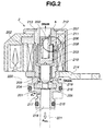
- FIG. 2 is a cross-section of a normal-high linear solenoid valve as an example of a solenoid valve which is applied to the control system of the embodiment of the present invention.
- FIG. 3 is a flowchart showing a routine of a learning correction amount setting and storing process which is executed by an automatic transmission control unit in the control system of the embodiment.
- FIG. 4 is a flowchart showing a routine of an engagement pressure command value learning correction process which is executed by an automatic transmission control unit in the control system of the embodiment.
- FIG. 5A is an enlarged view of a magnetic attraction portion of a normal-high linear solenoid valve that is applicable to the control system of the embodiment, and shows no contaminant adhered to the magnetic attraction portion and a magnetic gap at the magnetic attraction portion.
- FIG. 5B is an enlarged view of a magnetic attraction portion of a normal-high linear solenoid valve that is applicable to the control system of the embodiment, and shows a contaminant adhered to the magnetic attraction portion and a magnetic gap at the magnetic attraction portion.
- FIG. 6 is a diagram showing a relationship between a number of endurance cycles of a normal-high linear solenoid valve applicable to the control system of the embodiment and an amount of the contaminant adhered to the magnetic attraction portion of the normal-high linear solenoid valve, and a relationship between the amount of the contaminant adhered to the magnetic attraction portion and an amount of drop in clutch pressure.
- FIG. 7 is a time chart showing output torque, rate of change in gear ratio, gear ratio and upshift engagement pressure command during an upshift transition (as an example of a shift transition) for the sake of explanation of hydraulic pressure correction by piston stroke learning which is performed in the control system of the embodiment.
- FIG. 8 is a diagram showing a relationship between oil temperatures in the automatic transmission, correction values in learning regions, and updating and reflection in the control system of the embodiment.
- FIG. 9 is a block diagram showing an operation process to derive a final engagement pressure command value in the learning correction for eliminating influence of time-dependent deterioration in the control system of the embodiment.
- FIG. 10 is a diagram showing a relationship between frequency of PS learning and PS learning region correction amount that is obtained as a sum of a PS initial learning amount and a learning region time-dependent deterioration amount.
- FIG. 11 is a diagram showing an input and output characteristic curve of a new normal-high linear solenoid valve in the control system of the embodiment which has no contaminant adhesion, and an input and output characteristic curve of a used normal-high linear solenoid valve in the control system of the embodiment which has contaminant adhesion.
- FIG. 12 is a diagram showing a time-dependent deterioration data that is preliminarily set and stored in an engagement pressure command value learning correction section of the control system of the embodiment.
- FIG. 1 is a schematic block diagram showing the control system of the embodiment which is applied to a shift control system.
- the control system of the embodiment includes friction engagement element 1 , solenoid valve (specifically, normal-high linear solenoid valve) 2 , control valve (specifically, engagement pressure control valve) 3 and automatic transmission electronic control unit (ATCU) 4 .
- solenoid valve specifically, normal-high linear solenoid valve
- control valve specifically, engagement pressure control valve
- ACU automatic transmission electronic control unit
- Friction engagement element 1 is controlled to be engaged or released by engagement pressure Pc that is supplied from control valve 3 upon a transition of shifting.
- Friction engagement element 1 may be a hydraulic multiple disk clutch, a hydraulic multiple disk brake and the like.
- Normal-high linear solenoid valve 2 receives pilot pressure Pp (a constant pressure) as source pressure which is produced by a pilot valve, not shown, and produces solenoid pressure P SOL that is applied to control valve 3 , according to solenoid current I SOL (for instance, duty drive current of 800 Hz) that is controlled by ATCU 4 and applied to normal-high linear solenoid valve 2 .
- pilot pressure Pp a constant pressure
- P SOL solenoid pressure
- Control valve 3 is a regulator spool valve that receives solenoid pressure P SOL as an operating signal pressure from normal-high linear solenoid valve 2 and line pressure P L as source pressure from a line pressure control valve, not shown, and controls engagement pressure Pc that is applied to friction engagement element 1 .
- Control valve 3 performs such hydraulic control that as solenoid pressure P SOL becomes higher, engagement pressure Pc is increased.
- ATCU 4 receives various signals from AT oil temperature sensor 5 as an oil temperature detection element, engine speed sensor 6 , throttle sensor 7 , turbine speed sensor 8 , vehicle speed sensor 9 and other sensors and switches 10 .
- ATCU 4 performs such shift control that a shift start command is output when an operating point based on a throttle opening and a vehicle speed crosses an upshift line or a downshift line in a predetermined shift schedule (for instance, a seven forward speed shift schedule). Further, ATCU 4 performs calculation of an engagement pressure command value in shift transition in accordance with the shift start command and variation in gear ratio Gr that is determined by the turbine speed (i.e., AT input speed) and the vehicle speed (i.e., AT output speed).
- ATCU 4 performs learning correction amount setting and storing process (see FIG. 3 ) for setting and storing a learning correction amount that is obtained when the shifting is experienced, and engagement pressure command value learning correction process (see FIG. 4 ) for correcting an engagement pressure command value that is calculated according to a state of the shift transition, with the learning correction amount.
- FIG. 2 is a cross-section of normal-high linear solenoid valve 2 as one example of a solenoid valve that is applied to the control system of the embodiment.
- normal-high linear solenoid valve 2 includes valve housing 201 , solenoid 202 , plunger 203 , valve body 204 , valve seat 205 , spring 206 , shim 207 , plunger bushing 208 , valve body bushing 209 , first bushing support frame 210 , second bushing support frame 211 , shim support frame 212 , valve cover 213 , mounting flange 214 , first seal ring 215 , second seal ring 216 , pilot pressure port 217 , solenoid pressure port 218 , first drain port 219 , and second drain port 220 .
- Plunger bushing 208 and valve body bushing 209 may be made of a suitable plastic material such as PTFE.
- Normal-high linear solenoid valve 2 is fixed to valve body 222 of a valve control unit that is formed with solenoid pressure oil passage 221 , through mounting flange 214 .
- solenoid current I SOL that is applied to solenoid 202 is zero, normal-high linear solenoid valve 2 is placed in a closed position in which valve body 204 and valve seat 5 as a united body are in butt contact with each other by a biasing force of spring 206 which is exerted on plunger 203 and valve body 204 in a downward direction when viewed in FIG. 2 .
- solenoid current I SOL that is applied to solenoid 202 becomes large to generate a magnetic attraction force
- plunger 203 and valve body 204 are urged by the magnetic attraction force so as to move upwardly when viewed in FIG. 2 , against the biasing force of spring 206 to thereby separate valve body 204 from valve seat 205 .
- normal-high linear solenoid valve 2 is brought into an open position. An opening degree of normal-high linear solenoid valve 2 is increased as the magnetic attraction force becomes larger.
- FIG. 3 is a flowchart showing a routine of a learning correction amount setting and storing process which is executed by ATCU 4 in the control system of the embodiment. Referring to FIG. 3 , the routine of the learning correction amount setting and storing process is explained.
- step S 301 throttle opening TVO detected by throttle sensor 7 is read in.
- the routine goes to step S 302 .
- step S 302 subsequent to the read-in of throttle opening TVO in step S 301 , it is judged whether or not throttle opening TVO is not more than a predetermined opening TVO o (for instance, 1 ⁇ 8) that indicates a low input torque region.
- a predetermined opening TVO o for instance, 1 ⁇ 8 that indicates a low input torque region.
- step S 303 subsequent to the judgment of TVO ⁇ TVO o in step S 302 , it is judged whether or not the shift start command is output in a shift control processing section of ATCU 4 .
- the routine goes to step S 304 .
- the routine returns to step S 301 .
- step S 304 subsequent to the judgment of the presence of the output of the shift start command in step S 303 , current timer value T n is obtained by adding “1” to previous timer value T n ⁇ 1 . The routine then goes to step S 305 . Meanwhile, an initial value of the timer value is zero.
- the routine goes to step S 306 .
- the routine returns to step S 304 .
- the judgment as to whether or not the inertia phase is started is conducted by monitoring gear ratio Gr and judging whether or not the change from the gear ratio Gr in the gear stage before shifting to the gear ratio Gr in the gear stage after shifting is started.
- step S 306 subsequent to the judgment that the inertia phase is started in step S 305 , timer value T n that is measured until that time is rewritten to piston stroke time T r of a piston of friction engagement element 1 .
- the routine then goes to step S 307 .
- step S 307 subsequent to the rewrite to piston stroke time T r in step S 306 , AT oil temperature ATF detected by AT oil temperature sensor 5 is read in. The routine then goes to step S 308 .
- step S 308 subsequent to the read-in of AT oil temperature ATF in step S 307 , piston stroke learning region correction amount ⁇ PL (hereinafter referred to as PS learning region correction amount ⁇ PL) is calculated by using the following formula.
- ⁇ PL ⁇ PL m +k ( T r ⁇ T t )
- ⁇ PL m is a PS learning region correction amount already stored in a memory that stores PS learning region correction amount ⁇ PL in which the friction engagement element, shift mode and oil temperature range are identical to those in the current learning
- k is a constant for determining a correction amount with respect to time difference
- T t is a target time of piston stroke time.
- the target time is determined as being a piston stroke time that can achieve high quality shifting causing no shock or prolongation, in accordance with AT oil temperature ATF. Further, an upper limit value and a lower limit value of PS learning region correction amount ⁇ PL are set for each of the friction engagement elements.
- step S 309 subsequent to the calculation of PS learning region correction amount ⁇ PL in step S 308 , it is judged whether or not AT oil temperature ATF is in an ordinary temperature range that is beyond second switching oil temperature T 2 (for instance, 60° C.) and not more than high temperature side inhibit oil temperature T H (for instance, 120° C.)
- the routine goes to step S 310 .
- the routine goes to step S 314 .
- step S 310 subsequent to the judgment that AT oil temperature ATF is in the ordinary temperature range in step S 309 , current number of times n of learning (hereinafter referred to as learning frequency n) is calculated by adding 1 to previous learning frequency n′. The routine then goes to step S 311 .
- learning frequency n current number of times n of learning
- step S 311 subsequent to the calculation of learning frequency n in step S 310 , it is judged whether or not learning frequency n is 10.
- the routine goes to step S 313 .
- the routine goes to step S 312 .
- the reason of the judgment as to whether or not learning frequency n is 10 is that if PS learning region correction is repeatedly experienced in the ordinary temperature range with the identical friction engagement element and shift mode, learning region correction amount ⁇ PL is converged to a stable value in which a difference between a previous value and a current value of PS learning region correction amount ⁇ PL becomes small.
- step S 312 subsequent to the judgment that learning frequency n is less than 10 in step S 311 , PS learning region correction amount ⁇ PL calculated in step S 308 is updated and stored in first memory RAM 1 . The routine then returns to step S 301 .
- PS learning region correction amount ⁇ PL calculated in step S 308 is set as piston stroke initial learning amount ⁇ PI (hereinafter referred to as PS initial learning amount ⁇ PI), and PS initial learning amount ⁇ PI is stored in initial learning amount memory RAMI.
- PS initial learning amount ⁇ PI piston stroke initial learning amount ⁇ PI
- step S 314 subsequent to the judgment that AT oil temperature ATF is out of the ordinary temperature range in step S 309 , it is judged whether or not AT oil temperature ATF is in an intermediate temperature range that is beyond first switching oil temperature T 1 (for instance, 20° C.) and not more than second switching oil temperature T 2 (for instance, 60° C.)
- first switching oil temperature T 1 for instance, 20° C.
- second switching oil temperature T 2 for instance, 60° C.
- step S 315 subsequent to the judgment that AT oil temperature ATF is in the intermediate temperature range (i.e., T 1 ⁇ ATF ⁇ T 2 ) in step S 314 , PS learning region correction amount ⁇ PL calculated in step S 308 is updated and stored in second memory RAM 2 . The routine then returns to step S 301 .
- step S 316 subsequent to the judgment that AT oil temperature ATF is out of the intermediate temperature range in step S 314 , it is judged whether or not AT oil temperature ATF is in a low temperature range that is beyond low temperature side inhibit oil temperature T L (for instance, 0° C.) and not more than first switching oil temperature T 1 (for instance, 20° C.).
- T L low temperature side inhibit oil temperature
- T 1 first switching oil temperature
- step S 317 subsequent to the judgment that AT oil temperature ATF is in the low temperature range (i.e., T L ⁇ ATF ⁇ T 1 ) in step S 316 , PS learning region correction amount ⁇ PL calculated in step S 308 is updated and stored in third memory RAM 3 . The routine then returns to step S 301 .
- FIG. 4 is a flowchart showing a routine of learning correction of an engagement pressure command value which is executed by ATCU 4 in the control system of the embodiment. Referring to FIG. 4 , the routine of the learning correction of the engagement pressure command value is explained.
- the routine of the learning correction of the engagement pressure command value is executed over an entire hydraulic pressure region of the engagement pressure and an entire phase of the release pressure upon upshift control, downshift control and engagement control (N-D, N-R).
- step S 401 it is judged whether or not PS initial learning amount ⁇ PI is stored.
- the routine goes to step S 404 .
- the routine goes to step S 402 .
- step S 402 subsequent to the judgment that PS initial learning amount ⁇ PI is not stored in step S 401 , engagement pressure command value PO (equivalent to clutch pressure command value) and AT oil temperature ATF are read in and PS learning region correction amount ⁇ PL according to AT oil temperature ATF is read in from one of three memories RAM 1 , RAM 2 and RAM 3 .
- the routine then goes to step S 403 .
- step S 403 subsequent to the read-in of engagement pressure command value PO, AT oil temperature ATF and PS learning region correction amount ⁇ PL according to AT oil temperature ATF in step S 402 , final engagement pressure command value PO* is calculated by adding PS learning region correction amount ⁇ PL to engagement pressure command value PO.
- the routine then goes to step S 412 .
- step S 404 subsequent to the judgment that PS initial learning amount ⁇ PI is stored in step S 401 , engagement pressure command value PO and AT oil temperature ATF are read in, and PS learning region correction amount ⁇ PL based on AT oil temperature ATF and PS initial learning amount ⁇ PI are read in.
- the routine then goes to step S 405 .
- step S 405 subsequent to the read-in of PS learning region correction amount ⁇ PL and PS initial learning amount ⁇ PI in step S 404 , learning region time-dependent deterioration amount ⁇ PE is calculated by subtracting PS initial learning amount ⁇ PI from PS learning region correction amount ⁇ PL. The routine then goes to step S 406 .
- step S 406 subsequent to the calculation of learning region time-dependent deterioration amount ⁇ PE in step S 405 , learning region time-dependent deterioration characteristic value ⁇ PEL corresponding to PS learning region engagement pressure command value POL (equivalent to PS learning region hydraulic pressure) is determined by using PS learning region engagement pressure command value POL and time-dependent deterioration characteristic data (see FIG. 9 ). The routine then goes to step S 407 .
- step S 407 subsequent to the determination of learning region time-dependent deterioration characteristic value ⁇ PEL in step S 406 , deterioration rate ⁇ is calculated by dividing learning region time-dependent deterioration amount ⁇ PE by learning region time-dependent deterioration characteristic value ⁇ PEL. The routine then goes to step S 408 .
- step S 408 subsequent to the calculation of deterioration rate ⁇ in step S 407 , time-dependent deterioration characteristic value ⁇ PEC corresponding to engagement pressure command value PO (equivalent to clutch pressure command value) is determined by using engagement pressure command value PO and time-dependent deterioration characteristic data (see FIG. 9 ). The routine then goes to step S 409 .
- step S 409 subsequent to the determination of time-dependent deterioration characteristic value ⁇ PEC in step S 408 , time-dependent deterioration correction amount ⁇ PEO is calculated by multiplying deterioration rate ⁇ by time-dependent deterioration characteristic value ⁇ PEC. The routine then goes to step S 410 .
- step S 410 subsequent to the calculation of time-dependent deterioration correction amount ⁇ PEO in step S 409 , oil temperature-dependent PS initial learning amount ⁇ PI(ATF) is calculated by subtracting learning region time-dependent deterioration amount in a setting oil temperature range ⁇ PE(ATF) from PS learning region correction amount in each oil temperature range ⁇ PL(ATF). The routine then goes to step S 411 .
- step S 411 subsequent to the calculation of oil temperature-dependent PS initial learning amount ⁇ PI(ATF) in step S 410 , final engagement pressure command value PO* is calculated by adding oil temperature-dependent PS initial learning amount ⁇ PI(ATF) and time-dependent deterioration correction amount ⁇ PEO calculated in step S 409 to engagement pressure command value PO.
- the routine then goes to step S 412 .
- step S 412 subsequent to the calculation of final engagement pressure command value PO* in step S 403 or step S 411 , solenoid current I SOL for final engagement pressure command value PO* is output. The routine then goes to RETURN. If final engagement pressure command value PO* is determined, solenoid current I SOL can be determined by using a map that shows a relationship between a preset engagement pressure command value and solenoid current.
- FIG. 5A is an enlarged view of magnetic attraction portion A of normal-high linear solenoid valve 2 that is applied to the control system of this embodiment, which shows magnetic gap X when normal-high linear solenoid valve 2 is new and free from adhesion of magnetic contaminant.
- FIG. 5B is an enlarged view of magnetic attraction portion A of normal-high linear solenoid valve 2 that is applied to the control system of this embodiment, which shows magnetic gap X′ when normal-high linear solenoid valve 2 suffers from adhesion of magnetic contaminant C.
- FIG. 5A is an enlarged view of magnetic attraction portion A of normal-high linear solenoid valve 2 that is applied to the control system of this embodiment, which shows magnetic gap X when normal-high linear solenoid valve 2 suffers from adhesion of magnetic contaminant C.
- FIG. 6 is a diagram showing a relationship between a number of endurance cycles of normal-high linear solenoid valve 2 that is applied to the control system of this embodiment and an amount of the contaminant adhered to magnetic attraction portion A of normal-high linear solenoid valve 2 , and a relationship between the amount of the contaminant adhered to magnetic attraction portion A and an amount of drop in clutch pressure.
- solenoid pressure P SOL output from normal-high linear solenoid valve 2 was reduced and it was recognized that there occurred a drop in hydraulic pressure for friction engagement element 1 (a multiple disk clutch, a multiple disk brake and the like) that is controlled in engagement pressure by solenoid pressure P SOL as an operating signal pressure.
- the mechanism of drop in hydraulic pressure in friction engagement element 1 functioned according to the following processes.
- attraction portion A The reason that magnetic contaminant C is adhered to attraction portion A is as follows. At attraction portion A, the gap between magnetic metal materials, that is, at a boundary portion between a corner portion of plunger 203 , second bushing support frame 211 and shim support frame 212 , is kept narrow. Therefore, a strong magnetic attraction force acts between the two portions opposed to each other at attraction portion A to thereby cause adhesion of magnetic contaminant C contained in the drain oil to the opposed portions as shown in FIG. 5B .
- magnetic gap X is certainly provided at attraction portion A of new normal-high linear solenoid valve 2 .
- magnetic gap X′ at attraction portion A of normal-high linear solenoid valve 2 with adhesion of magnetic contaminant C is smaller than magnetic gap X shown in FIG. 5A . That is, as the amount of magnetic contaminant C is increased, magnetic gap X′ becomes smaller.
- Magnetic attraction force F is represented by the following formula.
- F ( ⁇ 0 ⁇ Ai ⁇ I 2 ⁇ N 2 )/(2 ⁇ X 2 ) wherein ⁇ 0 is permeability, Ai is magnetic path area, I is electric current, and N is number of coil turns.
- ⁇ 0 permeability
- Ai magnetic path area
- I electric current
- N number of coil turns.
- the amount of the clutch pressure drop is varied with a large gradient within a variation range of the contaminant amount.
- the gradient of the drop in clutch pressure becomes smaller toward zero in a lower region out of the variation range of the contaminant amount.
- the correlation between the number of endurance cycles and the contaminant amount is small, and the contaminant amount levels off when the number of endurance cycles exceeds a predetermined value.
- FIG. 7 is a time chart showing output torque, rate of change in gear ratio, gear ratio and upshift engagement pressure command during an upshift transition (as an example of a shift transition) for the sake of explanation of hydraulic pressure correction by piston stroke learning which is performed in the control system for an automatic transmission according to this embodiment.
- FIG. 8 is a diagram showing a relationship between AT oil temperatures, correction values in learning regions, and updating and reflection in the control system for an automatic transmission according to this embodiment.
- step S 301 When the throttle opening condition of (TVO ⁇ TVO 0 ) and the shifting start command output condition are satisfied during running of the vehicle, the routine of learning correction amount storing and setting starts from step S 301 and proceeds to steps S 302 , S 303 , S 304 and S 305 as shown in FIG. 3 .
- the routine proceeding to steps S 304 and S 305 is repeatedly implemented until it is judged that the inertia phase is started in step S 305 .
- step S 305 When it is judged that the inertia phase is started in step S 305 , the routine proceeds to steps S 306 , S 307 and S 308 .
- step S 306 timer value T n that is measured until that time is rewritten to piston stroke time T r .
- step S 312 PS learning region correction amount ⁇ PL calculated in step S 308 is updated and stored in first memory RAM 1 .
- step S 313 PS learning region correction amount ⁇ PL calculated in step S 308 is set as PS initial learning amount ⁇ PI, and PS initial learning amount ⁇ PI is stored in initial learning amount memory RAMI. Once the time PS initial learning amount ⁇ PI is stored, PS initial learning amount ⁇ PI is subsequently maintained in initial learning amount memory RAMI.
- step S 315 PS learning region correction amount ⁇ PL calculated in step S 308 is updated and stored in second memory RAM 2 .
- step S 317 PS learning region correction amount ⁇ PL calculated in step S 308 is updated and stored in third memory RAM 3 .
- the piston stroke learning correction method is adopted as a learning correction method for correcting variation in hydraulic pressure for each of friction engagement elements 1 . Accordingly, it is possible to control the piston stroke time (shift time) of friction engagement element 1 for a time period which is elapsed from the shifting start to the inertia phase start. As a result, it is possible to perform learning correction that can attain both suppression of a feeling of prolonged shifting and reduction of a shift shock.
- storing and setting the learning correction amount is performed in the low input torque region (0 to 150 Nm) in which throttle opening TVO is in the range of 0 to 1 ⁇ 8.
- the low input torque region (0 to 150 Nm) in which throttle opening TVO is in the range of 0 to 1 ⁇ 8.
- an actual hydraulic pressure level becomes high and influence of variation in hydraulic pressure on the shift time becomes small to thereby lower a learning sensitivity.
- the piston stroke learning only in the low input torque region the actual hydraulic pressure level becomes low and the influence of variation in hydraulic pressure on the shift time becomes large to thereby attain an increased learning sensitivity.
- FIG. 8 shows a data construction of PS learning region correction amount ⁇ PL.
- an AT oil temperature range is divided into three ranges including the ordinary temperature range (high temperature range), the intermediate temperature range and the low temperature range for each friction engagement element 1 , and there are provided first memory RAM 1 corresponding to the ordinary temperature range, second memory RAM 2 corresponding to the intermediate temperature range and third memory RAM 3 corresponding to the low temperature range.
- PS learning region correction amount ⁇ PL is updated in first memory RAM 1 , second memory RAM 2 and third memory RAM 3 in the range of 0° C. to 120° C.
- the data construction of PS learning region correction amount ⁇ PL simply has one memory in the throttle opening region of 0 to 1 ⁇ 8which serves as the PS learning region. Therefore, the storage capacity can be considerably reduced as compared to a case where a throttle opening region is divided into a large number of throttle opening regions and the learning correction amount is stored in the respective throttle opening regions. Further, when viewed with respect to the axis of the AT oil temperature, the data construction of PS learning region correction amount ⁇ PL includes the three AT oil temperature ranges shown in FIG.
- PS learning region correction amount ⁇ PL in third memory RAM 3 is used to reflect the learning in a temperature range lower than 0° C.
- PS learning region correction amount ⁇ PL in first memory RAM 1 is used to reflect the learning in a temperature range higher than 120° C. Accordingly, with the provision of only the three memories including first memory RAM 1 , second memory RAM 2 and third memory RAM 3 , the data of PS learning region correction amount ⁇ PL on which the AT oil temperature in every temperature range is reflected can be obtained.
- PS initial learning amount ⁇ PI is not stored for each AT oil temperature range but stored in only one initial learning amount memory RAMI. Accordingly, the RAM storage capacity can be reduced regardless of addition of initial learning amount memory RAMI.
- step S 403 final engagement pressure command value PO* is calculated by adding PS learning region correction amount ⁇ PL to engagement pressure command value PO.
- step S 412 solenoid current I SOL for final engagement pressure command value PO* is output.
- the learning correction of the engagement pressure command value according to the present invention is featured in that PS learning region correction amount ⁇ PL is divided into PS initial learning amount ⁇ PI that has no dependence upon engagement pressure command value PO and converges to a constant amount owing to individual variation, and a time-dependent deterioration amount that has dependence upon engagement pressure command value PO and varies owing to posterior deterioration of a control mechanism (adhesion of magnetic contaminant, variation in friction coefficient of a friction plate, and the like).
- FIG. 9 is a block diagram showing an operation process to attain final engagement pressure command value PO* in the learning correction for eliminating influence of time-dependent deterioration in the control system for an automatic transmission according to this embodiment.
- FIG. 10 is a diagram showing a relationship between frequency of the PS learning and the PS learning region correction amount that is obtained as a sum of the PS initial learning amount and the learning region time-dependent deterioration amount.
- FIG. 11 is a diagram showing an input and output characteristic curve of the normal-high linear solenoid valve in the control system for an automatic transmission according to this embodiment which is a new one with no contaminant adhesion, and an input and output characteristic curve of the normal-high linear solenoid valve in the control system for an automatic transmission according to this embodiment which is a used one with contaminant adhesion.
- FIG. 12 is a diagram showing a time-dependent deterioration data that is preliminarily set and stored in an engagement pressure command value learning correction section of the control system for an automatic transmission according to this embodiment.
- step S 407 deterioration rate ⁇ is calculated.
- step S 405 learning region time-dependent deterioration amount ⁇ PE is calculated by subtracting PS initial learning amount ⁇ PI that is successively maintained from the time of the initial learning, from PS learning region correction amount ⁇ PL in the setting temperature region corresponding to AT oil temperature ATF.
- the calculation of learning region time-dependent deterioration amount ⁇ PE is performed in learning region time-dependent deterioration amount calculating block 91 shown in FIG. 9 . That is, in FIG. 10 , information on learning region time-dependent deterioration amount ⁇ PE indicating a time-dependent deterioration amount that actually occurs in the learning region is obtained by attaining a difference between PS learning region correction amount ⁇ PL and PS initial learning amount ⁇ PI.
- learning region time-dependent deterioration characteristic value ⁇ PEL corresponding to PS learning region engagement pressure command value POL is determined by using PS learning region engagement pressure command value POL and ordinary temperature range time-dependent deterioration characteristic data 100 a (see FIG. 12 ) of time-dependent deterioration characteristic data 100 . That is, information on learning region time-dependent deterioration characteristic value ⁇ PEL that indicates a maximum time-dependent deterioration amount in the learning region, is obtained.
- deterioration rate ⁇ is calculated by dividing learning region time-dependent deterioration amount ⁇ PE by learning region time-dependent deterioration characteristic value ⁇ PEL.
- the calculation of deterioration rate ⁇ is performed in deterioration rate calculating block 92 shown in FIG. 9 .
- Deterioration rate ⁇ that indicates a degree of progress of deterioration is a value independent of a magnitude of engagement command value PO, and therefore, deterioration rate ⁇ is calculated by using only the information on the learning region.
- step S 407 When deterioration rate ⁇ is calculated in step S 407 , the routine proceeds to step S 408 and step S 409 as shown in FIG. 4 to calculate time-dependent deterioration correction amount ⁇ PEO.
- time-dependent deterioration characteristic value ⁇ PEC corresponding to engagement pressure command value PO (equivalent to clutch pressure command value) at the time of correction is determined by using engagement pressure command value PO and time-dependent deterioration characteristic data 100 shown in FIG. 9 which corresponds to the AT oil temperature range at the time of correction.
- the determination of time-dependent deterioration characteristic value ⁇ PEC is performed in time-dependent deterioration characteristic value calculating block 93 shown in FIG. 9 . That is, information on time-dependent deterioration characteristic value ⁇ PEC that indicates a maximum time-dependent deterioration amount corresponding to engagement pressure command value PO in the AT oil temperature range at the time of correction, is obtained.
- time-dependent deterioration correction amount ⁇ PEO is calculated by multiplying the previously calculated deterioration rate ⁇ by time-dependent deterioration characteristic value ⁇ PEC determined in step S 408 .
- the calculation of time-dependent deterioration correction amount ⁇ PEO is performed in time-dependent deterioration correction amount calculating block 94 shown in FIG. 9 . That is, since an actual time-dependent deterioration amount is varied according to AT oil temperature ATF and engagement pressure command value PO, a correction amount corresponding to variation in the actual time-dependent deterioration amount is calculated as time-dependent deterioration correction amount ⁇ PEO.
- step S 409 When time-dependent deterioration correction amount ⁇ PEO is calculated in step S 409 , the routine proceeds to step S 410 shown in FIG. 4 in which oil temperature-dependent PS initial learning ⁇ PI(ATF) is calculated.
- oil temperature-dependent PS initial learning amount ⁇ PI(ATF) is calculated by subtracting the learning region time-dependent deterioration amount in a setting oil temperature range ⁇ PE(ATF) from the PS learning region correction amount in each AT oil temperature range ⁇ PL(ATF).
- the calculation of oil temperature-dependent PS initial learning amount ⁇ PI(ATF) is performed in oil temperature-dependent PS initial learning amount calculating block 95 shown in FIG. 9 .
- PS initial learning amount ⁇ PI is set only in the ordinary oil temperature range, a data of PS initial learning amount ⁇ PI has no characteristic dependent upon AT oil temperature ATF. Therefore, information on oil temperature-dependent PS initial learning amount ⁇ PI(ATF) is obtained by the subtraction operation using time-dependent deterioration characteristic data 100 that corresponds to the AT oil temperature range at the time of correction, without increasing the RAM capacity.
- step S 410 When oil temperature-dependent PS initial learning amount ⁇ PI(ATF) is calculated in step S 410 , the routine proceeds to step S 411 shown in FIG. 4 , in which final engagement pressure command value PO* is calculated.
- step S 411 final engagement pressure command value PO* is calculated by adding oil temperature-dependent PS initial learning amount ⁇ PI(ATF) to engagement pressure command value PO in first addition block 96 shown in FIG. 9 , and adding time-dependent deterioration correction amount ⁇ PEO calculated in time-dependent deterioration correction amount calculating block 94 to a sum (PO+ ⁇ PI(ATF)) of engagement pressure command value PO and oil temperature-dependent PS initial learning amount ⁇ PI(ATF) in second addition block 97 shown in FIG. 9 .
- step S 412 a variable value that is obtained by adding time-dependent deterioration correction amount ⁇ PEO based on AT oil temperature ATF and engagement pressure command value PO to oil temperature-dependent PS initial learning amount ⁇ PI(ATF), is determined as the learning correction amount.
- the routine then proceeds to step S 412 in which solenoid current I SOL for obtaining final engagement pressure command value PO* is output.
- PS learning region correction amount ⁇ PL is divided into PS initial learning amount ⁇ PI that has no dependence upon the engagement pressure command value and converges into a constant amount owing to individual variation, and a time-dependent deterioration amount that has dependence upon engagement pressure command value PO and varies owing to posterior deterioration of the control mechanism. That is, a new technical concept of PS initial learning amount ⁇ PI is added so that the time-dependent deterioration amount having dependence upon engagement pressure command value PO is derived or taken out from PS learning region correction amount ⁇ PL as the total correction amount.
- time-dependent deterioration characteristic data indicating a relationship between engagement pressure command value PO and the time-dependent deterioration characteristic value that indicates a maximum time-dependent deterioration amount with respect to engagement pressure command value PO (that is, a maximum value of hydraulic drop with respect to engagement pressure command value PO) owing to the posterior deterioration of the control mechanism.
- the time-dependent deterioration characteristic data that specializes the time-dependent deterioration due to adhesion of magnetic contaminant C to the solenoid valve among various causes of the posterior deterioration of the control mechanism. Specifically, as explained above, when magnetic contaminant C is adhered to attraction portion A of normal-high linear solenoid valve 2 , magnetic gap X at attraction portion A is gradually decreased to thereby cause drop of solenoid pressure P SOL relative to solenoid current I SOL .
- solenoid differential pressure ⁇ P SOL in a range in which solenoid current I SOL is low (i.e., in a range in which the clutch pressure command value is large).
- solenoid current I SOL is not less than a setting current (that is, in the range in which the clutch pressure command value is small)
- solenoid differential pressure ⁇ P SOL is proportionally decreased.
- the engagement pressure command value learning correction section (a time-dependent deterioration characteristic data setting section) of the control system of this embodiment sets a maximum drop characteristic as time-dependent deterioration characteristic data 100 shown in FIG. 12 , in which the time-dependent deterioration characteristic value is varied in proportion to engagement pressure command value PO (equivalent to the clutch pressure command value) in a region in which engagement pressure command value PO is not more than a predetermined value, and the time-dependent deterioration characteristic value is constant in a region in which engagement pressure command value PO is more than the predetermined value, on the basis of the characteristic of solenoid differential pressure ⁇ P SOL as shown in FIG. 11 .
- Time-dependent deterioration characteristic data 100 varies depending upon AT oil temperature ATF and, therefore, includes ordinary temperature range time-dependent deterioration characteristic data 100 a , intermediate temperature range time-dependent deterioration characteristic data 100 b and low temperature range time-dependent deterioration characteristic data 100 c as shown in FIG. 12 which are set on the basis of AT oil temperature ATF and correspond to the stored data construction of the learning correction amount.
- PS learning region correction amount ⁇ PL is divided into PS initial learning amount ⁇ PI that is independent of engagement pressure command value PO, and the time-dependent deterioration amount that is dependent on engagement pressure command value PO. From the time-dependent deterioration amount, time-dependent deterioration correction amount ⁇ PEO is determined according to deterioration rate ⁇ (equivalent to a degree of progress of the time-dependent deterioration) and engagement pressure command value PO.
- the learning correction amount which is obtained by adding time-dependent deterioration correction amount ⁇ PEO to oil temperature-dependent PS initial learning amount ⁇ PI(ATF) becomes an appropriate amount that reflects deterioration rate ⁇ , variation in engagement pressure command value PO, and variation in AT oil temperature ATF. As a result, there occurs no excess or no lack in the learning correction amount.
- the engagement pressure command value learning correction section sets the time-dependent deterioration characteristic data corresponding to the time-dependent deterioration that is caused due to adhesion of magnetic contaminant C to attraction portion A of normal-high linear solenoid valve 2 .
- the influence of the time-dependent deterioration due to the adhesion of magnetic contaminant C can be effectively eliminated by measures made in the control software system. As a result, the shift operation with high quality which is required for the automatic transmission can be continuously attained over a long time.
- This embodiment of the present invention can perform the following effects.
- the control system for an automatic transmission includes friction engagement element 1 engageable or releasable upon shifting, the solenoid valve (i.e., normal-high linear solenoid valve 2 ) which produces solenoid pressure P SOL by application of solenoid current I SOL , the engagement pressure control valve (i.e., control valve 3 ) which receives solenoid pressure P SOL as an operating signal pressure and controls engagement pressure P c to be supplied to friction engagement element 1 according to solenoid pressure P SOL , the learning correction amount setting and storing means ( FIG. 3 ) for setting and storing the learning correction amount that is obtained when shifting is experienced, and the engagement pressure command value learning correction means ( FIG.
- the learning correction amount setting and storing means sets and stores a learning region correction amount (PS learning region correction amount ⁇ PL) and an initial learning amount (PS initial learning amount ⁇ PI) which are obtained by a learning control in a learning region that is a limited input torque region.
- the engagement pressure command value learning correction means ( FIG. 3 ) sets and stores a learning region correction amount (PS learning region correction amount ⁇ PL) and an initial learning amount (PS initial learning amount ⁇ PI) which are obtained by a learning control in a learning region that is a limited input torque region.
- a time-dependent deterioration correction amount ⁇ PEO determines a time-dependent deterioration correction amount ⁇ PEO according to engagement pressure command value PO and a degree of progress of time-dependent deterioration (deterioration rate ⁇ ) that is indicated by a difference (learning region time-dependent deterioration amount ⁇ PE) between the learning region correction amount (PS learning region correction amount ⁇ PL) and the initial learning amount (PS initial learning amount ⁇ PI), and calculates final engagement pressure command value PO* as the learning correction amount by adding the initial learning amount (PS initial learning amount ⁇ PI) to the time-dependent deterioration correction amount ⁇ PEO.
- control system for an automatic transmission there is provided a control software system that realizes the learning correction capable of not only saving storage capacity but also preventing an excess or a lack of the learning correction amount.
- the learning correction capable of not only saving storage capacity but also preventing an excess or a lack of the learning correction amount.
- the engagement pressure command value learning correction means ( FIG. 4 ) has a time-dependent deterioration characteristic data that indicates a relationship between engagement pressure command value PO and a time-dependent deterioration characteristic value that indicates a maximum hydraulic drop value with respect to engagement pressure command value PO due to the posterior deterioration of the control mechanism.
- the engagement pressure command value learning correction means determines learning region time-dependent deterioration amount ⁇ PE by subtracting the initial learning amount (PS initial learning amount ⁇ PI) from learning region correction amount ⁇ PL stored in the learning correction amount setting and storing means ( FIG. 3 ), as shown in step S 405 in FIG. 4 .
- the engagement pressure command value learning correction means further determines learning region time-dependent deterioration characteristic value ⁇ PEL by using the time-dependent deterioration characteristic data and learning region engagement pressure ⁇ POL, as shown in step S 406 in FIG. 4 .
- the engagement pressure command value learning correction means then calculates deterioration rate ⁇ that indicates the degree of progress of the time-dependent deterioration, by dividing learning region time-dependent deterioration amount ⁇ PE by learning region time-dependent deterioration characteristic value ⁇ PEL as shown in step S 407 in FIG. 4 .
- the engagement pressure command value learning correction means determines time-dependent deterioration characteristic value ⁇ PEC by using engagement pressure command value PO and the time-dependent deterioration characteristic data as shown in step S 408 in FIG.
- the engagement pressure command value learning correction means determines time-dependent deterioration correction amount ⁇ PEO by multiplying deterioration rate ⁇ by time-dependent deterioration characteristic value ⁇ PEC as shown in step S 409 in FIG. 4 . Since the engagement pressure command value learning correction means has the time-dependent deterioration characteristic data consistent with the posterior time-dependent deterioration that occurs in the control mechanism, it is possible to not only reduce influence of various types of the posterior time-dependent deterioration but also obtain time-dependent deterioration correction amount ⁇ PEO with high accuracy which corresponds to the progress of the time-dependent deterioration and realizes recovery from the time-dependent deterioration.
- the engagement pressure command value learning correction means sets a maximum drop characteristic as time-dependent deterioration characteristic data 100 in which time-dependent deterioration characteristic value ⁇ PEC varies in proportion to engagement pressure command value PO in a region in which engagement pressure command value PO is not more than a predetermined value, and time-dependent deterioration characteristic value ⁇ PEC is constant in a region in which engagement pressure command value PO is more than the predetermined value, on the basis of a characteristic of solenoid pressure P SOL which is dropped with respect to solenoid current I SOL due to gradual reduction of magnetic gap X at magnetic attraction portion A of the solenoid valve (normal-high linear solenoid valve 2 ) which is caused by magnetic contaminant C adhered to magnetic attraction portion A of the solenoid valve.
- the learning correction amount setting and storing means updates and stores a correction amount as PS learning region correction amount ⁇ PL which is increased when the shifting is conducted in a low input torque region in which throttle opening TVO is not more than setting degree TVO 0 and piston stroke time T r of friction engagement element 1 from start of the shifting to start of an inertia phase is longer than target time T t , and decreased when the shifting is conducted in the low input torque region and piston stroke time T r is shorter than target time T t . Accordingly, the piston stroke learning is conducted only in the low hydraulic pressure and low input torque region in which variation in hydraulic pressure has large influence on the shift time and a learning sensitivity is high. As a result, it is possible to determine PS learning region correction amount ⁇ PL as the learning correction data for obtaining high learning sensitivity and appropriately achieving high quality of the shift operation.
- the learning correction amount setting and storing means sets and stores a value of PS learning region correction amount ⁇ PL which is stabilized by experiencing a predetermined frequency of learning from start of the learning, as PS initial learning amount ⁇ PI, and successively maintains PS initial learning amount ⁇ PI once PS initial learning amount ⁇ PI is stored. Accordingly, by performing a simple process utilizing a mechanism of generation of the initial learning amount that converges into a constant amount through repeated experience of the learning, PS learning region correction amount ⁇ PL can be obtained with high accuracy.
- the learning correction amount setting and storing means includes a plurality of memories RAM 1 , RAM 2 and RAM 3 separately storing learning region correction amount ⁇ PL in each of AT oil temperature ranges based on the temperature of the working oil which is detected, and one memory RAMI that stores the initial learning amount (PS initial learning amount ⁇ PI) when the temperature of the working oil which is detected falls in an ordinary temperature range.
- the engagement pressure command value learning correction means FIG.
- the solenoid valve is constructed from normal-high linear solenoid valve 2 having an input and output characteristic in which when solenoid current I SOL that is applied to solenoid 202 is zero, the solenoid valve is closed so that pilot pressure P p acts as solenoid pressure P SOL , and when solenoid current I SOL is increased, an opening degree of the solenoid valve becomes large to allow an increase in drain oil amount and cause drop of solenoid pressure P SOL . Therefore, when normal-high linear solenoid valve 2 is placed in the closed position, the working oil is prevented from flowing through attraction portion A inside of the solenoid valve so that attraction portion A tends to suffer from adhesion of magnetic contaminant C as compared to a normal-low solenoid valve.
- time-dependent deterioration characteristic data 100 is set, which indicates a maximum drop characteristic of the time-dependent deterioration characteristic value on the basis of a characteristic of decrease in solenoid pressure P SOL which is caused due to adhesion of magnetic contaminant C to attraction portion A of normal-high linear solenoid valve 2 .
- time-dependent deterioration characteristic data 100 based on the decrease in solenoid pressure P SOL due to the adhesion of magnetic contaminant C
- the learning correction amount is obtained by the piston stroke learning in which piston stroke time T r in the shift transition is conformed to target time T t .
- the learning correction amount can be obtained by the learning of a rate of change in gear ratio in which a rate of change in gear ratio in an inertia phase is conformed to a target rate of change in gear ratio.
- the learning correction amount can be obtained using both of piston stroke learning and the learning of a rate of change in gear ratio.
- control system for an automatic transmission is applied to the automatic transmission equipped with normal-high linear solenoid valve 2 in the above embodiment
- the control system of the present invention can also be applied to an automatic transmission equipped with a solenoid valve of the other type, such as a normal-low solenoid valve, that may be influenced by deterioration due to magnetic contaminant.
- control system for an automatic transmission according to the present invention is not limited to the above embodiment applied to the automatic transmission installed into an engine vehicle in which input torque can be estimated by throttle opening TVO.
- the control system for an automatic transmission according to the present invention can also be applied to an automatic transmission that is installed in other types of vehicles such as a hybrid vehicle including an engine and a drive motor in a power unit, and an electric vehicle including a drive motor in a power unit.
Landscapes
- Engineering & Computer Science (AREA)
- General Engineering & Computer Science (AREA)
- Mechanical Engineering (AREA)
- Physics & Mathematics (AREA)
- Fluid Mechanics (AREA)
- Oil, Petroleum & Natural Gas (AREA)
- Control Of Transmission Device (AREA)
Applications Claiming Priority (2)
| Application Number | Priority Date | Filing Date | Title |
|---|---|---|---|
| JP2008062929A JP4542592B2 (ja) | 2008-03-12 | 2008-03-12 | 自動変速機の制御装置 |
| JP2008-062929 | 2008-03-12 |
Publications (2)
| Publication Number | Publication Date |
|---|---|
| US20090234547A1 US20090234547A1 (en) | 2009-09-17 |
| US8150585B2 true US8150585B2 (en) | 2012-04-03 |
Family
ID=40688385
Family Applications (1)
| Application Number | Title | Priority Date | Filing Date |
|---|---|---|---|
| US12/400,329 Active 2030-07-13 US8150585B2 (en) | 2008-03-12 | 2009-03-09 | Control system for automatic transmission |
Country Status (5)
| Country | Link |
|---|---|
| US (1) | US8150585B2 (zh) |
| EP (1) | EP2101087B1 (zh) |
| JP (1) | JP4542592B2 (zh) |
| KR (1) | KR101595568B1 (zh) |
| CN (1) | CN101532438B (zh) |
Cited By (3)
| Publication number | Priority date | Publication date | Assignee | Title |
|---|---|---|---|---|
| US9989146B1 (en) | 2017-04-05 | 2018-06-05 | GM Global Technology Operations LLC | Adaptive clutch slip learning for critical capacity clutch fusing in a continuously variable transmission |
| US10247302B2 (en) * | 2015-12-14 | 2019-04-02 | Hyundai Motor Company | Apparatus for controlling automatic transmission and method of controlling automatic transmission |
| US10337609B2 (en) | 2016-10-10 | 2019-07-02 | GM Global Technology Operations LLC | Clutch control in a continuously variable transmission |
Families Citing this family (6)
| Publication number | Priority date | Publication date | Assignee | Title |
|---|---|---|---|---|
| US9008921B2 (en) * | 2010-10-08 | 2015-04-14 | Gm Global Technology Operations, Llc | Pressure regulation method for an automatic transmission |
| US8781697B2 (en) * | 2011-08-31 | 2014-07-15 | GM Global Technology Operations LLC | Adaptive control systems and methods for transmission solenoids |
| JP5709723B2 (ja) * | 2011-10-24 | 2015-04-30 | ジヤトコ株式会社 | 自動変速機の制御装置 |
| CN108869720A (zh) * | 2018-07-02 | 2018-11-23 | 盛瑞传动股份有限公司 | 自动变速箱低温自学习的方法及自动变速箱 |
| JP2021021358A (ja) * | 2019-07-25 | 2021-02-18 | トヨタ自動車株式会社 | 車両の制御装置 |
| JP7331798B2 (ja) * | 2020-07-14 | 2023-08-23 | トヨタ自動車株式会社 | 動力伝達装置の異常判定装置、及び、警告システム |
Citations (15)
| Publication number | Priority date | Publication date | Assignee | Title |
|---|---|---|---|---|
| US5251509A (en) * | 1992-04-03 | 1993-10-12 | General Motors Corporation | Adaptive pressure control for an automatic transmission |
| US5662551A (en) * | 1992-11-26 | 1997-09-02 | Mazda Motor Corporation | Gear shift control system for automatic transmission |
| US5954776A (en) * | 1996-09-19 | 1999-09-21 | Aisin Aw Co., Ltd. | Hydraulic control apparatus of automatic transmission |
| US5976057A (en) * | 1996-09-27 | 1999-11-02 | Jatco Corporation | Gear shift time automatic adjusting apparatus in automatic transmission |
| JP2002276799A (ja) | 2001-01-11 | 2002-09-25 | Jatco Ltd | 自動変速機の変速制御装置 |
| US6684144B2 (en) * | 2001-04-27 | 2004-01-27 | Aisin Aw Co., Ltd. | Speed shift control and apparatus for control of automatic transmission |
| JP2005282810A (ja) | 2004-03-30 | 2005-10-13 | Jatco Ltd | 自動変速機における油圧制御装置 |
| US6962552B2 (en) * | 2001-08-01 | 2005-11-08 | Toyota Jidosha Kabushiki Kaisha | Vehicle shift control device and control method therefor |
| US6997843B2 (en) * | 2001-09-28 | 2006-02-14 | Jatco Ltd | Shift control apparatus for automatic transmission |
| US7164981B2 (en) * | 2003-11-17 | 2007-01-16 | Hyundai Motor Company | Line pressure variable control method and system for an automatic transmission |
| US7211028B2 (en) * | 2001-11-29 | 2007-05-01 | Hitachi, Ltd. | Method of controlling a vehicle, apparatus for controlling the same, transmission and apparatus for controlling the same |
| US7220214B2 (en) * | 2004-03-26 | 2007-05-22 | Jatco Ltd | Shift control system for automatic transmission |
| US20080139361A1 (en) * | 2006-11-14 | 2008-06-12 | Yasuyuki Miyake | Characteristic correction system for automatic transmission |
| US20090248265A1 (en) * | 2005-05-19 | 2009-10-01 | Toyota Jidosha Kabushiki Kaisha | Vehicle drive device controller |
| US20090271081A1 (en) * | 2006-10-05 | 2009-10-29 | Toyota Jidosha Kabushiki Kaisha | Control device for automatic transmission |
Family Cites Families (8)
| Publication number | Priority date | Publication date | Assignee | Title |
|---|---|---|---|---|
| JP2581303Y2 (ja) * | 1991-12-16 | 1998-09-21 | 株式会社ユニシアジェックス | 自動変速機の変速時ライン圧学習制御装置 |
| JP2000136888A (ja) * | 1998-10-30 | 2000-05-16 | Nidec Tosok Corp | 電磁弁 |
| JP2002309985A (ja) * | 2001-04-12 | 2002-10-23 | Toyota Motor Corp | エンジン制御装置 |
| JP2007156044A (ja) * | 2005-12-05 | 2007-06-21 | Sony Corp | 自発光表示装置、階調値/劣化率変換テーブル更新装置及びプログラム |
| JP2007255560A (ja) * | 2006-03-23 | 2007-10-04 | Aisin Seiki Co Ltd | 自動変速機の油圧制御装置 |
| JP2008032111A (ja) * | 2006-07-28 | 2008-02-14 | Toyota Motor Corp | 車両の制御装置 |
| KR20080016148A (ko) * | 2006-08-17 | 2008-02-21 | 현대자동차주식회사 | 자동변속기의 학습값 전파 방법 |
| JP4539700B2 (ja) | 2007-09-25 | 2010-09-08 | 日産自動車株式会社 | 4輪駆動車の駆動系制御装置 |
-
2008
- 2008-03-12 JP JP2008062929A patent/JP4542592B2/ja active Active
-
2009
- 2009-02-16 EP EP09002157.7A patent/EP2101087B1/en not_active Expired - Fee Related
- 2009-03-06 CN CN2009100079879A patent/CN101532438B/zh active Active
- 2009-03-09 US US12/400,329 patent/US8150585B2/en active Active
- 2009-03-11 KR KR1020090020521A patent/KR101595568B1/ko not_active IP Right Cessation
Patent Citations (17)
| Publication number | Priority date | Publication date | Assignee | Title |
|---|---|---|---|---|
| US5251509A (en) * | 1992-04-03 | 1993-10-12 | General Motors Corporation | Adaptive pressure control for an automatic transmission |
| US5662551A (en) * | 1992-11-26 | 1997-09-02 | Mazda Motor Corporation | Gear shift control system for automatic transmission |
| US5954776A (en) * | 1996-09-19 | 1999-09-21 | Aisin Aw Co., Ltd. | Hydraulic control apparatus of automatic transmission |
| US5976057A (en) * | 1996-09-27 | 1999-11-02 | Jatco Corporation | Gear shift time automatic adjusting apparatus in automatic transmission |
| JP2002276799A (ja) | 2001-01-11 | 2002-09-25 | Jatco Ltd | 自動変速機の変速制御装置 |
| US6584394B2 (en) | 2001-01-11 | 2003-06-24 | Jatco Transtechnology Ltd. | Shift control system of automatic transmission |
| US6684144B2 (en) * | 2001-04-27 | 2004-01-27 | Aisin Aw Co., Ltd. | Speed shift control and apparatus for control of automatic transmission |
| US6962552B2 (en) * | 2001-08-01 | 2005-11-08 | Toyota Jidosha Kabushiki Kaisha | Vehicle shift control device and control method therefor |
| US6997843B2 (en) * | 2001-09-28 | 2006-02-14 | Jatco Ltd | Shift control apparatus for automatic transmission |
| US7211028B2 (en) * | 2001-11-29 | 2007-05-01 | Hitachi, Ltd. | Method of controlling a vehicle, apparatus for controlling the same, transmission and apparatus for controlling the same |
| US7164981B2 (en) * | 2003-11-17 | 2007-01-16 | Hyundai Motor Company | Line pressure variable control method and system for an automatic transmission |
| US7220214B2 (en) * | 2004-03-26 | 2007-05-22 | Jatco Ltd | Shift control system for automatic transmission |
| JP2005282810A (ja) | 2004-03-30 | 2005-10-13 | Jatco Ltd | 自動変速機における油圧制御装置 |
| US7318789B2 (en) | 2004-03-30 | 2008-01-15 | Jatco Ltd | Hydraulic control system for automatic transmission |
| US20090248265A1 (en) * | 2005-05-19 | 2009-10-01 | Toyota Jidosha Kabushiki Kaisha | Vehicle drive device controller |
| US20090271081A1 (en) * | 2006-10-05 | 2009-10-29 | Toyota Jidosha Kabushiki Kaisha | Control device for automatic transmission |
| US20080139361A1 (en) * | 2006-11-14 | 2008-06-12 | Yasuyuki Miyake | Characteristic correction system for automatic transmission |
Cited By (3)
| Publication number | Priority date | Publication date | Assignee | Title |
|---|---|---|---|---|
| US10247302B2 (en) * | 2015-12-14 | 2019-04-02 | Hyundai Motor Company | Apparatus for controlling automatic transmission and method of controlling automatic transmission |
| US10337609B2 (en) | 2016-10-10 | 2019-07-02 | GM Global Technology Operations LLC | Clutch control in a continuously variable transmission |
| US9989146B1 (en) | 2017-04-05 | 2018-06-05 | GM Global Technology Operations LLC | Adaptive clutch slip learning for critical capacity clutch fusing in a continuously variable transmission |
Also Published As
| Publication number | Publication date |
|---|---|
| JP2009216221A (ja) | 2009-09-24 |
| CN101532438A (zh) | 2009-09-16 |
| JP4542592B2 (ja) | 2010-09-15 |
| KR20090097810A (ko) | 2009-09-16 |
| CN101532438B (zh) | 2013-08-28 |
| EP2101087A2 (en) | 2009-09-16 |
| EP2101087B1 (en) | 2013-09-18 |
| EP2101087A3 (en) | 2012-07-04 |
| KR101595568B1 (ko) | 2016-02-18 |
| US20090234547A1 (en) | 2009-09-17 |
Similar Documents
| Publication | Publication Date | Title |
|---|---|---|
| US8150585B2 (en) | Control system for automatic transmission | |
| US7338406B2 (en) | Shift control apparatus and method for belt type continuously variable transmission | |
| US8150555B2 (en) | Fluid pressure control apparatus/process | |
| US7440833B2 (en) | Clutch fill volume learning strategy for transmission control | |
| US7292922B2 (en) | Target volume based torque phase control during upshift | |
| EP2105634B1 (en) | Automatic transmission controller and automatic transmission control method | |
| EP2372194B1 (en) | Control apparatus of automatic transmission | |
| US9951827B2 (en) | Method to identify automatic transmission lubrication oil flow rates corresponding to a running vehicle without direct oil flow measurements | |
| JP2003314682A (ja) | 自動変速機のロックアップ制御装置 | |
| US20090082933A1 (en) | Shift control device for automatic transmission and control method thereof | |
| US7474950B2 (en) | Method for determining the clutch application point | |
| US5976057A (en) | Gear shift time automatic adjusting apparatus in automatic transmission | |
| CN109854398B (zh) | 用于利用对于滞后时间的补偿来对燃烧马达的转速进行调节的方法 | |
| WO2014097468A1 (ja) | 油圧制御装置 | |
| JP2019074184A (ja) | 自動変速機の変速制御装置 | |
| KR100838119B1 (ko) | 차량용 자동 변속기의 편차 보정방법 | |
| JP2005016674A (ja) | 自動変速機及び自動変速機の待機油圧値設定方法 | |
| CN107763115B (zh) | 用于运行双离合器变速器的方法和相应的双离合器变速器 | |
| KR100308944B1 (ko) | 자동변속기의저유온업쉬프트변속시학습제어방법 | |
| JP3954276B2 (ja) | 車両用自動変速機の油圧制御装置 | |
| JP4175305B2 (ja) | 自動変速機の変速過渡制御装置 | |
| JP2858347B2 (ja) | 自動変速機の油圧制御装置 | |
| JP3598569B2 (ja) | 自動変速機の変速過渡制御装置 | |
| JPH04258561A (ja) | 自動変速機の制御装置 | |
| JP3492004B2 (ja) | 自動変速機におけるトルクコンバータのトルク比推定装置及びライン圧制御装置 |
Legal Events
| Date | Code | Title | Description |
|---|---|---|---|
| AS | Assignment |
Owner name: JATCO LTD, JAPAN Free format text: ASSIGNMENT OF ASSIGNORS INTEREST;ASSIGNORS:HINAMI, TAKASHIGE;SATO, OSAMU;REEL/FRAME:022372/0741 Effective date: 20090212 |
|
| FEPP | Fee payment procedure |
Free format text: PAYOR NUMBER ASSIGNED (ORIGINAL EVENT CODE: ASPN); ENTITY STATUS OF PATENT OWNER: LARGE ENTITY |
|
| STCF | Information on status: patent grant |
Free format text: PATENTED CASE |
|
| AS | Assignment |
Owner name: JATCO LTD, JAPAN Free format text: ASSIGNOR ASSIGNS 50% INTEREST;ASSIGNOR:JATCO LTD;REEL/FRAME:032018/0874 Effective date: 20140108 Owner name: NISSAN MOTOR CO., LTD., JAPAN Free format text: ASSIGNOR ASSIGNS 50% INTEREST;ASSIGNOR:JATCO LTD;REEL/FRAME:032018/0874 Effective date: 20140108 |
|
| FPAY | Fee payment |
Year of fee payment: 4 |
|
| MAFP | Maintenance fee payment |
Free format text: PAYMENT OF MAINTENANCE FEE, 8TH YEAR, LARGE ENTITY (ORIGINAL EVENT CODE: M1552); ENTITY STATUS OF PATENT OWNER: LARGE ENTITY Year of fee payment: 8 |
|
| MAFP | Maintenance fee payment |
Free format text: PAYMENT OF MAINTENANCE FEE, 12TH YEAR, LARGE ENTITY (ORIGINAL EVENT CODE: M1553); ENTITY STATUS OF PATENT OWNER: LARGE ENTITY Year of fee payment: 12 |