US8098413B2 - Image output apparatus, image output method, computer program and recording medium - Google Patents
Image output apparatus, image output method, computer program and recording medium Download PDFInfo
- Publication number
- US8098413B2 US8098413B2 US11/957,096 US95709607A US8098413B2 US 8098413 B2 US8098413 B2 US 8098413B2 US 95709607 A US95709607 A US 95709607A US 8098413 B2 US8098413 B2 US 8098413B2
- Authority
- US
- United States
- Prior art keywords
- image data
- color
- gradation correction
- image
- amount
- Prior art date
- Legal status (The legal status is an assumption and is not a legal conclusion. Google has not performed a legal analysis and makes no representation as to the accuracy of the status listed.)
- Expired - Fee Related, expires
Links
Images


Classifications
-
- H—ELECTRICITY
- H04—ELECTRIC COMMUNICATION TECHNIQUE
- H04N—PICTORIAL COMMUNICATION, e.g. TELEVISION
- H04N1/00—Scanning, transmission or reproduction of documents or the like, e.g. facsimile transmission; Details thereof
- H04N1/40—Picture signal circuits
- H04N1/40012—Conversion of colour to monochrome
-
- H—ELECTRICITY
- H04—ELECTRIC COMMUNICATION TECHNIQUE
- H04N—PICTORIAL COMMUNICATION, e.g. TELEVISION
- H04N1/00—Scanning, transmission or reproduction of documents or the like, e.g. facsimile transmission; Details thereof
- H04N1/40—Picture signal circuits
- H04N1/407—Control or modification of tonal gradation or of extreme levels, e.g. background level
Definitions
- the present invention relates to image output apparatuses used for printing high-quality images, particularly high-quality monochrome images, and image output methods.
- a color inkjet printer as an example of a color output apparatus uses four colors including three primary colors, that is, cyan (C), magenta (M), and yellow (Y), and black (BK) to form an image.
- C cyan
- M magenta
- Y yellow
- BK black
- Japanese Patent Laid-Open No. 2005-238835 discloses an example of a printing technique of black-and-white photos using a color inkjet printer.
- an achromatic recording material is mainly used and one or more colors of chromatic recording materials are used as color-tone components whereby display of color tones is realized even for a monochrome image.
- use of the technique for forming the image prevents so-called color misregistration from being generated in which color saturation of an image in a calorimetric system and color saturation of an image recorded using recording materials are different from each other and prevents color transition from being generated in which transition of recording color partly occurs in uniform gradation or in uniform hue shift. Accordingly, high-quality printing is achieved when a black-and-white photo in which a color tone thereof is emphasized is printed.
- an available quantity of the chromatic color recording material is limited to one half or less of available quantity of achromatic recording material whereby occurrence of the color transition is reduced. Furthermore, since use of chromatic components is controlled with high accuracy, high-quality monochrome printing is achieved.
- the image output apparatus capable of performing color-tone tuning may output a monochrome image as an image having higher color saturation by tuning a color tone thereof when compared with the image having a fixed color tone.
- a larger amount of chromatic color component is used when compared with the monochrome image having a fixed color tone. Accordingly, since a maximum amount of used chromatic color component becomes large, and therefore, an amount of the color material increased when the signal value is increased by 1 relating to the limitation of use amount is increased, the accuracy of control of the color material is deteriorated.
- the present invention provides an image output apparatus and an image output apparatus that reduce occurrence of color transition and that improve a control accuracy of color materials obtained as results of color separation processing in a low color saturation portion. Furthermore, in a high color saturation portion, an image which is subjected to color tone tuning processing can be output. Accordingly, high-quality monochrome printing is achieved.
- an image output apparatus that supplies output image data including color components of color materials to an image forming apparatus that prints an image represented by input image data using at least one chromatic color material and an achromatic color material.
- the image output apparatus includes: a color separation unit configured to convert the input image data into the image data including the color components of the color materials used in the image forming apparatus; and a gradation correction unit configured to correct gradation levels of the image data which includes the color components of the color materials and which has been converted using the color separation unit.
- the gradation correction unit processes the chromatic color material so that a value of the output image data corresponding to an intermediate value of intermediate image data obtained through the conversion using the color separation unit is equal to or smaller than a maximum value of the output image data.
- FIG. 1 is a flowchart illustrating image data processing according to a first embodiment.
- FIG. 2 is a flowchart illustrating image processing in a monochrome mode according to the first embodiment.
- FIG. 3 illustrates an example of a gradation correction table according to the first embodiment.
- FIG. 4 illustrates a neutral tone portion of a color separation table according to the first embodiment.
- FIG. 5 illustrates a maximum warm tone portion of the color separation table according to the first embodiment.
- FIG. 6 illustrates a small gamut showing a color-tone tuning region of a monochrome image.
- FIG. 7 shows the relationship between an input signal value for gradation correction processing and a luminance value according to the first embodiment.
- FIG. 8 shows a graph illustrating an example of color-tone tuning processing.
- FIG. 9 shows an example of a gradation correction table of the related art.
- FIG. 10 shows part of a color separation table of the related art.
- FIG. 11 shows the relationship between input signal value for gradation correction processing and a luminance value of the related art.
- FIG. 12 shows a gamut used for printing processing of a color image.
- FIG. 13 shows a block diagram illustrating an image printing system according to the first embodiment.
- FIG. 14 shows a perspective view illustrating an engine of an inkjet recording apparatus according to the first embodiment.
- FIG. 13 is a block diagram illustrating an image processing system to which the embodiment is applied.
- a host computer 101 includes a CPU 102 , a memory 103 , an external storage device 104 , an input unit 105 , a CRT (cathode ray tube) 108 , and an interface 106 .
- the CPU 102 executes programs stored in the external storage device 104 to perform processing of converting a variety of image data, which will be described later, and general processing of recording.
- the memory 103 is used as a work area for the conversion processing and used as a temporary storage area for storing image data.
- a program used for executing the processing of converting image data may be supplied from an external apparatus, which is not shown, to the host computer 101 .
- a user inputs various commands using the input unit 105 while viewing the CRT 108 .
- the host computer 101 is connected to an inkjet recording apparatus 107 through the interface 106 .
- the CPU 102 transmits image data which has been subjected to conversion processing to the inkjet recording apparatus 107 , and the inkjet recording apparatus 107 stores the transmitted image data.
- FIG. 14 shows an inner configuration of the inkjet recording apparatus 107 to which the present invention can be applied.
- a recording medium 1 is, for example, a sheet (of paper) or a plastic sheet. Before recording, a plurality of recording media 1 are stacked on a cassette (not shown). When the recording starts, the plurality of recording media 1 are supplied to the inkjet recording apparatus 107 one by one using a paper feed roller (not shown).
- a pair of first conveying rollers 3 and a pair of second conveying rollers 4 are arranged with a predetermined interval therebetween as shown in FIG. 14 .
- the pair of first conveying rollers 3 and the pair of second conveying rollers 4 are driven using corresponding stepping motors (not shown) to convey the recording medium 1 pinched therebetween in a direction shown by an arrow A by a predetermined amount.
- Ink tanks 5 a to 5 f (hereinafter collectively referred to as an ink tank 5 when distinguishment thereamong is unnecessary) supply inks to an inkjet recording head 11 .
- the ink tank 5 a contains a black (K) ink
- the ink tank 5 b contains a light cyan (LC) ink
- the ink tank 5 c contains a light magenta (LM) ink
- the ink tank 5 d contains a cyan (C) ink
- the ink tank 5 e contains a magenta (M) ink
- the ink tank 5 f contains a yellow (Y) ink.
- a face including discharge ports of the inkjet recording head 11 from which the inks are discharged is arranged so as to face the recording medium 1 which is pinched between the pair of first conveying rollers 3 and the pair of second conveying rollers 4 and which has some amount of tension applied thereto.
- the inkjet recording head 11 which discharges the six color inks may be provided for each of the colors independently or may be integrally configured as one inkjet recording head 11 .
- the inkjet recording head 11 and the ink tank 5 are detachably mounted on a carriage 6 .
- a carriage motor 10 is used to drive the carriage 6 in a direction indicated by an arrow B in a reciprocating manner using pulleys 8 a and 8 b and a belt 7 .
- a guide shaft 9 as a guide imposes a scanning direction of the carriage 6 .
- a recovery device 2 performs maintenance processing of the inkjet recording head 11 .
- the inkjet recording head 11 is moved to a home position, as needed, where the recovery device 2 is disposed.
- the recovery device 2 performs recovery processing such as processing of removing inks of the clogged discharge ports of the inkjet recording head 11 .
- the carriage 6 When recording is performed, the carriage 6 is moved in the direction indicated by the arrow B at a predetermined speed, and ink drops are discharged from the inkjet recording head 11 at an appropriate timing in response to an image signal.
- the pair of first conveying rollers 3 and the pair of second conveying rollers 4 conveys the recording medium 1 by the predetermined amount. As described, the recording scanning and the conveying of the recording medium are alternately performed and images are successively formed on the recording medium 1 .
- FIG. 1 shows a flowchart illustrating processing from a selection of a printing mode to printing in this embodiment.
- the processing is performed using the CPU 102 included in the host computer 101 .
- the CPU 102 accepts a selection of a printing mode performed by a user.
- the printing mode includes a “color mode” and a “monochrome mode.”
- the “color mode” is to be selected when a normal color photo is printed.
- printing processing is performed using recording materials of four colors including C, M, Y, and BK, which are normally used, or using recording materials of six colors including a light cyan (lc) and a light magenta (lm), in addition to the four colors.
- the printing processing may be performed using recording materials of seven colors or eight colors including special colors in addition to the six colors or may be performed using recording materials of nine colors or ten colors including a dark gray and/or a light gray in addition to the seven colors or the eight colors.
- the printing processing is performed using the six colors.
- the “monochrome mode” is to be selected when a black-and-white photo is to be printed.
- a color separation table which is optimized for printing of a black-and-white photo is selected. The color separation table will be described hereinafter with reference to FIGS. 4 and 5 .
- step S 3 image data to be printed is subjected to color processing and quantization processing as shown in a flowchart of FIG. 2 .
- step S 2 color-mode image processing is performed.
- step S 4 printing processing is performed in step S 4 .
- the image data which is subjected to the quantization processing so as to be optimized for the inkjet recording apparatus 107 is supplied to the inkjet recording apparatus 107 .
- FIG. 2 shows a flowchart illustrating image processing in the monochrome mode S 3 in detail.
- the flowchart shown in FIG. 2 also shows tables used in the processing shown in FIG. 2 .
- the image data is output as data having color components of C, M, Y, BK, lc, and lm, each of which is represented by one bit (that is, one or no dots appear).
- step S 201 image data is input by, for example, reading the image data.
- monochrome processing is performed using a known method in step S 202 .
- step S 203 monochrome color-tone tuning processing is performed so that values of R′, G′, and B′ which have been tuned so as to obtain desired color tones set by the user are output. Accordingly, a degree of warm tone (e.g., yellowish tint) or a degree of cool tone (e.g., bluish tint) is determined in accordance with the tuned value input by the user.
- a degree of warm tone e.g., yellowish tint
- a degree of cool tone e.g., bluish tint
- step S 204 the color separation processing is performed using the pieces of data R′, G′, and B′ which are obtained through the monochrome color-tone tuning processing as pieces of input image data.
- pieces of color separation data C, M, Y, BK, lc, and lm obtained in accordance with combinations of colors of inks which are used for reproducing colors represented by the pieces of input image data are obtained.
- the input image data is separated in six pieces of color separation data so as to correspond to the colors of recording materials included in the inkjet recording apparatus 107 , the number of pieces of color separation data depends on the number of recording materials included in the inkjet recording apparatus.
- the color separation processing is performed by referring to a three-dimensional LUT (look-up table) and performing an interpolation calculation using the LUT.
- the three-dimensional LUT is called a “color separation table” here, and in this embodiment, the LUT is used to separate image data into image data of six colors, that is, C, M, Y, BK, lc, and lm.
- the image data is not necessarily separated into image data of six colors, but may be separated into image data of four colors, i.e., Y, BK, lc, and lm using a color reparation table for separating the image data into image data of four colors.
- FIG. 12 illustrates an example of the color separation table used in this color separation processing.
- a color separation table which outputs a gamut 1201 which is suitable for monochrome printing in which color tone can be tuned and which is capable of reproducing only a color reproduction area including colors having low color saturations, instead of a gamut 1202 which is suitable for color printing.
- a gamut 1202 which is suitable for color printing.
- a color reproduction area is formed, in the monochrome printing, using a color separation table having the number of lattice points equal to that used in the color printing, a large area including pieces of table data which is not used is inefficient. That is, when the number of gradation levels before being subjected to the color separation processing is fixed and the color gamut after being subjected to the color separation processing is large, each of gradation steps becomes large resulting in deterioration of accuracy of color reproduction. Therefore, the color separation table is configured such that the pieces of data are not mapped to the color gamut which is not to be used resulting in improvement of accuracy of color reproduction.
- Such a color reproduction area suitable for the printing of a black-and-white photo in which the color tone thereof can be tuned is hereinafter referred to as a “monochrome small gamut.”
- step S 205 gradation values of the pieces of color separation data (intermediate image data) obtained by the color separation processing are converted for individual ink colors.
- the pieces of color separation data are converted using a one-dimensional LUT configured in accordance with gradation characteristics of color inks used in a printer so as to linearly correspond to the gradation characteristics for individual colors used in recording processing of the printer.
- the one-dimensional LUT is hereinafter referred to as a “gradation correction table.”
- an amount of shift of a color in brightness or in color saturation is linearly represented relative to a signal value output as a result of the color separation processing.
- a gradation correction table in which brightness is linearly represented relative to the signal value output as a result of the color separation processing is used for BK, which is an achromatic component
- a gradation correction table in which brightness is nonlinearly represented relative to the signal value output as a result of the color separation processing is used for each of Y, lc, and lm, which are chromatic components (color tuning components).
- the pieces of color separation data obtained by the gradation correction processing is quantized for individual colors in accordance with a type of recording apparatus used in step S 206 where quantization processing is performed. Since the color inkjet recording apparatus 107 in this embodiment is a binary recording apparatus, the input pieces of color separation data are subjected to the quantization processing to generate pieces of binary data.
- the quantization processing includes a known error diffusion method and a dither method.
- the pieces of binary data obtained as described above are transmitted to the inkjet recording apparatus 107 as pieces of image data, and an image is generated in accordance with the pieces of image data and is recorded. If the bit expansion technique disclosed in Japanese Patent Laid-Open No. 11-339032 is employed in processing flow described hereinabove, printing processing which exhibits excellent gradation levels can be realized.
- the image data represented by a RGB calorimetric system is printed as a monochrome image through the processing described above. Next, descriptions are made for individual blocks (that is, individual steps) shown in FIG. 2 .
- step S 203 where the monochrome color-tone tuning processing is performed, the following processing is specifically performed.
- a color-tone tuning table 800 for the certain color component includes pairs of output values and input values, that is, output values of 0, Cs, and 255 and corresponding input values of 0, 128, and 255. The pairs are set for the colors R, G, and B.
- This color tone is called a “neutral tone.”
- a tone in which a yellow component (i.e., R or G component) is emphasized in a small gamut is called a “warm tone.”
- a tone in which a blue component (i.e., a B component) is emphasized in the small gamut is called a “cool tone.”
- RGB values representing a cool tone are obtained in accordance with the calculation method described above and are output.
- RGB values (R′, G′, B′) which are controlled to represent a maximum degree of warm tone are output.
- FIG. 8 shows an example of a color-tone tuning table for a warm tone.
- the abscissa axis denotes RGB values output as results of the monochrome processing S 202
- the ordinate axis denotes RGB values output as results of the color-tone tuning performed by the monochrome color-tone tuning processing S 203 .
- This color-tone tuning is a color conversion in the small gamut 1201 .
- An example of color-tone tuning in the small gamut 1201 is shown in FIG. 6 . As with FIG.
- the ordinate axis denotes luminance (L*) and the abscissa axis denotes color saturation (b*) in a graph shown in FIG. 6 .
- a neutral tone 601 can be obtained.
- step S 203 where the monochrome color-tone tuning processing is performed, a color tone of a monochrome image is converted in accordance with a user's setting.
- FIGS. 4 and 5 are portions 400 and 500 of a color separation table according to this embodiment.
- the color separation table shows that output values in relation to input R, G, and B values are obtained for individual output color components. That is, the color separation table shows that R, G, and B values are input and Y, M, C, BK, lc, and lm values are output.
- output values in relation to discrete R, G, and B values are defined in an LUT, and the output values are obtained by means of linear interpolation.
- the graphs shown in FIGS. 4 and 5 represent tables including a BK component and a Y component as output values. Ordinate axes in FIGS. 4 and 5 indicate values of the output BK components and Y components.
- Abscissa axes in FIGS. 4 and 5 indicate a group of values of R′, G′, and B′ input as results of the monochrome color-tone tuning processing in step S 203 .
- an input value Cp which makes the Y component maximum in this embodiment is the same as a value in the color separation table in the related art.
- the maximum value may be changed for improvement of an image quality.
- a monochrome image which is a neutral tone maintains an image quality the same as that of the output image according to the Japanese Patent Laid-Open No. 2006-86708, the image quality of the monochrome image which has been subjected to color-tone tuning is improved. Therefore, a position of the maximum input value Cp shown in FIG. 4 coincides with a position of a maximum input value Cp in a color separation table (for a neutral tone) of the related art shown in FIG. 10 which will be described later.
- FIG. 5 shows an example of a portion of the color separation table 500 which is used for the neutral tone.
- Output values of a BK component 501 and a Y component 502 are also shown in FIG. 5 .
- the maximum warm tone is realized when the color tone setting values of (255, 255, 0) are set.
- the color tone setting values are equal to output R′G′B′ values obtained in response to the input RGB values (128, 128, 128).
- the input R′G′B′ values of the abscissa axis are linearly shifted between an origin 0 and an intermediate point 503 . Furthermore, the input R′G′B′ values of the abscissa axis are also linearly shifted between the intermediate point 503 and the terminal point 504 . For example, in FIG. 5 , an R′ component has a value of 255 at an origin (representing white), and also has a value of 255 at the intermediate point 503 .
- the R′ component Since the R′ component is linearly shifted between the origin 0 and the intermediate point 503 , the R′ component has a value of 255 at any point between the origin 0 and the intermediate point 503 . Furthermore, the R′ component has a value of 255 at the intermediate point 503 and has a value of 0 at the terminal point 504 (representing black), and the R′ component is linearly shifted between the intermediate point 503 and the terminal point 504 . The R′ component is shifted in this manner irrespective of a value of an input color component at the intermediate point 503 . Note that a distribution form of values of the output Y components shown in FIG. 5 is changed in accordance with the color tone setting value.
- the input RGB values are discrete in the color separation table, and size of the color separation table is determined in accordance with a step size of an input value.
- the step may be increased by 1 so that an output value derived from any input value is determined using the color separation table.
- the color separation table has a size of 4 ⁇ 256 ⁇ 256 ⁇ 256 (data length) which is large. Accordingly, the step size is substantially set to 8 or 16, and output values derived from input values which are not registered in the color separation table are obtained by processing registered values by means of linear interpolation, for example.
- the Y component is taken as an example for the description of the warm tone.
- a light magenta (lm) component and a light cyan (lc) component which are obtained by the color separation processing and each of which represents the B component of RGB calorimetric system may be added to monochrome image data as chromatic colors.
- an M component and a C component may be used instead of the light cyan (lc) component and the light magenta (lm) component.
- a distribution form of output values in the color separation table in this case is the same as that shown in FIG. 5 , but the Y component 502 is replaced by the lm component or the lc component.
- input values represented by the abscissa axis are different from those of FIG. 5 .
- input values (R′, G′, B′) at a left end and a right end of the abscissa axis are (0, 0, 0) and (255, 255, 255), respectively, and an input value (R′, G′, B′) at the intermediate point 503 is (0, 0, 255).
- the abscissa axes in FIGS. 4 and 5 are considered to represent RGB values which have yet to be subjected to the monochrome color-tone tuning processing.
- the values of the color components are linearly shifted along the abscissa axes in FIGS. 4 and 5 .
- the three-dimensional LUT is used to realize the color-tone tuning in this embodiment.
- the color separation table is not singularly provided. A plurality of color separation tables are required to be provided in accordance with the color tone setting value.
- the Y component is added as shown in FIG. 4 . This is because even when a monochrome image is recorded using only a black ink, color misregistration may occur in accordance with a type of a recording medium (sheet). To suppress generation of the color misregistration, a chromatic color component (the Y component in this embodiment) is added to correct a color. Furthermore, in a case where the color tone is tuned so that the warm tone is realized, the Y component is added with an intermediate color density and the vicinity thereof set as a peak, whereby a yellowish color tone is realized.
- the reason the intermediate density and the vicinity thereof is set as a peak is that human eyes are not sensitive to a low color density and a high color density.
- the BK component is mainly used and the Y component is used, even in the neutral tone, as a color tone component.
- a gradation of output data obtained as a result of the color separation processing is used to determine a gradation of an output image.
- an output gradation of the Y component used in the color separation processing has 129 (0 to 128) gradation levels
- the output gradation of the Y component has only 36 (0 to 35) gradation levels. Accordingly, in this embodiment, the gradation levels of the Y component which is to be added to a monochrome image of the neutral tone are finely changed (with high accuracy).
- a gradation correction table 300 shown in FIG. 3 is used to correct image data which has been subjected to the color separation processing in accordance with a color characteristic of a recording material.
- a gradation correction table 301 for a BK component used when monochrome printing is selected and a gradation correction table 302 for a chromatic color (Y) are shown.
- Data which is used as base data of the gradation correction table 300 is shown in FIG. 7 .
- FIG. 7 shows a characteristic of luminance L* for pieces of image data which have been subjected to the color separation processing. As shown in FIG.
- a BK component 702 is characterized in that, as with the related art, the luminance L* is linearly shifted relative to input signal values (that is, the pieces of image data corresponding to color components obtained by the color separation processing).
- a color-tone tuning component 701 (although the Y component is used in this embodiment, another component such as an lc component, an lm component, a C component, or an M component may be used) is generated by being multiplied with a gamma value so that the color-tone tuning component 701 has an upwardly convex shape relative to a line. In this case, the minimum value and the maximum value (4800 for the Y component, for example) are not changed.
- the BK component color saturation is not influenced by a change in the brightness.
- the chromatic color (Y) component the change in brightness leads to a change in color saturation.
- the base color in a case where the base color is white, in general, when recording density of a recording material is increased, brightness of the chromatic color component is decreased but the color saturation is increased.
- the chromatic color (Y) component is not generated as a line, but generated as an upwardly convex shape relative to a line by being multiplied with a gamma value.
- the chromatic color (Y) component is generated by being multiplied with a gamma value.
- the gradation correction table 302 for the Y component in a monochrome printing mode is set so that steps of color density are made smaller in a low color-density region and are made larger in a high color-density region. That is, in the low color-density region having an input signal value ranging from 0 to 128, an output signal value ranging from 0 to 2080 is obtained.
- the output signal value ranging from 2080 to 4800 is obtained.
- a value of the Y component can be set as a value ranging from 0 to 128 in the neutral tone.
- a value of the Y component can be set as a value ranging from 0 to 255 in the maximum warm tone. That is, since a value of the Y component added to the neutral tone is included in a low color-density range from 0 to 128, the color density is controlled with accuracy of 16.25 as an average of the steps, which is high accuracy. Furthermore, since a value of the Y component added to a monochrome image which has been subjected to the color-tone tuning processing is included in a range from 0 to 255, steps become larger in the high color-density region, but the maximum color-density of 4800, which is sufficiently large, can be attained.
- gradation display of the chromatic color component in the neutral tone which has low color saturation
- Human eyes are more sensitive to lower color saturation.
- gradation accuracy of the chromatic color component in the neutral tone which has the lowest color saturation in the monochrome small gamut, is improved.
- gradation accuracy of the chromatic color component in the neutral tone which has the lowest color saturation in the monochrome small gamut
- gradation accuracy of the chromatic color is deteriorated.
- the color saturation level is increased, the human eyes become less sensitive, and therefore, a visual image quality is not deteriorated in response to the deterioration of the gradation accuracy in the high color-density region.
- Multilevel image data which has been subjected to the gradation correction processing is further subjected to quantization processing by error variance or a dither method.
- quantization processing by error variance or a dither method.
- the color components are converted into pieces of binary image data for individual color components through the quantization processing in this embodiment.
- the pieces of image data obtained by the quantization processing are output to the inkjet recording apparatus (a printing apparatus) to be printed as an image.
- a gradation correction table and a color separation table as described above are used in this embodiment. Methods for generating a gradation correction table and a color separation table will now be described. When the tables are generated, the gradation correction table is generated first.
- the gradation correction table 301 for the Y component is generated as follows in this embodiment. Assuming that the minimum value of a gradation correction output signal is 0 and the maximum value thereof is 4800, a plurality of patches arranged with predetermined intervals are printed using single color recording material so that brightness values of the plurality of patches are measured. Then, the relationship between output signal values obtained as results of the gradation correction processing and the brightness values of the plurality of patches recorded using the output signal values is stored in a correlation table. Note that the maximum value of the gradation correction output signal corresponds to a value of the maximum color density of the chromatic color used in the monochrome image printing mode. In FIG. 3 , although the value of the maximum color density is 16320, a value of 4800 is selected as the maximum value of the chromatic color in the monochrome image printing mode.
- the measured brightness values are plotted as a certain brightness characteristic curve.
- the certain brightness characteristic curve is represented as a characteristic curve 701 shown in FIG. 7 .
- the signal values (the abscissa axis 704 ) output as the results of the color separation processing are represented so as to correspond to the brightness values.
- the signal values are related to the brightness values such that a signal value of 0 corresponds to the maximum brightness value, and a signal value of 255 corresponds to the minimum brightness value, so as to have predetermined gradation widths between the minimum brightness value and the maximum brightness value.
- Output values which have been subjected to the gradation correction processing corresponding to the plotted brightness values are read from the correlation table.
- a conversion table is generated so that the output values which have been subjected to the gradation correction processing are related to the signal values (the abscissa axis 704 ) output as the results of the color separation processing in each of the brightness values.
- This conversion table is a gamma correction table. Note that if a certain output value which has been subjected to the gradation correction processing does not match any values relating to the brightness values in the correlation table, the certain output value is interpolated by output values preceding and succeeding the certain output value and a gradation correction output value relating to the corresponding brightness value may be predictively generated.
- the minimum brightness point of the Y component to be added to the monochrome image in the neutral tone corresponds to a signal value of 128 output as a result of the color separation processing.
- an output signal value as a result of the gradation correction processing is 2080.
- an output signal value as a result of the gradation correction processing is 0, whereas in the minimum brightness value, an output signal value as a result of the gradation correction processing is 16320.
- a line as shown as a line 702 is obtained.
- the gradation correction table thus generated is shown in FIG. 3 (a graph illustrating the relationship between signal values to be input to the gradation correction processing and signal values output as results of the gradation correction processing).
- a color separation table is generated in accordance with the gradation correction table. A method for generating the color separation table will be described hereinafter.
- the color separation table is calculated such that, in the monochrome small gamut shown in FIG. 6 , the neutral tone 601 and the maximum warm tone 602 are determined by the color separation processing, and other tones such as the intermediate tone 603 are obtained by interpolation processing using the neutral tone 601 and the maximum warm tone 602 .
- the color separation table is calculated such that, in the monochrome small gamut, the neutral tone and the maximum cool tone are determined by the color separation processing, and intermediate tones are obtained by interpolation processing using the neutral tone and the maximum cool tone.
- a hue of the warm tone is yellow (Y)
- a hue of the cool tone is blue (B).
- ink usages of other colors that is, other hues such as red (R), green (G), cyan (C), and magenta (M) are determined and intermediate tones thereof are also obtained by interpolation processing.
- a neutral tone portion of the color separation table that is, the neutral tone 601 in FIG. 6 is generated as shown in FIG. 4 .
- the relationship between the input signal values for the color separation processing and the output signal values obtained as the results of the gradation correction processing is described as follows; that is, when an input signal value of 150 is used in the color separation processing, an output signal value of 1520 is obtained as a result of the gradation correction processing.
- a signal value of 150 is input to the color separation processing
- a value of 110 (a value to be input to the gradation correction processing) is output as a result of the color separation processing
- a value of 1520 is output as a result of the gradation correction processing.
- the signal value output as a result of the gradation correction processing is 2080.
- the maximum warm tone portion of the color separation table that is, the maximum warm tone 602 is generated as shown in FIG. 5 .
- the output signal value corresponding to the Y component obtained as a result of the gradation correction processing is 4800.
- high-quality image printing is realized for a monochrome image of the neutral tone or a monochrome image which have been subjected to the color-tone tuning processing to attain the maximum warm tone.
- high-quality image printing is realized for a monochrome image of the intermediate tone or a monochrome image which have been subjected to the color-tone tuning processing to attain the cool tone.
- a color separation table and a gradation correction table are generated such that the input signal values for the color separation processing and the luminance L* of the output image which has been subjected to the gradation correction processing have a linear relationship (as shown in FIGS. 4 and 5 ).
- Methods of generating the color separation table and the gradation correction table are the same as those for the Y component except for concrete values such as the maximum value.
- this embodiment is characterized in that changes are made to the color separation table (the subsequent step) and the gradation correction table (the gamma correction) in the related art (namely, Japanese Patent Laid-Open No. 2006-86708) for the recording material of the color tone component (the Y component in this embodiment). Changes are not made to the color separation table and the gradation correction table for the recording material of an achromatic color (the BK component in this embodiment).
- the Y component can use 129 gradation levels, i.e., 0 to 128 gradation levels for the output signal values to be obtained as the results of the color separation processing using the color separation table for the neutral tone as shown in FIG. 4 . That is, a change of a usage of the recording material for the Y component when a signal value in a portion of the color separation table used for the neutral tone is changed by 1 becomes smaller. Accordingly, the recording material for the Y component can be finely controlled by the color separation processing, and consequently, design of the neutral tone and color reproduction of the monochrome image can be realized with higher accuracy. According to this embodiment, the color separation table can be controlled with higher accuracy at a time of design thereof without changing a printing system.
- the recording material of the BK component is mainly used and the recording material of the Y component is used as the color-tone tuning component.
- a plurality of color-tone tuning components such as an lc component and an lm component may similarly work provided that a gradation correction table and a color separation table set as described above are provided for each of the color-tone tuning components.
- a gradation correction table and a color separation table set as described above are provided for each of the color-tone tuning components.
- a achromatic color not only the recording material of the BK component being used alone, but also a recording material of a light achromatic color component such as a recording material of a gray component may be used in addition to the BK component.
- FIG. 9 shows a gradation correction table according to the related art.
- FIG. 11 shows the relationship between input signal values (the abscissa axis) for the gradation correction processing and luminance (L*) of an output image.
- a graph shown in FIG. 11 is obtained as a result of a graph shown in FIG. 9 , and is characterized in that a BK component 1102 and a Y component 1101 extend as a line in the graph representing the relationship between the input signal values (i.e., the image data which has been subjected to the color separation processing) and the luminance L*.
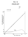
- FIG. 10 shows a portion of the color separation table according to the related art.
- the 10 shows a color separation table 1000 of the neutral tone.
- the ordinate axis denotes an output signal value obtained as a result of the color separation processing, that is, denotes an input value for the gradation correction processing.
- a range of the input signal value is 0 to 255, but a range of the output signal value of the Y component relative to the input signal value is only 0 to 35.
- the value ranging from 0 to 35 is converted into a value ranging from 0 to 2080 by gradation correction processing using the gradation correction table shown in FIG. 9 .
- the output signal values shown in FIG. 10 obtained as results of the color separation processing have only 36 levels, that is, 0 to 35, and the 129 levels, that is, 0 to 128, in this embodiment is far beyond the 36 levels. Therefore, although gradation levels of the Y component for the monochrome image data of the neutral tone are only 36 levels in the related art, they are increased to 129 levels in this embodiment. That is, display capability for the chromatic color is significantly improved.
- the tables are generated with reference to the measured brightness in FIG. 7 , instead of the brightness, luminance, chromaticity, or color density may be used as a reference for generating the tables. Note that this does not mean that the term brightness in the embodiment is simply replaced by the term color density, for example. Each of the terms can be replaced by the other in accordance with their meanings.
- an R component may be added.
- the R component corresponds to a magenta (M) ink and a cyan (C) ink.
- other color tones may be generated by adding a chromatic color to the monochrome image.
- the present invention may be employed in a system configured by a plurality of apparatuses (for example, a host computer, an interface device, a reader device, and a printing device) and may be employed in a single apparatus (for example, a copier and a facsimile device). Furthermore, the present invention may be realized by supplying a storage medium recording program code for implementing the functions described in the above embodiments to a system or an apparatus so that a computer including the system or the apparatus reads and executes the program code stored in the storage medium. In this case, the program code read from the storage medium implements the functions described in the above embodiments, and therefore, the program code and the storage medium storing the program code are included in the present invention.
- the present invention includes a case where an operating system (OS) running on a computer performs part of or entire actual processing and the functions described in the above embodiments are realized.
- the present invention includes a case where the program code read from the storage medium is written in a function expansion card inserted in the computer or a memory provided in a function expansion unit to which the computer is connected.
- a CPU included in the function expansion card or the function expansion unit performs part of or entire actual processing and the functions described in the above embodiments are implemented.
Landscapes
- Engineering & Computer Science (AREA)
- Multimedia (AREA)
- Signal Processing (AREA)
- Facsimile Image Signal Circuits (AREA)
- Color Image Communication Systems (AREA)
- Image Processing (AREA)
Applications Claiming Priority (2)
| Application Number | Priority Date | Filing Date | Title |
|---|---|---|---|
| JP2006346652A JP4823052B2 (ja) | 2006-12-22 | 2006-12-22 | 画像出力方法および画像出力装置 |
| JP2006-346652 | 2006-12-22 |
Publications (2)
| Publication Number | Publication Date |
|---|---|
| US20080151335A1 US20080151335A1 (en) | 2008-06-26 |
| US8098413B2 true US8098413B2 (en) | 2012-01-17 |
Family
ID=39542358
Family Applications (1)
| Application Number | Title | Priority Date | Filing Date |
|---|---|---|---|
| US11/957,096 Expired - Fee Related US8098413B2 (en) | 2006-12-22 | 2007-12-14 | Image output apparatus, image output method, computer program and recording medium |
Country Status (3)
| Country | Link |
|---|---|
| US (1) | US8098413B2 (enExample) |
| JP (1) | JP4823052B2 (enExample) |
| CN (2) | CN102215317B (enExample) |
Families Citing this family (6)
| Publication number | Priority date | Publication date | Assignee | Title |
|---|---|---|---|---|
| JP5526950B2 (ja) | 2009-05-29 | 2014-06-18 | 株式会社リコー | 画像処理装置及び方法、並びに撮像装置 |
| JP5521459B2 (ja) * | 2009-09-16 | 2014-06-11 | 富士ゼロックス株式会社 | 画像処理装置、画像処理プログラム及び画像処理システム |
| US9183475B2 (en) * | 2012-08-21 | 2015-11-10 | Canon Kabushiki Kaisha | Image processing method and apparatus configured for printing a plurality of monochrome images having different parameters |
| US9087289B2 (en) * | 2012-08-21 | 2015-07-21 | Canon Kabushiki Kaisha | Image processing method and apparatus for printing monochrome or color images on a medium |
| CN103481695B (zh) * | 2013-10-14 | 2015-05-27 | 深圳市巨鼎医疗设备有限公司 | 一种医用黑白彩色混合图像的打印方法 |
| CN109760406A (zh) * | 2019-03-09 | 2019-05-17 | 深圳市正鑫源实业有限公司 | 智能凸版印刷放墨量的控制方法及其凸版印刷系统 |
Citations (12)
| Publication number | Priority date | Publication date | Assignee | Title |
|---|---|---|---|---|
| JPH11339032A (ja) | 1998-05-22 | 1999-12-10 | Canon Inc | 画像処理方法及びその装置 |
| US6373595B1 (en) * | 1998-11-30 | 2002-04-16 | Fujitsu Limited | Color data converting method |
| US20020048056A1 (en) * | 2000-10-24 | 2002-04-25 | Fuji Xerox Co., Ltd. | Image processing apparatus |
| US6450606B1 (en) * | 1999-04-19 | 2002-09-17 | Canon Kabushiki Kaisha | Test pattern printing method, information processing apparatus and printing apparatus |
| JP2004094361A (ja) | 2002-08-29 | 2004-03-25 | Seiko Epson Corp | 色変換方法、色変換装置、プログラム、記録媒体 |
| US20040257621A1 (en) * | 2003-04-11 | 2004-12-23 | Hiroshi Ishihara | Method, apparatus, and program for image processing capable of producing high-quality achromatic colored output image, and medium storing the program |
| JP2005065113A (ja) | 2003-08-19 | 2005-03-10 | Seiko Epson Corp | Lutを用いて行う画像処理 |
| US20050073541A1 (en) * | 2002-08-14 | 2005-04-07 | Masahiko Kimura | Image recording apparatus |
| US20050168495A1 (en) * | 2004-01-30 | 2005-08-04 | Canon Kabushiki Kaisha | Method, system and program for forming an image |
| JP2005238835A (ja) | 2004-01-30 | 2005-09-08 | Canon Inc | 画像形成方法、プログラム及び画像形成システム |
| JP2006086708A (ja) | 2004-09-15 | 2006-03-30 | Canon Inc | 画像処理方法及び装置 |
| US20070297667A1 (en) * | 2006-06-16 | 2007-12-27 | Kabushiki Kaisha Toshiba | Image processing apparatus, image processing method and image processing program |
Family Cites Families (4)
| Publication number | Priority date | Publication date | Assignee | Title |
|---|---|---|---|---|
| JP3823424B2 (ja) * | 1996-02-29 | 2006-09-20 | セイコーエプソン株式会社 | 画像処理装置および画像処理方法 |
| JP2005217985A (ja) * | 2004-01-30 | 2005-08-11 | Canon Inc | 画像形成方法及び画像形成システム |
| JP2005286625A (ja) * | 2004-03-29 | 2005-10-13 | Canon Inc | 画像処理装置及びその方法 |
| US20060168495A1 (en) * | 2005-01-25 | 2006-07-27 | Analog Devices, Inc. | Computation of cyclic redundancy check |
-
2006
- 2006-12-22 JP JP2006346652A patent/JP4823052B2/ja not_active Expired - Fee Related
-
2007
- 2007-11-22 CN CN201110197915.2A patent/CN102215317B/zh not_active Expired - Fee Related
- 2007-11-22 CN CN2007101693464A patent/CN101207695B/zh not_active Expired - Fee Related
- 2007-12-14 US US11/957,096 patent/US8098413B2/en not_active Expired - Fee Related
Patent Citations (12)
| Publication number | Priority date | Publication date | Assignee | Title |
|---|---|---|---|---|
| JPH11339032A (ja) | 1998-05-22 | 1999-12-10 | Canon Inc | 画像処理方法及びその装置 |
| US6373595B1 (en) * | 1998-11-30 | 2002-04-16 | Fujitsu Limited | Color data converting method |
| US6450606B1 (en) * | 1999-04-19 | 2002-09-17 | Canon Kabushiki Kaisha | Test pattern printing method, information processing apparatus and printing apparatus |
| US20020048056A1 (en) * | 2000-10-24 | 2002-04-25 | Fuji Xerox Co., Ltd. | Image processing apparatus |
| US20050073541A1 (en) * | 2002-08-14 | 2005-04-07 | Masahiko Kimura | Image recording apparatus |
| JP2004094361A (ja) | 2002-08-29 | 2004-03-25 | Seiko Epson Corp | 色変換方法、色変換装置、プログラム、記録媒体 |
| US20040257621A1 (en) * | 2003-04-11 | 2004-12-23 | Hiroshi Ishihara | Method, apparatus, and program for image processing capable of producing high-quality achromatic colored output image, and medium storing the program |
| JP2005065113A (ja) | 2003-08-19 | 2005-03-10 | Seiko Epson Corp | Lutを用いて行う画像処理 |
| US20050168495A1 (en) * | 2004-01-30 | 2005-08-04 | Canon Kabushiki Kaisha | Method, system and program for forming an image |
| JP2005238835A (ja) | 2004-01-30 | 2005-09-08 | Canon Inc | 画像形成方法、プログラム及び画像形成システム |
| JP2006086708A (ja) | 2004-09-15 | 2006-03-30 | Canon Inc | 画像処理方法及び装置 |
| US20070297667A1 (en) * | 2006-06-16 | 2007-12-27 | Kabushiki Kaisha Toshiba | Image processing apparatus, image processing method and image processing program |
Also Published As
| Publication number | Publication date |
|---|---|
| CN101207695A (zh) | 2008-06-25 |
| CN102215317B (zh) | 2014-04-09 |
| JP2008160475A (ja) | 2008-07-10 |
| US20080151335A1 (en) | 2008-06-26 |
| JP4823052B2 (ja) | 2011-11-24 |
| CN101207695B (zh) | 2011-09-07 |
| CN102215317A (zh) | 2011-10-12 |
Similar Documents
| Publication | Publication Date | Title |
|---|---|---|
| US8310723B2 (en) | Image processing apparatus, printing apparatus, and image processing method | |
| US8059310B2 (en) | Apparatus, method and computer program product for providing output image adjustment for image files | |
| US6474768B1 (en) | Test pattern printing method, information processing apparatus and printing apparatus | |
| US7274487B2 (en) | Color space converting apparatus and method of color space conversion | |
| US7639399B2 (en) | Image processing method | |
| US8098413B2 (en) | Image output apparatus, image output method, computer program and recording medium | |
| JP5335403B2 (ja) | 画像処理装置 | |
| EP1703718B1 (en) | Output image adjustment of image data | |
| US8218206B2 (en) | Color conversion using transformed gamuts | |
| US20080079970A1 (en) | Printing apparatus, printing method, and printing program | |
| US7320510B2 (en) | Image processing method and image processing apparatus | |
| US20040239969A1 (en) | Image processing apparatus and method | |
| JP2020088545A (ja) | 画像形成装置、色校正方法及び色校正プログラム | |
| JP2010098527A (ja) | ルックアップテーブルの作成方法及び印刷装置 | |
| US20090153580A1 (en) | Image processing apparatus and computer readable medium storing program | |
| US8130416B2 (en) | Image forming apparatus, image forming method, computer program, and recording medium | |
| US8625164B2 (en) | Image forming apparatus and method, computer program, and recording medium using density signal and look-up table | |
| JP2007060558A (ja) | 色処理方法およびその装置、並びに、画像処理方法 | |
| JP2006319961A (ja) | 画像処理装置、記録装置および画像処理方法 | |
| JP2622239B2 (ja) | 画像処理方法 | |
| JP2004237617A (ja) | 有彩1次色インクと有彩2次色インクとを含む複数のインク成分への分版処理 | |
| JP2013115713A (ja) | 色変換テーブルの作成方法 | |
| JP2007274205A (ja) | 画像形成装置及び画質調整方法 | |
| JP2004299171A (ja) | 有彩1次色インクと有彩2次色インクとを含む複数のインク成分への分版処理 | |
| JP2004209900A (ja) | 色再現範囲の拡張を考慮した分版処理 |
Legal Events
| Date | Code | Title | Description |
|---|---|---|---|
| AS | Assignment |
Owner name: CANON KABUSHIKI KAISHA, JAPAN Free format text: ASSIGNMENT OF ASSIGNORS INTEREST;ASSIGNOR:SUMI, NAOKI;REEL/FRAME:020344/0625 Effective date: 20071023 |
|
| STCF | Information on status: patent grant |
Free format text: PATENTED CASE |
|
| FPAY | Fee payment |
Year of fee payment: 4 |
|
| FEPP | Fee payment procedure |
Free format text: MAINTENANCE FEE REMINDER MAILED (ORIGINAL EVENT CODE: REM.); ENTITY STATUS OF PATENT OWNER: LARGE ENTITY |
|
| LAPS | Lapse for failure to pay maintenance fees |
Free format text: PATENT EXPIRED FOR FAILURE TO PAY MAINTENANCE FEES (ORIGINAL EVENT CODE: EXP.); ENTITY STATUS OF PATENT OWNER: LARGE ENTITY |
|
| STCH | Information on status: patent discontinuation |
Free format text: PATENT EXPIRED DUE TO NONPAYMENT OF MAINTENANCE FEES UNDER 37 CFR 1.362 |
|
| FP | Lapsed due to failure to pay maintenance fee |
Effective date: 20200117 |