US8096431B2 - Combination yoke and elastomeric draft gear having a friction mechanism - Google Patents
Combination yoke and elastomeric draft gear having a friction mechanism Download PDFInfo
- Publication number
- US8096431B2 US8096431B2 US12/150,808 US15080808A US8096431B2 US 8096431 B2 US8096431 B2 US 8096431B2 US 15080808 A US15080808 A US 15080808A US 8096431 B2 US8096431 B2 US 8096431B2
- Authority
- US
- United States
- Prior art keywords
- yoke
- gear assembly
- draft gear
- pair
- friction
- Prior art date
- Legal status (The legal status is an assumption and is not a legal conclusion. Google has not performed a legal analysis and makes no representation as to the accuracy of the status listed.)
- Expired - Fee Related, expires
Links
Images


Classifications
-
- B—PERFORMING OPERATIONS; TRANSPORTING
- B21—MECHANICAL METAL-WORKING WITHOUT ESSENTIALLY REMOVING MATERIAL; PUNCHING METAL
- B21F—WORKING OR PROCESSING OF METAL WIRE
- B21F35/00—Making springs from wire
-
- B—PERFORMING OPERATIONS; TRANSPORTING
- B61—RAILWAYS
- B61G—COUPLINGS; DRAUGHT AND BUFFING APPLIANCES
- B61G9/00—Draw-gear
- B61G9/04—Draw-gear combined with buffing appliances
- B61G9/06—Draw-gear combined with buffing appliances with rubber springs
-
- B—PERFORMING OPERATIONS; TRANSPORTING
- B61—RAILWAYS
- B61G—COUPLINGS; DRAUGHT AND BUFFING APPLIANCES
- B61G9/00—Draw-gear
- B61G9/04—Draw-gear combined with buffing appliances
- B61G9/10—Draw-gear combined with buffing appliances with separate mechanical friction shock-absorbers
-
- B—PERFORMING OPERATIONS; TRANSPORTING
- B61—RAILWAYS
- B61G—COUPLINGS; DRAUGHT AND BUFFING APPLIANCES
- B61G9/00—Draw-gear
- B61G9/20—Details; Accessories
- B61G9/22—Supporting framework, e.g. cradles; Spring housings
-
- B—PERFORMING OPERATIONS; TRANSPORTING
- B29—WORKING OF PLASTICS; WORKING OF SUBSTANCES IN A PLASTIC STATE IN GENERAL
- B29C—SHAPING OR JOINING OF PLASTICS; SHAPING OF MATERIAL IN A PLASTIC STATE, NOT OTHERWISE PROVIDED FOR; AFTER-TREATMENT OF THE SHAPED PRODUCTS, e.g. REPAIRING
- B29C43/00—Compression moulding, i.e. applying external pressure to flow the moulding material; Apparatus therefor
- B29C43/32—Component parts, details or accessories; Auxiliary operations
- B29C43/36—Moulds for making articles of definite length, i.e. discrete articles
- B29C43/361—Moulds for making articles of definite length, i.e. discrete articles with pressing members independently movable of the parts for opening or closing the mould, e.g. movable pistons
- B29C2043/3613—Moulds for making articles of definite length, i.e. discrete articles with pressing members independently movable of the parts for opening or closing the mould, e.g. movable pistons applying pressure locally
-
- B—PERFORMING OPERATIONS; TRANSPORTING
- B29—WORKING OF PLASTICS; WORKING OF SUBSTANCES IN A PLASTIC STATE IN GENERAL
- B29C—SHAPING OR JOINING OF PLASTICS; SHAPING OF MATERIAL IN A PLASTIC STATE, NOT OTHERWISE PROVIDED FOR; AFTER-TREATMENT OF THE SHAPED PRODUCTS, e.g. REPAIRING
- B29C43/00—Compression moulding, i.e. applying external pressure to flow the moulding material; Apparatus therefor
- B29C43/32—Component parts, details or accessories; Auxiliary operations
- B29C43/36—Moulds for making articles of definite length, i.e. discrete articles
- B29C2043/3665—Moulds for making articles of definite length, i.e. discrete articles cores or inserts, e.g. pins, mandrels, sliders
-
- B—PERFORMING OPERATIONS; TRANSPORTING
- B29—WORKING OF PLASTICS; WORKING OF SUBSTANCES IN A PLASTIC STATE IN GENERAL
- B29L—INDEXING SCHEME ASSOCIATED WITH SUBCLASS B29C, RELATING TO PARTICULAR ARTICLES
- B29L2031/00—Other particular articles
- B29L2031/721—Vibration dampening equipment, e.g. shock absorbers
-
- Y—GENERAL TAGGING OF NEW TECHNOLOGICAL DEVELOPMENTS; GENERAL TAGGING OF CROSS-SECTIONAL TECHNOLOGIES SPANNING OVER SEVERAL SECTIONS OF THE IPC; TECHNICAL SUBJECTS COVERED BY FORMER USPC CROSS-REFERENCE ART COLLECTIONS [XRACs] AND DIGESTS
- Y10—TECHNICAL SUBJECTS COVERED BY FORMER USPC
- Y10T—TECHNICAL SUBJECTS COVERED BY FORMER US CLASSIFICATION
- Y10T29/00—Metal working
- Y10T29/49—Method of mechanical manufacture
- Y10T29/49609—Spring making
- Y10T29/49611—Spring making for vehicle or clutch
-
- Y—GENERAL TAGGING OF NEW TECHNOLOGICAL DEVELOPMENTS; GENERAL TAGGING OF CROSS-SECTIONAL TECHNOLOGIES SPANNING OVER SEVERAL SECTIONS OF THE IPC; TECHNICAL SUBJECTS COVERED BY FORMER USPC CROSS-REFERENCE ART COLLECTIONS [XRACs] AND DIGESTS
- Y10—TECHNICAL SUBJECTS COVERED BY FORMER USPC
- Y10T—TECHNICAL SUBJECTS COVERED BY FORMER US CLASSIFICATION
- Y10T29/00—Metal working
- Y10T29/49—Method of mechanical manufacture
- Y10T29/49609—Spring making
- Y10T29/49615—Resilient shock or vibration absorber utility
-
- Y—GENERAL TAGGING OF NEW TECHNOLOGICAL DEVELOPMENTS; GENERAL TAGGING OF CROSS-SECTIONAL TECHNOLOGIES SPANNING OVER SEVERAL SECTIONS OF THE IPC; TECHNICAL SUBJECTS COVERED BY FORMER USPC CROSS-REFERENCE ART COLLECTIONS [XRACs] AND DIGESTS
- Y10—TECHNICAL SUBJECTS COVERED BY FORMER USPC
- Y10T—TECHNICAL SUBJECTS COVERED BY FORMER US CLASSIFICATION
- Y10T29/00—Metal working
- Y10T29/49—Method of mechanical manufacture
- Y10T29/49826—Assembling or joining
- Y10T29/49833—Punching, piercing or reaming part by surface of second part
- Y10T29/49835—Punching, piercing or reaming part by surface of second part with shaping
- Y10T29/49837—Punching, piercing or reaming part by surface of second part with shaping of first part
Definitions
- the present invention relates, in general, to draft gear assemblies for railway vehicles and, more particularly, this invention relates to a draft gear assembly installed within the yoke of the railway vehicle and having at least one compressible elastomeric spring and a cooperating friction mechanism.
- Draft gear assemblies for cushioning buff and draft shocks encountered during make-up and operation of a railway vehicle are well known in the art to include a housing having a closed end and an open end, a compressible member disposed within the closed end and a friction mechanism disposed within the open end. Lately, various railroads and operators of railway vehicles have been seeking both the increased loading of the railway vehicles and capability of the draft gear assembly to withstand higher dynamic impact loads.
- U.S. Pat. No. 6,446,820 issued to Barker et al. discloses one type of such effort, wherein the draft gear assembly which has a yoke, a coupler follower, a rear follower, a front resilient member and a back resilient member.
- the yoke has top and bottom stops.
- the coupler follower is biased against the yoke top and bottom stops.
- the draft gear assembly also includes a center rod that extends through the yoke, through the back resilient member and through the rear follower.
- the rear end of the center rod is threaded and receives a threaded fastener to retain the rear follower and the back resilient member.
- the center rod is not sufficient to maintain axial alignment of the back resilient member resulting in loss of lateral stability of pads and plates and further resulting in decreased performance and decreased reliability of the draft gear assembly. It has been further found that this draft gear assembly does not resist overcompression of the back resilient member further resulting in decreased reliability and increased maintenance costs.
- the invention provides a draft gear assembly for cushioning buff and draft shocks encountered during make-up and operation of a railway vehicle.
- the draft gear assembly includes at least one compressible resilient spring member which is mounted within a yoke of such railway vehicle coaxial with a longitudinal axis thereof.
- the yoke is mounted within a hollow center sill of a railway vehicle body.
- a friction mechanism is also provided and is disposed in abutting engagement with one end of the at least one compressible resilient spring member. The friction mechanism is further disposed in abutting engagement with at least one predetermined portion of the yoke.
- the draft gear assembly includes an elongated yoke removably mountable within a hollow center sill of a railway vehicle body.
- the yoke has a yoke head which is adapted to connect to an end of a coupler shank, a butt end axially opposing the yoke head, and a pair of elongated, substantially parallel spaced-apart top and bottom strap members.
- Each top or bottom strap member has an inner surface, an outer surface, a front end and a rear end. The rear end of each strap member is joined to the butt end of the yoke and the front end of each strap member is joined to the yoke head.
- a rear follower is positioned intermediate the top and the bottom strap members transversely to a longitudinal central axis of the yoke.
- the rear follower is sized to abut a draft gear seat formed within the butt end of the yoke and a pair of rear stops secured to the center sill when the draft gear assembly is in a position to cushion the buff shocks.
- a front coupler follower is also positioned intermediate the top and the bottom strap members transversely to the central axis of the yoke.
- the front coupler follower is sized to abut a pair of front stops formed in a striker casing engaging the center sill when the draft gear assembly is in a position to cushion the draft shocks.
- a compressible resilient spring member is mounted within the yoke concentric with the longitudinal axis thereof.
- the compressible resilient spring member has a rear end thereof abutting an inner surface of the rear follower.
- a friction mechanism is disposed in abutting engagement between a front end of the compressible resilient spring member and an inner surface of the front coupler follower.
- the draft gear assembly includes an elongated yoke removably mountable within a hollow center sill of a railway vehicle body.
- the yoke has a yoke head which is adapted to connect to an end of a coupler shank, a butt end axially opposing the yoke head, and a pair of elongated, substantially parallel spaced-apart top and bottom strap members.
- Each top or bottom member has an inner surface, an outer surface, a front end and a rear end. The rear end of each strap member is joined to the butt end of the yoke and the front end of each strap member being is joined to the yoke head.
- a rear follower is positioned intermediate the top and the bottom strap members transversely to a longitudinal central axis of the yoke.
- the rear follower is sized to abut a draft gear seat formed within the butt end of the yoke and a pair of rear stops secured to the center sill when the draft gear assembly is in a position to cushion the buff shocks.
- a front coupler follower is also positioned intermediate the top and the bottom strap members transversely to the central axis of the yoke.
- the front coupler follower is sized to abut a pair of front stops formed in a striker casing engaging the center sill when the draft gear assembly is in a position to cushion the draft shocks.
- a first compressible resilient spring member is mounted within the yoke coaxial with the longitudinal axis thereof, the first compressible resilient spring member has a rear end thereof abutting an inner surface of the rear follower.
- a second compressible resilient spring member is also mounted within the yoke coaxial with the longitudinal axis thereof. The second compressible resilient spring member has a front end thereof abutting an inner surface of the front coupler follower.
- a friction mechanism is disposed in abutting engagement between a front end of the first resilient spring member and a rear end of the second compressible resilient spring member.
- Another object of the present invention is to provide a draft gear assembly that employs a combination of a compressible elastomeric spring and a friction mechanism, both mounted within the yoke of the railway vehicle between the rear and front followers.
- Yet another object of the present invention is to provide a draft gear assembly that will at least meet and even exceed all AAR requirements, presently in force, even though such draft gear assembly is lighter in weight.
- a further object of the present invention is to provide a draft gear assembly that employs a combination of a compressible elastomeric spring and a friction mechanism disposed in abutting relationship with the yoke of such railway vehicle for maintaining axial alignment of the compressible elastomeric spring during use of the draft gear assembly.
- An additional object of the present invention is to provide a draft gear assembly that employs a pair of compressible elastomeric springs mounted axially within the yoke of the railway car between the front coupler follower and the rear follower and which are separated by a friction mechanism.
- FIG. 1 is an isometric view illustrating a draft gear assembly which is constructed in accordance with one embodiment of the present invention
- FIG. 2 is an isometric view illustrating a draft gear assembly which is constructed in accordance with another embodiment of the present invention
- FIG. 3 is a cross-sectional elevation view of the draft gear assembly of FIG. 2 ;
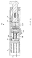
- FIG. 4 is an enlarged partial cross-sectional elevation view of the draft gear assembly of FIG. 3 , particularly illustrating a friction mechanism constructed in accordance with a presently preferred embodiment of the present invention
- FIG. 5 is a cross-sectional elevation view of a draft gear assembly which is constructed in accordance with yet another embodiment of the present invention.
- FIG. 6 is a cross-sectional planar view of a draft gear assembly which is constructed in accordance with a further embodiment of the present invention.
- railway vehicle applies but is not limited to passenger railcar, freight railcar, locomotive and the like railway vehicles.
- FIGS. 1 through 6 The best mode for carrying out the invention is presented in terms of its various embodiments, herein depicted within FIGS. 1 through 6 .
- the invention is not limited to the described embodiments, and a person skilled in the art will appreciate that many other embodiments of the invention are possible without deviating from the basic concept of the invention and that any such work around will also fall under scope of this invention.
- It is envisioned that other styles and configurations of the present invention can be easily incorporated into the teachings of the present invention, and only several particular configurations shall be shown and described for purposes of clarity and disclosure and not by way of limitation of scope.
- the present invention provides a draft gear assembly for cushioning both buff and draft impact forces (shocks) being applied to a center sill member of a railway vehicle (not shown) during make-up of a train consist and in-track operation of such train consist.
- the draft gear assembly is used in combination with a conventional yoke, generally designated as 20 , and generally mounted between a rear follower block, generally designated as 50 , and a front coupler follower block, generally designated as 60 .
- the yoke 20 is removably mounted within the hollow center sill 2 of a railway vehicle body (not shown).
- the yoke 20 is illustrated as a conventional yoke for standard AAR E-type couplers, for example as disclosed in U.S. Pat. No. 4,095,065 issued to Elliott et al. and whose teachings are incorporated into this document by reference thereto.
- the yoke 20 includes a yoke head 22 having a pair of keyslot walls 24 .
- a butt end 26 of the yoke 20 axially opposes the yoke head 22 and has a conventional draft gear seat 28 formed therein.
- There is an elongated top strap member 30 which is disposed, in a conventional manner, between the yoke head 22 and the butt end 26 .
- the top strap member 30 has a horizontally disposed flat inner surface 32 , a horizontally disposed outer surface 34 and a pair of vertically disposed side edges 36 .
- the bottom strap member 40 has a horizontally disposed flat inner surface 42 , a horizontally disposed outer surface 44 and a pair of vertically disposed side edges 46 .
- the rear follower 50 is positioned intermediate the top and the bottom strap members, 30 and 40 respectively, and transversely to a longitudinal central axis 21 of the yoke 20 .
- the rear follower 50 is sized to abut a seat 28 of the yoke 20 and a pair of rear stops 3 the draft gear assembly 70 is in a position to cushion the buff shocks.
- the rear stops 3 are secured to inner wall surfaces 4 of the center sill 2 , as best shown in FIGS. 3 , 5 and 6 .
- the front coupler follower 60 is also positioned intermediate the top and the bottom strap members, 30 and 40 respectively and transversely to the central axis 21 of the yoke 20 .
- the front coupler follower 60 is sized to abut a pair of front stops 8 , best shown in FIG. 5 , which are formed on a rear portion of the striker casing 5 engaging the center sill 2 when the draft gear assembly 70 is in a position to cushion the draft shocks.
- the front coupler follower 60 further abuts the shank 12 of the coupler 10 in a conventional manner.
- the draft gear assembly of the present invention essentially includes at least one resilient cushioning member which is centrally mounted within the yoke 20 in combination with a friction mechanism, generally designated as 220 .
- the longitudinal axis of the at least one resilient cushioning member is aligned with a longitudinal central axis 21 of the yoke 20 .
- Such resilient cushioning member is presently preferred for such resilient cushioning member to be constructed substantially identical, except for length, to the spring 102 disclosed in a co-pending U.S. Ser. No. 12/150,809 entitled “Compressible Elastomeric Spring” filled concurrently therewith. It is further presently preferred to provide the plates as disclosed in the co-pending U.S. Ser. No. 12/150,926 “Plate For A Compressible Elastomeric Spring” and provide the elastomeric pads as disclosed in the co-pending U.S. Ser. No. 12/150,928entitled “Elastomeric Pad For A Compressible Elastomeric Spring”.
- the compressible elastomeric spring includes the predetermined plurality of pads 110 and separator plate like members 190 which form in combination a multi-tiered stack having a predetermined initial height, and whereby each of the predetermined plurality of pads 110 compresses and extends along the central axis 21 of the yoke 20 causing movement of each of the predetermined plurality of separator plate like members 190 along the central axis 21 during cushioning of the buff and draft dynamic impact forces (shocks).
- a draft gear assembly generally designated as 76
- a draft gear assembly includes a single compressible elastomeric spring 102 e mounted axially intermediate the rear coupler 50 and the front follower coupler 60 for absorbing and cushioning buff and draft dynamic impact forces (shocks) applied to the draft gear assembly 76 through the coupler shank 12 .
- the draft gear assembly 76 further includes the friction mechanism 220 which can be better seen in an enlarged view of FIG. 4 .
- the friction mechanism 220 engages the front end of the spring 102 e and is positioned for axial movement within the yoke 20 .
- the friction mechanism 220 includes a first friction member 230 having a first horizontally disposed planar surface 232 , a second horizontally disposed opposed surface 234 , and a pair of axially opposed and vertically disposed ends 236 .
- Each end 236 has a tapered friction portion 238 which tapers downwardly and inwardly when the first friction member 230 in installed within the yoke 20 .
- a second friction member 240 is also provided and is vertically spaced from the first friction member 230 .
- the second friction member 240 has a first horizontally disposed planar surface 242 , a second opposed horizontally disposed surface 244 , and a pair of axially opposed and vertically disposed ends 246 .
- Each end 246 has a tapered friction portion 248 which tapers upwardly and inwardly when the second friction member 240 is installed within the yoke 20 .
- the second friction member 240 is substantially identical to the first friction member 230 .
- Each tapered friction portion 256 matches and frictionally engages a respective tapered portion 238 , 248 formed in a respective end of the first friction member 230 and the second friction member 240 .
- the first planar surface 232 of the first friction member 230 abuts and axially moves about the inner surface 32 of the top strap member 30 of the yoke 20 .
- the first friction member 230 includes a pair of spaced apart flanges 239 which extend outwardly in a vertical direction from each end of the first planar surface 232 and engage side edges 36 of the top strap member 30 for guiding axial movement of the friction mechanism 220 and the elastomeric compressible spring 102 e as well as for preventing lateral movement thereof.
- the flanges 239 are formed integral with the first friction member 230 .
- both flanges 239 may be secured to the first planar surface 232 with the use of conventional threaded fasteners 239 a by providing apertures 239 b formed vertically through such flange 239 and a complimentary threaded aperture or bore (not shown) formed vertically through or within the first planar surface 232 .
- first planar surface 242 of the second friction member 240 abuts and axially moves about the inner surface 42 of the bottom strap member 40 of the yoke 20 .
- Pair of spaced apart flanges 249 at least one of secured to and formed integral with the first planar surface 242 extend outwardly in a vertical direction from each end of the first planar surface 242 and also engage side edges 46 of the bottom strap member 40 for guiding axial movement of the friction mechanism 220 and the elastomeric compressible spring 102 e.
- the friction mechanism 220 is shown as positioned adjacent the front end 32 of the yoke 30 in abutting relationship with a front end of the compressible elastomeric spring 102 e .
- the friction mechanism 220 multiplies the resisting force of the compressible elastomeric spring 102 e , by way of frictional engagement of the tapered friction portions 238 and 248 with respective matching tapered friction portions 255 , thus increasing energy absorption of the draft gear assembly 76 during cushioning of the buff and draft dynamic impact forces (shocks).
- the spring 102 e may be simply positioned between the rear follower 50 and the friction mechanism 220 in a conventional pre-compressed manner. If desired for a particular application, it is contemplated by the present invention that the draft gear assembly 76 may include a locating means for locating front end of the spring 102 e on the inwardly positioned wedge 250 and for locating the rear end of the spring 102 e on the inner surface 52 of the rear follower 50 in a manner generally identical of locating end of the spring on the face of the central plate 200 in FIGS. 5-6 of the co-pending U.S. Ser. No.
- each face surface of the center plate 200 will be replaced by the surface 252 of each wedge 250 or by the inner surface 52 of the rear coupler 50 .
- the detail description of such locating means will be omitted in this document for the sake of brevity.
- each bottom and/or top horizontally disposed edge of the plate like members 150 , 190 may be positioned in abutting engagement with respective inner surfaces 32 , 42 of the yoke 20 .
- a bottom and/or top horizontally disposed edge of at least one the plate like members 190 may be provided with flanges 199 positioned in abutting engagement with the side edges 36 , 46 of the yoke 30 .
- Such flanges 199 disposed on the bottom edge of the plate like members 190 are best shown in FIGS. 1 and 2 .
- tapered portions 256 of the wedge 250 may be integrally formed with the inner surface 62 of the front follower 60 by a casting method or the wedge 250 may be rigidly secured to the inner surface 62 , for example, by a welding method.
- such pre-shortening means may include an aperture 270 formed through at least one of the top strap member 30 and the bottom strap member 40 of the yoke 20 and a complimentary bore 272 which is formed in at least one of the first planar surface 232 of the first planar surface 242 and shown in FIG. 4 as being formed in the first friction member 230 .
- a pin 274 is passed through the aperture 270 and is received within the bore 272 .
- the pin 272 is made from a conventional material enabling shearing of the pin 274 during the first application of the dynamic impact load. It is also within the scope of the present invention to provide other means of pre-shortening the draft gear assembly 76 .
- FIGS. 2-4 illustrate another embodiment of the present invention, wherein a draft gear assembly, generally designated as 78 , is shown.
- the draft gear assembly 78 includes a pair of compressible springs 102 f and the friction mechanism 220 which is positioned intermediate the inner ends of each spring 102 f .
- the friction mechanism 220 will increase energy absorption of the draft gear assembly 78 during both buff and draft dynamic impact forces (shocks) conditions.
- each spring 102 f with the first surface 252 of a respective one of the pair of wedges 250 will be achieved generally identically to interfacing the center plate 200 in the draft gear assembly 72 of FIGS. 5-6 of the co-pending U.S. Ser. No. 12/150,777 entitled “Combination Yoke and Elastomeric Draft Gear”, except that each face surface of the center plate 200 will be replaced by the first surface 252 of each wedge 250 .
- the above pre-shortening means described in combination with the draft gear assembly 76 of FIG. 1 may be employed in this embodiment, particularly, when the draft gear assembly 78 is installed into the yoke 20 .
- the pin 274 may be arranged to engage a bore (not shown) formed in the front follower 60 .
- FIG. 5 therein is illustrated yet another embodiment of the present invention, wherein the draft gear assembly, generally designated as 80 , which is constructed generally identical to the draft gear assembly 78 of FIG. 2 except that the friction mechanism 220 is rotated ninety (90) degrees so that the first planar surface 232 , 242 of each of the first and second friction members, 230 and 240 respectively, abut and slidingly move about a respective inner vertical surface 4 of the center sill 2 for providing axial guidance and for maintaining lateral stability of the compressible elastomeric springs 102 f.
- the draft gear assembly generally designated as 80
- the friction mechanism 220 is rotated ninety (90) degrees so that the first planar surface 232 , 242 of each of the first and second friction members, 230 and 240 respectively, abut and slidingly move about a respective inner vertical surface 4 of the center sill 2 for providing axial guidance and for maintaining lateral stability of the compressible elastomeric springs 102 f.
- a draft gear assembly generally designated as 82 , is shown and includes one coiled spring 108 which can be manufactured from steel or any other suitable material.
- a first end of the coiled spring 108 is received within a first spring seat 262 formed in an inner one of the pair of vertically positioned wedges 250 and having a second end thereof received within a second spring seat 264 formed in the rear follower 50 .
- first spring seat 262 and second spring seat 264 may be a simple bore having each of a predetermined diameter and a predetermined depth. If a pair of axially aligned coil springs 108 are employed, identical seats 262 , 264 will be formed in the opposed wedge 250 and the surface of the front coupler 60 . When it is desirable to replace each spring 108 with a plurality of smaller diameter springs, a plurality of complimentary seats will be provided in the rear coupler 50 , front coupler 60 and the wedges 250 of the friction mechanism 220 . It will be understood, that the spring 108 may be simply installed in the draft gear 76 of FIG. 1 .
- a predetermined plurality of springs 100 disclosed in the co-pending U.S. Ser. No. 12/150,809entitled “Compressible Elastomeric Spring” may be employed in the draft gear assemblies of FIGS. 1-6 .
Landscapes
- Engineering & Computer Science (AREA)
- Mechanical Engineering (AREA)
- Springs (AREA)
- Vibration Dampers (AREA)
- Casting Or Compression Moulding Of Plastics Or The Like (AREA)
- Gears, Cams (AREA)
- Vibration Prevention Devices (AREA)
- Gasket Seals (AREA)
Abstract
Description
Claims (22)
Priority Applications (1)
| Application Number | Priority Date | Filing Date | Title |
|---|---|---|---|
| US12/150,808 US8096431B2 (en) | 2007-05-01 | 2008-05-01 | Combination yoke and elastomeric draft gear having a friction mechanism |
Applications Claiming Priority (2)
| Application Number | Priority Date | Filing Date | Title |
|---|---|---|---|
| US92698707P | 2007-05-01 | 2007-05-01 | |
| US12/150,808 US8096431B2 (en) | 2007-05-01 | 2008-05-01 | Combination yoke and elastomeric draft gear having a friction mechanism |
Publications (2)
| Publication Number | Publication Date |
|---|---|
| US20080272079A1 US20080272079A1 (en) | 2008-11-06 |
| US8096431B2 true US8096431B2 (en) | 2012-01-17 |
Family
ID=39596447
Family Applications (9)
| Application Number | Title | Priority Date | Filing Date |
|---|---|---|---|
| US12/150,927 Expired - Fee Related US8096432B2 (en) | 2007-05-01 | 2008-05-01 | Elastomeric draft gear having a housing |
| US12/150,925 Active 2029-01-23 US7981348B2 (en) | 2007-05-01 | 2008-05-01 | Method of making elastomeric pad for a compressible elastomeric spring |
| US12/150,929 Expired - Fee Related US8336209B2 (en) | 2007-05-01 | 2008-05-01 | Method of making compressible elastomeric spring |
| US12/150,809 Active 2030-11-18 US8783670B2 (en) | 2007-05-01 | 2008-05-01 | Compressible elastomeric spring |
| US12/150,926 Expired - Fee Related US7857273B2 (en) | 2007-05-01 | 2008-05-01 | Plate for a compressible elastomeric spring |
| US12/150,808 Expired - Fee Related US8096431B2 (en) | 2007-05-01 | 2008-05-01 | Combination yoke and elastomeric draft gear having a friction mechanism |
| US12/150,777 Active 2028-08-27 US8136683B2 (en) | 2007-05-01 | 2008-05-01 | Combination yoke and elastomeric draft gear |
| US12/150,928 Active 2030-04-17 US8465009B2 (en) | 2007-05-01 | 2008-05-01 | Elastomeric pad for a compressible elastomeric spring |
| US13/669,901 Active US8701290B2 (en) | 2007-05-01 | 2012-11-06 | Method of making compressible elastomeric spring |
Family Applications Before (5)
| Application Number | Title | Priority Date | Filing Date |
|---|---|---|---|
| US12/150,927 Expired - Fee Related US8096432B2 (en) | 2007-05-01 | 2008-05-01 | Elastomeric draft gear having a housing |
| US12/150,925 Active 2029-01-23 US7981348B2 (en) | 2007-05-01 | 2008-05-01 | Method of making elastomeric pad for a compressible elastomeric spring |
| US12/150,929 Expired - Fee Related US8336209B2 (en) | 2007-05-01 | 2008-05-01 | Method of making compressible elastomeric spring |
| US12/150,809 Active 2030-11-18 US8783670B2 (en) | 2007-05-01 | 2008-05-01 | Compressible elastomeric spring |
| US12/150,926 Expired - Fee Related US7857273B2 (en) | 2007-05-01 | 2008-05-01 | Plate for a compressible elastomeric spring |
Family Applications After (3)
| Application Number | Title | Priority Date | Filing Date |
|---|---|---|---|
| US12/150,777 Active 2028-08-27 US8136683B2 (en) | 2007-05-01 | 2008-05-01 | Combination yoke and elastomeric draft gear |
| US12/150,928 Active 2030-04-17 US8465009B2 (en) | 2007-05-01 | 2008-05-01 | Elastomeric pad for a compressible elastomeric spring |
| US13/669,901 Active US8701290B2 (en) | 2007-05-01 | 2012-11-06 | Method of making compressible elastomeric spring |
Country Status (11)
| Country | Link |
|---|---|
| US (9) | US8096432B2 (en) |
| EP (8) | EP2150722A1 (en) |
| KR (8) | KR20100022965A (en) |
| CN (8) | CN101801758B (en) |
| AU (7) | AU2008246063B2 (en) |
| CA (8) | CA2684343C (en) |
| MX (8) | MX2009011719A (en) |
| RU (8) | RU2491197C2 (en) |
| UA (8) | UA100854C2 (en) |
| WO (8) | WO2008134084A1 (en) |
| ZA (1) | ZA200906746B (en) |
Cited By (2)
| Publication number | Priority date | Publication date | Assignee | Title |
|---|---|---|---|---|
| US9701323B2 (en) | 2015-04-06 | 2017-07-11 | Bedloe Industries Llc | Railcar coupler |
| RU236817U1 (en) * | 2025-06-05 | 2025-08-22 | Акционерное общество "Рузаевский завод химического машиностроения" (АО "Рузхиммаш") | Traction clamp |
Families Citing this family (50)
| Publication number | Priority date | Publication date | Assignee | Title |
|---|---|---|---|---|
| US8096432B2 (en) * | 2007-05-01 | 2012-01-17 | Wabtec Holding Corp | Elastomeric draft gear having a housing |
| US8544662B2 (en) * | 2008-05-22 | 2013-10-01 | Bedloe Industries Llc | Central datum feature on railroad coupler body and corresponding gauges |
| MX373677B (en) * | 2008-05-22 | 2020-06-08 | Bedloe Ind Llc | CENTRAL BASE POINT FEATURE ON A RAILROAD COUPLER BODY AND CORRESPONDING GAUGES. |
| US8196912B2 (en) * | 2008-09-10 | 2012-06-12 | Miner Enterprises, Inc. | Railcar elastomeric spring |
| RU2446068C2 (en) * | 2010-06-18 | 2012-03-27 | Открытое акционерное общество "Авиаагрегат" | Absorbing apparatus |
| CA2746210C (en) * | 2010-07-14 | 2017-07-11 | Andre Senecal | Device for preventing overdrawing of winch hook |
| US8714377B2 (en) * | 2011-02-04 | 2014-05-06 | Wabtec Holding Corp. | Energy absorbing coupler |
| US8607998B2 (en) | 2011-03-31 | 2013-12-17 | Mcconway & Torley Llc | Railway car yoke |
| MX338508B (en) * | 2011-03-31 | 2016-04-15 | Mcconway & Torley Llc | Railway car yoke. |
| US8672151B2 (en) * | 2011-09-15 | 2014-03-18 | Wabtec Corp | Elastomeric draft gear for a railcar |
| US9562582B2 (en) * | 2011-09-15 | 2017-02-07 | Wabtec Holding Corp. | Compressible elastomeric spring |
| CN102431205A (en) * | 2011-12-13 | 2012-05-02 | 北京隆轩橡塑有限公司 | Precompression device for polymer compression spring |
| US8991799B1 (en) * | 2012-04-19 | 2015-03-31 | J. Thomas Ellis | Shock absorbing assembly for a hydraulic catwalk |
| CN102678805B (en) * | 2012-05-31 | 2014-04-02 | 中南大学 | Impact energy absorbing device of diaphragm bolt type tandem porous solid elements |
| CN102691742B (en) * | 2012-05-31 | 2014-09-24 | 中南大学 | An impact energy-absorbing device of diaphragm meshing type porous solid elements in series |
| ITRM20120542A1 (en) * | 2012-11-07 | 2014-05-08 | Cofren Srl | SHOE FOR DISC BRAKES FOR RAILWAY VEHICLES |
| US9598092B2 (en) | 2014-11-13 | 2017-03-21 | Miner Enterprises, Inc. | Railcar energy absorption/coupling system |
| US10384696B2 (en) | 2014-11-13 | 2019-08-20 | Miner Enterprises, Inc. | Railroad car coupling system |
| USD781179S1 (en) | 2015-04-28 | 2017-03-14 | Miner Enterprises, Inc. | Railcar cushioning assembly follower |
| CN105270434B (en) * | 2015-11-03 | 2017-11-03 | 大连交通大学 | Polygonal shell polymer elastic element and metal friction element combined buffer |
| EA033029B1 (en) * | 2015-12-21 | 2019-08-30 | Олег Николаевич ГОЛОВАЧ | Friction shock absorber |
| RU2646764C2 (en) * | 2016-01-11 | 2018-03-07 | Олег Николаевич ГОЛОВАЧ | Friction shock absorber |
| US9868453B2 (en) | 2016-05-20 | 2018-01-16 | O-Ring Sales & Service, Inc. | Railcar end unit |
| RU169847U1 (en) * | 2016-08-22 | 2017-04-04 | Алексей Петрович Болдырев | Compressible elastic element |
| US10189488B2 (en) * | 2016-09-02 | 2019-01-29 | Amsted Rail Company, Inc. | Railway freight car draft gear assembly |
| RU177076U1 (en) * | 2016-12-01 | 2018-02-07 | ФЕДЕРАЛЬНОЕ ГОСУДАРСТВЕННОЕ БЮДЖЕТНОЕ ОБРАЗОВАТЕЛЬНОЕ УЧРЕЖДЕНИЕ ВЫСШЕГО ОБРАЗОВАНИЯ "Брянский государственный технический университет" | Friction Absorbing Vehicle Auto Coupler |
| USD857554S1 (en) | 2017-02-10 | 2019-08-27 | Miner Enterprises, Inc. | H-shaped railcar follower |
| RU184139U1 (en) * | 2017-06-06 | 2018-10-16 | Олег Николаевич ГОЛОВАЧ | Friction damper |
| RU2670353C1 (en) * | 2017-06-26 | 2018-10-22 | Александр Александрович Андреев | Absorbing apparatus |
| US11208165B2 (en) | 2017-08-02 | 2021-12-28 | Joy Global Surface Mining Inc | Passive track tensioning system |
| RU184340U1 (en) * | 2017-08-22 | 2018-10-22 | Олег Николаевич ГОЛОВАЧ | Damping part of the device for energy absorption |
| RU2674215C1 (en) * | 2017-09-12 | 2018-12-05 | Борис Григорьевич Кеглин | Friction-polymer shock absorber |
| CN107631889B (en) * | 2017-09-20 | 2020-01-10 | 中车唐山机车车辆有限公司 | Rail vehicle parking brake performance test system and test method |
| US10870123B2 (en) | 2018-01-03 | 2020-12-22 | Silgan Dispensing Systems Corporation | Dispensing pump with locking structures and methods of using the same |
| US10473176B2 (en) | 2018-01-03 | 2019-11-12 | Silgan Dispensing Systems Corporation | Compression spring assembly and methods of using the same |
| US11236794B2 (en) | 2018-01-03 | 2022-02-01 | Silgan Dispensing Systems Corporation | Dispensing pump with polymer spring, base venting and flow baffle |
| US11035429B2 (en) * | 2018-01-03 | 2021-06-15 | Silgan Dispensing Systems Corporation | Compression spring assembly and methods of using the same |
| DE102018101112B4 (en) * | 2018-01-18 | 2022-08-11 | Deutsches Zentrum für Luft- und Raumfahrt e.V. | Articulation device, method for manufacturing an articulation device and robot |
| RU189699U1 (en) * | 2018-02-21 | 2019-05-30 | Олег Николаевич ГОЛОВАЧ | ABSORBING DEVICE |
| RU194775U1 (en) * | 2018-10-22 | 2019-12-23 | Олег Николаевич ГОЛОВАЧ | POLYMER SPRING |
| RU187001U1 (en) * | 2018-11-30 | 2019-02-12 | Общество с ограниченной ответственностью "Всесоюзный научно-исследовательский центр транспортных технологий" (ООО "ВНИЦТТ") | The device for connecting the spinal beam of the frame of the freight car and the front stops |
| RU189739U1 (en) * | 2019-03-12 | 2019-05-31 | Олег Николаевич ГОЛОВАЧ | ABSORBING DEVICE |
| US11613282B2 (en) * | 2020-03-12 | 2023-03-28 | Amsted Rail Company, Inc. | Double friction draft gear assembly |
| RU208688U1 (en) * | 2021-08-25 | 2021-12-29 | Акционерное общество «Научно-производственная корпорация «Уралвагонзавод» имени Ф.Э. Дзержинского» | TRACTION CLAMP |
| RU2767547C1 (en) * | 2021-08-25 | 2022-03-17 | Акционерное общество «Научно-производственная корпорация «Уралвагонзавод» имени Ф.Э. Дзержинского» | Tow clamp |
| RU209271U1 (en) * | 2021-10-27 | 2022-02-10 | Акционерное общество «Научно-производственная корпорация «Уралвагонзавод» имени Ф.Э. Дзержинского» | Traction clamp |
| RU210592U1 (en) * | 2021-10-27 | 2022-04-21 | Акционерное общество «Научно-производственная корпорация «Уралвагонзавод» имени Ф.Э. Дзержинского» | Traction clamp |
| US20230391381A1 (en) * | 2022-06-07 | 2023-12-07 | A. Stucki Company | Extended travel railcar damping system |
| US12552422B2 (en) * | 2022-09-07 | 2026-02-17 | Strato Technology Solutions, Llc | Elastomer cushion unit for railcar |
| CN119428786A (en) * | 2025-01-07 | 2025-02-14 | 株洲时代新材料科技股份有限公司 | A coupler buffer |
Citations (25)
| Publication number | Priority date | Publication date | Assignee | Title |
|---|---|---|---|---|
| US761795A (en) * | 1904-02-24 | 1904-06-07 | Miner Co W H | Double-spring friction draft-rigging. |
| US1852486A (en) * | 1928-07-18 | 1932-04-05 | William C Sleeman | Double acting draft gear |
| US2776057A (en) * | 1951-02-20 | 1957-01-01 | Symington Gould Corp | Cushioning mechanism |
| US2791337A (en) * | 1953-10-08 | 1957-05-07 | Symington Gould Corp | Selective travel draft gear |
| US2801010A (en) * | 1951-04-21 | 1957-07-30 | Nat Malleable & Steel Castings | Cushioning mechanism for railway vehicles |
| US2817445A (en) * | 1953-06-17 | 1957-12-24 | Cardwell Westinghouse Co | Friction draft gear |
| US2858030A (en) * | 1953-06-08 | 1958-10-28 | Miner Inc W H | Friction shock absorbing mechanisms |
| DE1993283U (en) | 1968-05-30 | 1968-09-05 | Erhardt Reitter | PIN-SHAPED, SPRING-MOUNTED MACHINE COMPONENT. |
| US3799360A (en) * | 1973-01-15 | 1974-03-26 | Midland Ross Corp | Railway draft gear |
| US3840126A (en) * | 1972-02-22 | 1974-10-08 | Paulstra Sa | Vehichle coupling systems, especially for railways |
| US4095065A (en) * | 1977-03-15 | 1978-06-13 | G & W Electric Specialty Company | Safety trip mechanism for multi-position switch |
| US4198037A (en) * | 1976-12-28 | 1980-04-15 | Miner Enterprises, Inc. | Method of making polyester elastomer compression spring and resulting product |
| US4681040A (en) * | 1984-04-06 | 1987-07-21 | Trailer Train Company | Railroad car with universal coupling capability |
| US4706826A (en) * | 1985-04-22 | 1987-11-17 | Mcconway & Torley Corporation | Striker carrier having an adjustable wear plate for a railway coupler |
| US4848611A (en) * | 1985-02-08 | 1989-07-18 | Trailer Train Company | Railroad car coupler arrangement limiting excess lateral movement of the coupler shank |
| US5096076A (en) * | 1985-06-17 | 1992-03-17 | Mcconway & Torley Corporation | Type E coupler yoke |
| US5176268A (en) * | 1991-06-11 | 1993-01-05 | Houston Industries Incorporated | Railroad car draft system assembly having improved wear life |
| US5305899A (en) * | 1993-06-25 | 1994-04-26 | Amsted Industries Incorporated | Coupler follower with elastomeric wear pad for preventing metal to metal contact between the follower and the center sill side walls |
| US5312007A (en) * | 1992-12-04 | 1994-05-17 | Amsted Industries Incorporated | Slackless railway coupler with draft/buff gear |
| US5351844A (en) * | 1993-06-01 | 1994-10-04 | Miner Enterprises, Inc. | Elastomeric spring unit |
| US5511676A (en) * | 1993-12-17 | 1996-04-30 | Maritime Steel And Foundries Limited | Coupler yoke with tapering key slot reinforcement |
| US6446820B1 (en) * | 2000-09-07 | 2002-09-10 | Amsted Industries Incorporated | Railcar draft gear assembly and system |
| US20050011852A1 (en) * | 2003-07-14 | 2005-01-20 | Fetterolf John F. | Locomotive draft gear assembly and yoke |
| USD578039S1 (en) * | 2008-01-29 | 2008-10-07 | Strato, Inc. | E-type yoke |
| US20080272081A1 (en) * | 2007-05-01 | 2008-11-06 | Sprainis Ronald J | Combination yoke and elastomeric draft gear |
Family Cites Families (82)
| Publication number | Priority date | Publication date | Assignee | Title |
|---|---|---|---|---|
| US909874A (en) * | 1905-11-11 | 1909-01-19 | Gustave F Danielson | Seat for agricultural machines. |
| US1772414A (en) * | 1928-07-13 | 1930-08-05 | Brooke-Hunt Godfrey Leveson | Shock absorber, resilient suspension means, and the like |
| US2140441A (en) * | 1936-11-10 | 1938-12-13 | Magnavox Company Inc | Mounting |
| US2486741A (en) * | 1946-01-04 | 1949-11-01 | Perma Realty Co | Shock absorbing mechanism |
| BE473482A (en) * | 1946-07-17 | |||
| US2553635A (en) * | 1948-12-07 | 1951-05-22 | Miner Inc W H | Cushioning unit for shock absorbers |
| US2553636A (en) | 1948-12-08 | 1951-05-22 | Miner Inc W H | Rubber cushioning unit for shock absorbers |
| US2726080A (en) * | 1952-03-13 | 1955-12-06 | Miner Inc W H | Cushioning means for shock absorbers |
| US2713485A (en) * | 1952-05-28 | 1955-07-19 | Miner Inc W H | Rubber cushioning units for shock absorbers |
| BE529416A (en) | 1953-06-08 | |||
| US2810485A (en) * | 1954-08-31 | 1957-10-22 | Cardwell Westinghouse Co | Shock absorbing device |
| US2982536A (en) * | 1956-11-30 | 1961-05-02 | Mobay Chemical Corp | Spring |
| BE562122A (en) | 1958-09-30 | |||
| US3178036A (en) | 1962-12-03 | 1965-04-13 | Cardwell Westinghouse Co | Friction draft gear |
| US3279048A (en) * | 1963-02-01 | 1966-10-18 | Weyerhaeuser Co | Method of making a moldable wood fiber mat with metal insert |
| US3290919A (en) * | 1963-12-18 | 1966-12-13 | Cincinnati Milling Machine Co | High pressure hydraulic forming press |
| US3293106A (en) * | 1964-09-08 | 1966-12-20 | Bell Telephone Labor Inc | Connection for attaching metal foil to plastic substrate |
| US3311331A (en) * | 1965-10-07 | 1967-03-28 | Lowell Ind Inc | Vibration absorbing combination |
| GB1132705A (en) * | 1965-07-23 | 1968-11-06 | F H Lloyd & Co Ltd | Railway vehicle buff and/or drawgear |
| FR1537310A (en) | 1967-09-12 | 1968-08-23 | Knorr Bremse Kg | Elastic shock absorber for rail vehicles |
| US3447693A (en) | 1967-11-02 | 1969-06-03 | Cardwell Westinghouse Co | Combined hydraulic cushion-friction clutch draft gear |
| FR1591554A (en) * | 1968-04-11 | 1970-05-04 | ||
| US3515382A (en) * | 1968-08-30 | 1970-06-02 | Richard J Gallagher | Compression spring |
| US3556503A (en) * | 1968-10-14 | 1971-01-19 | Vanguard Corp | Side bearing for railroad cars |
| FR1601695A (en) * | 1968-12-31 | 1970-09-07 | ||
| US3584858A (en) * | 1969-04-25 | 1971-06-15 | Lord Corp | Compression spring |
| US3677535A (en) * | 1970-08-24 | 1972-07-18 | Lord Corp | Axial suspension system that accommodate relative lateral movement |
| US3684271A (en) * | 1970-10-09 | 1972-08-15 | Clevite Corp | Shock absorbing device for draft gear |
| SU386793A1 (en) * | 1971-12-21 | 1973-06-21 | Всесоюзный научно исследовательский институт вагоностроени , Мытищинский машиностроительный завод | ЫБ ^ 1ИО |
| SU407775A1 (en) * | 1971-12-21 | 1973-12-10 | Всесоюзный научно исследовательский институт вагоностроени , Мытищинский машиностроительный завод | ABSORBING DEVICE FOR A RIGID AUTO CLUTCH |
| US3984125A (en) * | 1974-04-03 | 1976-10-05 | Hamilton Neil King Paton | Self-contained frictionally damped resilient suspension system |
| US3929729A (en) * | 1974-11-21 | 1975-12-30 | Goodyear Tire & Rubber | Polyureaurethane shock absorbing unit |
| SU751688A1 (en) * | 1977-12-19 | 1980-07-30 | Предприятие П/Я В-2207 | Shock-absorbing device of automatic coupling |
| SU777278A1 (en) | 1978-12-26 | 1980-11-07 | Предприятие П/Я Р-6601 | Shock absorber |
| SU863929A1 (en) * | 1979-08-08 | 1981-09-15 | Научно-Исследовательский Институт Мостов | Spring |
| DE2944669A1 (en) * | 1979-11-06 | 1981-05-14 | Clouth Gummiwerke AG, 5000 Köln | Buffer block with stacked resilient discs - uses discs with interlocking ribs and grooves, also projections forming gaps between discs |
| SU894258A1 (en) | 1979-11-22 | 1981-12-30 | Предприятие П/Я В-2775 | Shock absorber |
| SU1039773A1 (en) | 1982-05-05 | 1983-09-07 | Калининский Ордена Ленина Вагоностроительный Завод Им.М.И.Калинина | Coupling shock suppression apparatus |
| US4556678A (en) | 1982-06-24 | 1985-12-03 | Key Pharmaceuticals, Inc. | Sustained release propranolol tablet |
| US4576295A (en) | 1984-02-27 | 1986-03-18 | Miner Enterprises, Inc. | Draft gear for railroad car coupler system |
| US4591059A (en) | 1984-08-17 | 1986-05-27 | Miner Enterprises, Inc. | Railroad car draft gear assembly with friction bore wear liners |
| US4645187A (en) | 1984-09-14 | 1987-02-24 | American Standard Inc. | Draft gear assembly |
| US4735328B1 (en) | 1986-12-15 | 1993-11-16 | Split wedge draft gear with center friction plate | |
| DE8717817U1 (en) * | 1987-11-23 | 1990-04-26 | Woco Franz-Josef Wolf & Co, 63628 Bad Soden-Salmünster | Spring element |
| SU1490338A2 (en) | 1987-12-16 | 1989-06-30 | Специальное Конструкторское Бюро Литейных Автоматических Линий | Resilient member |
| CN1010845B (en) * | 1988-05-03 | 1990-12-19 | 赵震东 | Bidirectional anti-impact vibration-damping traction coupling |
| JPH02178309A (en) | 1988-12-29 | 1990-07-11 | Mitsubishi Rayon Co Ltd | Methacrylimide-containing polymer |
| SU1670225A2 (en) | 1989-03-01 | 1991-08-15 | Институт Прикладных Проблем Механики И Математики Ан Усср | Flexible element |
| SU1719741A1 (en) | 1989-05-22 | 1992-03-15 | Институт Прикладных Проблем Механики И Математики Ан Усср | Flexible member |
| US4997171A (en) * | 1989-12-15 | 1991-03-05 | Miner Elastomer Products Corporation | Heavy off-road large vehicle suspension strut |
| SU1709141A1 (en) * | 1989-12-26 | 1992-01-30 | Институт Геотехнической Механики Ан Усср | Vibration isolator |
| US5104101A (en) * | 1990-04-25 | 1992-04-14 | Miner Enterprises, Inc. | Buffer cartridge |
| US5152409A (en) | 1990-12-21 | 1992-10-06 | Westinghouse Air Brake Company | Draft gear assembly |
| DE4241853A1 (en) * | 1992-12-11 | 1994-06-16 | Boge Gmbh | Vibration dampers for motor vehicles |
| CA2094555C (en) | 1993-01-11 | 1999-08-03 | Howard Raymond Sommerfeld | Variable angle friction clutch mechanism for a draft gear assembly |
| US5335403A (en) * | 1993-07-02 | 1994-08-09 | Miner Enterprises, Inc. | Method for making an elastomeric spring assembly |
| US5531844A (en) * | 1994-02-14 | 1996-07-02 | The United States Of America As Represented By The Secretary Of The Navy | Energetic compositions containing no volatile solvents |
| US5702076A (en) * | 1994-08-30 | 1997-12-30 | Ips Corporation | Insulator for mounting pipe in metal wall stud |
| US5854149A (en) * | 1995-03-01 | 1998-12-29 | Kawasaki Steel Corporation Sumitomo Chemical Co., Ltd. | Paper-made stampable sheet, light-weight stampable sheet shaped body and method of producing light-weight stampable shaped body |
| US5590797A (en) | 1995-05-10 | 1997-01-07 | Westinghouse Air Brake Company | Friction clutch mechanism for high capacity draft gear assembly and method of reconditioning draft gear with such friction clutch mechanism |
| JPH08309898A (en) * | 1995-05-16 | 1996-11-26 | Sumitomo Chem Co Ltd | Sound absorbing component and manufacturing method thereof |
| CA2281694C (en) * | 1996-12-17 | 2005-08-09 | Btr Industries Limited | Reinforced elastomeric spring |
| GB2325685B (en) * | 1997-03-14 | 2001-06-06 | Glynwed Pipe Systems Ltd | Rails pads |
| US6029962A (en) | 1997-10-24 | 2000-02-29 | Retama Technology Corporation | Shock absorbing component and construction method |
| RU2173273C2 (en) * | 1998-05-18 | 2001-09-10 | Государственное унитарное предприятие Всероссийский научно-исследовательский институт железнодорожного транспорта МПС России | Railway vehicle draft gear |
| EP0971401B1 (en) * | 1998-07-10 | 2010-06-09 | Apic Yamada Corporation | Method of manufacturing semiconductor devices and a resin molding machine therefor |
| US6113084A (en) * | 1998-09-18 | 2000-09-05 | Illinois Tool Works | Jounce bumper assembly |
| US6796335B1 (en) * | 2000-06-09 | 2004-09-28 | Securus, Inc. | Pipe protector and support |
| JP3780837B2 (en) * | 2000-09-27 | 2006-05-31 | 東海ゴム工業株式会社 | Vibration isolator and manufacturing method thereof |
| US6478173B2 (en) * | 2001-02-13 | 2002-11-12 | Miner Enterprises, Inc. | Railroad car draft gear having a long travel |
| US6488162B1 (en) * | 2001-07-19 | 2002-12-03 | Miner Enterprises, Inc. | Draft gear for a reduced-slack drawbar assembly |
| US6520360B1 (en) * | 2001-10-19 | 2003-02-18 | Miner Enterprises, Inc | Housing for draft gear |
| US6792871B2 (en) * | 2002-11-07 | 2004-09-21 | Miner Enterprises, Inc. | Railroad car energy absorption apparatus |
| US7264130B2 (en) | 2004-01-16 | 2007-09-04 | Wabtec Holding Corp. | Housing for long travel high capacity friction draft gear assembly |
| US9463554B2 (en) * | 2004-08-25 | 2016-10-11 | Illinois Tool Works Inc. | Plastic clamp and method of manufacturing the same |
| US7097055B2 (en) | 2004-08-27 | 2006-08-29 | Howard Sommerfeld | Long buff short draft travel draft gear for use in a 24.625 inch pocket |
| US7258243B2 (en) | 2004-08-27 | 2007-08-21 | Wabtec Holding Corp. | Arrangement for preventing energy absorbing material degradation on draft gears |
| US7285812B2 (en) * | 2004-09-02 | 2007-10-23 | Micron Technology, Inc. | Vertical transistors |
| USD524338S1 (en) * | 2004-09-16 | 2006-07-04 | Sims Steven C | Vibration decay time modifier |
| RU2283791C1 (en) * | 2005-01-31 | 2006-09-20 | Александр Петрович Андреев | Draft gear |
| US7338034B2 (en) * | 2005-09-27 | 2008-03-04 | Miner Enterprises, Inc. | Elastomeric spring |
| CA2895805A1 (en) | 2012-12-18 | 2014-06-26 | Kotzker Consulting Llc | Use of cannabinoids and terpenes for treatment of organophosphate and carbamate toxicity |
-
2008
- 2008-05-01 US US12/150,927 patent/US8096432B2/en not_active Expired - Fee Related
- 2008-05-01 US US12/150,925 patent/US7981348B2/en active Active
- 2008-05-01 AU AU2008246063A patent/AU2008246063B2/en not_active Ceased
- 2008-05-01 RU RU2009144287/11A patent/RU2491197C2/en not_active IP Right Cessation
- 2008-05-01 CN CN200880014241.4A patent/CN101801758B/en not_active Expired - Fee Related
- 2008-05-01 MX MX2009011719A patent/MX2009011719A/en not_active Application Discontinuation
- 2008-05-01 WO PCT/US2008/005607 patent/WO2008134084A1/en not_active Ceased
- 2008-05-01 AU AU2008248198A patent/AU2008248198B2/en not_active Ceased
- 2008-05-01 AU AU2008248226A patent/AU2008248226B2/en not_active Ceased
- 2008-05-01 MX MX2009011728A patent/MX2009011728A/en not_active Application Discontinuation
- 2008-05-01 US US12/150,929 patent/US8336209B2/en not_active Expired - Fee Related
- 2008-05-01 EP EP08743425A patent/EP2150722A1/en not_active Withdrawn
- 2008-05-01 KR KR1020097025076A patent/KR20100022965A/en not_active Ceased
- 2008-05-01 US US12/150,809 patent/US8783670B2/en active Active
- 2008-05-01 EP EP08767474A patent/EP2150449A1/en not_active Withdrawn
- 2008-05-01 KR KR1020097025121A patent/KR101511980B1/en active Active
- 2008-05-01 CA CA2684343A patent/CA2684343C/en active Active
- 2008-05-01 CN CN2008800143686A patent/CN101715402B/en not_active Expired - Fee Related
- 2008-05-01 MX MX2009011723A patent/MX2009011723A/en unknown
- 2008-05-01 CN CN200880014230.6A patent/CN101674968B/en not_active Expired - Fee Related
- 2008-05-01 WO PCT/US2008/005604 patent/WO2008134083A1/en not_active Ceased
- 2008-05-01 US US12/150,926 patent/US7857273B2/en not_active Expired - Fee Related
- 2008-05-01 UA UAA200912395A patent/UA100854C2/en unknown
- 2008-05-01 CN CN200880014494.1A patent/CN101678846B/en not_active Expired - Fee Related
- 2008-05-01 EP EP08754170A patent/EP2142413A1/en not_active Withdrawn
- 2008-05-01 CA CA002682007A patent/CA2682007A1/en not_active Abandoned
- 2008-05-01 EP EP08754171A patent/EP2170672A1/en not_active Withdrawn
- 2008-05-01 RU RU2009144290/11A patent/RU2009144290A/en not_active Application Discontinuation
- 2008-05-01 MX MX2009011725A patent/MX2009011725A/en active IP Right Grant
- 2008-05-01 KR KR1020097025120A patent/KR20100017559A/en not_active Ceased
- 2008-05-01 WO PCT/US2008/005584 patent/WO2008137013A1/en not_active Ceased
- 2008-05-01 WO PCT/US2008/005599 patent/WO2008134080A1/en not_active Ceased
- 2008-05-01 CA CA2682476A patent/CA2682476C/en active Active
- 2008-05-01 CA CA2684384A patent/CA2684384C/en active Active
- 2008-05-01 CA CA002684381A patent/CA2684381A1/en not_active Abandoned
- 2008-05-01 CN CN2008800142734A patent/CN101730638B/en not_active Expired - Fee Related
- 2008-05-01 UA UAA200912184A patent/UA96803C2/en unknown
- 2008-05-01 US US12/150,808 patent/US8096431B2/en not_active Expired - Fee Related
- 2008-05-01 RU RU2009144273/11A patent/RU2470812C2/en not_active IP Right Cessation
- 2008-05-01 UA UAA200912246A patent/UA101615C2/en unknown
- 2008-05-01 AU AU2008246058A patent/AU2008246058B2/en not_active Ceased
- 2008-05-01 WO PCT/US2008/005606 patent/WO2008137024A1/en not_active Ceased
- 2008-05-01 CN CN2008800143008A patent/CN101678845B/en not_active Expired - Fee Related
- 2008-05-01 RU RU2009144261/05A patent/RU2467874C2/en not_active IP Right Cessation
- 2008-05-01 EP EP08767497A patent/EP2142414A1/en not_active Withdrawn
- 2008-05-01 US US12/150,777 patent/US8136683B2/en active Active
- 2008-05-01 AU AU2008248276A patent/AU2008248276B2/en not_active Ceased
- 2008-05-01 EP EP08767475.0A patent/EP2150450B1/en active Active
- 2008-05-01 UA UAA200912396A patent/UA97519C2/en unknown
- 2008-05-01 AU AU2008246060A patent/AU2008246060B2/en active Active
- 2008-05-01 WO PCT/US2008/005598 patent/WO2008134079A1/en not_active Ceased
- 2008-05-01 KR KR1020097025113A patent/KR101511985B1/en active Active
- 2008-05-01 KR KR1020097025106A patent/KR101495524B1/en not_active Expired - Fee Related
- 2008-05-01 KR KR1020097023817A patent/KR20100016564A/en not_active Withdrawn
- 2008-05-01 CN CN200880014282.3A patent/CN101801759B/en not_active Expired - Fee Related
- 2008-05-01 RU RU2009144281/11A patent/RU2490527C2/en not_active IP Right Cessation
- 2008-05-01 CA CA2684349A patent/CA2684349C/en active Active
- 2008-05-01 UA UAA200912394A patent/UA101477C2/en unknown
- 2008-05-01 RU RU2009144278/11A patent/RU2489289C2/en not_active IP Right Cessation
- 2008-05-01 MX MX2009011721A patent/MX2009011721A/en active IP Right Grant
- 2008-05-01 KR KR1020097020692A patent/KR101483808B1/en not_active Expired - Fee Related
- 2008-05-01 CA CA2684372A patent/CA2684372C/en active Active
- 2008-05-01 RU RU2009144274/11A patent/RU2467222C2/en not_active IP Right Cessation
- 2008-05-01 US US12/150,928 patent/US8465009B2/en active Active
- 2008-05-01 MX MX2009011718A patent/MX2009011718A/en active IP Right Grant
- 2008-05-01 WO PCT/US2008/005652 patent/WO2008137052A1/en not_active Ceased
- 2008-05-01 AU AU2008246062A patent/AU2008246062A1/en not_active Abandoned
- 2008-05-01 UA UAA200912245A patent/UA99287C2/en unknown
- 2008-05-01 UA UAA200912130A patent/UA100690C2/en unknown
- 2008-05-01 CA CA2684389A patent/CA2684389C/en not_active Expired - Fee Related
- 2008-05-01 MX MX2009011729A patent/MX2009011729A/en active IP Right Grant
- 2008-05-01 WO PCT/US2008/005601 patent/WO2008134081A1/en not_active Ceased
- 2008-05-01 MX MX2009011720A patent/MX2009011720A/en active IP Right Grant
- 2008-05-01 KR KR1020097025123A patent/KR101495521B1/en not_active Expired - Fee Related
- 2008-05-01 RU RU2009144283/11A patent/RU2456190C2/en not_active IP Right Cessation
- 2008-05-01 EP EP08767467A patent/EP2150448A1/en not_active Withdrawn
- 2008-05-01 EP EP08754167A patent/EP2150447A1/en not_active Withdrawn
- 2008-05-01 UA UAA200912248A patent/UA98490C2/en unknown
- 2008-05-01 CN CN200880014016A patent/CN101668961A/en active Pending
-
2009
- 2009-09-28 ZA ZA2009/06746A patent/ZA200906746B/en unknown
-
2012
- 2012-11-06 US US13/669,901 patent/US8701290B2/en active Active
Patent Citations (27)
| Publication number | Priority date | Publication date | Assignee | Title |
|---|---|---|---|---|
| US761795A (en) * | 1904-02-24 | 1904-06-07 | Miner Co W H | Double-spring friction draft-rigging. |
| US1852486A (en) * | 1928-07-18 | 1932-04-05 | William C Sleeman | Double acting draft gear |
| US2776057A (en) * | 1951-02-20 | 1957-01-01 | Symington Gould Corp | Cushioning mechanism |
| US2801010A (en) * | 1951-04-21 | 1957-07-30 | Nat Malleable & Steel Castings | Cushioning mechanism for railway vehicles |
| US2858030A (en) * | 1953-06-08 | 1958-10-28 | Miner Inc W H | Friction shock absorbing mechanisms |
| US2817445A (en) * | 1953-06-17 | 1957-12-24 | Cardwell Westinghouse Co | Friction draft gear |
| US2791337A (en) * | 1953-10-08 | 1957-05-07 | Symington Gould Corp | Selective travel draft gear |
| DE1993283U (en) | 1968-05-30 | 1968-09-05 | Erhardt Reitter | PIN-SHAPED, SPRING-MOUNTED MACHINE COMPONENT. |
| US3840126A (en) * | 1972-02-22 | 1974-10-08 | Paulstra Sa | Vehichle coupling systems, especially for railways |
| US3799360A (en) * | 1973-01-15 | 1974-03-26 | Midland Ross Corp | Railway draft gear |
| US4198037A (en) * | 1976-12-28 | 1980-04-15 | Miner Enterprises, Inc. | Method of making polyester elastomer compression spring and resulting product |
| US4095065A (en) * | 1977-03-15 | 1978-06-13 | G & W Electric Specialty Company | Safety trip mechanism for multi-position switch |
| US4681040A (en) * | 1984-04-06 | 1987-07-21 | Trailer Train Company | Railroad car with universal coupling capability |
| US4848611A (en) * | 1985-02-08 | 1989-07-18 | Trailer Train Company | Railroad car coupler arrangement limiting excess lateral movement of the coupler shank |
| US4706826A (en) * | 1985-04-22 | 1987-11-17 | Mcconway & Torley Corporation | Striker carrier having an adjustable wear plate for a railway coupler |
| US5096076A (en) * | 1985-06-17 | 1992-03-17 | Mcconway & Torley Corporation | Type E coupler yoke |
| US5176268A (en) * | 1991-06-11 | 1993-01-05 | Houston Industries Incorporated | Railroad car draft system assembly having improved wear life |
| US5312007A (en) * | 1992-12-04 | 1994-05-17 | Amsted Industries Incorporated | Slackless railway coupler with draft/buff gear |
| US5351844A (en) * | 1993-06-01 | 1994-10-04 | Miner Enterprises, Inc. | Elastomeric spring unit |
| US5305899A (en) * | 1993-06-25 | 1994-04-26 | Amsted Industries Incorporated | Coupler follower with elastomeric wear pad for preventing metal to metal contact between the follower and the center sill side walls |
| US5511676A (en) * | 1993-12-17 | 1996-04-30 | Maritime Steel And Foundries Limited | Coupler yoke with tapering key slot reinforcement |
| US6446820B1 (en) * | 2000-09-07 | 2002-09-10 | Amsted Industries Incorporated | Railcar draft gear assembly and system |
| US6681943B2 (en) * | 2000-09-07 | 2004-01-27 | Amsted Industries Incorporated | Railcar draft gear assembly and system |
| US20050011852A1 (en) * | 2003-07-14 | 2005-01-20 | Fetterolf John F. | Locomotive draft gear assembly and yoke |
| US20080272081A1 (en) * | 2007-05-01 | 2008-11-06 | Sprainis Ronald J | Combination yoke and elastomeric draft gear |
| US20080272079A1 (en) * | 2007-05-01 | 2008-11-06 | Sprainis Ronald J | Combination yoke and elastomeric draft gear having a friction mechanism |
| USD578039S1 (en) * | 2008-01-29 | 2008-10-07 | Strato, Inc. | E-type yoke |
Cited By (4)
| Publication number | Priority date | Publication date | Assignee | Title |
|---|---|---|---|---|
| US9701323B2 (en) | 2015-04-06 | 2017-07-11 | Bedloe Industries Llc | Railcar coupler |
| US10532753B2 (en) | 2015-04-06 | 2020-01-14 | Bedloe Industries Llc | Railcar coupler |
| RU236817U1 (en) * | 2025-06-05 | 2025-08-22 | Акционерное общество "Рузаевский завод химического машиностроения" (АО "Рузхиммаш") | Traction clamp |
| RU236818U1 (en) * | 2025-06-05 | 2025-08-22 | Акционерное общество "Рузаевский завод химического машиностроения" (АО "Рузхиммаш") | Traction clamp |
Also Published As
Similar Documents
| Publication | Publication Date | Title |
|---|---|---|
| US8096431B2 (en) | Combination yoke and elastomeric draft gear having a friction mechanism | |
| US11560162B2 (en) | Railcar energy absorption system and related method for absorbing energy on a railcar | |
| US7264130B2 (en) | Housing for long travel high capacity friction draft gear assembly | |
| AU2005280123B2 (en) | Long buff short draft travel draft gear for use in a 0.265 m (24.625 inch) pocket | |
| US7900785B2 (en) | Taper under tapered plate to increase side force on the movable plate | |
| AU2008246059B2 (en) | Combination of a yoke and an elastomeric draft gear | |
| CA2561562C (en) | Taper under taper plate to increase side force on the movable plate | |
| US7383961B2 (en) | Taper lugs on draft gear plates |
Legal Events
| Date | Code | Title | Description |
|---|---|---|---|
| AS | Assignment |
Owner name: WABTEC HOLDING CORP., PENNSYLVANIA Free format text: ASSIGNMENT OF ASSIGNORS INTEREST;ASSIGNORS:SPRAINIS, RONALD J.;RING, MICHAEL E.;ANDERSON, BRADLEY;AND OTHERS;REEL/FRAME:021285/0802;SIGNING DATES FROM 20080430 TO 20080509 Owner name: WABTEC HOLDING CORP., PENNSYLVANIA Free format text: ASSIGNMENT OF ASSIGNORS INTEREST;ASSIGNORS:SPRAINIS, RONALD J.;RING, MICHAEL E.;ANDERSON, BRADLEY;AND OTHERS;SIGNING DATES FROM 20080430 TO 20080509;REEL/FRAME:021285/0802 |
|
| REMI | Maintenance fee reminder mailed | ||
| LAPS | Lapse for failure to pay maintenance fees | ||
| STCH | Information on status: patent discontinuation |
Free format text: PATENT EXPIRED DUE TO NONPAYMENT OF MAINTENANCE FEES UNDER 37 CFR 1.362 |
|
| STCH | Information on status: patent discontinuation |
Free format text: PATENT EXPIRED DUE TO NONPAYMENT OF MAINTENANCE FEES UNDER 37 CFR 1.362 |
|
| FP | Lapsed due to failure to pay maintenance fee |
Effective date: 20160117 |