US8071233B2 - Integrated current-interrupt device for lithium-ion cells - Google Patents
Integrated current-interrupt device for lithium-ion cells Download PDFInfo
- Publication number
- US8071233B2 US8071233B2 US11/821,585 US82158507A US8071233B2 US 8071233 B2 US8071233 B2 US 8071233B2 US 82158507 A US82158507 A US 82158507A US 8071233 B2 US8071233 B2 US 8071233B2
- Authority
- US
- United States
- Prior art keywords
- battery
- terminal
- conductive plate
- electrical communication
- electrode
- Prior art date
- Legal status (The legal status is an assumption and is not a legal conclusion. Google has not performed a legal analysis and makes no representation as to the accuracy of the status listed.)
- Expired - Fee Related, expires
Links
Images


Classifications
-
- H—ELECTRICITY
- H01—ELECTRIC ELEMENTS
- H01M—PROCESSES OR MEANS, e.g. BATTERIES, FOR THE DIRECT CONVERSION OF CHEMICAL ENERGY INTO ELECTRICAL ENERGY
- H01M50/00—Constructional details or processes of manufacture of the non-active parts of electrochemical cells other than fuel cells, e.g. hybrid cells
- H01M50/50—Current conducting connections for cells or batteries
- H01M50/572—Means for preventing undesired use or discharge
- H01M50/574—Devices or arrangements for the interruption of current
- H01M50/578—Devices or arrangements for the interruption of current in response to pressure
-
- H—ELECTRICITY
- H01—ELECTRIC ELEMENTS
- H01M—PROCESSES OR MEANS, e.g. BATTERIES, FOR THE DIRECT CONVERSION OF CHEMICAL ENERGY INTO ELECTRICAL ENERGY
- H01M10/00—Secondary cells; Manufacture thereof
- H01M10/04—Construction or manufacture in general
-
- H—ELECTRICITY
- H01—ELECTRIC ELEMENTS
- H01M—PROCESSES OR MEANS, e.g. BATTERIES, FOR THE DIRECT CONVERSION OF CHEMICAL ENERGY INTO ELECTRICAL ENERGY
- H01M10/00—Secondary cells; Manufacture thereof
- H01M10/05—Accumulators with non-aqueous electrolyte
- H01M10/052—Li-accumulators
-
- H—ELECTRICITY
- H01—ELECTRIC ELEMENTS
- H01M—PROCESSES OR MEANS, e.g. BATTERIES, FOR THE DIRECT CONVERSION OF CHEMICAL ENERGY INTO ELECTRICAL ENERGY
- H01M10/00—Secondary cells; Manufacture thereof
- H01M10/05—Accumulators with non-aqueous electrolyte
- H01M10/052—Li-accumulators
- H01M10/0525—Rocking-chair batteries, i.e. batteries with lithium insertion or intercalation in both electrodes; Lithium-ion batteries
-
- H—ELECTRICITY
- H01—ELECTRIC ELEMENTS
- H01M—PROCESSES OR MEANS, e.g. BATTERIES, FOR THE DIRECT CONVERSION OF CHEMICAL ENERGY INTO ELECTRICAL ENERGY
- H01M10/00—Secondary cells; Manufacture thereof
- H01M10/05—Accumulators with non-aqueous electrolyte
- H01M10/058—Construction or manufacture
-
- H—ELECTRICITY
- H01—ELECTRIC ELEMENTS
- H01M—PROCESSES OR MEANS, e.g. BATTERIES, FOR THE DIRECT CONVERSION OF CHEMICAL ENERGY INTO ELECTRICAL ENERGY
- H01M50/00—Constructional details or processes of manufacture of the non-active parts of electrochemical cells other than fuel cells, e.g. hybrid cells
- H01M50/10—Primary casings; Jackets or wrappings
- H01M50/116—Primary casings; Jackets or wrappings characterised by the material
- H01M50/117—Inorganic material
- H01M50/119—Metals
-
- H—ELECTRICITY
- H01—ELECTRIC ELEMENTS
- H01M—PROCESSES OR MEANS, e.g. BATTERIES, FOR THE DIRECT CONVERSION OF CHEMICAL ENERGY INTO ELECTRICAL ENERGY
- H01M50/00—Constructional details or processes of manufacture of the non-active parts of electrochemical cells other than fuel cells, e.g. hybrid cells
- H01M50/50—Current conducting connections for cells or batteries
- H01M50/572—Means for preventing undesired use or discharge
- H01M50/574—Devices or arrangements for the interruption of current
-
- H—ELECTRICITY
- H01—ELECTRIC ELEMENTS
- H01M—PROCESSES OR MEANS, e.g. BATTERIES, FOR THE DIRECT CONVERSION OF CHEMICAL ENERGY INTO ELECTRICAL ENERGY
- H01M2200/00—Safety devices for primary or secondary batteries
- H01M2200/10—Temperature sensitive devices
-
- H—ELECTRICITY
- H01—ELECTRIC ELEMENTS
- H01M—PROCESSES OR MEANS, e.g. BATTERIES, FOR THE DIRECT CONVERSION OF CHEMICAL ENERGY INTO ELECTRICAL ENERGY
- H01M2200/00—Safety devices for primary or secondary batteries
- H01M2200/20—Pressure-sensitive devices
-
- H—ELECTRICITY
- H01—ELECTRIC ELEMENTS
- H01M—PROCESSES OR MEANS, e.g. BATTERIES, FOR THE DIRECT CONVERSION OF CHEMICAL ENERGY INTO ELECTRICAL ENERGY
- H01M6/00—Primary cells; Manufacture thereof
- H01M6/42—Grouping of primary cells into batteries
-
- Y—GENERAL TAGGING OF NEW TECHNOLOGICAL DEVELOPMENTS; GENERAL TAGGING OF CROSS-SECTIONAL TECHNOLOGIES SPANNING OVER SEVERAL SECTIONS OF THE IPC; TECHNICAL SUBJECTS COVERED BY FORMER USPC CROSS-REFERENCE ART COLLECTIONS [XRACs] AND DIGESTS
- Y02—TECHNOLOGIES OR APPLICATIONS FOR MITIGATION OR ADAPTATION AGAINST CLIMATE CHANGE
- Y02E—REDUCTION OF GREENHOUSE GAS [GHG] EMISSIONS, RELATED TO ENERGY GENERATION, TRANSMISSION OR DISTRIBUTION
- Y02E60/00—Enabling technologies; Technologies with a potential or indirect contribution to GHG emissions mitigation
- Y02E60/10—Energy storage using batteries
-
- Y—GENERAL TAGGING OF NEW TECHNOLOGICAL DEVELOPMENTS; GENERAL TAGGING OF CROSS-SECTIONAL TECHNOLOGIES SPANNING OVER SEVERAL SECTIONS OF THE IPC; TECHNICAL SUBJECTS COVERED BY FORMER USPC CROSS-REFERENCE ART COLLECTIONS [XRACs] AND DIGESTS
- Y02—TECHNOLOGIES OR APPLICATIONS FOR MITIGATION OR ADAPTATION AGAINST CLIMATE CHANGE
- Y02P—CLIMATE CHANGE MITIGATION TECHNOLOGIES IN THE PRODUCTION OR PROCESSING OF GOODS
- Y02P70/00—Climate change mitigation technologies in the production process for final industrial or consumer products
- Y02P70/50—Manufacturing or production processes characterised by the final manufactured product
-
- Y—GENERAL TAGGING OF NEW TECHNOLOGICAL DEVELOPMENTS; GENERAL TAGGING OF CROSS-SECTIONAL TECHNOLOGIES SPANNING OVER SEVERAL SECTIONS OF THE IPC; TECHNICAL SUBJECTS COVERED BY FORMER USPC CROSS-REFERENCE ART COLLECTIONS [XRACs] AND DIGESTS
- Y10—TECHNICAL SUBJECTS COVERED BY FORMER USPC
- Y10T—TECHNICAL SUBJECTS COVERED BY FORMER US CLASSIFICATION
- Y10T29/00—Metal working
- Y10T29/49—Method of mechanical manufacture
- Y10T29/49002—Electrical device making
- Y10T29/49108—Electric battery cell making
Definitions
- Li-ion batteries in portable electronic devices typically undergo different charging, discharging and storage routines based on their use. Batteries that employ Li-ion cell chemistry may produce gas when they are improperly charged, shorted or exposed to high temperatures. This gas can be combustible and may compromise the reliability and safety of such batteries.
- a current interrupt device is typically employed to provide protection against any excessive internal pressure increase in a battery by interrupting the current path from the battery when pressure inside the battery is greater than a predetermined value.
- the CID typically includes first and second conductive plates in electrical communication with each other. The first and second conductive plates are, in turn, in electrical communication with an electrode and a terminal of the battery, respectively. The second conductive plate separates from (e.g., deforms away or is detached from) the first conductive plate of the CID when pressure inside the battery is greater than a predetermined value, whereby a current flow between the electrode and the terminal is interrupted.
- PTC positive thermal coefficient
- the present invention generally relates to a battery integrated with a CID in electrical communication with a battery can of the battery, to a battery pack including a plurality of such batteries (or cells), and to a method of preparing such a battery.
- the present invention is directed to a battery comprising: a) a first terminal in electrical communication with a first electrode of the battery; b) a second terminal in electrical communication with a second electrode of the battery; c) a battery can electrically insulated from the first terminal, wherein at least a portion of the battery can is at least a component of the second terminal, or is electrically connected to the second terminal; and d) at least one CID in electrical communication with the battery can.
- the battery can includes a cell casing and a lid which are in electrical communication with each other.
- the CID includes a first conductive plate in electrical communication with the second electrode; and a second conductive plate in electrical communication with the first conductive plate.
- the second conductive plate is also in electrical communication with the battery can. The second conductive plate separates from the first conductive plate when pressure inside the battery is greater than a predetermined value, whereby a current flow between the second electrode and the second terminal is interrupted.
- the present invention is directed to a method of producing a battery.
- the method comprises the steps of: a) disposing a first electrode and a second electrode within a battery can that includes a cell casing and a lid, the battery can being in electrical communication with the second electrode; b) forming a first terminal in electrical communication with the first electrode, and electrically insulated from the battery can; c) forming a second terminal, wherein at least a portion of the battery can is a component of the second terminal, or is electrically connected to the second terminal; and d) forming a CID in electrical communication with the battery can.
- the CID includes i) a first conductive plate in electrical communication with the second electrode; and ii) a second conductive plate in electrical communication with the first conductive plate.
- the second conductive plate separates from the first conductive plate when pressure inside the battery is greater than a predetermined value, whereby a current flow between the second electrode and the second terminal is interrupted.
- the present invention is directed to a battery pack comprising a plurality of cells, each of the cells have features as described above for the batteries of the invention.
- the CID can be a part of, or external to, the battery can, because the CID is in electrical communication with the battery can, thereby minimizing the space occupied by the CID within the batteries.
- a PTC layer typically in electrical communication with a negative terminal of the batteries, which is electrically insulated from the battery can, can be placed separately from the CID.
- This design allows additional space to be available within the battery can to accommodate more active cathode and anode materials (e.g, jelly rolls), thereby allowing higher capacity of the battery.
- This increase in cell capacity can be substantial especially in a battery pack containing a plurality of cells of the invention, and, especially, in prismatic cells.
- the batteries of the invention can be employed, for example, in personal computers, such as laptop computers, cell phones and hybrid vehicles.
- FIG. 1 is a schematic view of a prismatic battery of the invention.
- FIG. 2A shows a top view of a prismatic battery of the invention.
- FIG. 2B shows a cross-sectional view of a prismatic battery of the invention.
- FIG. 3 is a schematic circuitry showing how individual cells in the invention are preferably connected when arranged together in a battery pack of the invention.
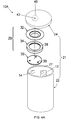
- FIG. 4A is a schematic view of a cylindrical battery of the invention.
- FIG. 4B shows a bottom view of the bottom part of the cylindrical battery of FIG. 4A .
- terminals of the batteries of the invention mean the parts or surfaces of the batteries to which external electric circuits are connected.
- the batteries of the invention typically include a first terminal in electrical communication with a first electrode, and a second terminal in electrical communication with a second electrode.
- the first and second electrodes are contained within the cell casing of a battery of the invention, for example, in a “jelly roll” form.
- the first terminal can be either a positive terminal in electrical communication with a positive electrode of the battery, or a negative terminal in electrical communication with a negative electrode of the battery, and vice versa for the second terminal.
- the first terminal is a negative terminal in electrical communication with a negative electrode of the battery
- the second terminal is a positive terminal in electrical communication with a positive electrode of the battery.
- the phrase “electrically connected” or “in electrical communication” means certain parts are in communication with each other by flow of electrons through conductors, as opposed to electrochemical communication which involves flow of ions, such as Li + , through electrolytes.
- FIG. 1 shows battery 10 of one embodiment of the invention.
- FIGS. 2A and 2B show a top view and cross-sectional view of battery 10 , respectively.
- battery 10 includes first electrode 12 and second electrode 14 .
- First electrode 12 is electrically connected to feed-through device 16 , which includes first component 18 , which is proximal to first electrode 12 , and second component 20 , which is distal to first electrode 12 .
- the electrodes 12 , 14 are placed inside battery can 21 that includes cell casing 22 and lid 24 , i.e., internal space 27 defined by cell casing 22 and lid 24 .
- Cell casing 22 and lid 24 of battery 10 are in electrical communication with each other.
- feed-through includes any material or device that connects electrode 12 of battery 10 , within internal space 27 defined by cell casing 22 and lid 24 , with a component of the battery external to that defined internal space.
- feed-through device 16 extends through a pass-through hole defined by lid 24 .
- Feed-through device 16 also can pass through lid 24 without deformation, such as bending, twisting and/or folding, and can increase cell capacity.
- One benefit of using such a feed-through device includes a potential increase (e.g., 5-15%) in cell capacity due to increased volume utilization, as compared to that of a conventional lithium battery in which current-carrying tabs are folded or bent into a cell casing and are welded with internal electrodes.
- Any other suitable means known in the art can be used in the invention to connect electrode 12 with a component of the battery external to battery can 21 , e.g., a terminal of the battery.
- Cell casing 22 and lid 24 can be made of any suitable conductive material which is essentially stable electrically and chemically at a given voltage of batteries, such as the lithium-ion batteries of the invention.
- suitable materials of cell casing 22 include aluminum, nickel, copper, steel, nickel-plated iron, stainless steel and combinations thereof.
- cell casing 22 is of, or includes, aluminum.
- suitable materials of lid 24 are the same as those listed for cell casing 22 .
- lid 24 is made of the same material as cell casing 22 .
- both cell casing 22 and lid 24 are formed of, or include, aluminum.
- Lid 24 can hermetically seal cell casing 22 by any suitable method known in the art.
- lid 24 and cell casing 22 are welded to each other.
- other forms of electrical connection of lid 24 to cell casing 22 known in the art, such as crimping can be employed in the invention.
- Battery can 21 for example, lid 24 , is electrically insulated from feed-through device 16 , for example, by an insulating gasket (not shown).
- the insulating gasket is formed of a suitable insulating material, such as polypropylene, polyvinylfluoride (PVF), etc.
- At least one of cell casing 22 and lid 24 of battery can 21 are in electrical communication with second electrode 14 of battery 10 through CID 28 .
- Battery can 21 i.e., cell casing 22 and lid 24 , is electrically insulated from a first terminal of battery 10 , and at least a portion of battery can 21 is at least a component of a second terminal of battery 10 , or is electrically connected to the second terminal.
- at least a portion of lid 24 or the bottom of cell casing 22 serves as a second terminal of battery 10
- feed-through device 16 includes top conductive layer 26 , which can serve as a first terminal of battery 10 in electrical communication with first electrode 12 .
- First component 18 , second component 20 and top conductive layer 26 each and independently can be made of any suitable conductive material known in the art, for example, nickel.
- Battery 10 of the invention includes CID 28 . Although one CID 28 is employed in battery 10 , more than one CID 28 can be employed in the invention.
- CID 28 includes first conductive plate 30 and second conductive plate 32 in electrical communication with each other (e.g., by welding, crimping, riveting, etc.). First conductive plate 30 is in electrical communication with second electrode 14 , and second conductive plate 32 is in electrical contact with battery can 21 , for example, lid 24 .
- second conductive plate 32 separates from (e.g., deforms away or is detached from) first conductive plate 30 when gauge pressure inside the battery is greater than a predetermined value, for example, between about 5 kg/cm 2 and about 10 kg/cm 2 , whereby a current flow between second electrode 14 and battery can 21 , at least a portion of which is at least a component of a second terminal, or is electrically connected to the second terminal, is interrupted.
- a predetermined value for example, between about 5 kg/cm 2 and about 10 kg/cm 2
- venting means 56 e.g, at cell wall or the bottom part of cell casing 22 , or second conductive plate 32 , which will be discussed later in detail, when the internal pressure kept increasing and reaches a predetermined value for activation of venting means 56 .
- the predetermined gauge pressure value for activation of venting means 56 is higher than that for activation of CID 28 , for example, between about 5 kg/cm 2 and about 10 kg/cm 2 .
- This feature helps prevent premature gas leakage, which can damage neighboring batteries (or cells) which are operating normally. So, when one of a plurality of cells in the battery packs of the invention is damaged, the other healthy cells are not damaged.
- gauge pressure values or sub-ranges suitable for the activation of CID 28 and those for activation of venting means 56 are selected from among the predetermined gauge pressure ranges such that there is no overlap between the selected pressure values or sub-ranges.
- the values or ranges of gauge pressure for the activation of CID 28 and those for the activation of venting means 56 differ by at least about 2 kg/cm 2 pressure difference, more preferably by at least about 4 kg/cm 2 , even more preferably by at least about 6 kg/cm 2 , such as by about 7 kg/cm 2 .
- CID 28 further includes insulator 34 (e.g., insulating layer or insulating gasket) between a portion of first conductive plate 30 and second conductive plate 32 .
- CID 28 is in electrical communication with cell casing 22 of the battery.
- the second conductive plate separates from (e.g., deforms away or is detached from) the first conductive plate when pressure inside the battery is greater than a predetermined value, for example, an internal gauge pressure in a range of between about 5 kg/cm 2 and about 10 kg/cm 2 , whereby a current flow between the second electrode and the second terminal is interrupted.
- At least one of first conductive plate 30 and insulator 34 of CID 28 includes at least one hole (e.g., holes 36 or 38 in FIG. 1 ) through which gas within battery 10 is in fluid communication with second conductive plate 32 .
- CID 28 further includes end plate 40 disposed over second conductive plate 32 , and defining at least one hole 42 through which second conductive plate 32 is in fluid communication with the atmosphere outside the battery.
- end plate 40 is a part of battery can 21 , as shown in FIG. 1 where end plate 40 is a part of lid 24 of battery can 21 .
- end plate 40 is at battery can 21 of battery 10 , for example, over, under or at lid 24 of battery can 21 , and in electrical communication with battery can 21 .
- CID 28 in the invention is placed within battery can 21 , or alternatively, a portion of CID 28 is within battery can 21 and another portion of CID 28 is at or above battery can 21 .
- CID 28 can be electrically connected to lid 24 by any suitable means, such as welding, crimping, etc.
- at least one component of CID 28 , first and second conductive plates, 30 , 32 , insulator 34 and end plate 40 are positioned within battery can 21 .
- At least one component of CID 28 e.g., first and second conductive plates, 30 , 32 , insulator 34 , and end plate 40 , is seated within a recess at battery can 21 , e.g., lid 24 .
- at least one of first and second conductive plates, 30 , 32 , and end plate 40 is a component of battery can 21 , e.g., lid 24 , or side or bottom of cell casing 22 .
- at least one of first and second conductive plates, 30 , 32 , and end plate 40 is a portion of battery can 21 , e.g., lid 24 , or side or bottom of cell casing 22 .
- first and second conductive plates, 30 , 32 , and end plate 40 is coined or stamped at lid 24 , or the side or the bottom of cell casing 22 , preferably at lid 24 .
- end plate 40 is a part of lid 24 (e.g., coined or stamped), and first and second conductive plates, 30 , 32 , are placed within cell casing 22 , as shown in FIG. 1 .
- First conductive plate 30 and second conductive plate 32 can be made of any suitable conductive material known in the art for a battery. Examples of suitable materials include aluminum, nickel and copper, preferably aluminum.
- battery can 21 e.g., cell casing 22 and lid 24
- first conductive plate 30 and second conductive plate 32 are made of substantially the same metals.
- substantially same metals means metals that have substantially the same chemical and electrochemical stability at a given voltage, e.g., the operation voltage of a battery. More preferably, battery can 21 , first conductive plate 30 and second conductive plate 32 are made of the same metal, such as aluminum.
- Cell casing 22 (e.g., the cell wall or the bottom part) includes at least one venting means 56 as a means for venting interior space 27 when necessary, such as when gauge pressure within lithium ion battery 10 is greater than a value of between about 10 kg/cm 2 and about 20 kg/cm 2 .
- second conductive plate 32 includes at least one venting means 56 (not shown). It is to be understood that any suitable type of venting means can be employed as long as the means provide hermetic sealing in normal battery operation conditions. Various suitable examples of venting means are described in U.S. Provisional Application No. 60/717,898, filed on Sep. 16, 2005, the entire teachings of which are incorporated herein by reference.
- venting means 56 include vent scores.
- the term “score” means partial incision of section(s) of a cell casing, such as cell casing 22 , that is designed to allow the cell pressure and any internal cell components to be released at a defined internal gauge pressure, (e.g., between about 10 and about 20 kg/cm 2 ).
- the vent score is directionally positioned away from a user/or neighboring cells. As shown, more than one vent score can be employed. In some embodiments, pattern vent scores can be employed. The vent score can be parallel, perpendicular, diagonal to a major stretching (or drawing) direction of the cell casing material during creation of the shape of cell casing 22 . Consideration is also given to vent score properties, such as depth, shape and length (size).
- the batteries of the invention can further include a positive thermal coefficient layer (PTC) in electrical communication with either the first terminal or the second terminal, preferably in electrical communication with the first terminal.
- PTC positive thermal coefficient layer
- Suitable PTC materials are those known in the art. Generally, suitable PTC materials are those that, when exposed to an electrical current in excess of a design threshold, its electrical conductivity decreases with increasing temperature by several orders of magnitude (e.g., 10 4 to 10 6 or more). Once the electrical current is reduced below a suitable threshold, in general, the PTC material substantially returns to the initial electrical resistivity.
- the PTC material includes small quantities of semiconductor material in a polycrystalline ceramic, or a slice of plastic or polymer with carbon grains embedded in it.
- the semiconductor material or the plastic or polymer with embedded carbon grains forms a barrier to the flow of electricity and causes electrical resistance to increase precipitously.
- the temperature at which electrical resistivity precipitously increases can be varied by adjusting the composition of the PTC material, as is known in the art.
- An “operating temperature” of the PTC material is a temperature at which the PTC exhibits an electrical resistivity about half way between its highest and lowest electrical resistance.
- the operating temperature of the PTC layer employed in the invention is between about 70° Celsius and about 150° Celsius.
- Examples of specific PTC materials include polycrystalline ceramics containing small quantities of barium titanate (BaTiO 3 ), and polyolefins including carbon grains embedded therein.
- Examples of commercially available PTC laminates that include a PTC layer sandwiched between two conducting metal layers include LTP and LR4 series manufactured by Raychem Co. Generally, the PTC layer has a thickness in a range of about 50 ⁇ m and about 300 ⁇ m.
- the PTC layer includes electrically conductive surface, the total area of which is at least about 25% or at least about 50% (e.g., about 48% or about 56%) of the total surface area of lid 24 or the bottom of battery 10 .
- the total surface area of the electrically conductive surface of the PTC layer can be at least about 56% of the total surface area of lid 24 or the bottom of battery 10 .
- Up to 100% of the total surface area of lid 24 of battery 10 can occupied by the electrically conductive surface of the PTC layer.
- the whole, or part, of the bottom of battery 10 can be occupied by the electrically conductive surface of the PTC layer.
- the PTC layer can be positioned internally or externally to the cell can (e.g., lid 24 or the bottom part of cell casing 22 ), preferably externally to the cell can, for example, over lid 24 of the cell can.
- the PTC layer is between a first conductive layer and a second conductive layer and at least a portion of the second conductive layer is at least a component of the first terminal, or is electrically connected to the first terminal.
- the first conductive layer is connected to the feed-through device. Suitable examples of such a PTC layer sandwiched between the first and second conductive layers are described in U.S. patent application Ser. No. 11/474,081, filed on Jun. 23, 2006, the entire teachings of which are incorporated herein by reference.
- the cells of batteries of the invention are rechargeable, such as rechargeable lithium-ion cells or batteries.
- the cells or batteries of the invention can be in any suitable shape, e.g., cylindrical or prismatic.
- the cells of batteries of the invention are cylindrical (e.g., 26650, 18650, or 14500 configuration), as shown in FIGS. 4A and 4B .
- FIG. 4B shows the bottom part of cell casing 22 of battery 10 A of FIG. 4A .
- conductive layer 26 at feed-through device 16 which is in electrical communication with first electrode 12 , is placed at the bottom part of cell casing 22 , as shown in FIG. 4B .
- Conductive layer 26 can serve as a first terminal of battery 10 A.
- at least one venting means 56 is placed at the bottom part of cell casing 22 (see FIG. 4B ).
- venting means 56 can be placed at second conductive plate 32 (not shown).
- the cells or batteries of the invention are prismatic, as shown in FIG. 1 (stacked or wound, e.g., 183665 or 103450 configuration).
- the cells or batteries of the invention are of a prismatic shape that is oblong.
- the present invention can use all types of prismatic cell casings, an oblong cell casing is preferred partly due to the two features described below.
- an oblong shape such as the 183665 form factor
- the available internal volume of an oblong shape is larger than the volume of two 18650 cells, when comparing stacks of the same external volume.
- the oblong cell When assembled into a battery pack, the oblong cell fully utilizes more of the space that is occupied by the battery pack.
- This enables novel design changes to the internal cell components that can increase key performance features without sacrificing cell capacity relative to that found in the industry today.
- Due to the larger available volume one can elect to use thinner electrodes, which have relatively higher cycle life and a higher rate capability.
- an oblong can has larger flexibility. For instance, an oblong shape can flex more at the waist point compared to a cylindrically shaped can, which allows less flexibility as stack pressure is increasing upon charging. The increased flexibility decreases mechanical fatigue on the electrodes, which, in turn, causes higher cycle life. Also, clogging of pores of a separator in batteries can be improved by the relatively lower stack pressure.
- the oblong shape provides a snug fit to the jelly roll, which minimizes the amount of electrolyte necessary for the battery.
- the relatively lower amount of electrolyte results in less available reactive material during a misuse scenario and hence higher safety.
- cost is lower due to a lower amount of electrolyte.
- a prismatic can with a stacked electrode structure, whose cross-section is in a rectangular shape full volume utilization is possible without unnecessary electrolyte, but this type of can design is more difficult and hence more costly from a manufacturing point-of-view.
- a plurality of lithium-ion batteries of the invention can be connected in a battery pack, wherein each of the batteries (cells) is connected with each other in series, parallel, or in series and parallel. In some battery packs of the invention, there are no parallel connections between the batteries.
- At least one cell has a prismatic shaped cell casing, and more preferably, an oblong shaped cell casing, as shown in FIG. 1 . More preferably, at least one cell has an 183665 configuration.
- the capacity of the cells in the battery pack is typically equal to or greater than about 3.0 Ah, more preferably equal to or greater than about 4.0 Ah.
- the internal impedance of the cells is preferably less than about 50 milliohms, and more preferably less than 30 milliohms.
- the lithium-ion batteries and battery packs of the invention can be used for portable power devices, such as portable computers, power tools, toys, portable phones, camcorders, PDAs and the like.
- portable electronic devices such as portable computers, power tools, toys, portable phones, camcorders, PDAs and the like.
- their charges are, in general, designed for a 4.20 V charging voltage.
- the lithium-ion batteries and battery packs of the invention are particularly useful for these portable electronic devices.
- the present invention also includes methods of producing a battery, such as a lithium-ion battery, as described above.
- the methods include forming a cell casing as described above, and disposing a first electrode and a second electrode within the cell casing.
- a current interrupt device, as described above e.g., current interrupt device 28 , is formed and electrically connected with the cell casing.
- Positive and negative electrodes and electrolytes for the lithium-ion batteries of the invention can be formed by suitable methods known in the art.
- suitable negative-active materials for the negative electrodes include any material allowing lithium to be doped or undoped in or from the material.
- suitable negative-active materials include carbonaceous materials, for example, non-graphitic carbon, artificial carbon, artificial graphite, natural graphite, pyrolytic carbons, cokes such as pitch coke, needle coke, petroleum coke, graphite, vitreous carbons, or a heat-treated organic polymer compounds obtained by carbonizing phenol resins, furan resins, or similar, carbon fibers, and activated carbon.
- metallic lithium, lithium alloys, and an alloy or compound thereof are usable as the negative active materials.
- the metal element or semiconductor element allowed to form an alloy or compound with lithium may be a group IV metal element or semiconductor element, such as but not limited to, silicon or tin.
- amorphous tin that is doped with a transition metal such as cobalt or iron/nickel, is a metal that is suitable as an anode material in these types of batteries.
- Oxides allowing lithium to be doped or undoped in or out from the oxide at a relatively basic potential, such as iron oxide, ruthenium oxide, molybdenum oxide, tungsten oxide, titanium oxide, and tin oxide, and nitrides, similarly, are usable as the negative-active materials.
- Suitable positive-active materials for the positive electrodes include any material known in the art, for example, lithium nickelate (e.g., Li 1+x NiM′O 2 ), lithium cobaltate (e.g., Li 1+x CoO 2 ), olivine-type compounds (e.g., Li 1+x FePO 4 ), manganate spinel (e.g., Li 1+x9 Mn 2 ⁇ y9 O 4 (x9 and y9 are each independently equal to or greater than zero and equal to or less than 0.3) or Li 1+x1 (Mn 1 ⁇ y1 A′ y2)2 ⁇ x2 O z1 ) (x1 and x2 are each independently equal to or greater than 0.01 and equal to or less than 0.3; y1 and y2 are each independently equal to or greater than 0.0 and equal to or less than 0.3; z1 is equal to or greater than 3.9 and equal to or less than 4.1), and mixtures thereof.
- lithium nickelate e.g., Li 1+x NiM′
- the positive-active materials for the positive electrodes of the invention include a lithium cobaltate, such as Li (1+x8) CoO z8 . More specifically, a mixture of about 60-90 wt % (e.g. about 80 wt %) of a lithium cobaltate, such as Li (1+x8) CoO z8 , and about 40-10 wt % (e.g., about 20 wt %) of a manganate spinel (e.g., having about 100-115 mAh/g), such as Li (1+x1) Mn 2 O z1 , preferably Li (1+x1) Mn 2 O 4 , is employed for the invention.
- a lithium cobaltate such as Li (1+x8) CoO z8
- the value x1 is equal to or greater than zero and equal to or less than 0.3 (e.g., 0.05 ⁇ x1 ⁇ 0.15).
- the value z1 is equal to or greater than 3.9 and equal to or greater than 4.2.
- the value x8 is equal to or greater than zero and equal to or less than 0.2.
- the value z8 is equal to or greater than 1.9 and equal to or greater than 2.1.
- the positive-active materials for the invention include a mixture that includes a lithium cobaltate, such as Li (1+x8) CoO z8 , and a manganate spinel represented by an empirical formula of Li (1+x1) (Mn 1 ⁇ y1 A′ y2 ) 2 ⁇ x2 O z1 .
- the values x1 and x2 are each independently equal to or greater than 0.01 and equal to or less than 0.3.
- the values y1 and y2 are each independently equal to or greater than 0.0 and equal to or less than 0.3.
- the value z1 is equal to or greater than 3.9 and equal to or less than 4.2.
- A′ is at least one member of the group consisting of magnesium, aluminum, cobalt, nickel and chromium. More specifically, the lithium cobaltate and the manganate spinel are in a weight ratio of lithium cobaltate:manganate spinel between about 0.95:0.05 and about 0.9:0.1 to about 0.6:0.4.
- the positive-active materials for the invention include a mixture that includes 100% of a lithium cobaltate, such as Li (1+x8) CoO z8 .
- the positive-active materials for the invention include at least one lithium oxide selected from the group consisting of: a) a lithium cobaltate; b) a lithium nickelate; c) a manganate spinel represented by an empirical formula of Li (1+x1) (Mn 1 ⁇ y1 A′ y2 ) 2 ⁇ x2 O z1 ; d) a manganate spinel represented by an empirical formula of Li (1+x1) Mn 2 O z1 or Li 1+x9 Mn 2 ⁇ y9 O 4 ; and e) an olivine compound represented by an empirical formula of Li (1 ⁇ x10) A′′ x10 MPO 4 .
- the values of x1, z1, x9 and y9 are as described above.
- the value, x2 is equal to or greater than 0.01 and equal to or less than 0.3.
- the values of y1 and y2 are each independently equal to or greater than 0.0 and equal to or less than 0.3.
- A′ is at least one member of the group consisting of magnesium, aluminum, cobalt, nickel and chromium.
- the value, x10 is equal to or greater than 0.05 and equal to or less than 0.2, or the value, x10, is equal to or greater than 0.0 and equal to or less than 0.1.
- M is at least one member of the group consisting of iron, manganese, cobalt and magnesium.
- A′′ is at least one member of the group consisting of sodium, magnesium, calcium, potassium, nickel and niobium.
- a lithium nickelate that can be used in the invention includes at least one modifier of either the Li atom or Ni atom, or both.
- a “modifier” means a substituent atom that occupies a site of the Li atom or Ni atom, or both, in a crystal structure of LiNiO 2 .
- the lithium nickelate includes only a modifier of, or substituent for, Li atoms (“Li modifier”).
- the lithium nickelate includes only a modifier of, or substituent for, Ni atoms (“Ni modifier”).
- the lithium nickelate includes both the Li and Ni modifiers. Examples of Li modifiers include barium (Ba), magnesium (Mg), calcium (Ca) and strontium (Sr).
- Ni modifiers include those modifiers for Li and, in addition, aluminum (Al), manganese (Mn) and boron (B).
- Other examples of Ni modifiers include cobalt (Co) and titanium (Ti).
- the lithium nickelate is coated with LiCoO 2 .
- the coating can be, for example, a gradient coating or a spot-wise coating.
- Li x3 Ni 1 ⁇ z3 M′ z3 O 2 where 0.05 ⁇ x3 ⁇ 1.2 and 0 ⁇ z3 ⁇ 0.5
- M′ is one or more elements selected from a group consisting of Co, Mn, Al, B, Ti, Mg, Ca and Sr.
- M′ is one or more elements selected from a group consisting of Mn, Al, B, Ti, Mg, Ca and Sr.
- Li x4 A* x5 Ni (1 ⁇ y4 ⁇ z4) Co y4 Q z4 O a x4 is equal to or greater than about 0.1 and equal to or less than about 1.3; x5 is equal to or greater than 0.0 and equal to or less than about 0.2; y4 is equal to or greater than 0.0 and equal to or less than about 0.2; z4 is equal to or greater than 0.0 and equal to or less than about 0.2; a is greater than about 1.5 and less than about 2.1; A* is at least one member of the group consisting of barium (Ba), magnesium (Mg) and calcium (Ca); and Q is at least one member of the group consisting of aluminum (Al), manganese (Mn) and boron (B).
- y4 is greater than zero.
- x5 is equal to zero, and z4 is greater than 0.0 and equal to or less than about 0.2.
- z4 is equal to zero, and x5 is greater than 0.0 and equal to or less than about 0.2.
- x5 and z4 are each independently greater than 0.0 and equal to or less than about 0.2.
- x5, y4 and z4 are each independently greater than 0.0 and equal to or less than about 0.2.
- Various examples of lithium nickelates where x5, y4 and z4 are each independently greater than 0.0 and equal to or less than about 0.2 can be found in U.S. Pat. Nos. 6,855,461 and 6,921,609 (the entire teachings of which are incorporated herein by reference).
- a specific example of the lithium nickelate is LiNi 0.8 CO 0.15 Al 0.05 O 2 .
- a preferred specific example is LiCoO 2 -coated LiNi 0.8 Co 0.15 Al 0.05 O 2 .
- LiCoO 2 doe not fully coat the nickelate core particle.
- the composition of LiNi 0.8 Co 0.15 Al 0.05 O 2 coated with LiCoO 2 can naturally deviate slightly in composition from the 0.8:0.15:0.05 weight ratio between Ni:Co:Al. The deviation can range about 10-15% for the Ni, 5-10% for Co and 2-4% for Al.
- Another specific example of the lithium nickelate is Li 0.97 Mg 0.03 Ni 0.9 Cu 0.1 O 2 .
- a preferred specific example is LiCoO 2 -coated Li 0.97 Mg 0.03 Ni 0.9 Cu 0.1 O 2 .
- the composition of Li 0.97 Mg 0.03 Ni 0.9 Cu 0.1 O 2 coated with LiCoO 2 can deviate slightly in composition from the 0.03:0.9:0.1 weight ratio between Mg:Ni:Co. The deviation can range about 2-4% for Mg, 10-15% for Ni and 5-10% for Co.
- Another preferred nickelate that can be used in the present invention is Li(Ni 1/3 Co 1/3 Mn 1/3 )O 2 , also called “333-type nickelate.” This 333-type nickelate optionally can be coated with LiCoO 2 , as described above.
- lithium cobaltates that can be used in the invention include Li 1+x8 CoO 2 that is modified by at least one of Li or Co atoms.
- Li modifiers are as described above for Li of lithium nickelates.
- Co modifiers include the modifiers for Li and aluminum (Al), manganese (Mn) and boron (B).
- Ni nickel
- Ti titanium
- lithium cobaltates represented by an empirical formula of Li x6 M′ (1 ⁇ y6) Co (1 ⁇ z6) M′′ z6 O 2 , where x6 is greater than 0.05 and less than 1.2; y6 is equal to or greater than 0 and less than 0.1, z6 is equal to or greater than 0 and less than 0.5; M′ is at least one member of magnesium (Mg) and sodium (Na) and M′′ is at least one member of the group consisting of manganese (Mn), aluminum (Al), boron (B), titanium (Ti), magnesium (Mg), calcium (Ca) and strontium (Sr), can be used in the invention.
- lithium cobaltate that can be used in the invention is unmodified Li 1+8 CoO 2 , such as LiCoO 2 .
- the lithium cobaltate e.g., LiCoO 2
- the lithium cobaltate doped with Mg and/or coated with a refractive oxide or phosphate, such as ZrO 2 or Al(PO 4 ).
- lithium oxide compounds employed have a spherical-like morphology, since it is believed that this improves packing and other production-related characteristics.
- a crystal structure of each of the lithium cobaltate and lithium nickelate is independently a R-3m type space group (rhombohedral, including distorted rhombohedral).
- a crystal structure of the lithium nickelate can be in a monoclinic space group (e.g., P2/m or C2/m).
- olivine compounds that are suitable for use in the invention are generally represented by a general formula Li 1 ⁇ x2 A′′ x2 MPO 4 , where x2 is equal to or greater than 0.05, or x2 is equal to or greater than 0.0 and equal to or greater than 0.1; M is one or more elements selected from a group consisting of Fe, Mn, Co, or Mg; and A′′ is selected from a group consisting of Na, Mg, Ca, K, Ni, Nb.
- M is Fe or Mn. More preferably, LiFePO 4 or LiMnPO 4 , or both are used in the invention.
- the olivine compounds are coated with a material having relatively high electrical conductivity, such as carbon.
- carbon-coated LiFePO 4 or carbon-coated LiMnPO 4 is employed in the invention.
- olivine compounds where M is Fe or Mn can be found in U.S. Pat. No. 5,910,382 (the entire teachings of which are incorporated herein by reference).
- the olivine compounds typically have a small change in crystal structure upon charging/discharging, which generally makes the olivine compounds superior in terms of cycle characteristics. Also, safety is generally high, even when a battery is exposed to a high temperature environment.
- Another advantage of olivine compounds e.g., LiFePO 4 and LiMnPO 4 ) is their relatively low cost.
- Manganate spinel compounds have a manganese base, such as LiMn 2 O 4 . While the manganate spinel compounds typically have relatively low specific capacity (e.g., in a range of about 110 to 115 mAh/g), they have relatively high power delivery when formulated into electrodes and typically are safe in terms of chemical reactivity at higher temperatures. Another advantage of the manganate spinel compounds is their relatively low cost.
- A′ is one or more of Mg, Al, Co, Ni and Cr; x1 and x2 are each independently equal to or greater than 0.01 and equal to or less than 0.3; y1 and y2 are each independently equal to or greater than 0.0 and equal to or less than 0.3; z1 is equal to or greater than 3.9 and equal to or less than 4.1.
- A′ includes a M 3+ ion, such as Al 3+ , Co 3+ , Ni 3+ and Cr 3+ , more preferably Al 3+ .
- the manganate spinel compounds of Li (1+x1) (Mn 1 ⁇ y1 A′ y2 ) 2 ⁇ x2 O z1 can have enhanced cyclability and power compared to those of LiMn 2 O 4 .
- Another type of manganate spinel compounds that can be used in the invention is represented by an empirical formula of Li (1+x1) Mn 2 O z1 , where x1 and z1 are each independently the same as described above.
- the manganate spinel for the invention includes a compound represented by an empirical formula of Li 1+x9 Mn 2 ⁇ y9 O z9 where x9 and y9 are each independently equal to or greater than 0.0 and equal to or less than 0.3 (e.g., 0.05 ⁇ x9, y9 ⁇ 0.15); and z9 is equal to or greater than 3.9 and equal to or less than 4.2.
- Specific examples of the manganate spinel that can be used in the invention include LiMn 1.9 Al 0.1 O 4 , Li 1+x1 Mn 2 O 4 , Li 1+x7 Mn 2 ⁇ y7 O 4 , and their variations with Al and Mg modifiers.
- cathode materials described herein are characterized by empirical formulas that exist upon manufacture of lithium-ion batteries in which they are incorporated. It is understood that their specific compositions thereafter are subject to variation pursuant to their electrochemical reactions that occur during use (e.g., charging and discharging).
- non-aqueous electrolytes examples include a non-aqueous electrolytic solution prepared by dissolving an electrolyte salt in a non-aqueous solvent, a solid electrolyte (inorganic electrolyte or polymer electrolyte containing an electrolyte salt), and a solid or gel-like electrolyte prepared by mixing or dissolving an electrolyte in a polymer compound or the like.
- the non-aqueous electrolytic solution is typically prepared by dissolving a salt in an organic solvent.
- the organic solvent can include any suitable type that has been generally used for batteries of this type. Examples of such organic solvents include propylene carbonate (PC), ethylene carbonate (EC), diethyl carbonate (DEC), dimethyl carbonate (DMC), 1,2-dimethoxyethane, 1,2-diethoxyethane, ⁇ -butyrolactone, tetrahydrofuran, 2-methyl tetrahydrofuran, 1,3-dioxolane, 4-methyl-1,3-dioxolane, diethyl ether, sulfolane, methylsulfolane, acetonitrile, propionitrile, anisole, acetate, butyrate, propionate and the like. It is preferred to use cyclic carbonates such as propylene carbonate, or chain carbonates such as dimethyl carbonate and diethyl carbonate. These organic solvents can be used singly or
- Additives or stabilizers may also be present in the electrolyte, such as VC (vinyl carbonate), VEC (vinyl ethylene carbonate), EA (ethylene acetate), TPP (triphenylphosphate), phosphazenes, biphenyl (BP), cyclohexylbenzene (CHB), 2,2-diphenylpropane (DP), lithium bis(oxalato)borate (LiBoB), ethylene sulfate (ES) and propylene sulfate.
- VC vinyl carbonate
- VEC vinyl ethylene carbonate
- EA ethylene acetate
- TPP triphenylphosphate
- DP cyclohexylbenzene
- DP 2,2-diphenylpropane
- LiBoB lithium bis(oxalato)borate
- ES ethylene sulfate
- propylene sulfate propylene sulfate
- the solid electrolyte can include an inorganic electrolyte, a polymer electrolyte and the like insofar as the material has lithium-ion conductivity.
- the inorganic electrolyte can include, for example, lithium nitride, lithium iodide and the like.
- the polymer electrolyte is composed of an electrolyte salt and a polymer compound in which the electrolyte salt is dissolved.
- the polymer compounds used for the polymer electrolyte include ether-based polymers such as polyethylene oxide and cross-linked polyethylene oxide, polymethacrylate ester-based polymers, acrylate-based polymers and the like. These polymers may be used singly, or in the form of a mixture or a copolymer of two kinds or more.
- a matrix of the gel electrolyte may be any polymer insofar as the polymer is gelated by absorbing the above-described non-aqueous electrolytic solution.
- the polymers used for the gel electrolyte include fluorocarbon polymers such as polyvinylidene fluoride (PVDF), polyvinylidene-co-hexafluoropropylene (PVDF-HFP) and the like.
- Examples of the polymers used for the gel electrolyte also include polyacrylonitrile and a copolymer of polyacrylonitrile.
- Examples of monomers (vinyl based monomers) used for copolymerization include vinyl acetate, methyl methacrylate, butyl methacylate, methyl acrylate, butyl acrylate, itaconic acid, hydrogenated methyl acrylate, hydrogenated ethyl acrylate, acrlyamide, vinyl chloride, vinylidene fluoride, and vinylidene chloride.
- polymers used for the gel electrolyte further include acrylonitrile-butadiene copolymer rubber, acrylonitrile-butadiene-styrene copolymer resin, acrylonitrile-chlorinated polyethylene-propylenediene-styrene copolymer resin, acrylonitrile-vinyl chloride copolymer resin, acrylonitrile-methacylate resin, and acrlylonitrile-acrylate copolymer resin.
- acrylonitrile-butadiene copolymer rubber acrylonitrile-butadiene-styrene copolymer resin
- acrylonitrile-chlorinated polyethylene-propylenediene-styrene copolymer resin acrylonitrile-vinyl chloride copolymer resin
- acrylonitrile-methacylate resin acrylonitrile-methacylate resin
- acrlylonitrile-acrylate copolymer resin
- polymers used for the gel electrolyte include ether based polymers such as polyethylene oxide, copolymer of polyethylene oxide, and cross-linked polyethylene oxide.
- monomers used for copolymerization include polypropylene oxide, methyl methacrylate, butyl methacylate, methyl acrylate, butyl acrylate.
- a fluorocarbon polymer is preferably used for the matrix of the gel electrolyte.
- the electrolyte salt used in the electrolyte may be any electrolyte salt suitable for batteries of this type.
- the electrolyte salts include LiClO 4 , LiAsF 6 , LiPF 6 , LiBF 4 , LiB(C 6 H 5 ) 4 , LiB(C 2 O 4 ) 2 , CH 3 SO 3 Li, CF 3 SO 3 Li, LiCl, LiBr and the like.
- a separator separates the positive electrode from the negative electrode of the batteries.
- the separator can include any film-like material having been generally used for forming separators of non-aqueous electrolyte secondary batteries of this type, for example, a microporous polymer film made from polypropylene, polyethylene, or a layered combination of the two.
- a microporous separator made of glass fiber or cellulose material can in certain cases also be used. Separator thickness is typically between 9 and 25 ⁇ m.
- a positive electrode can be produced by mixing the cathode powders at a specific ratio. 90 wt % of this blend is then mixed together with 5 wt % of acetylene black as a conductive agent, and 5 wt % of PVDF as a binder. The mix is dispersed in N-methyl-2-pyrrolidone (NMP) as a solvent, in order to prepare slurry. This slurry is then applied to both surfaces of an aluminum current collector foil, having a typical thickness of about 20 um, and dried at about 100-150° C. The dried electrode is then calendared by a roll press, to obtain a compressed positive electrode.
- NMP N-methyl-2-pyrrolidone
- a negative electrode can be prepared by mixing 93 Wt % of graphite as a negative active material, 3 wt % acetylene black, and 4 wt % of PVDF as a binder.
- the negative mix was also dispersed in N-methyl-2-pyrrolidone as a solvent, in order to prepare the slurry.
- the negative mix slurry was uniformly applied on both surfaces of a strip-like copper negative current collector foil, having a typical thickness of about 10 um.
- the dried electrode is then calendared by a roll press to obtain a dense negative electrode.
- the negative and positive electrodes and a separator formed of a polyethylene film with micro pores, of thickness 25 um, are generally laminated and spirally wound to produce a spiral type electrode element.
- one or more positive lead strips are attached to the positive current electrode, and then electrically connected to the positive terminal of the batteries of the invention.
- a negative lead made of, e.g., nickel metal, connects the negative electrode, and then attached to a feed-through device, such as feed-through device 16 .
- An electrolyte of for instance EC:DMC:DEC with 1M LiPF 6 is vacuum filled in the cell casing of a lithium-ion battery of the invention, where the cell casing has the spirally wound “jelly roll.”
Landscapes
- Chemical & Material Sciences (AREA)
- Chemical Kinetics & Catalysis (AREA)
- Electrochemistry (AREA)
- General Chemical & Material Sciences (AREA)
- Engineering & Computer Science (AREA)
- Manufacturing & Machinery (AREA)
- Inorganic Chemistry (AREA)
- Materials Engineering (AREA)
- Connection Of Batteries Or Terminals (AREA)
- Secondary Cells (AREA)
Priority Applications (1)
| Application Number | Priority Date | Filing Date | Title |
|---|---|---|---|
| US11/821,585 US8071233B2 (en) | 2006-06-27 | 2007-06-22 | Integrated current-interrupt device for lithium-ion cells |
Applications Claiming Priority (2)
| Application Number | Priority Date | Filing Date | Title |
|---|---|---|---|
| US81677506P | 2006-06-27 | 2006-06-27 | |
| US11/821,585 US8071233B2 (en) | 2006-06-27 | 2007-06-22 | Integrated current-interrupt device for lithium-ion cells |
Publications (2)
| Publication Number | Publication Date |
|---|---|
| US20080008928A1 US20080008928A1 (en) | 2008-01-10 |
| US8071233B2 true US8071233B2 (en) | 2011-12-06 |
Family
ID=38779626
Family Applications (1)
| Application Number | Title | Priority Date | Filing Date |
|---|---|---|---|
| US11/821,585 Expired - Fee Related US8071233B2 (en) | 2006-06-27 | 2007-06-22 | Integrated current-interrupt device for lithium-ion cells |
Country Status (9)
| Country | Link |
|---|---|
| US (1) | US8071233B2 (enExample) |
| EP (1) | EP2038944B1 (enExample) |
| JP (1) | JP2009543293A (enExample) |
| KR (1) | KR101295037B1 (enExample) |
| CN (1) | CN101479865A (enExample) |
| AT (1) | ATE535951T1 (enExample) |
| ES (1) | ES2378263T3 (enExample) |
| TW (1) | TW200810200A (enExample) |
| WO (1) | WO2008002487A2 (enExample) |
Cited By (7)
| Publication number | Priority date | Publication date | Assignee | Title |
|---|---|---|---|---|
| US20100178539A1 (en) * | 2008-12-19 | 2010-07-15 | Boston-Power, Inc. | Modular CID Assembly for a Lithium Ion Battery |
| US20120048587A1 (en) * | 2010-08-30 | 2012-03-01 | Makita Corporation | Battery pack of electric power tool |
| WO2013188034A1 (en) | 2012-06-15 | 2013-12-19 | Boston-Power, Inc. | Secondary lithium ion battery with mixed nickelate cathodes |
| US8679670B2 (en) | 2007-06-22 | 2014-03-25 | Boston-Power, Inc. | CID retention device for Li-ion cell |
| US10707526B2 (en) | 2015-03-27 | 2020-07-07 | New Dominion Enterprises Inc. | All-inorganic solvents for electrolytes |
| US10707531B1 (en) | 2016-09-27 | 2020-07-07 | New Dominion Enterprises Inc. | All-inorganic solvents for electrolytes |
| US11444314B2 (en) * | 2019-07-10 | 2022-09-13 | National Engineering Research Center of Advanced Energy Storage Materials (Shenzhen) Co., Ltd | High-energy-density secondary lithium-ion battery |
Families Citing this family (37)
| Publication number | Priority date | Publication date | Assignee | Title |
|---|---|---|---|---|
| EP1907871A1 (en) | 2005-07-14 | 2008-04-09 | Boston-Power, Inc. | Control electronics for li-ion batteries |
| KR100662752B1 (ko) | 2005-10-04 | 2007-01-02 | 엘에스산전 주식회사 | 다극 배선용 차단기 |
| US7990102B2 (en) * | 2006-02-09 | 2011-08-02 | Karl Frederick Scheucher | Cordless power supply |
| US8026698B2 (en) | 2006-02-09 | 2011-09-27 | Scheucher Karl F | Scalable intelligent power supply system and method |
| US8131145B2 (en) * | 2006-02-09 | 2012-03-06 | Karl Frederick Scheucher | Lightweight cordless security camera |
| CN101479865A (zh) | 2006-06-27 | 2009-07-08 | 波士顿电力公司 | 用于锂离子电池的整合性电流中断装置 |
| TWI426678B (zh) | 2006-06-28 | 2014-02-11 | Boston Power Inc | 具有多重充電率之電子裝置、電池組、充電於電子裝置中的鋰離子電荷儲存電源供應器之方法及可攜式電腦 |
| USD632649S1 (en) | 2006-09-29 | 2011-02-15 | Karl F. Scheucher | Cordless power supply |
| US8084154B2 (en) * | 2007-02-08 | 2011-12-27 | Karl Frederick Scheucher | Battery pack safety and thermal management apparatus and method |
| US20090291330A1 (en) * | 2008-04-24 | 2009-11-26 | Boston-Power, Inc. | Battery with enhanced safety |
| FR2933240B1 (fr) * | 2008-06-25 | 2010-10-22 | Commissariat Energie Atomique | Electrolyte non-aqueux pour accumulateur au lithium a tension elevee |
| WO2010080588A1 (en) * | 2008-12-19 | 2010-07-15 | Boston-Power, Inc. | Modular cid assembly for a lithium ion battery |
| TWI499150B (zh) * | 2009-01-30 | 2015-09-01 | Boston Power Inc | 模組式電流中斷裝置、電池、及其製造方法 |
| US9711868B2 (en) * | 2009-01-30 | 2017-07-18 | Karl Frederick Scheucher | In-building-communication apparatus and method |
| US8472881B2 (en) | 2009-03-31 | 2013-06-25 | Karl Frederick Scheucher | Communication system apparatus and method |
| KR101056426B1 (ko) * | 2009-06-23 | 2011-08-11 | 에스비리모티브 주식회사 | 이차전지 및 그 모듈 |
| JP2013504145A (ja) | 2009-09-01 | 2013-02-04 | ボストン−パワー,インコーポレイテッド | 大規模蓄電池システムおよび組み立て方法 |
| JP5707499B2 (ja) * | 2010-10-20 | 2015-04-30 | カウンスィル オブ サイエンティフィック アンド インダストリアル リサーチCouncil Of Scientific & Industrial Research | 正極材料及び該正極材料からのリチウムイオン電池 |
| JP6382104B2 (ja) | 2011-07-24 | 2018-08-29 | 株式会社マキタ | 動力工具システム |
| EP2735075B1 (en) | 2011-07-24 | 2016-06-01 | Makita Corporation | Charger for hand-held power tool, power tool system and method of charging a power tool battery |
| EP3954505B1 (en) | 2011-07-24 | 2024-10-02 | Makita Corporation | Adapter for power tools |
| JP5822089B2 (ja) | 2011-10-06 | 2015-11-24 | トヨタ自動車株式会社 | 密閉型リチウム二次電池 |
| JP2013094877A (ja) * | 2011-10-31 | 2013-05-20 | Hitachi Koki Co Ltd | 電動工具 |
| KR20130085256A (ko) * | 2012-01-19 | 2013-07-29 | 삼성에스디아이 주식회사 | 리튬 이차 전지 |
| EP2869389B1 (en) * | 2012-06-29 | 2019-11-13 | Mitsubishi Chemical Corporation | Nonaqueous electrolytic solution and nonaqueous electrolytic solution cell using same |
| KR101754611B1 (ko) * | 2012-11-05 | 2017-07-06 | 삼성에스디아이 주식회사 | 리튬 이차 전지용 양극 조성물 및 이를 이용한 리튬 이차 전지 |
| JP5725381B2 (ja) * | 2013-01-23 | 2015-05-27 | トヨタ自動車株式会社 | 非水電解液二次電池及びその製造方法 |
| JP5963010B2 (ja) * | 2014-01-08 | 2016-08-03 | トヨタ自動車株式会社 | 非水電解液二次電池 |
| US10128486B2 (en) | 2015-03-13 | 2018-11-13 | Purdue Research Foundation | Current interrupt devices, methods thereof, and battery assemblies manufactured therewith |
| US10439196B2 (en) * | 2015-12-18 | 2019-10-08 | Bourns, Inc. | Electromechanical circuit breaker |
| CN108232098B (zh) * | 2016-12-09 | 2021-04-27 | 宁德时代新能源科技股份有限公司 | 二次电池 |
| CN108666461B (zh) | 2017-03-31 | 2020-11-20 | 比亚迪股份有限公司 | 电池盖板组件、单体电池、电池模组、动力电池包和电动汽车 |
| EP3385997A1 (en) * | 2017-04-04 | 2018-10-10 | Lithium Energy and Power GmbH & Co. KG | Secondary cell for a traction battery and method for manufacturing a secondary cell |
| US10461291B2 (en) | 2017-12-12 | 2019-10-29 | Ford Global Technologies, Llc | Current-interrupt device for battery cell |
| CN110061178B (zh) | 2018-01-18 | 2024-10-15 | 比亚迪股份有限公司 | 电池、电池组以及汽车 |
| JP7219290B2 (ja) | 2018-06-22 | 2023-02-07 | ボーンズ、インコーポレイテッド | 回路遮断器 |
| JP7778067B2 (ja) | 2019-08-27 | 2025-12-01 | ボーンズ、インコーポレイテッド | 電池パック用一体型熱遮断装置付きコネクタ |
Citations (91)
| Publication number | Priority date | Publication date | Assignee | Title |
|---|---|---|---|---|
| US4025696A (en) | 1976-05-24 | 1977-05-24 | Union Carbide Corporation | Safety switch for small diameter galvanic cells |
| US4028478A (en) | 1976-05-24 | 1977-06-07 | Union Carbide Corporation | Safety switch for sealed galvanic cells |
| US4576303A (en) | 1985-02-21 | 1986-03-18 | Bs&B Safety Systems, Inc. | Rupturable pressure relieving fluid containers |
| US4788112A (en) | 1987-08-17 | 1988-11-29 | Kung Chin Chung | Rechargeable storage battery |
| US4787180A (en) | 1988-01-29 | 1988-11-29 | Bs&B Safety Systems, Inc. | Vibration resistant rupturable pressure relief member |
| US4838447A (en) | 1987-06-29 | 1989-06-13 | Bs&B Safety Systems, Inc. | Pressure relief device with conical reverse buckling disc |
| US4943497A (en) | 1988-10-21 | 1990-07-24 | Sony Corporation | Cell having current cutoff valve |
| US4951697A (en) | 1989-11-27 | 1990-08-28 | Bs&B Safety Systems, Inc. | Rupture disk failure indicating apparatus |
| US4978947A (en) | 1989-05-25 | 1990-12-18 | Bs&B Safety Systems, Inc. | Rupturable fluid flow indicator |
| US5036632A (en) | 1990-05-14 | 1991-08-06 | Bs&B Safety Systems, Inc. | Pressure relief panel assembly |
| US5082133A (en) | 1991-08-01 | 1992-01-21 | Bs&B Safety Systems, Inc. | Low pressure rupture disk and assembly |
| CA2099657A1 (en) | 1992-08-10 | 1994-02-11 | Alexander H. Rivers-Bowerman | Electrochemical Cell and Method of Manufacturing Same |
| US5418082A (en) | 1992-06-12 | 1995-05-23 | Sony Corporation | Sealed battery with current cut off means |
| US5570803A (en) | 1992-01-21 | 1996-11-05 | Bs&B Safety Systems, Inc. | Rupturable pressure relieving apparatus and methods of manufacturing the same |
| US5585207A (en) | 1994-03-03 | 1996-12-17 | Japan Storage Battery Co., Ltd. | Battery and safety device therefor |
| CA2163187A1 (en) | 1995-11-17 | 1997-05-18 | Huanyu Mao | Aromatic monomer gassing agents for protecting non-aqueous lithium batteries against overcharge |
| US5691073A (en) | 1996-04-10 | 1997-11-25 | Duracell Inc. | Current interrupter for electrochemical cells |
| US5705290A (en) | 1995-08-11 | 1998-01-06 | Alps Electric Co., Ltd. | Secondary cell safety device including pressure release mechanism and current cutoff mechanism |
| US5707756A (en) | 1994-11-29 | 1998-01-13 | Fuji Photo Film Co., Ltd. | Non-aqueous secondary battery |
| US5738952A (en) | 1995-05-12 | 1998-04-14 | Sony Corporation | Enclosed-type secondary cell |
| US5741606A (en) | 1995-07-31 | 1998-04-21 | Polystor Corporation | Overcharge protection battery vent |
| US5750277A (en) | 1996-04-10 | 1998-05-12 | Texas Instruments Incorporated | Current interrupter for electrochemical cells |
| JPH10172528A (ja) | 1996-12-05 | 1998-06-26 | Sony Corp | 非水電解液電池 |
| EP0863559A1 (fr) | 1997-02-18 | 1998-09-09 | Koninklijke Philips Electronics N.V. | "Dispositif du type accumulateur plat comprenant une cellule electrochimique et des moyens de contact electrique" |
| US5821008A (en) | 1996-02-16 | 1998-10-13 | Fdk Corporation | Battery provided with explosion-proof components |
| WO1998045888A1 (en) | 1997-04-10 | 1998-10-15 | Duracell Inc. | Current interrupter for electrochemical cells |
| US5853912A (en) | 1996-07-10 | 1998-12-29 | Saft America, Inc. | Lithium ion electrochemical cell with safety valve electrical disconnect |
| JPH113698A (ja) | 1997-06-11 | 1999-01-06 | Japan Storage Battery Co Ltd | リチウムイオン二次電池 |
| US5869208A (en) | 1996-03-08 | 1999-02-09 | Fuji Photo Film Co., Ltd. | Lithium ion secondary battery |
| US5879832A (en) | 1996-10-02 | 1999-03-09 | Duracell Inc. | Current interrupter for electrochemical cells |
| US5879834A (en) | 1995-08-23 | 1999-03-09 | Nec Moli Energy (Canada) Ltd. | Polymerizable aromatic additives for overcharge protection in non-aqueous rechargeable lithium batteries |
| EP0930662A2 (en) | 1998-01-15 | 1999-07-21 | Texas Instruments Incorporated | Current interrupt apparatus for electrochemical cells |
| US5958617A (en) | 1996-12-11 | 1999-09-28 | Matsushita Electric Industrial Co., Ltd. | Thin type battery |
| US5962167A (en) | 1996-09-24 | 1999-10-05 | Shin-Kobe Electric Machinery Co., Ltd. | Non-aqueous liquid electrolyte secondary cell |
| EP0959508A1 (en) | 1998-05-22 | 1999-11-24 | Texas Instruments Incorporated | Current interrupt apparatus particularly adapted for use with prismatic electrochemical cells |
| EP0969535A1 (en) | 1997-02-17 | 2000-01-05 | Ngk Insulators, Ltd. | Lithium secondary battery |
| US6063518A (en) | 1996-11-28 | 2000-05-16 | Saft | Sealed electrochemical cell equipped with a circuit-breaking terminal |
| US6065485A (en) | 1997-04-14 | 2000-05-23 | Bs&B Safety Systems, Inc. | Two-way pressure relief assembly and method |
| US6087036A (en) | 1997-07-25 | 2000-07-11 | 3M Innovative Properties Company | Thermal management system and method for a solid-state energy storing device |
| US6114942A (en) | 1995-08-07 | 2000-09-05 | Kk Raychem | PTC device and battery pack using the same |
| US6165637A (en) | 1998-10-01 | 2000-12-26 | Alps Electric Co., Ltd. | Current path cut-off mechanism |
| US6228523B1 (en) | 1998-04-23 | 2001-05-08 | Alps Electric Co., Ltd. | Current path cut-off component of cell |
| US6274264B1 (en) | 1998-08-31 | 2001-08-14 | Alps Electric Co., Ltd. | Cell current cutoff mechanism |
| US6296970B1 (en) | 2000-01-21 | 2001-10-02 | Moltech Power Systems, Inc. | Connector assembly for connecting battery cells |
| US6296965B1 (en) | 1998-09-10 | 2001-10-02 | Alps Electric Co., Ltd. | Cell electrical path breaking mechanism |
| US20020004169A1 (en) | 2000-04-25 | 2002-01-10 | Atsuo Yamada | Positive electrode and non-aqueous electrolyte cell |
| JP2002025526A (ja) | 2000-07-07 | 2002-01-25 | Sony Corp | 非水電解液電池 |
| US6346344B1 (en) | 1998-07-28 | 2002-02-12 | Samsung Sdi Co., Ltd. | Circuit breaker for secondary battery |
| US6376120B1 (en) | 1998-06-15 | 2002-04-23 | Alps Electric Co., Ltd. | Current cutoff mechanism for cell |
| US20020051905A1 (en) * | 1997-10-14 | 2002-05-02 | Ngk Insulators, Ltd. | Lithium secondary battery |
| US6399237B1 (en) | 1999-07-08 | 2002-06-04 | Alcatel | Sealed storage cell with an aluminum terminal |
| US6403250B1 (en) | 1999-03-01 | 2002-06-11 | Alps Electric Co., Ltd. | Pressure sensitive current breaker for a cell |
| CN1372341A (zh) | 2001-02-23 | 2002-10-02 | 三洋电机株式会社 | 锂二次电池 |
| CN1435908A (zh) | 2002-01-31 | 2003-08-13 | 三洋电机株式会社 | 非水电解质电池 |
| US20030180615A1 (en) | 2002-01-29 | 2003-09-25 | The University Of Chicago | Protective coating on positive lithium-metal-oxide electrodes for lithium batteries |
| US6632572B1 (en) | 1999-06-30 | 2003-10-14 | Sanyo Electric Co., Ltd. | Lithium secondary battery |
| US6730430B2 (en) | 2001-07-09 | 2004-05-04 | Nan Ya Plastics Corporation | Explosion-proof safety structure for column shape lithium battery |
| EP1429402A2 (en) | 2000-10-20 | 2004-06-16 | Rayovac Corporation | Method and apparatus for regulating charging of electrochemical cells |
| US20040115523A1 (en) | 2001-02-14 | 2004-06-17 | Hayato Hommura | Non-aqueous electrolyte battery |
| US6805991B2 (en) | 2000-01-14 | 2004-10-19 | Sony Corporation | Nonaqueous electrolyte solution secondary battery |
| US20040228061A1 (en) | 2002-12-26 | 2004-11-18 | Samsung Sdi Co., Ltd | Protector and lithium secondary battery having the same |
| US20040232888A1 (en) | 2003-05-21 | 2004-11-25 | Burrus Philip H. | Current interrupt device for rechargeable cells |
| US20040234842A1 (en) | 2003-03-07 | 2004-11-25 | Katsuya Kawano | Hermetically sealed battery |
| EP1482577A1 (en) | 2002-02-13 | 2004-12-01 | Matsushita Electric Industrial Co., Ltd. | Method of manufacturing battery pack |
| US6878481B2 (en) | 2000-10-20 | 2005-04-12 | Rayovac Corporation | Method and apparatus for regulating charging of electrochemical cells |
| US20050214634A1 (en) | 2004-03-29 | 2005-09-29 | Kim Tae-Yong | Cap assembly and secondary battery with same |
| US20050233217A1 (en) | 2002-11-01 | 2005-10-20 | Toyoki Fujihara | Nonaqueous electrolyte secondary battery |
| US20060019150A1 (en) | 2004-07-23 | 2006-01-26 | Saft | Safety device for a sealed cell |
| US20060051666A1 (en) | 2004-07-29 | 2006-03-09 | Gil-Ho Kim | Secondary battery |
| US20060083984A1 (en) * | 2004-10-18 | 2006-04-20 | Oh Jeong W | Battery sheath having radiation layer formed thereon and lithium polymer battery using the same |
| US20060115713A1 (en) | 2004-10-28 | 2006-06-01 | Kim Jong K | Rechargeable battery |
| US20060121336A1 (en) | 2004-11-15 | 2006-06-08 | Yoon Jang H | Lithium rechargeable battery |
| WO2006071972A2 (en) | 2004-12-28 | 2006-07-06 | Boston-Power, Inc. | Lithium-ion secondary battery |
| US20060216588A1 (en) * | 2005-03-09 | 2006-09-28 | Kim Dae K | Cylindrical type secondary battery |
| US20060257745A1 (en) | 2005-02-15 | 2006-11-16 | Young-Min Choi | Cathode active material, method of preparing the same, and cathode and lithium battery containing the material |
| US20060275657A1 (en) | 2005-05-16 | 2006-12-07 | Kiyomi Kozuki | Sealed rechargeable battery and manufacturing method of the same |
| US20070026315A1 (en) | 2004-12-28 | 2007-02-01 | Lampe-Onnerud Christina M | Lithium-ion secondary battery |
| US7175935B2 (en) | 2001-10-12 | 2007-02-13 | John Welsh | Lithium manganese dioxide cell |
| WO2007072759A1 (ja) | 2005-12-20 | 2007-06-28 | Matsushita Electric Industrial Co., Ltd. | 非水電解質二次電池 |
| US20070298314A1 (en) | 2006-06-23 | 2007-12-27 | Partin Phillip E | Lithium battery with external positive thermal coefficient layer |
| WO2007149102A1 (en) | 2006-06-23 | 2007-12-27 | Boston-Power, Inc. | Lithium battery with external positive thermal coefficient layer |
| WO2008002487A2 (en) | 2006-06-27 | 2008-01-03 | Boston-Power, Inc. | Integrated current-interrupt device for lithium-ion cells |
| WO2008069476A1 (en) | 2006-12-05 | 2008-06-12 | Moon, Seung-Ja | Cylindrical secondary battery and method of manufacturing the same |
| WO2008140702A2 (en) | 2007-05-08 | 2008-11-20 | Bs & B Safety Systems Limited | Pressure response membrane |
| WO2009002438A1 (en) | 2007-06-22 | 2008-12-31 | Boston-Power, Inc. | Cid retention device for li-ion cell |
| US20090117451A1 (en) | 2007-11-01 | 2009-05-07 | Samsung Sdi Co., Ltd. | Cap assembly and secondary battery using the same |
| WO2009131894A1 (en) | 2008-04-24 | 2009-10-29 | Boston-Power, Inc. | Battery with enhanced safety |
| WO2010080588A1 (en) | 2008-12-19 | 2010-07-15 | Boston-Power, Inc. | Modular cid assembly for a lithium ion battery |
| US7763375B2 (en) | 2006-05-24 | 2010-07-27 | Eveready Battery Company, Inc. | Current interrupt device for batteries |
| US7763386B2 (en) | 2002-01-08 | 2010-07-27 | Sony Corporation | Cathode active material and non-aqueous electrolyte secondary cell using same |
| WO2010088332A1 (en) | 2009-01-30 | 2010-08-05 | Boston-Power, Inc. | Modular cid assembly for a lithium ion battery |
Family Cites Families (7)
| Publication number | Priority date | Publication date | Assignee | Title |
|---|---|---|---|---|
| JPH08171898A (ja) * | 1994-12-16 | 1996-07-02 | Fuji Elelctrochem Co Ltd | 防爆安全装置を備えた角形電気化学素子とその製造方法 |
| US5720277A (en) * | 1995-02-27 | 1998-02-24 | Siemens Elema Ab | Ventilator/Anaesthetic system with juxtaposed CO2 meter and expired gas flow meter |
| JP3254995B2 (ja) * | 1995-12-19 | 2002-02-12 | 松下電器産業株式会社 | 薄型電池用防爆封口板 |
| JPH11329405A (ja) * | 1998-05-21 | 1999-11-30 | At Battery:Kk | 非水電解液二次電池 |
| JP2000113912A (ja) * | 1998-10-01 | 2000-04-21 | Alps Electric Co Ltd | 電池の電路遮断機構 |
| AU3676900A (en) * | 1999-04-12 | 2000-11-14 | Toyo Kohan Co. Ltd. | Safety device for enclosed cell and enclosed cell comprising the same |
| JP2004022477A (ja) * | 2002-06-20 | 2004-01-22 | Matsushita Electric Ind Co Ltd | 電池 |
-
2007
- 2007-06-22 CN CNA2007800241449A patent/CN101479865A/zh active Pending
- 2007-06-22 JP JP2009518176A patent/JP2009543293A/ja active Pending
- 2007-06-22 US US11/821,585 patent/US8071233B2/en not_active Expired - Fee Related
- 2007-06-22 AT AT07835857T patent/ATE535951T1/de active
- 2007-06-22 EP EP07835857A patent/EP2038944B1/en not_active Not-in-force
- 2007-06-22 KR KR1020097001798A patent/KR101295037B1/ko not_active Expired - Fee Related
- 2007-06-22 WO PCT/US2007/014592 patent/WO2008002487A2/en not_active Ceased
- 2007-06-22 TW TW096122455A patent/TW200810200A/zh unknown
- 2007-06-22 ES ES07835857T patent/ES2378263T3/es active Active
Patent Citations (105)
| Publication number | Priority date | Publication date | Assignee | Title |
|---|---|---|---|---|
| US4025696A (en) | 1976-05-24 | 1977-05-24 | Union Carbide Corporation | Safety switch for small diameter galvanic cells |
| US4028478A (en) | 1976-05-24 | 1977-06-07 | Union Carbide Corporation | Safety switch for sealed galvanic cells |
| US4576303A (en) | 1985-02-21 | 1986-03-18 | Bs&B Safety Systems, Inc. | Rupturable pressure relieving fluid containers |
| US4838447A (en) | 1987-06-29 | 1989-06-13 | Bs&B Safety Systems, Inc. | Pressure relief device with conical reverse buckling disc |
| US4788112A (en) | 1987-08-17 | 1988-11-29 | Kung Chin Chung | Rechargeable storage battery |
| US4787180A (en) | 1988-01-29 | 1988-11-29 | Bs&B Safety Systems, Inc. | Vibration resistant rupturable pressure relief member |
| US4943497A (en) | 1988-10-21 | 1990-07-24 | Sony Corporation | Cell having current cutoff valve |
| US4978947A (en) | 1989-05-25 | 1990-12-18 | Bs&B Safety Systems, Inc. | Rupturable fluid flow indicator |
| US4951697A (en) | 1989-11-27 | 1990-08-28 | Bs&B Safety Systems, Inc. | Rupture disk failure indicating apparatus |
| US5036632A (en) | 1990-05-14 | 1991-08-06 | Bs&B Safety Systems, Inc. | Pressure relief panel assembly |
| US5082133A (en) | 1991-08-01 | 1992-01-21 | Bs&B Safety Systems, Inc. | Low pressure rupture disk and assembly |
| US5570803A (en) | 1992-01-21 | 1996-11-05 | Bs&B Safety Systems, Inc. | Rupturable pressure relieving apparatus and methods of manufacturing the same |
| US5678307A (en) | 1992-01-21 | 1997-10-21 | Bs&B Safety Systems, Inc. | Method of manufacturing rupturable pressure relieving apparatus |
| US5418082A (en) | 1992-06-12 | 1995-05-23 | Sony Corporation | Sealed battery with current cut off means |
| CA2099657A1 (en) | 1992-08-10 | 1994-02-11 | Alexander H. Rivers-Bowerman | Electrochemical Cell and Method of Manufacturing Same |
| US5585207A (en) | 1994-03-03 | 1996-12-17 | Japan Storage Battery Co., Ltd. | Battery and safety device therefor |
| US5707756A (en) | 1994-11-29 | 1998-01-13 | Fuji Photo Film Co., Ltd. | Non-aqueous secondary battery |
| US5738952A (en) | 1995-05-12 | 1998-04-14 | Sony Corporation | Enclosed-type secondary cell |
| US5741606A (en) | 1995-07-31 | 1998-04-21 | Polystor Corporation | Overcharge protection battery vent |
| US6114942A (en) | 1995-08-07 | 2000-09-05 | Kk Raychem | PTC device and battery pack using the same |
| US5705290A (en) | 1995-08-11 | 1998-01-06 | Alps Electric Co., Ltd. | Secondary cell safety device including pressure release mechanism and current cutoff mechanism |
| US5879834A (en) | 1995-08-23 | 1999-03-09 | Nec Moli Energy (Canada) Ltd. | Polymerizable aromatic additives for overcharge protection in non-aqueous rechargeable lithium batteries |
| CA2163187A1 (en) | 1995-11-17 | 1997-05-18 | Huanyu Mao | Aromatic monomer gassing agents for protecting non-aqueous lithium batteries against overcharge |
| US6033797A (en) | 1995-11-17 | 2000-03-07 | Nec Moli Energy Limited | Aromatic monomer gassing agents for protecting non-aqueous lithium batteries against overcharge |
| US5776627A (en) | 1995-11-17 | 1998-07-07 | Moli Energy (1990) Limited | Aromatic monomer gassing agents for protecting non-aqueous lithium batteries against overcharge |
| US5821008A (en) | 1996-02-16 | 1998-10-13 | Fdk Corporation | Battery provided with explosion-proof components |
| US5869208A (en) | 1996-03-08 | 1999-02-09 | Fuji Photo Film Co., Ltd. | Lithium ion secondary battery |
| US5750277A (en) | 1996-04-10 | 1998-05-12 | Texas Instruments Incorporated | Current interrupter for electrochemical cells |
| US5691073A (en) | 1996-04-10 | 1997-11-25 | Duracell Inc. | Current interrupter for electrochemical cells |
| US5853912A (en) | 1996-07-10 | 1998-12-29 | Saft America, Inc. | Lithium ion electrochemical cell with safety valve electrical disconnect |
| US5962167A (en) | 1996-09-24 | 1999-10-05 | Shin-Kobe Electric Machinery Co., Ltd. | Non-aqueous liquid electrolyte secondary cell |
| US5879832A (en) | 1996-10-02 | 1999-03-09 | Duracell Inc. | Current interrupter for electrochemical cells |
| US6063518A (en) | 1996-11-28 | 2000-05-16 | Saft | Sealed electrochemical cell equipped with a circuit-breaking terminal |
| JPH10172528A (ja) | 1996-12-05 | 1998-06-26 | Sony Corp | 非水電解液電池 |
| US5958617A (en) | 1996-12-11 | 1999-09-28 | Matsushita Electric Industrial Co., Ltd. | Thin type battery |
| EP0969535A1 (en) | 1997-02-17 | 2000-01-05 | Ngk Insulators, Ltd. | Lithium secondary battery |
| EP0863559A1 (fr) | 1997-02-18 | 1998-09-09 | Koninklijke Philips Electronics N.V. | "Dispositif du type accumulateur plat comprenant une cellule electrochimique et des moyens de contact electrique" |
| WO1998045888A1 (en) | 1997-04-10 | 1998-10-15 | Duracell Inc. | Current interrupter for electrochemical cells |
| US6065485A (en) | 1997-04-14 | 2000-05-23 | Bs&B Safety Systems, Inc. | Two-way pressure relief assembly and method |
| JPH113698A (ja) | 1997-06-11 | 1999-01-06 | Japan Storage Battery Co Ltd | リチウムイオン二次電池 |
| US6087036A (en) | 1997-07-25 | 2000-07-11 | 3M Innovative Properties Company | Thermal management system and method for a solid-state energy storing device |
| US20020051905A1 (en) * | 1997-10-14 | 2002-05-02 | Ngk Insulators, Ltd. | Lithium secondary battery |
| EP0930662A2 (en) | 1998-01-15 | 1999-07-21 | Texas Instruments Incorporated | Current interrupt apparatus for electrochemical cells |
| US6228523B1 (en) | 1998-04-23 | 2001-05-08 | Alps Electric Co., Ltd. | Current path cut-off component of cell |
| EP0959508A1 (en) | 1998-05-22 | 1999-11-24 | Texas Instruments Incorporated | Current interrupt apparatus particularly adapted for use with prismatic electrochemical cells |
| US6204635B1 (en) | 1998-05-22 | 2001-03-20 | Texas Instruments Incorporated | Current interrupt apparatus particularly adapted for use with prismatic electrochemical cells |
| US6376120B1 (en) | 1998-06-15 | 2002-04-23 | Alps Electric Co., Ltd. | Current cutoff mechanism for cell |
| US6346344B1 (en) | 1998-07-28 | 2002-02-12 | Samsung Sdi Co., Ltd. | Circuit breaker for secondary battery |
| US6274264B1 (en) | 1998-08-31 | 2001-08-14 | Alps Electric Co., Ltd. | Cell current cutoff mechanism |
| US6296965B1 (en) | 1998-09-10 | 2001-10-02 | Alps Electric Co., Ltd. | Cell electrical path breaking mechanism |
| US6165637A (en) | 1998-10-01 | 2000-12-26 | Alps Electric Co., Ltd. | Current path cut-off mechanism |
| US6403250B1 (en) | 1999-03-01 | 2002-06-11 | Alps Electric Co., Ltd. | Pressure sensitive current breaker for a cell |
| US6632572B1 (en) | 1999-06-30 | 2003-10-14 | Sanyo Electric Co., Ltd. | Lithium secondary battery |
| US6399237B1 (en) | 1999-07-08 | 2002-06-04 | Alcatel | Sealed storage cell with an aluminum terminal |
| US6805991B2 (en) | 2000-01-14 | 2004-10-19 | Sony Corporation | Nonaqueous electrolyte solution secondary battery |
| US6296970B1 (en) | 2000-01-21 | 2001-10-02 | Moltech Power Systems, Inc. | Connector assembly for connecting battery cells |
| US20020004169A1 (en) | 2000-04-25 | 2002-01-10 | Atsuo Yamada | Positive electrode and non-aqueous electrolyte cell |
| JP2002025526A (ja) | 2000-07-07 | 2002-01-25 | Sony Corp | 非水電解液電池 |
| US7288920B2 (en) | 2000-10-20 | 2007-10-30 | Spectrum Brands, Inc. ( Fka Rayovac Corporation) | Method and apparatus for regulating charging of electrochemical cells |
| EP1429402A2 (en) | 2000-10-20 | 2004-06-16 | Rayovac Corporation | Method and apparatus for regulating charging of electrochemical cells |
| US6878481B2 (en) | 2000-10-20 | 2005-04-12 | Rayovac Corporation | Method and apparatus for regulating charging of electrochemical cells |
| US20040115523A1 (en) | 2001-02-14 | 2004-06-17 | Hayato Hommura | Non-aqueous electrolyte battery |
| CN1372341A (zh) | 2001-02-23 | 2002-10-02 | 三洋电机株式会社 | 锂二次电池 |
| US6730430B2 (en) | 2001-07-09 | 2004-05-04 | Nan Ya Plastics Corporation | Explosion-proof safety structure for column shape lithium battery |
| US7175935B2 (en) | 2001-10-12 | 2007-02-13 | John Welsh | Lithium manganese dioxide cell |
| US7763386B2 (en) | 2002-01-08 | 2010-07-27 | Sony Corporation | Cathode active material and non-aqueous electrolyte secondary cell using same |
| US20030180615A1 (en) | 2002-01-29 | 2003-09-25 | The University Of Chicago | Protective coating on positive lithium-metal-oxide electrodes for lithium batteries |
| CN1435908A (zh) | 2002-01-31 | 2003-08-13 | 三洋电机株式会社 | 非水电解质电池 |
| EP1482577A1 (en) | 2002-02-13 | 2004-12-01 | Matsushita Electric Industrial Co., Ltd. | Method of manufacturing battery pack |
| US20050233217A1 (en) | 2002-11-01 | 2005-10-20 | Toyoki Fujihara | Nonaqueous electrolyte secondary battery |
| US20040228061A1 (en) | 2002-12-26 | 2004-11-18 | Samsung Sdi Co., Ltd | Protector and lithium secondary battery having the same |
| US20040234842A1 (en) | 2003-03-07 | 2004-11-25 | Katsuya Kawano | Hermetically sealed battery |
| US7335439B2 (en) | 2003-03-07 | 2008-02-26 | Sanyo Electric Co. Ltd. | Hermetically sealed battery |
| US6900616B2 (en) | 2003-05-21 | 2005-05-31 | Motorola, Inc. | Current interrupt device for rechargeable cells |
| US20040232888A1 (en) | 2003-05-21 | 2004-11-25 | Burrus Philip H. | Current interrupt device for rechargeable cells |
| US20050214634A1 (en) | 2004-03-29 | 2005-09-29 | Kim Tae-Yong | Cap assembly and secondary battery with same |
| US20060019150A1 (en) | 2004-07-23 | 2006-01-26 | Saft | Safety device for a sealed cell |
| US20060051666A1 (en) | 2004-07-29 | 2006-03-09 | Gil-Ho Kim | Secondary battery |
| US20060083984A1 (en) * | 2004-10-18 | 2006-04-20 | Oh Jeong W | Battery sheath having radiation layer formed thereon and lithium polymer battery using the same |
| US20060115713A1 (en) | 2004-10-28 | 2006-06-01 | Kim Jong K | Rechargeable battery |
| US20060121336A1 (en) | 2004-11-15 | 2006-06-08 | Yoon Jang H | Lithium rechargeable battery |
| WO2006071972A2 (en) | 2004-12-28 | 2006-07-06 | Boston-Power, Inc. | Lithium-ion secondary battery |
| US20070026315A1 (en) | 2004-12-28 | 2007-02-01 | Lampe-Onnerud Christina M | Lithium-ion secondary battery |
| US20060257745A1 (en) | 2005-02-15 | 2006-11-16 | Young-Min Choi | Cathode active material, method of preparing the same, and cathode and lithium battery containing the material |
| US20060216588A1 (en) * | 2005-03-09 | 2006-09-28 | Kim Dae K | Cylindrical type secondary battery |
| US20060275657A1 (en) | 2005-05-16 | 2006-12-07 | Kiyomi Kozuki | Sealed rechargeable battery and manufacturing method of the same |
| WO2007072759A1 (ja) | 2005-12-20 | 2007-06-28 | Matsushita Electric Industrial Co., Ltd. | 非水電解質二次電池 |
| US7763375B2 (en) | 2006-05-24 | 2010-07-27 | Eveready Battery Company, Inc. | Current interrupt device for batteries |
| WO2007149102A1 (en) | 2006-06-23 | 2007-12-27 | Boston-Power, Inc. | Lithium battery with external positive thermal coefficient layer |
| US20070298314A1 (en) | 2006-06-23 | 2007-12-27 | Partin Phillip E | Lithium battery with external positive thermal coefficient layer |
| WO2008002487A2 (en) | 2006-06-27 | 2008-01-03 | Boston-Power, Inc. | Integrated current-interrupt device for lithium-ion cells |
| CN101479865A (zh) | 2006-06-27 | 2009-07-08 | 波士顿电力公司 | 用于锂离子电池的整合性电流中断装置 |
| WO2008069476A1 (en) | 2006-12-05 | 2008-06-12 | Moon, Seung-Ja | Cylindrical secondary battery and method of manufacturing the same |
| WO2008140702A3 (en) | 2007-05-08 | 2008-12-31 | Bs & B Safety Systems Ltd | Pressure response membrane |
| US20080289945A1 (en) | 2007-05-08 | 2008-11-27 | Geof Brazier | Pressure response membrane |
| WO2008140702A2 (en) | 2007-05-08 | 2008-11-20 | Bs & B Safety Systems Limited | Pressure response membrane |
| US20090029193A1 (en) | 2007-06-22 | 2009-01-29 | Boston-Power, Inc. | CID retention device for Li-ion cell |
| WO2009002438A1 (en) | 2007-06-22 | 2008-12-31 | Boston-Power, Inc. | Cid retention device for li-ion cell |
| US20100143770A1 (en) | 2007-06-22 | 2010-06-10 | Per Onnerud | CID Retention Device For Li-ion Cell |
| CN101803070A (zh) | 2007-06-22 | 2010-08-11 | 波士顿电力公司 | 用于锂离子电池的电流中断装置维持装置 |
| US20110024396A1 (en) | 2007-06-22 | 2011-02-03 | Per Onnerud | CID Retention Device for Li-Ion Cell |
| US20090117451A1 (en) | 2007-11-01 | 2009-05-07 | Samsung Sdi Co., Ltd. | Cap assembly and secondary battery using the same |
| WO2009131894A1 (en) | 2008-04-24 | 2009-10-29 | Boston-Power, Inc. | Battery with enhanced safety |
| WO2010080588A1 (en) | 2008-12-19 | 2010-07-15 | Boston-Power, Inc. | Modular cid assembly for a lithium ion battery |
| WO2010088332A1 (en) | 2009-01-30 | 2010-08-05 | Boston-Power, Inc. | Modular cid assembly for a lithium ion battery |
Non-Patent Citations (23)
| Title |
|---|
| Final Office Action from U.S. Appl. No. 12/214,535, mailing date Jan. 15, 2010. |
| International Preliminary Report on Patentability, PCT/US2008/007666, mailing date Jul. 14, 2009. |
| International Preliminary Report on Patentability, PCT/US2009/040839, mailing date Jul. 28, 2010. |
| International Preliminary Report on Patentability, PCT/US2009/040845, mailing date Jun. 25, 2010. |
| International Preliminary Report on Patentability, PCT/US2009/068679, mailing date Apr. 1, 2011. |
| International Search Report and Written Opinion from PCT/US2008/0C7666, mailing date Oct. 13, 2008. |
| International Search Report and Written Opinion of the International Searching Authority, or the Declaration, International Application No. PCT/US2010/022327, date of mailing Mar. 26, 2010. |
| International Search Report and Written Opinion, PCT/US2009/040845, mailing date Feb. 3, 2010. |
| International Search Report and Written Opinion, PCT/US2009/068679, mailing date Mar. 18, 2010. |
| International Search Report, PCT/US2007/014592, mailing date Mar. 20, 2008. |
| International Search Report, PCT/US2009/040839, mailing date Jun. 17, 2009. |
| Invitation to Pay Additional Fees and, Where Applicable, Protest Fee, PCT/US2009/040845, mailing date Oct. 2, 2009. |
| Notice of Allowance and Fee(s) Due for U.S. Appl. No. 12/902,358, Date Mailed: Jul. 5, 2011. |
| Notice of Allowance, U.S. Appl. No. 12/214,535, date of mailing Jul. 16, 2010. |
| Office Action from U.S. Appl. No. 12/214,535, date of mailing Jul. 20, 2009. |
| Office Action from U.S. Appl. No. 12/623,153, date of mailing Sep. 1, 2010. |
| Office Action from U.S. Appl. No. 13/017,151, Date of Mailing May 23, 2011. |
| Office Action, U.S. Appl. No. 12/902,358, date of mailing Nov. 22, 2010. |
| PCT International Preliminary Report on Patentability, PCT/US2007/014592, 14 pp., Date of Completion of Report Oct. 28, 2008. |
| PCT International Search Report and PCT Written Opinion of the International Searching Authority, PCT/US2008/007666, Date of Mailing Oct. 13, 2008. |
| The Lincoln Electric Company, Arc-Welding Fundamentals, from the Internet: http://www.lincolnelectric.com/knowledge/articles/content/arcweldfund.asp; downloaded Nov. 10, 2010. |
| Written Opinion of the International Preliminary Examining Authority, International Application No. PCT/US2009/040839, date of mailing May 4, 2010. |
| Written Opinion of the International Preliminary Examining Authority, PCT/US2007/014592, 6 pp., Date of Mailing Sep. 22, 2008. |
Cited By (13)
| Publication number | Priority date | Publication date | Assignee | Title |
|---|---|---|---|---|
| US8679670B2 (en) | 2007-06-22 | 2014-03-25 | Boston-Power, Inc. | CID retention device for Li-ion cell |
| US9293758B2 (en) | 2008-12-19 | 2016-03-22 | Boston-Power, Inc. | Modular CID assembly for a lithium ion battery |
| US8642195B2 (en) | 2008-12-19 | 2014-02-04 | Boston-Power, Inc. | Modular CID assembly for a lithium ion battery |
| US20100178539A1 (en) * | 2008-12-19 | 2010-07-15 | Boston-Power, Inc. | Modular CID Assembly for a Lithium Ion Battery |
| US20120048587A1 (en) * | 2010-08-30 | 2012-03-01 | Makita Corporation | Battery pack of electric power tool |
| US9050715B2 (en) * | 2010-08-30 | 2015-06-09 | Makita Corporation | Battery pack of electric power tool |
| US9786877B2 (en) | 2010-08-30 | 2017-10-10 | Makita Corporation | Battery pack of electric power tool |
| WO2013188034A1 (en) | 2012-06-15 | 2013-12-19 | Boston-Power, Inc. | Secondary lithium ion battery with mixed nickelate cathodes |
| US10707526B2 (en) | 2015-03-27 | 2020-07-07 | New Dominion Enterprises Inc. | All-inorganic solvents for electrolytes |
| US11271248B2 (en) | 2015-03-27 | 2022-03-08 | New Dominion Enterprises, Inc. | All-inorganic solvents for electrolytes |
| US10707531B1 (en) | 2016-09-27 | 2020-07-07 | New Dominion Enterprises Inc. | All-inorganic solvents for electrolytes |
| US12119452B1 (en) | 2016-09-27 | 2024-10-15 | New Dominion Enterprises, Inc. | All-inorganic solvents for electrolytes |
| US11444314B2 (en) * | 2019-07-10 | 2022-09-13 | National Engineering Research Center of Advanced Energy Storage Materials (Shenzhen) Co., Ltd | High-energy-density secondary lithium-ion battery |
Also Published As
| Publication number | Publication date |
|---|---|
| EP2038944B1 (en) | 2011-11-30 |
| KR101295037B1 (ko) | 2013-08-09 |
| WO2008002487A2 (en) | 2008-01-03 |
| EP2038944A2 (en) | 2009-03-25 |
| JP2009543293A (ja) | 2009-12-03 |
| ATE535951T1 (de) | 2011-12-15 |
| CN101479865A (zh) | 2009-07-08 |
| WO2008002487A3 (en) | 2008-06-26 |
| WO2008002487A8 (en) | 2008-03-13 |
| US20080008928A1 (en) | 2008-01-10 |
| KR20090034923A (ko) | 2009-04-08 |
| ES2378263T3 (es) | 2012-04-10 |
| TW200810200A (en) | 2008-02-16 |
Similar Documents
| Publication | Publication Date | Title |
|---|---|---|
| US8071233B2 (en) | Integrated current-interrupt device for lithium-ion cells | |
| US9166206B2 (en) | Prismatic storage battery or cell with flexible recessed portion | |
| US8679670B2 (en) | CID retention device for Li-ion cell | |
| US7811708B2 (en) | Lithium-ion secondary battery | |
| US8828605B2 (en) | Lithium-ion secondary battery | |
| KR101329669B1 (ko) | 리튬 이온 2차 배터리 | |
| US20090291330A1 (en) | Battery with enhanced safety | |
| TWI445236B (zh) | 鋰離子二次電池 | |
| US9252399B2 (en) | Prismatic storage battery or cell with flexible recessed portion | |
| US8003241B2 (en) | Lithium battery with external positive thermal coefficient layer | |
| CN101501882A (zh) | 具有正热系数外层的锂电池 |
Legal Events
| Date | Code | Title | Description |
|---|---|---|---|
| AS | Assignment |
Owner name: BOSTON-POWER, INC., MASSACHUSETTS Free format text: ASSIGNMENT OF ASSIGNORS INTEREST;ASSIGNORS:PARTIN, PHILLIP E.;ZENG, SHERMAN H.;ONNERUD, PER;AND OTHERS;REEL/FRAME:019846/0924;SIGNING DATES FROM 20070814 TO 20070827 Owner name: BOSTON-POWER, INC., MASSACHUSETTS Free format text: ASSIGNMENT OF ASSIGNORS INTEREST;ASSIGNORS:PARTIN, PHILLIP E.;ZENG, SHERMAN H.;ONNERUD, PER;AND OTHERS;SIGNING DATES FROM 20070814 TO 20070827;REEL/FRAME:019846/0924 |
|
| STCF | Information on status: patent grant |
Free format text: PATENTED CASE |
|
| FPAY | Fee payment |
Year of fee payment: 4 |
|
| FEPP | Fee payment procedure |
Free format text: MAINTENANCE FEE REMINDER MAILED (ORIGINAL EVENT CODE: REM.); ENTITY STATUS OF PATENT OWNER: LARGE ENTITY |
|
| LAPS | Lapse for failure to pay maintenance fees |
Free format text: PATENT EXPIRED FOR FAILURE TO PAY MAINTENANCE FEES (ORIGINAL EVENT CODE: EXP.); ENTITY STATUS OF PATENT OWNER: LARGE ENTITY |
|
| STCH | Information on status: patent discontinuation |
Free format text: PATENT EXPIRED DUE TO NONPAYMENT OF MAINTENANCE FEES UNDER 37 CFR 1.362 |
|
| FP | Lapsed due to failure to pay maintenance fee |
Effective date: 20191206 |