US8069952B2 - Fluid reservoir assembly - Google Patents
Fluid reservoir assembly Download PDFInfo
- Publication number
- US8069952B2 US8069952B2 US11/867,888 US86788807A US8069952B2 US 8069952 B2 US8069952 B2 US 8069952B2 US 86788807 A US86788807 A US 86788807A US 8069952 B2 US8069952 B2 US 8069952B2
- Authority
- US
- United States
- Prior art keywords
- plug
- pan
- assembly
- set forth
- drain opening
- Prior art date
- Legal status (The legal status is an assumption and is not a legal conclusion. Google has not performed a legal analysis and makes no representation as to the accuracy of the status listed.)
- Active, expires
Links
Images


Classifications
-
- F—MECHANICAL ENGINEERING; LIGHTING; HEATING; WEAPONS; BLASTING
- F01—MACHINES OR ENGINES IN GENERAL; ENGINE PLANTS IN GENERAL; STEAM ENGINES
- F01M—LUBRICATING OF MACHINES OR ENGINES IN GENERAL; LUBRICATING INTERNAL COMBUSTION ENGINES; CRANKCASE VENTILATING
- F01M11/00—Component parts, details or accessories, not provided for in, or of interest apart from, groups F01M1/00 - F01M9/00
- F01M11/04—Filling or draining lubricant of or from machines or engines
- F01M11/0408—Sump drainage devices, e.g. valves, plugs
- F01M2011/0416—Plugs
- F01M2011/0425—Plugs with a device facilitating the change of oil
Definitions
- the subject invention generally relates to a fluid reservoir assembly for storing a fluid therein.
- Fluid reservoir assemblies typified by an oil pan for an engine, include a pan for storing a fluid therein.
- the pan includes an inner surface and an outer surface and defines a drain opening.
- a plug is in sealing engagement with the outer surface of the pan.
- the plug includes a base and a shaft extending from the base through the drain opening along a central axis.
- the shaft of the plug is in threaded engagement with the pan, thereby attaching the plug to the pan.
- both the pan and the plug are manufactured from a metal.
- the '567 patent discloses a plug that includes a base and a shaft extending from the base to a distal end.
- a clamping member is couple to the distal end of the shaft via a threaded pivot member in threaded engagement with the shaft.
- the clamping member includes a pair of wings extending radially outward from the shaft. The pair of wings engages the inner surface of the pan.
- a tool is utilized to rotate the shaft relative to the base and the clamping member, thereby moving the clamping member up or down the shaft, without rotating relative to the pan, through the threaded engagement between the pivot member and the shaft, to draw the base into sealing engagement with the outer surface of the pan.
- drawing the base of the plug tight against the outer surface is difficult as the clamping member tends to unintentionally rotate with the shaft, thereby not advancing nor retreating along the central axis of the shaft relative to the base.
- the '401 publication discloses a polymer plug for sealing an oil gallery of an internal combustion engine.
- the oil gallery includes an annular groove
- the polymer plug includes a detent clip having a flange in interlocking engagement with the annular groove to retain the plug within the oil gallery.
- a boot is disposed at an end of the plug within the oil gallery in sealing engagement with the oil gallery to prevent fluid leakage.
- the detent device is manually depressed by a user to disengage the flange from the annular groove.
- the polymer detent device is sometimes difficult to grasp and is weakened by repetitive flexing while being removed.
- the subject invention provides a fluid reservoir assembly for storing a fluid.
- the fluid reservoir assembly comprises a pan having an inner surface and an outer surface.
- the pan defines a drain opening extending through the pan.
- a plug is disposed within the drain opening and is rotatably moveable between a closed position prohibiting fluid flow through the drain opening and an open position permitting fluid flow through the drain opening.
- the plug includes a base disposed adjacent the outer surface.
- a shaft extends from the base along a central axis through the drain opening to a distal end.
- the plug further includes at least one wing extending radially outward transverse to the central axis.
- a ramp is disposed on the inner surface of the pan adjacent the drain opening. The at least one wing is in engagement with the ramp to move the base into sealing engagement against the outer surface when in the closed position. The at least one wing also engages the ramp to move the base out of sealing engagement with the outer surface when in the open position.
- the subject invention provides a fluid reservoir assembly that is easily moved between the open position and the closed position by hand, without the use of a tool, due to the simple mechanical interaction between the ramps and the wings. Hand operation of the plug increases the ease and efficiency of fluid maintenance.
- the fluid reservoir assembly is also especially well suited for manufacture from a polymer material because of the simple geometric design configuration of the ramps and wings. A polymer fluid reservoir assembly reduces production costs and the weight of the fluid reservoir assembly.
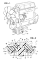
- FIG. 1 is a perspective view of an engine including a first embodiment of a fluid reservoir assembly
- FIG. 2 is a fragmentary cross sectional view of the first embodiment of the fluid reservoir assembly
- FIG. 3 is a fragmentary perspective view of an inner surface of the first embodiment of the fluid reservoir assembly
- FIG. 4 is a fragmentary perspective view of an outer surface of the first embodiment of the fluid reservoir assembly
- FIG. 5 is a fragmentary perspective view of the outer surface of the first embodiment of the fluid reservoir assembly without a plug;
- FIG. 6 is a perspective view of the plug of the first embodiment of the fluid reservoir assembly
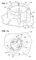
- FIG. 7 is a fragmentary perspective view of a second embodiment of the fluid reservoir assembly
- FIG. 7 a is a fragmentary plan view of the second embodiment of the fluid reservoir assembly
- FIG. 8 is an exploded perspective view of a plug of a third embodiment of the fluid reservoir assembly
- FIG. 9 is a fragmentary plan view of the third embodiment of the fluid reservoir assembly.
- FIG. 10 is an exploded side view of a fourth embodiment of the fluid reservoir assembly.
- a first embodiment of a fluid reservoir assembly is shown generally at 20 in FIG. 1 .
- the reservoir assembly 20 may be incorporated into several different devices.
- One contemplated embodiment of the first embodiment of the fluid reservoir assembly 20 is that of an oil pan for an engine 21 .
- the first embodiment of the fluid reservoir assembly 20 of this disclosure is hereinafter referred to and shown as embodied by an oil pan, it should be understood that the subject invention may be incorporated into other devices, such as a bucket, a pitcher, a power steering fluid pump reservoir, a brake fluid reservoir, etc., and should not be limited to the specific embodiment of an oil pan described herein.
- the first embodiment of the fluid reservoir assembly 20 comprises a pan 22 .
- the pan 22 includes an inner surface 24 and an outer surface 26 .
- the pan 22 defines a cavity for storing a fluid therein, and also defines a drain opening 28 extending through the pan 22 .
- the drain opening 28 allows for removal of the fluid from the cavity as required.
- the fluid includes a motor oil.
- the type of fluid will vary with the different embodiments of the subject invention.
- a plug 30 is disposed within the drain opening 28 .
- the plug 30 is rotatably moveable between a closed position prohibiting fluid flow through the drain opening 28 , and an open position permitting fluid flow through the drain opening 28 .
- the plug 30 includes an aesthetic design to impart the impression of “finger-tight” operation, i.e., the plug 30 is to be manually rotated by hand without the use of a tool, such as a wrench. This may be accomplished be designing the plug 30 to resemble a knob, such as is used for an air conditioning knob within an automobile.
- the plug 30 includes a base 32 disposed adjacent the outer surface 26 of the pan 22 .
- a shaft 34 extends from the base 32 along a central axis C through the drain opening 28 to a distal end 36 .
- the distal end 36 is disposed adjacent the inner surface 24 , within the cavity of the pan 22 .
- the plug 30 further includes at least one wing 38 extending radially outward from the distal end 36 of the shaft 34 , transverse to the central axis C.
- the plug 30 includes a pair of wings 38 as is shown, spaced opposite each other across the shaft 34 , i.e., the wings 38 are spaced 180° apart relative to each other about the shaft 34 .
- At least one ramp 40 is disposed on the inner surface 24 of the pan 22 , within the cavity.
- the reservoir assembly 20 includes a pair of ramps 40 as is shown, spaced opposite each other across the drain opening 28 , i.e., the ramps 40 are spaced apart relative to each other about the drain opening 28 .
- the ramps 40 include a semi-circular shape and are disposed about the outer periphery of the drain opening 28 on the inner surface 24 of the pan 22 adjacent the drain opening 28 . It should be appreciated that the ramps could include some other shape.
- the ramps 40 define a height H which increases in value relative to the inner surface 24 of the pan 22 .
- the height H of the ramps 40 increases along a first direction of rotation, i.e. the ramps 40 define a slope increasing in value along the first direction of rotation.
- the slope may be either constant or variable.
- the height H of the ramps 40 rises from a point on the inner surface 24 measuring 0.0 mm above the inner surface 24 of the pan 22 to a point measuring 3.5 mm above the inner surface 24 of the pan 22 , over a 120° angle of rotation about the drain opening 28 .
- the ramps 40 may be configured to include a different height H and a different angle of rotation about the drain opening 28 .
- the ramps 40 are integrally formed with the pan 22 .
- the ramps 40 may be separate members attached to the pan 22 by suitable methods determined by the type of fluid and conditions of use.
- the wings 38 are in engagement with the ramps 40 .
- the wings 38 are moveable up the ramps 40 , away from the inner surface 24 , in response to rotation of the plug 30 in the first direction of rotation. Movement of the wings 38 up the ramps 40 moves the base 32 into sealing engagement against the outer surface 26 and into the closed position.
- the wings 38 are also moveable down the ramps 40 toward the inner surface 24 of the pan 22 in response to rotation of the plug 30 opposite the first direction of rotation. Movement of the wings 38 down the ramps 40 moves the base 32 out of sealing engagement with the outer surface 26 and into the open position.
- the pan 22 includes a pair of ramps 40 and the plug 30 includes a pair of wings 38 . Therefore, it should be understood that the at least one ramp 40 includes a plurality of ramps 40 and the at least one wing 38 includes a plurality of wings 38 corresponding in number to the plurality of ramps 40 . Accordingly, the reservoir assembly 20 could include three, four, five, or some other number of corresponding ramps 40 and wings 38 , preferably equally spaced about the drain opening 28 and the shaft 34 respectively. As such, it should be understood that the number of ramps 40 and the number of wings 38 may vary, and that the corresponding geometric arrangement of the ramps 40 and wings 38 may also vary accordingly.
- the reservoir assembly 20 further comprises a lock mechanism 42 to secure the plug 30 in the closed position.
- the lock mechanism 42 includes a recess 44 defined by the ramp 40 .
- the recess 44 is spaced from the inner surface 24 for receiving the wings 38 therein, i.e., the recess 44 is at the top of the ramps 40 .
- the wings 38 engage the recess 44 in interlocking engagement to restrain rotation of the plug 30 .
- the recess 44 is disposed 1 mm below the highest elevation of the ramp 40 as measured relative to the inner surface 24 of the pan 22 . Accordingly, when rotating the plug 30 into the closed position, the plug 30 is rotated in the first direction such that the wings 38 travel up the ramps 40 . As the wings 38 travel up the ramps 40 , the base 32 of the plug 30 is drawn closer to the outer surface 26 of the pan 22 . The plug 30 is rotated past the highest portion of the ramp 40 into the recess 44 , where the wings 38 “snap” down into the recess 44 .
- the sensation of the wings 38 snapping into the recess 44 indicates to the user that the plug 30 is in the closed position. Additionally, the wings 38 are prevented from rotating down the ramps 40 , opposite the first direction, thereby loosening the plug 30 , i.e., the wings 38 are locked within the recess 44 to retain the plug 30 within the drain 28 . It should be understood that the lock mechanism 42 may be configured other than as shown and described herein to secure the plug 30 within the drain opening 28 .
- the second and third embodiments of the fluid reservoir assembly 220 , 320 each disclose alternative embodiments for the lock mechanism 242 , 342 .
- the reservoir assembly 20 further comprises a stop 46 .
- the stop 46 prevents rotation of the plug 30 in the first direction past the closed position.
- the stop 46 includes a block 48 disposed on the inner surface 24 of the pan 22 adjacent each of the recesses 44 in each of the ramps 40 .
- the blocks 48 abut the wings 38 when the plug 30 is in the closed position to prevent rotation of the wings 38 past the recess 44 .
- the stop 46 need not include the blocks 48 , and that the stop 46 may include another embodiment as described below or be incorporated into the lock mechanism such as shown in the second embodiment of the fluid reservoir assembly 220 described below. Referring back to FIG.
- the stop 46 may include, independently of or in combination with the blocks 48 , a tab 50 attached to the plug 30 and a wall 52 disposed on the outer surface 26 of the pan 22 to abut the tab 50 when the plug 30 is in the closed position.
- the tab 50 extends radially from the base 32 of the plug 30 transversely to the central axis C.
- the wall 52 is disposed on the outer surface 26 adjacent the drain opening 28 and abuts the tab 50 in the closed position to prevent rotation of the tab 50 past the wall 52 .
- the tabs 50 extend from the plug 30 and are also disposed opposite each other, i.e., 180° apart from each other in corresponding relation relative to the walls 52 .
- the reservoir assembly 20 may include any number of corresponding walls 52 and tabs 50 to prevent over-rotation of the plug 30 .
- the stop 46 may include other devices or configurations suitable to stop over-rotation of the plug 30 other than specifically described herein, or any combination of devices or configurations either disclosed herein or not.
- the pan 22 defines at least one notch 54 adjacent the drain opening 28 to permit the at least one wing 38 to pass therethrough to allow removal and insertion of the plug 30 from and into the drain opening 28 respectively.
- the notches 54 are shaped similarly to, yet slightly larger than the wings 38 to permit the wings 38 to pass therethrough unobstructed.
- the plug 30 may include an indicator 56 for visually indicating that the plug 30 is in the closed position.
- the visual indication of the plug 30 being in the closed position signals the user not to rotate the plug 30 further, thereby damaging the plug 30 or the pan 22 .
- the indicator 56 may include a ridge 58 on the plug 30 that aligns with a marking disposed on the pan 22 when the plug 30 is rotated into the closed position.
- the marking may include one of the walls 52 , as shown, or may include some other indicia on the pan 22 . It should be understood that the indicator 56 may be configured other than shown and described herein to indicate the plug 30 is in the closed position.
- the plug 30 includes a gasket 60 is disposed between the base 32 of the plug 30 and the outer surface 26 of the pan 22 .
- the base 32 defines an annular groove 62 opposing the outer surface 26 with the gasket 60 , comprising a rubber o-ring gasket 60 or the like, disposed within the annular groove 62 .
- gasket 60 comprising a rubber o-ring gasket 60 or the like, disposed within the annular groove 62 .
- gasket 60 comprising a rubber o-ring gasket 60 or the like
- the plug 30 and the pan 22 comprise a polymer.
- the pan 22 and the plug 30 may comprise some other material, such as a metal.
- the pan 22 and the plug 30 may comprise a combination of materials, such as a metal pan 22 and a polymer plug 30 .
- the polymer may or may not include glass reinforcement and should be a higher temperature grade of polymer suitable for use in environments reaching up to 150° C.
- the polymer utilized for the plug 30 and for the pan 22 may include a polyamide (such as Nylon 6 p-grade or Nylon 6/6 p-grade), a polyoxymethylene (such as acetal), or any other polymer suitable for the desired use.
- the polymer material utilized for the plug 30 should be physically compatible with the polymer material utilized for the pan 22 , i.e., the polymer materials for the plug 30 and the pan 22 should have matching thermal expansion characteristics and moisture related dimensional growth characteristics.
- the polymer utilized for the plug 30 and the pan 22 should include an inherent chemical resistance against long term exposure to motor oil under hot environmental conditions, and also include a high impact resistance. It should be understood that the polymer may require different characteristics if utilized with a fluid other than motor oil.
- a specific example of a polymer suitable for the plug 30 and the pan 22 is Ultramid® A3WG7, manufactured by BASF Corporation. It should be understood that other specific types of polymer materials may also be utilized with the subject invention.
- the plug 30 and the pan 22 are manufactured from the polymer material, it is important not to over-rotate or over-tighten the plug 30 to prevent damaging the plug 30 and the pan 22 .
- the plug 30 fails before the pan 22 . Therefore, the plug 30 includes a fracture geometry to ensure the wings 38 fracture before the stop 46 fractures or the pan 22 fractures in response to over-rotation of the plug 30 . Accordingly, in the event of over-rotation of the plug 30 , the plug 30 fails before the pan 22 and only the plug 30 need be replaced.
- the fracture geometry may include a stress line engineered into the plug 30 , separating each of the wings 38 from the shaft 34 , which is engineered to fail upon application of sufficient force to the plug 30 prior to failure of the stop 46 .
- the wings 38 may be engineered to include a shear stress point less than that of the stops 46 by way of having a smaller cross-sectional area or by way of being manufactured from a weaker material than that used to manufacture the stop 46 and the pan 22 . It should be appreciated that the fracture geometry may be accomplished in other manners than specifically described herein so long as the wings 38 fail before the stop 46 or the pan 22 .
- a second embodiment of the fluid reservoir assembly is shown generally at 220 .
- Features of the second embodiment of the fluid reservoir assembly that are also common to the first embodiment of the fluid reservoir assembly are identified with the same reference numeral used for the first embodiment of the fluid reservoir assembly preceded by the integer 2, representing the second embodiment.
- the pan which is common to both the first embodiment of the fluid reservoir assembly 20 and the second embodiment of the fluid reservoir 220 , utilizes the reference numeral 22 in the first embodiment of the fluid reservoir assembly 20 and utilizes the reference numeral 222 in the second embodiment of the fluid reservoir assembly 220 .
- the second embodiment of the fluid reservoir assembly 220 includes an alternative lock mechanism 242 .
- the lock mechanism 242 includes the tabs 250 disposed on the plug 230 engaging at least one seat 266 defined by the pan 222 .
- the tabs 250 are in interlocking engagement when the plug 230 is in the closed position.
- the pan 222 further includes at least one wedge 264 , preferably with a pair of wedges 264 abutting the seats 266 . Accordingly, when rotating the plug 230 from the open position into the closed position, the tabs 250 move along the wedges 264 , and are thereby urged away from each other, with the wedges 264 spreading the tabs 250 slightly until the tabs 250 snap into the seats 266 .
- the second embodiment of the fluid reservoir assembly 220 further includes the walls 252 abutting the tabs 250 and cooperating together to define the stop 246 .
- the block 248 (not shown in FIGS. 7 and 7 a ) may be incorporated into the plug 230 is so desired, or may alternatively be omitted as shown.
- a third embodiment of the fluid reservoir assembly is shown generally at 320 .
- Features of the third embodiment of the fluid reservoir assembly that are also common to the first embodiment of the fluid reservoir assembly are identified with the same reference numeral used for the first embodiment of the fluid reservoir assembly preceded by the integer 3, representing the third embodiment.
- the pan which is common to both the first embodiment of the fluid reservoir assembly 20 and the third embodiment of the fluid reservoir 320 , utilizes the reference numeral 22 in the first embodiment of the fluid reservoir assembly 20 and utilizes the reference numeral 322 in the third embodiment of the fluid reservoir assembly 320 .
- the third embodiment of the fluid reservoir assembly 320 also includes an alternative lock mechanism 342 .
- the lock mechanism 342 includes a snap ring 370 coupled to the plug 330 for rotation with the plug 330 between the open position and the close position.
- the snap ring 370 includes at least one flange 372 , but preferably a pair of radially opposed flanges 372 .
- the flanges 372 are compressible toward the central axis C.
- the lock mechanism 342 further includes at least on depression 374 defined by the pan 322 , but preferably a pair of depressions 374 .
- the flanges 372 engage the depressions 374 in interlocking engagement when the plug 330 is in the closed position.
- the flanges 372 are compressed toward the central axis C to a point where the flanges 372 no longer engage the depressions 374 , thereby allowing rotation of the plug 330 .
- the snap ring 370 is separate from the plug 330 ; however it should be appreciated that the snap ring 370 and the plug 330 could be integrally formed together.
- a fourth embodiment of the fluid reservoir assembly is shown generally at 420 .
- Features of the fourth embodiment of the fluid reservoir assembly that are also common to the first embodiment of the fluid reservoir assembly are identified with the same reference numeral used for the first embodiment of the fluid reservoir assembly preceded by the integer 4, representing the fourth embodiment.
- the pan which is common to both the first embodiment of the fluid reservoir assembly 20 and the fourth embodiment of the fluid reservoir 420 , utilizes the reference numeral 22 in the first embodiment of the fluid reservoir assembly 20 and utilizes the reference numeral 422 in the fourth embodiment of the fluid reservoir assembly 420 .
- the fourth embodiment of the fluid reservoir assembly 420 incorporates an internal fluid removal mechanism 480 for removing the fluid from with in the pan 422 without fully removing the plug 430 from the drain opening 428 .
- the fluid removal mechanism 480 includes a passageway 481 extending through the shaft 434 of the plug 430 .
- the passageway 481 includes a first portion 482 , preferably concentric with the central axis C.
- the first portion 482 extends partially into the shaft 434 of the plug 430 , from the base 432 toward the distal end 436 of the plug 430 .
- the first portion 482 defines a fluid exit 484 at the base 432 of the plug 430 .
- the passageway 481 further includes a second portion 486 , which is in fluid communication with the first portion 482 and extends transverse to the central axis C to an outer edge of the shaft 434 .
- the second portion 486 defines a fluid entrance 488 , so that the fluid may enter through the fluid entrance 488 and flow through the second portion 486 of the passageway 481 and the first portion 482 of the passageway 481 , exiting the fluid reservoir assembly 420 through the fluid exit 484 .
- the inner surface 424 of the pan 422 defines a fluid port 490 for engaging the fluid entrance 488 in fluid communication when the plug 430 is in a drain position.
- the drain position is located between the open position and the closed position.
- the fluid port 490 is disengaged from the fluid entrance 488 when the plug 430 is in the closed position. Accordingly, by rotating the plug 430 from the closed position into the drain position, the fluid entrance 488 becomes aligned with the fluid port 490 .
- the fluid stored within the cavity of the fluid reservoir assembly 420 is then free to flow through the fluid port 490 , into the passageway 481 of the plug 430 , and exit the fluid reservoir assembly 420 through the fluid exit 484 .
- the fluid removal mechanism may be configured other than described or shown herein.
Landscapes
- Engineering & Computer Science (AREA)
- Mechanical Engineering (AREA)
- General Engineering & Computer Science (AREA)
- Lubrication Details And Ventilation Of Internal Combustion Engines (AREA)
- Closures For Containers (AREA)
- Snaps, Bayonet Connections, Set Pins, And Snap Rings (AREA)
- Pressure Vessels And Lids Thereof (AREA)
Priority Applications (1)
| Application Number | Priority Date | Filing Date | Title |
|---|---|---|---|
| US11/867,888 US8069952B2 (en) | 2006-12-06 | 2007-10-05 | Fluid reservoir assembly |
Applications Claiming Priority (2)
| Application Number | Priority Date | Filing Date | Title |
|---|---|---|---|
| US86880406P | 2006-12-06 | 2006-12-06 | |
| US11/867,888 US8069952B2 (en) | 2006-12-06 | 2007-10-05 | Fluid reservoir assembly |
Publications (2)
| Publication Number | Publication Date |
|---|---|
| US20080135340A1 US20080135340A1 (en) | 2008-06-12 |
| US8069952B2 true US8069952B2 (en) | 2011-12-06 |
Family
ID=39266441
Family Applications (1)
| Application Number | Title | Priority Date | Filing Date |
|---|---|---|---|
| US11/867,888 Active 2028-03-10 US8069952B2 (en) | 2006-12-06 | 2007-10-05 | Fluid reservoir assembly |
Country Status (4)
| Country | Link |
|---|---|
| US (1) | US8069952B2 (ja) |
| JP (1) | JP5175294B2 (ja) |
| DE (1) | DE112007002916T5 (ja) |
| WO (1) | WO2008068301A1 (ja) |
Families Citing this family (17)
| Publication number | Priority date | Publication date | Assignee | Title |
|---|---|---|---|---|
| DE202008009179U1 (de) * | 2008-07-09 | 2010-04-22 | Mann+Hummel Gmbh | Ölwannenanordnung eines Kraftfahrzeuges |
| DE102008038260B9 (de) * | 2008-08-11 | 2011-12-15 | Elringklinger Ag | Ölablass-Verschlusselement für eine Motor-Ölwanne |
| DE102009011941A1 (de) | 2009-03-10 | 2010-09-23 | Polytec Automotive Gmbh & Co. Kg | Verschlussschraube für Öffnungen an Kraftfahrzeug-Motoren sowie Gehäuseeinheit eines Kraftfahrzeug-Motors |
| KR101708524B1 (ko) * | 2009-07-14 | 2017-02-20 | 데이나 오토모티브 시스템즈 그룹 엘엘씨 | 플라스틱 팬과 배출 플러그 조립체 |
| DE102009055158B4 (de) * | 2009-12-22 | 2023-06-07 | Elringklinger Ag | Ölwanne mit einer Ölablassöffnung und einem Verschlusselement |
| FR2955146B1 (fr) * | 2010-01-08 | 2012-06-15 | Mark Iv Systemes Moteurs Sa | Carter d'huile en matiere thermoplastique pour moteur a combustion interne et bouchon de vidange pour un tel carter |
| KR101519172B1 (ko) * | 2010-03-31 | 2015-05-11 | 현대자동차주식회사 | 자동변속기의 밸브바디커버 |
| DE102010026429A1 (de) * | 2010-07-08 | 2012-01-12 | Mahle International Gmbh | Ablasseinrichtung |
| DE102010048711B4 (de) * | 2010-10-19 | 2015-11-12 | Ibs Filtran Kunststoff-/ Metallerzeugnisse Gmbh | Aufnahmebehältnis für ein Fluid, insbesondere Motorölwanne oder Getriebeölwanne für ein KFZ |
| US8875933B2 (en) | 2011-09-21 | 2014-11-04 | GM Global Technology Operations LLC | Drainable container system |
| DE102012008521B4 (de) * | 2012-05-02 | 2014-03-27 | Mann + Hummel Gmbh | Ölwannenanordnung |
| DE102012220695A1 (de) * | 2012-11-13 | 2014-05-15 | Dichtungstechnik G. Bruss Gmbh & Co. Kg | Drehverschlussanordnung zum Verschließen einer Öffnung in einem Gehäuseteil eines Verbrennungsmotors, und Verfahren zum Verschließen bzw. Öffnen einer solchen Öffnung |
| JP6637744B2 (ja) * | 2015-11-25 | 2020-01-29 | ダイキョーニシカワ株式会社 | オイルパンのドレン構造 |
| DE102016202692A1 (de) * | 2016-02-22 | 2017-08-24 | Mahle International Gmbh | Verschlusssystem für einen Behälter |
| JP6960316B2 (ja) * | 2017-11-30 | 2021-11-05 | 株式会社マーレ フィルターシステムズ | オイルパンのドレンプラグ構造 |
| KR20190073994A (ko) | 2017-12-19 | 2019-06-27 | 현대자동차주식회사 | 오일팬용 드레인플러그 |
| CN112888839B (zh) | 2018-10-24 | 2023-02-17 | 沃尔沃卡车集团 | 用于流体贮存器的流体排放塞 |
Citations (30)
| Publication number | Priority date | Publication date | Assignee | Title |
|---|---|---|---|---|
| US2241793A (en) * | 1934-08-02 | 1941-05-13 | American Flange & Mfg | Bung or discharge hole formation in a sheet metal container wall |
| US3869391A (en) | 1974-04-01 | 1975-03-04 | Gen Motors Corp | Magnetic drain plug assembly |
| US3910550A (en) * | 1974-05-13 | 1975-10-07 | Illinois Tool Works | Drain plug assembly |
| USRE28844E (en) * | 1973-04-04 | 1976-06-08 | Ford Motor Company | Valve assembly |
| US4025048A (en) | 1975-12-10 | 1977-05-24 | Tibbitts Harry E | Crankcase drain assembly |
| US4449692A (en) * | 1982-11-15 | 1984-05-22 | Ford Motor Company | Drain construction for a radiator |
| US4503934A (en) | 1983-04-11 | 1985-03-12 | Stephanus Tony L | Drain plug with disengagement sealing means |
| US4717119A (en) * | 1985-10-09 | 1988-01-05 | Valeo | Device for bleeding or for draining a heat exchanger, such as a radiator for a motor vehicle |
| US4938314A (en) | 1988-11-11 | 1990-07-03 | Dr. Ing. H.C.F. Porsche Ag | Plastic oil pan |
| US4951783A (en) | 1988-09-15 | 1990-08-28 | Dr. Ing. H.C.F. Porsche Aktiengesellschaft | Arrangement and process for securing a threaded insert to an oil pan |
| US4960153A (en) * | 1989-11-03 | 1990-10-02 | G. T. Products, Inc. | Fuel tank vapor vent valve |
| US5086522A (en) | 1990-06-21 | 1992-02-11 | Stofko Sr George D | Drain plug apparatus |
| US5107808A (en) | 1991-04-15 | 1992-04-28 | Caterpillar Inc. | Reservoir assembly having a drain therein |
| US5176215A (en) | 1991-09-30 | 1993-01-05 | Chicago Rawhide Manufacturing Co. | Composite drain plug |
| US5184698A (en) | 1991-06-21 | 1993-02-09 | Sdi Operating Partners, L.P. | Expandable plug |
| US5197567A (en) | 1991-05-10 | 1993-03-30 | R & B, Inc. | Replacement drain hole closure |
| US5246202A (en) * | 1992-06-19 | 1993-09-21 | General Motors Corporation | Draincock assembly |
| US5299777A (en) | 1993-03-19 | 1994-04-05 | Milstead Brown W | Valved drain plug apparatus |
| US5411115A (en) | 1994-03-07 | 1995-05-02 | Shropshire; Alan | Oil drain plug |
| US5547042A (en) | 1995-01-23 | 1996-08-20 | Platt; Richard B. | Crank case drain plug structure and method |
| US6237639B1 (en) * | 1998-03-18 | 2001-05-29 | Zodiac International | Dump-valve device for a craft and pneumatic craft fitted with same |
| US20030094588A1 (en) | 2001-11-19 | 2003-05-22 | Ching-Da Chen | Oil drain valve |
| US6655499B2 (en) | 2001-11-16 | 2003-12-02 | William D. Metheney, Jr. | Washer and tamper-evident cap for oil plug |
| US20040112855A1 (en) * | 2001-06-07 | 2004-06-17 | West Pharmaceutical Services Deutschland Gmbh & Co. Kg | Closure for a medicament bottle and method for the production thereof |
| JP2005188675A (ja) * | 2003-12-26 | 2005-07-14 | Gp Daikyo Corp | キャップの取付構造 |
| US6942255B2 (en) * | 2002-04-23 | 2005-09-13 | Q3Jmc, Inc. | Twist fitting for air tank connections |
| US20050236229A1 (en) | 2004-04-21 | 2005-10-27 | Hector Olivas | Holding tank drain plug |
| US20060037427A1 (en) * | 2004-08-18 | 2006-02-23 | Ford Global Technologies, Llc | Externally serviceable transmission sump fill pipe and drain port assembly |
| US20060054402A1 (en) | 2004-08-05 | 2006-03-16 | Dorian George P | Two part oil or fluid drain plug with magnet |
| US20060054401A1 (en) | 2004-07-23 | 2006-03-16 | Wilkins John A | Plug for main oil gallery |
Family Cites Families (10)
| Publication number | Priority date | Publication date | Assignee | Title |
|---|---|---|---|---|
| DE2917150C2 (de) * | 1979-04-27 | 1981-06-11 | Blau Kg Fabrik Fuer Kraftfahrzeugteile, 4018 Langenfeld | Verschlußdeckel |
| AU2194883A (en) * | 1982-12-03 | 1984-06-07 | W.A. Deutsher Pty Ltd | Oil filler cap |
| US4497419A (en) * | 1984-02-02 | 1985-02-05 | Stant Inc. | One-piece cap |
| JPS60143966U (ja) * | 1984-03-05 | 1985-09-24 | 株式会社ニフコ | 孔の閉塞装置 |
| US4745894A (en) * | 1987-09-25 | 1988-05-24 | Aeroquip Corporation | Oil drain valve |
| US5637104A (en) * | 1995-06-15 | 1997-06-10 | Abbott Laboratories | Locking cap for the pour spout of a suction container |
| FR2772828B1 (fr) * | 1997-12-22 | 2000-02-25 | Renault | Dispositif d'obturation d'un orifice de remplissage d'huile |
| US6902038B2 (en) * | 1998-04-06 | 2005-06-07 | Tamotsu Takahara | Oil drain plug of engine |
| JP2000264079A (ja) * | 1999-03-17 | 2000-09-26 | Nissan Motor Co Ltd | フィラーキャップの構造 |
| JP2006224774A (ja) * | 2005-02-16 | 2006-08-31 | Fuji Heavy Ind Ltd | 燃料タンクキャップの締付け報知構造 |
-
2007
- 2007-10-05 US US11/867,888 patent/US8069952B2/en active Active
- 2007-12-06 JP JP2009539753A patent/JP5175294B2/ja active Active
- 2007-12-06 WO PCT/EP2007/063394 patent/WO2008068301A1/en active Application Filing
- 2007-12-06 DE DE112007002916T patent/DE112007002916T5/de not_active Withdrawn
Patent Citations (30)
| Publication number | Priority date | Publication date | Assignee | Title |
|---|---|---|---|---|
| US2241793A (en) * | 1934-08-02 | 1941-05-13 | American Flange & Mfg | Bung or discharge hole formation in a sheet metal container wall |
| USRE28844E (en) * | 1973-04-04 | 1976-06-08 | Ford Motor Company | Valve assembly |
| US3869391A (en) | 1974-04-01 | 1975-03-04 | Gen Motors Corp | Magnetic drain plug assembly |
| US3910550A (en) * | 1974-05-13 | 1975-10-07 | Illinois Tool Works | Drain plug assembly |
| US4025048A (en) | 1975-12-10 | 1977-05-24 | Tibbitts Harry E | Crankcase drain assembly |
| US4449692A (en) * | 1982-11-15 | 1984-05-22 | Ford Motor Company | Drain construction for a radiator |
| US4503934A (en) | 1983-04-11 | 1985-03-12 | Stephanus Tony L | Drain plug with disengagement sealing means |
| US4717119A (en) * | 1985-10-09 | 1988-01-05 | Valeo | Device for bleeding or for draining a heat exchanger, such as a radiator for a motor vehicle |
| US4951783A (en) | 1988-09-15 | 1990-08-28 | Dr. Ing. H.C.F. Porsche Aktiengesellschaft | Arrangement and process for securing a threaded insert to an oil pan |
| US4938314A (en) | 1988-11-11 | 1990-07-03 | Dr. Ing. H.C.F. Porsche Ag | Plastic oil pan |
| US4960153A (en) * | 1989-11-03 | 1990-10-02 | G. T. Products, Inc. | Fuel tank vapor vent valve |
| US5086522A (en) | 1990-06-21 | 1992-02-11 | Stofko Sr George D | Drain plug apparatus |
| US5107808A (en) | 1991-04-15 | 1992-04-28 | Caterpillar Inc. | Reservoir assembly having a drain therein |
| US5197567A (en) | 1991-05-10 | 1993-03-30 | R & B, Inc. | Replacement drain hole closure |
| US5184698A (en) | 1991-06-21 | 1993-02-09 | Sdi Operating Partners, L.P. | Expandable plug |
| US5176215A (en) | 1991-09-30 | 1993-01-05 | Chicago Rawhide Manufacturing Co. | Composite drain plug |
| US5246202A (en) * | 1992-06-19 | 1993-09-21 | General Motors Corporation | Draincock assembly |
| US5299777A (en) | 1993-03-19 | 1994-04-05 | Milstead Brown W | Valved drain plug apparatus |
| US5411115A (en) | 1994-03-07 | 1995-05-02 | Shropshire; Alan | Oil drain plug |
| US5547042A (en) | 1995-01-23 | 1996-08-20 | Platt; Richard B. | Crank case drain plug structure and method |
| US6237639B1 (en) * | 1998-03-18 | 2001-05-29 | Zodiac International | Dump-valve device for a craft and pneumatic craft fitted with same |
| US20040112855A1 (en) * | 2001-06-07 | 2004-06-17 | West Pharmaceutical Services Deutschland Gmbh & Co. Kg | Closure for a medicament bottle and method for the production thereof |
| US6655499B2 (en) | 2001-11-16 | 2003-12-02 | William D. Metheney, Jr. | Washer and tamper-evident cap for oil plug |
| US20030094588A1 (en) | 2001-11-19 | 2003-05-22 | Ching-Da Chen | Oil drain valve |
| US6942255B2 (en) * | 2002-04-23 | 2005-09-13 | Q3Jmc, Inc. | Twist fitting for air tank connections |
| JP2005188675A (ja) * | 2003-12-26 | 2005-07-14 | Gp Daikyo Corp | キャップの取付構造 |
| US20050236229A1 (en) | 2004-04-21 | 2005-10-27 | Hector Olivas | Holding tank drain plug |
| US20060054401A1 (en) | 2004-07-23 | 2006-03-16 | Wilkins John A | Plug for main oil gallery |
| US20060054402A1 (en) | 2004-08-05 | 2006-03-16 | Dorian George P | Two part oil or fluid drain plug with magnet |
| US20060037427A1 (en) * | 2004-08-18 | 2006-02-23 | Ford Global Technologies, Llc | Externally serviceable transmission sump fill pipe and drain port assembly |
Also Published As
| Publication number | Publication date |
|---|---|
| JP5175294B2 (ja) | 2013-04-03 |
| WO2008068301A1 (en) | 2008-06-12 |
| DE112007002916T5 (de) | 2009-10-08 |
| JP2010511844A (ja) | 2010-04-15 |
| US20080135340A1 (en) | 2008-06-12 |
Similar Documents
| Publication | Publication Date | Title |
|---|---|---|
| US8069952B2 (en) | Fluid reservoir assembly | |
| US7306010B2 (en) | Ball valve with snap-in stem | |
| CA2124524C (en) | Attachment for thermal probe | |
| US4126023A (en) | Tamperproof locking and latching mechanism for rotatable controls | |
| US4679618A (en) | Draincock and drain hole for a liquid vessel | |
| US5076541A (en) | Tamperproof rotary valve | |
| US4971289A (en) | Valve assembly and locking means therefor | |
| US20060225388A1 (en) | Breather system and method of using the same | |
| US20090057058A1 (en) | Drain plug and method of use | |
| US20060196567A1 (en) | Ball valve with interlocking stem | |
| DE602004002885T2 (de) | Adaptersystem für den Brennstoffbehälter für verbrennungskraftbetriebene Werkzeuge | |
| EP2444604B1 (de) | Aufnahmebehältnis für ein Fluid, insbesondere Motorölwanne oder Getriebeölwanne für ein KFZ | |
| DE102020204099A1 (de) | Volumenausgleichselement für einen Filtereinsatz eines Flüssigkeitsfilters und Filtereinsatz mit einem derartigen Volumenausgleichselement | |
| US6279600B1 (en) | Method for securing a valve cap | |
| DE102014114366A1 (de) | Reifenüberwachungssystem für ein Fahrzeug | |
| US20240101095A1 (en) | Gas-liquid separating gas exchange device | |
| DE102020204098A1 (de) | Filtereinsatz und Flüssigkeitsfilter mit einem derartigen Filtereinsatz | |
| EP1491801A1 (en) | Valve plug and valve provided therewith | |
| US4926900A (en) | Valve assembly and locking means therefor | |
| EP0780535B1 (en) | Adjustable abutment | |
| DE2462265A1 (de) | Auf waermeeinwirkung ansprechendes ventil | |
| US6126142A (en) | Fluid drain device | |
| DE102006021170B4 (de) | Sicherheitsventil | |
| US6752173B2 (en) | Plug means | |
| EP1321636B1 (de) | Schraubverschluss für Flüssigkeitsbehälter, insbesondere einer Ölwanne für Kraftfahrzeuge |
Legal Events
| Date | Code | Title | Description |
|---|---|---|---|
| AS | Assignment |
Owner name: BASF AKTIENGESELLSCHAFT, GERMANY Free format text: ASSIGNMENT OF ASSIGNORS INTEREST;ASSIGNORS:SCHLICKER, SCOTT C.;BALLOU, RAYMOND J.;LEE, CHUL S.;REEL/FRAME:020065/0441;SIGNING DATES FROM 20071029 TO 20071101 Owner name: BASF AKTIENGESELLSCHAFT, GERMANY Free format text: ASSIGNMENT OF ASSIGNORS INTEREST;ASSIGNORS:SCHLICKER, SCOTT C.;BALLOU, RAYMOND J.;LEE, CHUL S.;SIGNING DATES FROM 20071029 TO 20071101;REEL/FRAME:020065/0441 |
|
| STCF | Information on status: patent grant |
Free format text: PATENTED CASE |
|
| FPAY | Fee payment |
Year of fee payment: 4 |
|
| MAFP | Maintenance fee payment |
Free format text: PAYMENT OF MAINTENANCE FEE, 8TH YEAR, LARGE ENTITY (ORIGINAL EVENT CODE: M1552); ENTITY STATUS OF PATENT OWNER: LARGE ENTITY Year of fee payment: 8 |
|
| MAFP | Maintenance fee payment |
Free format text: PAYMENT OF MAINTENANCE FEE, 12TH YEAR, LARGE ENTITY (ORIGINAL EVENT CODE: M1553); ENTITY STATUS OF PATENT OWNER: LARGE ENTITY Year of fee payment: 12 |